Article

LPWAN Networks for Energy Meters Reading and Monitoring Power Supply Network in Intelligent Buildings

1
Institute of Computing Science, Poznan University of Technology, Piotrowo 2, 60-965 Poznan, Poland
2
Poznan Supercomputing and Networking Center, Institute of Bioorganic Chemistry of the Polish Academy of Sciences, Jana Pawła II 10, 61-139 Poznan, Poland
*
Author to whom correspondence should be addressed.
Energies 2021, 14(23), 7924; https://doi.org/10.3390/en14237924
Submission received: 4 November 2021 / Revised: 22 November 2021 / Accepted: 23 November 2021 / Published: 26 November 2021
(This article belongs to the Section G: Energy and Buildings)

Abstract

:
In this paper the idea of functioning of Building Management Systems and Object Management Systems in intelligent buildings is presented. New functionalities of intelligent buildings resulting from the introduction of microgeneration are described. Low-Power Wide-Area Networks (LPWAN) are characterized and compared. The selected Long-Range (LoRaWAN) technology is tested for its use for communication with energy meters and monitoring the power supply network in intelligent buildings. In the paper a new system for reading and monitoring the network is proposed, consisting of hardware, communication, and application layers. A key element of the system is a specially developed converter, which has been designed and tested in a real urban environment. Using our solution in practice could allow to change the architecture of a measurement data acquisition system to much more flexible and efficient.

1. Introduction

Continuous technical progress and the development of new technologies contribute to the constant improvement of living comfort in buildings, where people spend more and more time. Intelligent buildings provide users with comfortable working conditions and their owners with a guarantee to minimize the operating costs of the technical infrastructure. The development of information technology, widespread access to increasingly advanced electronic circuits and progress in the development of advanced automation solutions have caused a revolution in the control and management of technical installations in buildings. For the proper functioning of building installations, to ensure the safety of people and to guarantee appropriate economic effects, it is necessary to obtain a variety of data from devices operating in intelligent buildings, as well as data on the current values of parameters characterizing indoor microclimatic comfort. Standard measurement sensors and complex smart measurement devices are used to acquire this data [1,2]. The functioning of smart measurement devices guarantees real-time access to information on energy consumption and its costs. This information allows the construction of a customer profile and control of power consumption in a manner that maximizes the use of changing peak and off-peak energy prices. This article concerns Low-Power Wide-Area Networks (LPWAN), as a type of wireless networks designed to allow long-range communications at a low bit rate [3]. One of the most popular LPWAN standards—the LoRaWAN (Long-Range Wide-Area Network) [4] technology will be tested for its potential to be used to communicate with electricity meters.
The LoRaWAN technology has been widely analyzed, tested, and discussed in many papers up to now. For a survey concerning applications of LoRaWAN for the Internet of Things (IoT) see, e.g., [5], whereas a comprehensive study of its performance under various parameter setting can be found in [6]. LoRaWAN adaptive data rate has been analyzed in [7,8]. The problem of resource allocation in LoRaWANs has been studied, among others, in [9,10]. Optimization of power allocation in the networks has been considered in [11], whereas energy allocation and optimization in [12,13]. A multi-hop LoRa network protocol with minimized latency has been proposed in [14]. A great variety of LoRaWANs practical applications in different environments have been shown in the literature, e.g., for drone control [15], electric vehicles communication [16], or thermal energy harvesting [17,18].
In this paper we discuss an application of the LoRaWAN network for remote electricity meter reading and power line monitoring in the intelligent building. The goal of this paper is to propose a reading and monitoring system, which consists of three layers: hardware, communication, and application. In the hardwere layer, the component of the system are electricity meters. In the communication layer, a specially developed DLMS/LoRaWAN protocol converter is proposed. In the application layer, an application responsible for measuring data acquisition should be used, which may be one of the well-known cloud platforms. The developed DLMS/LoRaWAN converter was tested for feasibility, correctness and stability of communication between the meter and the LoRa gateway in an urban environment. Basing on the test results we believe that our system can be used to read measurement data from electricity meters in a distribution network and meters installed at customers in a given area. The proposed solution is new in comparison to currently used systems, where usually a central application at the power company’s headquarters initialize a connection to the meter and reads the measurement data. The paper is organized as follows. In Section 2 intelligent buildings are described. The LPWAN networks and their place in the Internet of Things are discussed in Section 3. In Section 4 our proposed system for using LoRaWAN technology in intelligent buildings is presented in detail. In Section 5 we show some experimental results of testing our system in a real urban environment, and we discuss the novelty and advantages of our solution. Section 6 contains concluding remarks and directions for future research.

2. Intelligent Buildings

In defining an intelligent building, it is common to think of a building equipped with building automation that is used to control the functions and technical installations of the building, in particular the most energy-intensive HVAC (Heating, Ventilation, Air Conditioning) system. An extension of the definition of the intelligent building is the information about the functioning of the Building Management System (BMS) in it, in which all technical building installations and control panels are integrated and building management functions are performed [1,19]. If the automation system for processes inside the building is added to the aforementioned functionalities of the BMS, it leads to the definition of the Object Management System (OMS), the task of which is to integrate control of the building with control of the processes occurring in it. Until recently, OMS functioned mainly in industrial facilities, where the processes conducted were characterized by high energy intensity and the linking of building automation with process automation allowed large energy savings to be achieved.
It seems, however, that the functionality of the OMS is bound to expand in the near future as a result of the very dynamic development of new technologies related to energy generation in micro-installations and ways of managing the electrical grid supplying the intelligent building. The evolution of the OMS will probably occur faster in relation to the management of complexes of office buildings, large shopping centers, separated housing estates with complexes of residential buildings.
The ability to produce electricity at the place of use is beginning to have a major impact on the development of the distribution network, the ways in which the network is managed and the need for new automation solutions. Intelligent building functionality will need to be extended to include:
  • electricity generation system equipment, such as a photovoltaic installation installed on the roof or façade of a building,
  • energy storage devices such as electricity storage tanks with the possibility of returning it to the end user for consumption, and thermal energy storage devices in which electricity is converted into thermal energy stored in insulated water tanks for use as domestic hot water or heating water,
  • electric car charging stations.
New building functionalities will necessitate changes in the design principles of electrical installations in new buildings, upgrading of already existing power supply systems and changes in the algorithms for controlling the building’s electricity demand taking into account energy produced on site. It will also be necessary, in view of the local potential in the form of energy storage facilities, to develop a strategy for their optimal use, based not only on demand forecasts but also on forecasts of energy production from own generation sources. A new phenomenon may be an excess of power over current demand and associated reverse energy flows towards the electricity grid.
The aforementioned OMS systems will be required to consider changes in the resource structure of the internal electricity network and, at the same time, expand the range of control criteria used, including control with predictive algorithms [1,19]. In addition to optimizing the energy consumption of a building or building complex, it will be important to reduce energy flows at points of connection to the public electricity grid. The primary objective of the optimization systems will be to utilize own energy resources as much as possible (self-consumption of electricity).
Today, both photovoltaic (PV) systems and small and medium-sized energy storage systems are available on the market. The installation of electric car charging stations, especially in shopping centers or at petrol stations, is becoming increasingly common. In order to utilize the full potential of new technologies in intelligent buildings, it is necessary to define the principles of cooperation between the electricity consumer and the distribution grid operator, both in terms of technical arrangements and legal formalities governing the obligations of both parties. One can assume that the new legal regulations introduced by the “Energy Law” could greatly simplify this process by defining the rules for introducing new technological solutions into the network of end customers.
Intelligent buildings and their environments have been analyzed in many scientific papers from various points of view, e.g., integration based on mobile devices [20], building management [21], control system [22], heating energy management [23], energy and stock exchange [24], and many others.

3. Long-Range Radio Networks LPWAN and the Internet of Things

It is essential for the control system in intelligent buildings to ensure communication between sensors and actuators and the BMS. The communication is most often realized using a serial bus connection (e.g., twisted pair bus), 230 VAC power supply network (PLC—Power Line Communication technology) and RF connections (short-range radio technology). In wireless communication, the following standards can be distinguished: Zigbee, Z-Wave, Bluetooth, Wireless M-bus and WiFi [25]. All of these technologies can be applied to read water, heat, gas and electricity meters, as long as the distances between devices in the network are within the range of the technology. The distance is typically between a few meters and a few tens of meters.
New possibilities in communication between actuators and measurement sensors and control and management systems have emerged with the development of technologies dedicated to the IoT. These are wireless communication solutions such as Sigfox, LoRaWAN, LTE Cat M1, NB-IoT, RF Mesh, referred to as LPWANs. The common feature of these solutions is to achieve longer ranges and to reduce the power of the terminal equipment at the expense of reduced throughput [4]. It should be noted that in addition to the radio technologies mentioned above, GSM/GPRS/LTE mobile networks have been used for many years to communicate with various devices. Examples include remote reading systems for electricity meters installed in higher voltage electricity networks (networks above 1 kV). With the introduction of smart metering, i.e., smart meters for utility customers, GSM/GPRS/LTE technologies have also started to be used for remote meter reading in low voltage networks.
The rapid growth of the IoT has resulted in a two-pronged development of GSM/GPRS/LTE devices and a split between devices designed for mobile communications and devices dedicated to the IoT also called Cellular IoT (CIoT). Two of the most prevalent standards appeared in the CIoT area: LTE Cat M1 and Narrowband IoT (NB-IoT). With the development of 5G architecture for the next generation of LTE devices and the development of cloud computing platforms, another concept has been introduced: Industrial IoT (IIoT) which refers to devices that support manufacturing processes and industrial technologies.
Table 1 shows the characteristics of LPWAN communication networks used in the IoT field. For performance comparison, Cellular IoT technologies introduced by mobile network operators, operating in licensed frequency bands, and technologies that use unlicensed ISM bands are contrasted. Three of the presented operate in the 868 MHz band: Sigfox, LoRaWAN, Wi-SUN (Wireless Smart Utility Network), the last of which is particularly predisposed to reading electricity, water and gas meters [26]. The Wi-SUN network is based on the IEEE 802.15.4g standard describing a network of end devices operating in a Mesh configuration where, unlike Sigfox and LoRaWAN, the end devices do not need to be connected directly to the base station when there is no radio coverage, but can be connected through another end device or a Wi-SUN router. Such architecture makes the Mesh network dynamically configurable depending on the placement of devices in the area and the quality of the radio signal for connections between devices and between devices and the base station.
The technologies listed in Table 1 differ not only in their technical parameters, but also in the conditions related to implementation, equipment costs, operating costs, the required degree of security of the communication channel as well as the reliability and size of the system.
A comparison of communication technologies can be made based on the criteria presented below, relevant to the requirements for the IoT [27]:
  • Quality of service—understood as reliability. In terms of mobile operator services, it is large but comes with a higher cost of service. In addition, the service is standard, so it is available throughout the country, for example. On the other hand, if reliability and transmission speed parameters are not a priority, it is possible to use a LoRaWAN network at a lower cost and achieve a comparable communication range.
  • Battery life and sleep mode—parameters that affect how long the device works without servicing. For CIoT devices, the battery power consumption is higher but the response time of the end devices is shorter and the transmission speed is higher compared to LoRaWAN.
  • Network coverage and range—in terms of devices and networks, the coverage for CIoT will be the same as for LTE (same base stations), however, it is required that the LTE network operator activates device support in the area. Private networks based on ISM bandwidth may have better coverage and range in rural areas, while in urban areas the performance is comparable. Both parameters depend on the output power, where for LTE it is 20 to 23 dBm or 100 to 200 mW, and for the 868 MHz band it is 14 dBm, which is 25 mW. Thus, despite being several times less powerful, these networks match the range and coverage of CIoT networks. This is their strong advantage when building a private independent long-range network.
  • Location—depending on the intended use, the network can be based on existing mobile base stations, therefore the cost of launching a new service on existing infrastructure is not large. On the other hand, this can be a limitation compared to for example LoRaWAN technology, where the deployment of gateways in the field can be adapted to specific project requirements.
  • Network cost—includes the cost of terminal equipment, base stations, gateways, commercial cloud application fees, LTE network subscriptions. Preparing completely private networks, for example LoRaWAN, also requires costs to build own layer of network servers and application servers.
Among the technologies presented in Table 1, considering both technical parameters and device availability as well as support from existing and proven cloud platforms, LoRaWAN technology was selected for testing in terms of electricity meter reading capabilities.
A significant advantage of this network over other technologies is the lower cost of the end devices and the cost of implementing the network itself. Whereas the achievable communication ranges are comparable to commercial LTE networks. In addition, the gateway network can be densified or reconfigured at will, depending on the requirements of the particular communication network design.

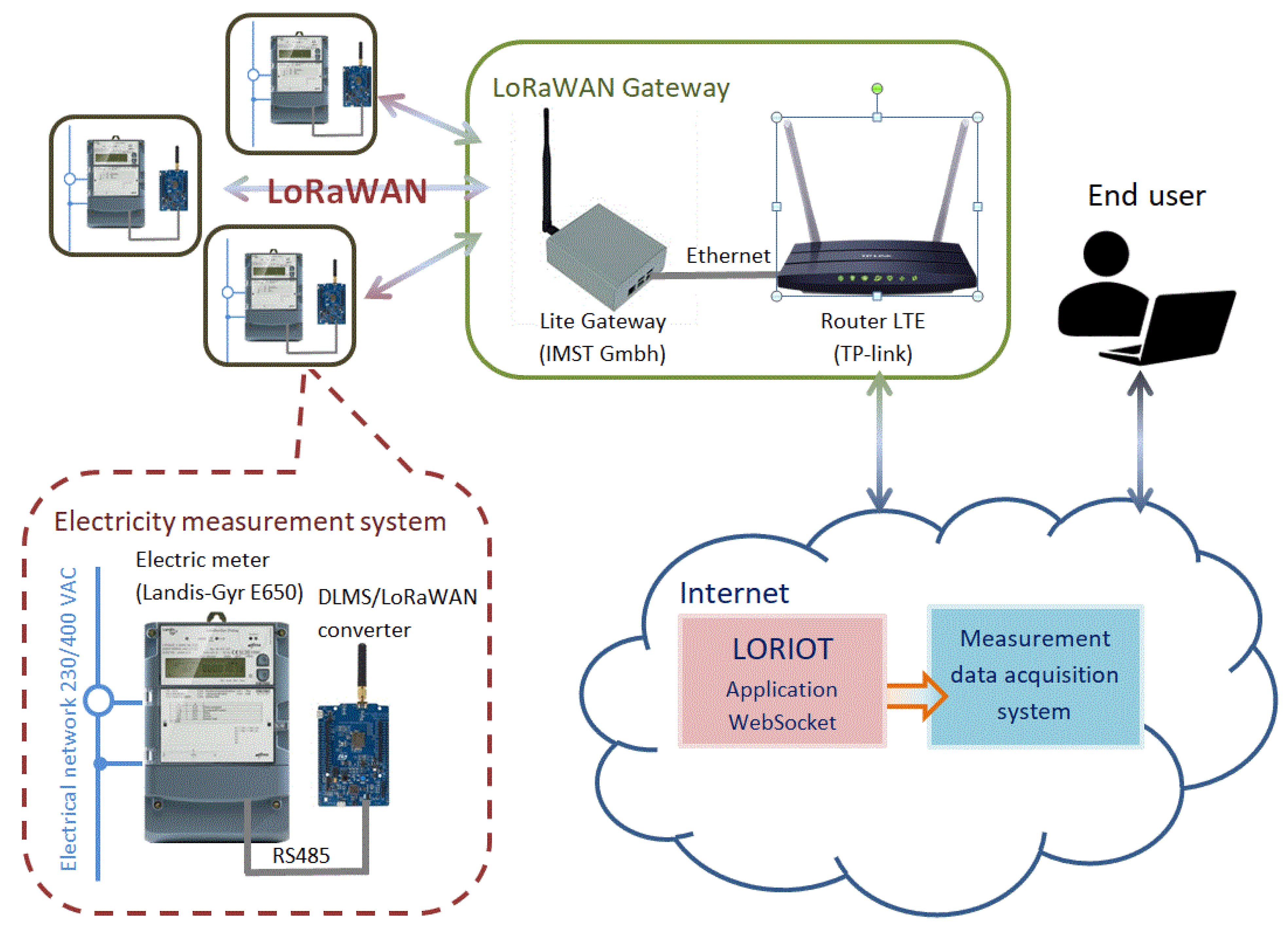
4. The Proposed System

In this section we describe the proposed system using LoRaWAN to communicate with electricity meters and monitor the power supply network in buildings. With the significant expansion of the power structure and the linkages between energy generation, storage and consumption, it is necessary to implement an internal metering and management system for energy flows in the grid. The system should consist of electricity meters, communication layer devices and an application responsible for measuring data acquisition. The building energy flow metering system should function at the OMS level.

4.1. Hardware Layer—Electricity Meters

The first component of the system is the meters, most often already in place, installed at the boundary with the public grid and used for billing with the energy supplier, and the meters in the internal grid designed for billing with consumers. Followed by meters at all key points in the network.
It is required to use 3-phase, bidirectional meters for active and reactive energy measurement (such requirements are fulfilled by, e.g., E650 ZMD410CT44.0459 meter from Landis + Gyr), equipped with a number of additional elements and functions, such as [28]:
  • a module for energy and power tariffs and an internal timer that controls the module’s operation,
  • recording of load profiles for all types of energy—consecutive values of energy registers stored every 15 min,
  • recording of total energy and for each phase,
  • measuring of total active and reactive power and for each phase separately,
  • measurements of network values such as voltages, currents, power factor, coefficient of higher harmonic content in voltages and currents, network frequency,
  • recording of events affecting reliability of measurements, anti-theft functions,
  • additional two-state outputs allowing to configure alarm signals,
  • additional power supply unit that sustains operation of the meter in the event of shutdown of a particular receiver or measuring point,
  • communication interfaces including both electrical connector standards (RS232, RS485) and communication protocol standards, the most commonly used of which is the protocol described by the IEC 62056 series of standards package, called DLMS (Device Language Message Specification) protocol.
In the expanded metering system it is also possible to apply the so-called smart meters, which will be installed mainly at municipal customers, having, in addition to the previously mentioned standard functions, also additional functions, such as:
  • remotely controlled disconnector that allows to switch off individual consumers when their active power exceeds a certain level
  • additional interface for communication with the Home Area Network (HAN)
  • the possibility of sending from the metering system to the meter display text information intended for a given customer
  • providing information on energy consumption in real time, which allows the recipient to make decisions about choosing the optimal tariff for the time of lower or higher energy consumption.
The abovementioned additional functions of smart meters are their definitive advantages. It is worth noticing that providing information on the current energy consumption may change the habits of consumers (e.g., launching receivers at a cheaper tariff) and increase the self-consumption of energy produced on site from renewable sources. However, smart meter do also have some disadvantages, as they often make the recipient feel a lack of privacy and constant surveillance. There is also a theoretical possibility of breaking into the IT system managing smart meters, and gaining access to personal data of recipients and their operating profiles as customers of the electricity distribution system.
Among the functions listed above, communication interfaces become particularly important in the context of new information technologies based on cloud platforms for data processing and visualization, the development of web services, and the use of artificial intelligence algorithms for object control. In the event of metering systems, the condition that determines the introduction of new IT solutions is continuous access to metering data in real time, and thus access to the communication interface of the meter. The DLMS protocol mentioned earlier is a proven and used communication standard for electricity metering systems. It is used in direct 1-phase meters (e.g., smart meters) for installation at municipal customers, as well as in 3-phase meters installed at building connections, in shopping centers, office buildings and at industrial customers. The protocol includes two features that are important in terms of communication method:
  • the data exchange between the device and the reading system is based on the client/server model, where the meter acts as a server,
  • the protocol is connection-oriented, where a communication session includes 3 phases: establishing a connection at the application level, exchanging packages and reading data, and terminating the connection session; the entire process must continue uninterrupted [29].
The protocol was originally developed for meter reading over a landline switched network. After that, it was used in GSM networks of subsequent generations: 2G, 3G until the current 4G network—LTE. The protocol structure allows users with appropriate rights to establish a connection and open a communication session, and then remotely access meter data and parameters. Communication most often requires the use of modems or network routers and the use of paid services of mobile operators to ensure the required continuity of connection and low delays (of several hundred milliseconds) of transmitted packages.
The described method of communication results from the data acquisition system architecture concept. The application together with the database is installed in a central location from where (for example, once a day) connections to the meters and reading of the measured data are initiated. The software must contain implemented protocol drivers, ensuring reading of devices from various manufacturers. Although there is one standard—IEC 62056, in practice each manufacturer implements it in the meter in a slightly different way, which leads to the need of implementing several DLMS protocol drivers in the system.

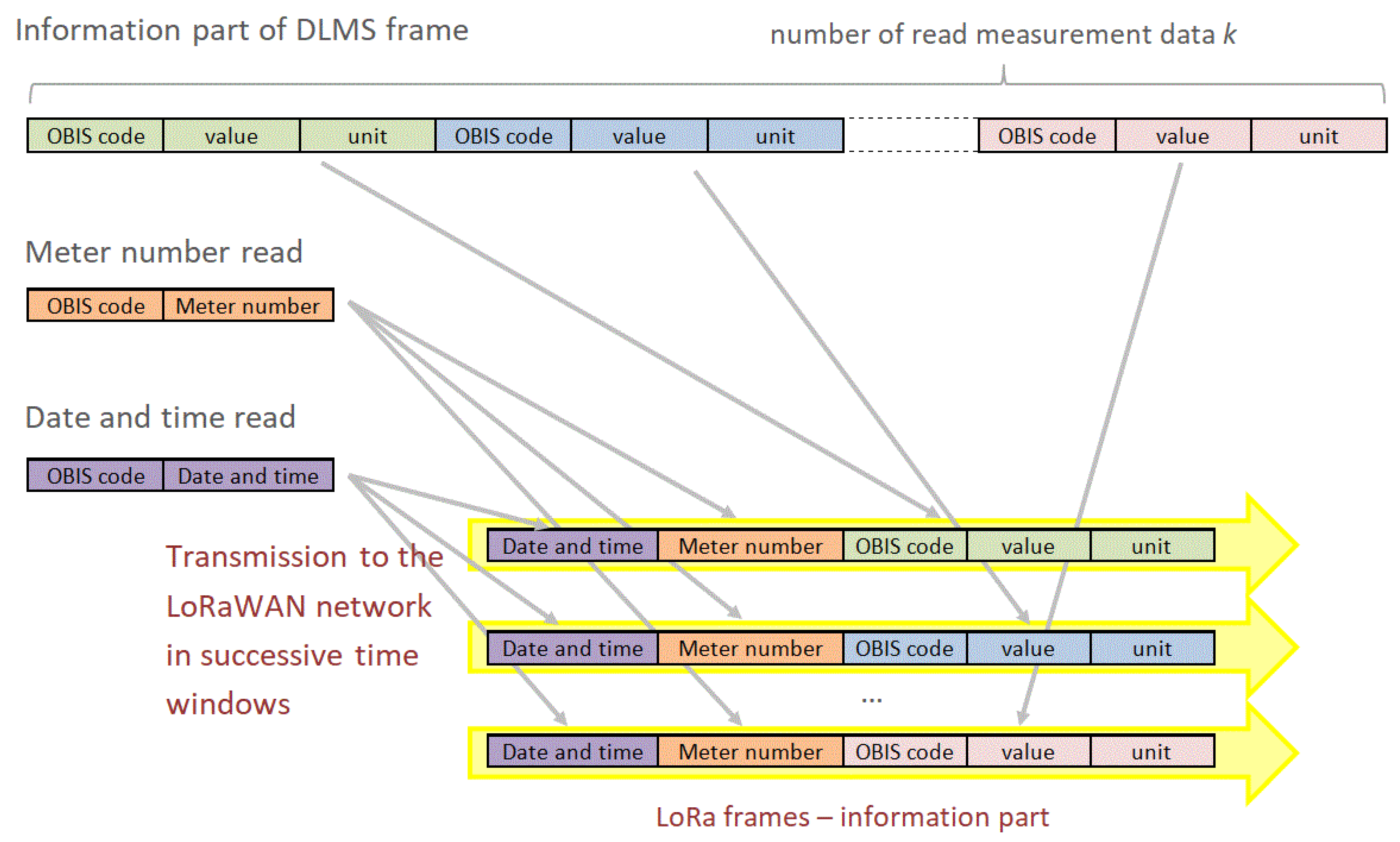
4.2. Communication Layer

The second element of the metering system is the communication layer devices and the network technology used. Until now, the most common solution used was the aforementioned mobile operator’s network or a TCP/IP Ethernet network if it had been previously delivered to all meter locations. Both solutions have their limitations. The limitation of the former is related to the need to pay for telecommunications services. The second one requires an extensive internal TCP/IP network, because its expansion only for the needs of the metering system causes oversizing of communication channels and is uneconomical.
The use of LoRaWAN to communicate with electricity meters required solving two problems, outlined below:
  • Features of the DLMS protocol prevent meters from being incorporated directly into the LoRaWAN without the need for additional intermediary devices. The network does not provide the connection continuity required by the DLMS, as due to ISM bandwidth occupancy limits of up to 1%, intervals between successive data frames are required. In fact, even at the highest predicted speeds, the interval between frames can be as long as 2 s [30].
  • The LoRaWAN protocol for class A end devices primarily assumes unidirectional (uplink) communication, thus sending data from the device to the application server [31]. High channel capacity is not expected for the downlink direction. This feature makes it completely impossible to use the DLMS session connection mode, in which reading relies on the exchange of request-response frames.
In order to solve the presented problems, a DLMS/LoRaWAN protocol converter was developed, which main task is to cyclically read the metering data locally from the electricity meter using the DLMS protocol, process them into a format and size of packages possible to transmit over a LoRaWAN network, and then send them over a radio channel to the gateway of the network. The communication channel structure with the converter is shown in Figure 1. The device is equipped with three communication ports:
  • RS485 interface designed for local communication with the meter, supported by DLMS protocol driver implemented in the converter,
  • USB port used for parameterization of the device and local monitoring of the read measurement data and for supplying the converter; when local monitoring is not necessary, the port is used only for connecting the power supply unit,
  • LoRa radio interface with embedded LoRaWAN network protocol stack provided by ST Microelectronics in the form of internal software libraries for STM32L0—ARM Cortex M0+ microcontrollers.
From the network point of view, the converter becomes a terminal device—an end-node, which on the one hand realizes the data exchange with the meter in client/server mode, and on the other hand is a source of data periodically sent in “push” mode via gateway to the application dealing with measurement data acquisition. The logical structure of a DLMS frame and how its information part is processed into the corresponding set of clique frames of LoRaWAN is shown in Figure 2. In the information parts of both DLMS and LoRa frames the Object Identification System (OBIS) is used which defines the identification codes for commonly used data items in electricity metering equipment. The OBIS codes are described in the international standard IEC 62056-61. The converter enables the parameterization of the meter reading frequency and the list of read quantities. While testing the operation of the converter in the system shown in Figure 1, a reading of 10 different quantities recorded or measured by the meter was obtained every 5 min. The format of the information part of LoRa frames can be prepared in various ways depending on the requirements of the data acquisition application. One popular format, used for example in web applications, is the JSON format that is possible to implement in the converter software. For interesting papers discussing web services see, e.g., [32,33,34].

4.3. Application Layer
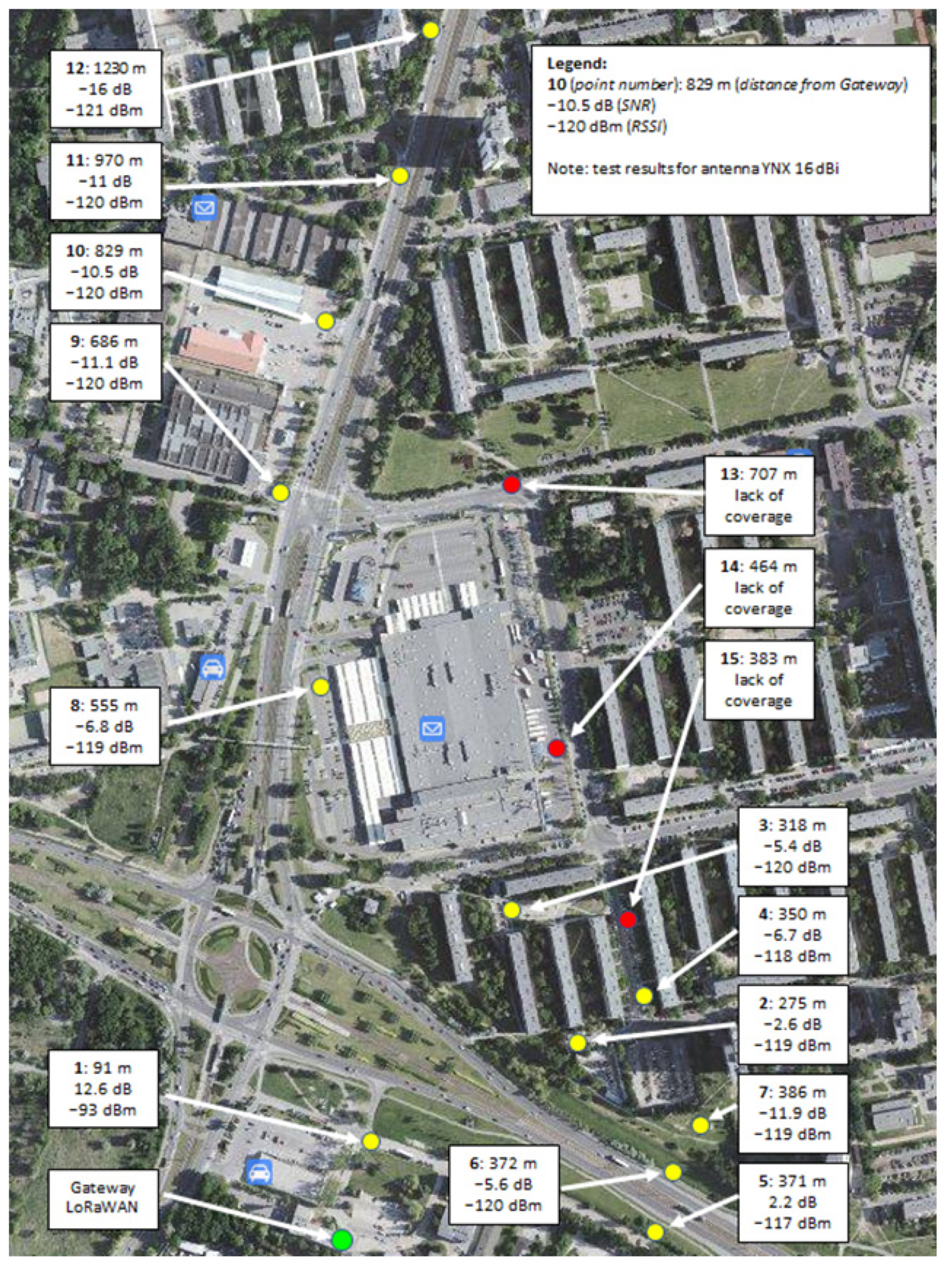
The use of a converter allows to change the architecture of the measurement data acquisition system and to shift the meter reading to a local device. It is not an application that executes the schedule of reading (polling) all meters once a day or once every few hours, but a system operating in a listening mode, collecting on-line data incoming from many devices at the same time. The concept of a system that works in this manner is itself not new. Reading of electricity meters using the LoRaWAN network was implemented in systems used for billing of municipal consumers, where meters with an internal radio modem operating in the LoRa standard, specially designed for such a solution, were used [35]. In regards to the communication protocol, the reading was limited to only one measured value of active energy.
The DLMS/LoRaWAN converter connected to electricity meters installed in electricity grid connections and in the customer’s internal network allows data acquisition from standard devices equipped with a DLMS interface.
Returning to the description of the intelligent building management system provided at the beginning of the paper, it is possible to consider how to place the architecture presented above in the structure of the BMS or OMS. In the event of a large number of devices—converters and an increase in the frequency of readings, a stream of information is obtained, which in the host layer will require pipelined processing.
Another solution for the application layer could be to move the data acquisition to a cloud platform or to use off-the-shelf platforms offering LoRaWAN network management services. Popular platforms of this type are: The Things Network, LORIOT, Actility, Cisco and ResIOT. The services offered on the platforms for commercial applications are chargeable, hence such solutions require appropriate financial calculations in advance. Among the services offered is also the integration of LoRaWAN with the Microsoft Azure development environment, located in the cloud, and the possibility of using the applications for the IoT offered on the platform.

5. Discussion

In this section we would like to conduct a discussion on the originality, novelty, and quality of our proposed system. Let us start the discussion with presenting the results of some testing experiments.
The developed DLMS/LoRaWAN converter was tested in terms of the feasibility, correctness and stability of communication between the meter and the LoRa gateway in real conditions, in dense urban environment. Measurements of communication quality parameters were carried out in several places in the city, with a simulation of the operating conditions of the measurement data acquisition system. The main goal of the experiments was to confirm the possibility of reading data from the meter, and then to determine the throughput of the communication channel as a number of readable quantities in a given period of time.
The tests were carried out in compliance with the requirements of the EU 868 MHz standard for the ISM (Industrial, Scientific, Medical) band in accordance with the ETSI (European Telecommunications Standards Institute) recommendations. Therefore, the maximum power of the radio signal (output power of the communication module) was limited to +14 dBm (up to 25 mW), and the transmission time was limited to 1% of the bandwidth. From a practical point of view, it was important to determine the parameters of the radio signal depending on the distance from the LoRa gateway, as well as on local conditions related to the topography, buildings and obstacles between the gateway and the converter and meter.
Contrary to commercial smart metering solutions, where readings are made every 15 or even every 60 min, during our experiments readings were assumed every 5 min. During the tests, the distance of the meter from the gateway, as well as the values of the SNR (Signal-to-Noise Ratio) and RSSI (Received Signal Strength Indicator) parameters were recorded. Measurements were made in Poznań near Starołęka roundabout, for 15 selected points from the smallest to the largest distance between the meter and the gateway.
The results of the testing experiments are presented on the map presented in Figure 3. For each point the distance, SNR and RSSI are given. Analyzing the obtained results, the following observations can be made:
  • The maximum range of network operation obtained during the tests (1230 m) was shorter than given in the catalog data of the gate manufacturer.
  • The influence of the landform can be clearly seen—high buildings are obstacles for the radio signal (see points 13, 14, and 15).
  • Increasing the height of the gateway antenna mounting significantly improves the quality of communication.
Taking into account the above conclusions, let us now shortly discuss the advantages of our solution.
It can be stated that the developed DLMS/LoRaWAN converter can be used to read measurement data from smart electricity meters at key points in the distribution network and meters installed at customers in a selected area. Currently, the most commonly used architecture of the energy consumption metering data acquisition system is a central application connected to a database, usually installed at the power company’s headquarters, from where the connection to the meter is initiated (e.g., once a day) and the measurement data readout is made. The use of the developed converter allows to change the architecture of the measurement data acquisition system and to shift the meter reading to a local device, and then transfer the measurement to the data acquisition system. Then we obtain a much greater flexibility of the system, e.g., by adjusting the format of the forwarded data to the requirements of the measurement data processing system. The entire system can operate in on-line listening mode, and collect data coming from many meters at the same time.
The very concept of a data collection system functioning in this way is not new, but so far it has not been used in practice in relation to smart electricity meters installed, for example, at industrial customers.

6. Conclusions

Among the available low-energy wireless communication networks, LoRaWAN technology was selected for analysis. The LoRaWAN network was used for remote electricity meter reading and power line monitoring in the intelligent building. The proposed remote reading and monitoring system consists of a hardware layer, which is the energy meters, a communication layer, which is the developed DLMS/LoRaWAN protocol converter, and an application layer, where off-the-shelf cloud platforms can be used. The presented system, based on LoRa network communication, meets the conditions for energy metering systems in the intelligent buildings. In such facilities, access to real-time data is a prerequisite for optimal management of power consumption and, in the case of microgeneration operation, also for appropriate management of access to stored energy. LoRaWAN technology, as one of the representatives of low-energy wireless networks, can be successfully used in the intelligent buildings for monitoring the electrical grid, remote reading of electricity, heat and water meters. The proposed system was tested in a dense urban environment. The results show that the system can be used in real conditions for reading measurement data from electricity meters at vital points in the power network, as well as from meters installed at customers. Its architecture, in comparison to systems most commonly used these days, allows to obtain a much greater flexibility of the system, e.g., by adjusting the transmitted data format to the standards of the measurement data processing system. The system can operate in on-line listening mode, and collect data coming simultaneously from a number of meters.
The limitations of the research at its current stage follows from the fact that we carried out the experiments in one meter—one LoRa gateway configuration. We did not tested the communication range and correctness in the case of transmitting measurement data to the LoRa gateway from a large number of meters (e.g., several hundred). Positive results of the research on the possibility of connecting a large number of converters and meters with the LoRa gateway could give grounds for attempting to commercialize the converter prototype.
In the future research we plan to examine the efficiency of the system with one LoRaWAN gateway under an increasing number of electricity meters, and defining a relation between the number of meters and the number of required gateways. Another direction could be applying artificial intelligence (AI) methods for optimizing the transmission parameters in order to keep stability of operation of a single-gateway system.

Author Contributions

Conceptualization, M.N. and P.D.; methodology, M.N.; validation, P.D.; formal analysis, K.K.; writing—original draft preparation, M.N., R.R. and G.W.; writing—review and editing, M.N., R.R. and G.W.; supervision, K.K.; project administration, K.K. All authors have read and agreed to the published version of the manuscript.

Funding

This research received no external funding.

Data Availability Statement

All data needed for the testing experiments were collected by the authors.

Acknowledgments

This research has been partially supported by the statutory funds of Poznan University of Technology.

Conflicts of Interest

The authors declare no conflict of interest.

Abbreviations

AcronymExplanation
BMSBuilding Management System
OMSObject Management System
LPWANLow-Power Wide-Area Network
LoRaWANLong-Range Wide-Area Network
IoTInternet of Things
CIoTCellular Internet of Things
NB-IoTNarrowband Internet of Things
IIoTIndustrial Internet of Things
HVACHeating, Ventilation, Air Conditioning
PVPhotovoltaic
DLMSDevice Language Message Specification
PLCPower Line Communication
GSMGlobal System for Mobile Communications
GPRSGeneral Packet Radio Service
LTELong Term Evolution
Wi-FiWireless Fidelity
Wi-SUNWireless Smart Utility Network
BPSKBinary Phase Shift-Keying
DBPSKDifferential Binary Phase Shift-Keying
QPSKQuadrature Phase Shift Keying
FSKFrequency-Shift Keying
GFSKGaussian Frequency-Shift Keying
QAMQuadrature Amplitude Modulation
CSSChirp Spread Spectrum
HANHome Area Network
OBISObject Identification System
AIArtificial Intelligence
ISMIndustrial, Scientific, Medical
ETSIEuropean Telecommunications Standards Institute

References

  1. Tang, S.; Shelden, D.R.; Eastman, C.H.M.; Pishdad-Bozorgi, P.; Gao, X. BIM assisted Building Automation System information exchange using BACnet and IFC. Autom. Constr. 2020, 110, 1–14. [Google Scholar] [CrossRef]
  2. Harish, V.S.K.V.; Kumar, A. A review on modeling and simulation of building energy systems. Renew. Sustain. Energy Rev. 2015, 56, 1272–1292. [Google Scholar] [CrossRef]
  3. Peruzzi, G.; Pozzebon, A. A Review of Energy Harvesting Techniques for Low Power Wide Area Networks (LPWANs). Energies 2020, 13, 3433. [Google Scholar] [CrossRef]
  4. LoRa Alliance Website, LoRa Technology. Available online: https://lora-alliance.org/about-lorawan (accessed on 4 November 2021).
  5. Haxhibeqiri, J.; De Poorter, E.; Moerman, I.; Hoebeke, J. A survey of LoRaWAN for IoT: From technology to application. Sensors 2018, 18, 3995. [Google Scholar] [CrossRef] [Green Version]
  6. Magrin, D.; Capuzzo, M.; Zanella, A. A thorough study of LoRaWAN performance under different parameter settings. IEEE Internet Things J. 2019, 7, 116–127. [Google Scholar] [CrossRef] [Green Version]
  7. Finnegan, J.; Farrell, R.; Brown, S. Analysis and Enhancement of the LoRaWAN Adaptive Data Rate Scheme. IEEE Internet Things J. 2020, 7, 7171–7180. [Google Scholar] [CrossRef]
  8. Farhad, A.; Kim, D.H.; Subedi, S.; Pyun, J.Y. Enhanced LoRaWAN Adaptive Data Rate for Mobile Internet of Things Devices. Sensors 2020, 20, 6466. [Google Scholar] [CrossRef]
  9. Farhad, A.; Kim, D.H.; Kim, B.H.; Mohammed, A.F.Y.; Pyun, J.Y. Mobility-Aware Resource Assignment to IoT Applications in Long-Range Wide Area Networks. IEEE Access 2020, 8, 186111–186124. [Google Scholar] [CrossRef]
  10. Farhad, A.; Kim, D.H.; Pyun, J.Y. Resource Allocation to Massive Internet of Things in LoRaWANs. Sensors 2020, 20, 2645. [Google Scholar] [CrossRef] [PubMed]
  11. Al-Gumaei, Y.A.; Aslam, N.; Chen, X.; Raza, M.; Ansari, R.I. Optimising Power Allocation in LoRaWAN IoT Applications. IEEE Internet Things J. 2021. [Google Scholar] [CrossRef]
  12. Gleonec, P.D.; Ardouin, J.; Gautier, M.; Berder, O. Energy Allocation for LoRaWAN Nodes with Multi-Source Energy Harvesting. Sensors 2021, 21, 2874. [Google Scholar] [CrossRef]
  13. Khalifeh, A.; Aldahdouh, K.; Alouneh, S. LoRaWAN Energy Optimization with Security Consideration. Int. Arab. J. Inf. Technol. 2021, 18, 476–483. [Google Scholar] [CrossRef]
  14. Mai, D.L.; Kim, M.K. Multi-Hop LoRa Network Protocol with Minimized Latency. Energies 2020, 13, 1368. [Google Scholar] [CrossRef] [Green Version]
  15. Sharma, V.; You, I.; Pau, G.; Collotta, M.; Lim, J.D.; Kim, J.N. LoRaWAN-Based Energy-Efficient Surveillance by Drones for Intelligent Transportation Systems. Energies 2018, 11, 573. [Google Scholar] [CrossRef] [Green Version]
  16. Rinaldi, S.; Pasetti, M.; Sisinni, E.; Bonafini, F.; Ferrari, P.; Rizzi, M.; Flammini, A. On the Mobile Communication Requirements for the Demand-Side Management of Electric Vehicles. Energies 2018, 11, 1220. [Google Scholar] [CrossRef] [Green Version]
  17. Bäumker, E.; Conrad, L.; Comella, L.M.; Woias, P. A Fully Featured Thermal Energy Harvesting Tracker for Wildlife. Energies 2021, 14, 6363. [Google Scholar] [CrossRef]
  18. Cappelli, I.; Parrino, S.; Pozzebon, A.; Salta, A. Providing Energy Self-Sufficiency to LoRaWAN Nodes by Means of Thermoelectric Generators (TEGs)-Based Energy Harvesting. Energies 2021, 14, 7322. [Google Scholar] [CrossRef]
  19. Bhatt, J.; Verma, H.K. Design and Development of Wired Building Automation Systems. Energy Build. 2015, 103, 396–413. [Google Scholar] [CrossRef]
  20. Dospinescu, O.; Perca, M. Technological integration for increasing the contextual level of information. Analele Ştiinţifice Universităţii Alexandru Ioan Cuza Iaşi. Ştiinţe Economice 2011, 58, 571–581. [Google Scholar]
  21. Jia, C.; Ding, H.; Zhang, C.; Zhang, X. Design of a dynamic key management plan for intelligent building energy management system based on wireless sensor network and blockchain technology. Alex. Eng. J. 2021, 60, 337–346. [Google Scholar] [CrossRef]
  22. He, Y.; Du, Y.; Guo, H.; Yang, J.; Sun, Y.; Wang, Z.; Li, C.; Sun, K.; Zhang, M.; Shi, C.; et al. Design and Research of Intelligent Building Control System. In Proceedings of the IOP Conference Series: Earth and Environmental Science, Kamakura City, Japan, 10–11 October 2021; Volume 632, p. 042023. [Google Scholar]
  23. Prusak, D.; Karpiel, G.; Kułakowski, K. The Architecture of a Real-Time Control System for Heating Energy Management in the Intelligent Building. Energies 2021, 14, 5402. [Google Scholar] [CrossRef]
  24. Dospinescu, O.; Dospinescu, N. A profitability regression model of Romanian stock exchange’s energy companies. In Proceedings of the 17th International Conference on Informatics in Economy Education, Research & Business Technologies, Iasi, Romania, 17–20 May 2018; pp. 169–174. Available online: https://www.researchgate.net/publication/325847421 (accessed on 12 November 2021).
  25. Antonowicz, A.; Derbis, P.; Nowak, M.; Urbaniak, A. Smart Meter in Voltage Control System of Power Network. In Proceedings of the 21th International Carpathian Control Conference (ICCC), High Tatras, Slovakia, 27–29 October 2020; pp. 1–6. [Google Scholar] [CrossRef]
  26. Harada, H.; Mizutani, K.; Fujiwara, J.; Mochizuki, K.; Obata, K.; Okumura, R. IEEE 802.15.4g Based Wi-SUN Communication Systems. IEICE Trans. Commun. 2017, E100-B, 1032–1043. [Google Scholar] [CrossRef] [Green Version]
  27. Sinha, S.R.; Wei, Y.; Hwang, S. A survey on LPWA technology: LoRa and NB-IoT. ICT Express 2017, 3, 14–21. [Google Scholar] [CrossRef]
  28. Electricity Meter IEC/MID, Industrial and Commercial, ZMD300AT/CT E650 Series 3, User Manual. Available online: https://www.landisgyr.eu/webfoo/wp-content/uploads/2012/09/D000030108-E650-ZMD300xT-Series-3-User-Manual-en-k.pdf (accessed on 4 November 2021).
  29. DLMS User Association. Green Book Edition 9, Excerpt from Companion Specification for Energy Metering, DLMS/COSEM Architecture and Protocols. 8 May 2019. Available online: https://www.dlms.com/files/Green_Book_Edition_9-Excerpt.pdf (accessed on 4 November 2021).
  30. Adelantado, F.; Vilajosana, X.; Tuset-Peiro, P.; Martinez, B.; Melià-Seguí, J.; Watteyne, T. Understanding the Limits of LoRaWAN. IEEE Commun. Mag. 2017, 55, 34–40. [Google Scholar] [CrossRef] [Green Version]
  31. LoRa Alliance Technical Committee. LoRaWAN™ 1.1 Specification, Version 1.1, LoRa Alliance. Available online: https://lora-alliance.org/wp-content/uploads/2020/11/lorawantm_specification_-v1.1.pdf (accessed on 4 November 2021).
  32. Dospinescu, O.; Perca, M. Web Services in Mobile Applications. Informatica Economică 2013, 17, 17–26. [Google Scholar] [CrossRef]
  33. Watanabe, T.; Shioji, E.; Akiyama, M.; Mori, T. Melting Pot of Origins: Compromising the Intermediary Web Services that Rehost Websites. In Proceedings of the Network and Distributed Systems Security (NDSS) Symposium 2020, San Diego, CA, USA, 23–26 February 2020. [Google Scholar] [CrossRef]
  34. Daaji, M.; Ouni, A.; Gammoudi, M.M.; Bouktif, S.; Mkaouer, M.W. Multi-criteria Web Services Selection: Balancing the Quality of Design and Quality of Service. ACM Trans. Internet Technol. 2022, 22, 1–31. [Google Scholar] [CrossRef]
  35. Semtech White Paper, Real-World LoRaWAN™ Network Capacity for Electrical Metering Aplications, Semtech Corporation. Available online: https://info.semtech.com/network_capacity_white_paper_download (accessed on 4 November 2021).
Figure 1. Schema of a communication channel for energy meters reading in LoRaWAN with using DLMS/LoRaWAN converter and LORIOT cloud platform.
Energies 14 07924 g001
Figure 2. Processing of the DLMS frame information part with measurement data into corresponding LoRaWAN frames.
Energies 14 07924 g002
Figure 3. Map of the testing experiments.
Energies 14 07924 g003
Table 1. LPWAN characteristics [4,26,27].
TechnologySigfoxLoRaWANNB-IoT, 3GPPWi-SUN
IEEE 802.15.4g
LTE Cat M1
Parameters
Frequency863–870 MHz (868,0–868,2 MHz)863–870 MHz (867.0–868.6 MHz)GSM 900 MHz, LTE 800 MHz,
Standalone GSM
LTE—In-Band
LTE—Guard Band
863–870 MHzLTE 800 MHz
No of channels/channel width2000/100 Hz8/125 kHz (250, 500 kHz)DL: 12/15 kHz (OFDM)
UL:12/15 kHz (SC-FDMA)
35/200 kHz,6/180 kHz
ModulationDBPSKCSS, GFSKBPSK, QPSKFSK, GFSKBPSK, QPSK, 16QAM
BandwidthUL: 100 bps
DL: 600 bps
Max. payload 12 bytes, 140 packets/day
0.3–11 kbps
<50 kbps (FSK)
20–250 kbps50–300 kbps<1 Mbps
Output power14 dBm14 dBm20/23 dBm14 dBm20/23 dBm
Network typeprivate SIGFOX, star configurationprivate, star or mesh configurationcell network LTEprivate, mesh configurationcell network LTE
Range: city/country9/40 km5/15 km2/35 km2/5 km-
Battery life20 years10 years10 yearsbeing tested5–10 years
Publisher’s Note: MDPI stays neutral with regard to jurisdictional claims in published maps and institutional affiliations.

