Article

Free Switching Control Strategy for Multi-Operation Modes of Multi-Port Energy Router in Distribution Area

1
College of Electronics and Information Engineering, Shanghai University of Electric Power, Shanghai 200090, China
2
Shanghai Energy Interconnect Research Institute Co., Ltd., Shanghai 200120, China
3
China Electric Power Research Institute Co., Ltd., Beijing 100192, China
4
Zenergy Tech Co., Ltd., Nanjing 211500, China
*
Author to whom correspondence should be addressed.
Energies 2021, 14(23), 7860; https://doi.org/10.3390/en14237860
Submission received: 23 September 2021 / Revised: 21 November 2021 / Accepted: 22 November 2021 / Published: 23 November 2021
(This article belongs to the Special Issue Frontier in Special Power Conversion Systems and Control)

Abstract

:
For the distribution area with a high penetration rate of new energy, the traditional power supply system has some problems, such as a single form of power supply and low utilization of new energy. Because the multi-port energy router can realize the interconnection and complementation of multiple energy forms, it has become the key piece of equipment in the hybrid AC/DC distribution area. Nevertheless, restricted by the existing control strategy, the performance of the energy router in complex operation mode switching and coordinated control still needs to be further improved. To address this issue, the free switching control strategy is proposed in this paper. Firstly, the topology and model of the multi-port energy router are designed and established. Secondly, the operation mode of the system is analyzed, and the control strategy of each port is designed. Then, a reference power calculation method suitable for multi-mode operation is derived. Based on this, the control strategy does not need to be changed when operation modes are switched. Furthermore, the extended state observer is introduced to track and compensate for the new energy disturbance, which can improve the power quality of the system. Finally, the simulation and experimental results show that the proposed control strategy of the multi-port energy router can realize flexible and controllable power transmission among various modules in the distribution area and the free switching of multi-operation modes without changing the control strategy.

1. Introduction

With the deepening of the low-carbon environmental protection concept, new energy sources, energy storages, DC charging piles of electric vehicles, and flexible loads are growing rapidly [1,2,3]. New energy sources are very important because energy consumption will increase very rapidly in the future, both in industry and in information technology [4]. Nevertheless, the fluctuations of new energy sources (such as wind and solar energy) and the disorderly charging of electric vehicles will have a great impact on the power balance and power quality of the system [5,6,7]. To solve these issues, the energy router (ER) based on advanced power electronic devices and distributed control is widely applied, which can realize multi-directional energy flow and active control of power flow [8,9].
The ER was first proposed by North Carolina State University [10]. In general, the ER is composed of a three-level conversion structure: AC/DC, dual active bridge (DAB), and DC/AC. Since ER contains various AC and DC conversion forms of different voltage levels, it can provide flexible and standardized interfaces for various new energy power generation units and AC/DC loads [11,12]. Therefore, the efficiency of new energy power generation can be improved, and the power exchange between the ER and the grid can be flexibly changed [13,14]. Furthermore, due to the existence of the high-frequency transformer in DAB, the noise of the grid will be isolated so that the mutual interference between the power grid side and the secondary side can be avoided [15].
The energy conversion and transmission between the new energy modules, loads, and grid is the key to the control strategy of the ER. In [16], a single-phase ER with a corresponding control strategy is proposed. In [17], an ER based on virtual synchronous machine (VSM) control is proposed, which reduces the impact of new energy access on system stability. However, only the power quality in single mode is considered in the above methods. Since the power flow of new energy supply, energy storage, and AC/DC loads in the multi-port ER system is constantly changing, switching between multiple operation modes is necessary for the multi-port ER. Furthermore, to ensure the stability and reliability of the system, it is necessary to consider the impact of mode switching on the system.
The droop control is widely used in multi-port ER due to its simplicity and low requirements for communication. However, the droop control cannot realize the accurate distribution of power among different modules. In [18,19], a certain degree of coordinated control is achieved by adding secondary compensation to the droop control. Unfortunately, due to the limitation of compensation performance, these methods cannot be directly applied to the switching of ER operating modes. In [20], a communication-based hybrid state/event control scheme is developed to realize the multi-mode operation of ER, which effectively reduces communication load and computational cycles. In [21], the control strategy under different operating conditions is proposed, and the operating mode is switched based on the change of DC voltage. However, in the above methods, the influence of switching of control strategies on system stability is not considered. When the operation mode is switched, the control strategy must be changed synchronously, which will cause the fluctuation of the DC voltage and the decrease of the power quality. Meanwhile, the complexity of control and the computational burden are also increased. To reduce the inrush currents and voltage overshot at the instant of mode switching, an advanced control scheme for the interlinking inverters of the hybrid AC/DC microgrids is proposed in [22], which effectively reduces the impact of mode switching on the system. In [23], a mode switching strategy with advanced compensation is proposed, which has achieved a seamless transition between the grid-connected mode and islanded mode. In [24], through the seamless switching between power flow control and droop control, the stable operation of the system is ensured during normal and abnormal operation of the converter. Nevertheless, it should be noted that the methods proposed in [22,23,24] only consider the grid-connected mode and island operation mode, which cannot meet the requirements of multi-port ER power flow in multiple directions.
Therefore, to realize the multi-operation modes of the multi-port ER and reduce the influence of mode switching on the system stability, a VSM-based free switching control strategy is proposed in this paper. Firstly, the topology and model of the multi-port ER are designed and established. Then, the power flow of the four operation modes of ER is analyzed, and a reference power calculation method suitable for multi-mode operation is derived. Based on this, a VSM-based free switching control strategy is proposed. With the proposed method, free switching between multi-operation modes can be realized without changing the control strategy, which reduces the complexity of control and improves the stability of the system. Moreover, the extended state observer (ESO) is extended to the VSM control strategy. By estimating and compensating for disturbances, the impact of new energy fluctuations on the system is further reduced. Finally, the simulation and experimental results show that the ER designed in this paper can operate stably in various modes, and the proposed VSM-based free switching control strategy can effectively improve the robustness of the system and achieve smooth switching between different operating modes. Thus, the distribution area can have superior power supply capacity and higher reliability.

2. Multi-Port ER

Combining the development trend of the distribution area, the ER should include AC /DC input and output functions when used in the distribution area with a high penetration rate of the new energy. In this paper, a multi-port ER is designed, which is composed of a three-phase cascaded H-bridge, isolated DC/DC converters, a three-level inverter, and a Buck/Boost converter. The topology of the multi-port ER is shown in Figure 1.
The grid side is connected to the medium-voltage DC bus through the cascade H-bridges and isolated DC/DC converters. The AC loads in the distribution area are powered by a three-level inverter. The new energy power sources, energy storages, and medium-voltage DC bus are connected through the Buck/Boost converter. This topology has the characteristics of modularity, which can adapt to different voltage and current levels by changing the number of cascaded modules.

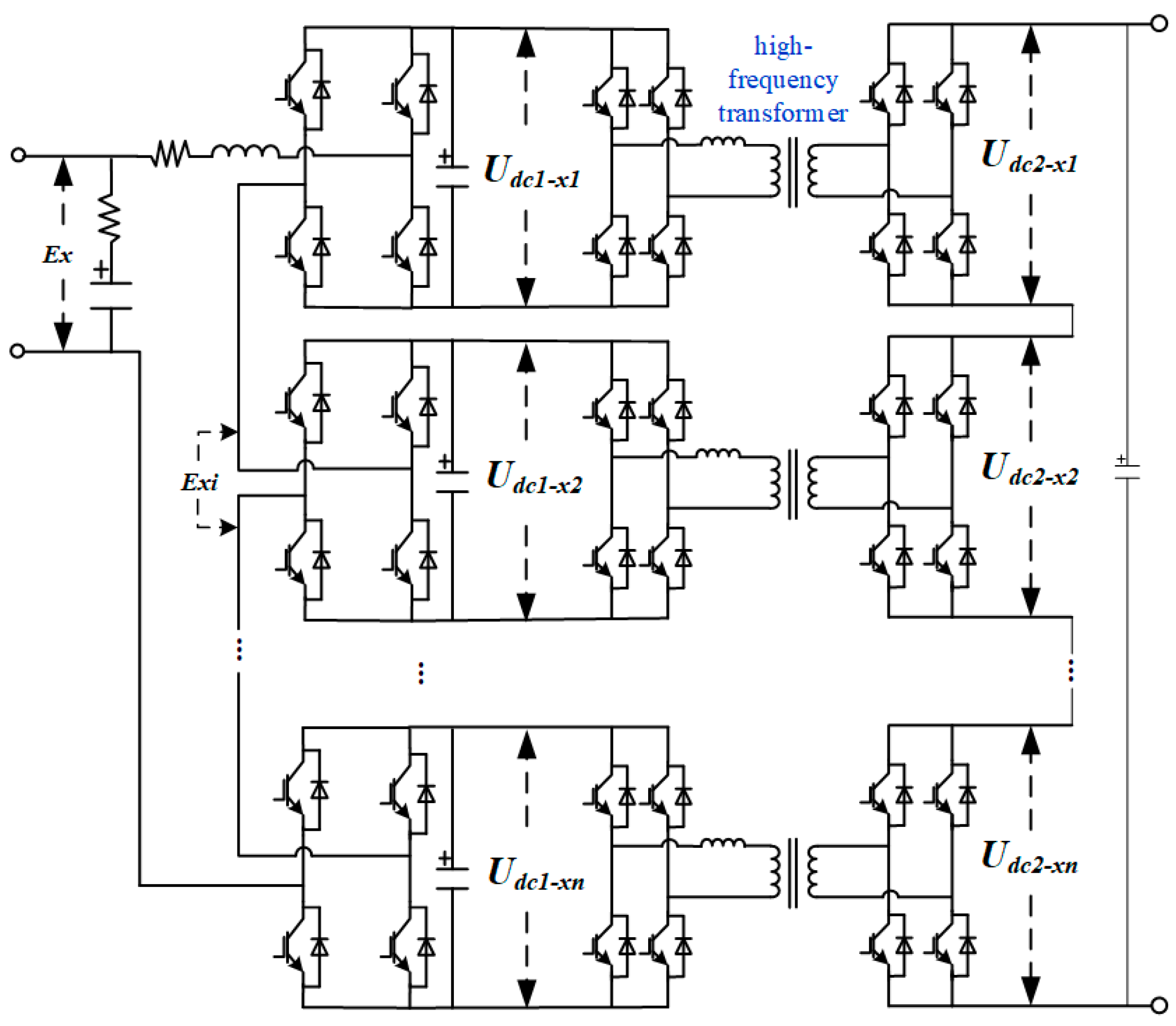
2.1. High-Voltage Side Topology

The high-voltage side topology is composed of cascaded H-bridges and isolated DC/DC converters. The topology is shown in Figure 2. The capacitance of medium-voltage DC side is designed according to [25]. As we all know, the larger the capacitance, the better it is to reduce the voltage ripple and improve the power quality. However, if the capacitance is too large, the current conduction angle will be small. Under the same output power, the effective value of the ripple current flowing through the capacitor will increase, which is the root cause of loss and heating of the capacitor. Based on this, capacitance of medium-voltage DC side is set to 1000 μF in this paper.
Based on the Kirchhoff’s voltage law, the mathematical model can be obtained as:
{ E x i = S k U d c 1 x i E x = L s d i x d t + R s i x + i = 1 n E x i ,
U d c 2 x i = S k 1 S k 2 k U d c 1 x i ,
where Ex is the grid voltage (x = a, b, c), ix is the grid currents, Exi is the AC voltage of the i-th cascaded H-bridge, Udc1-xi and Udc2-xi are pre-stage voltage and post-stage voltage of the i-th isolated DC/DC converter, Sk is switching function of cascaded H-bridge, Ls and Rs are equivalent inductance and resistance on the grid side, Sk1 and Sk2 are the switching functions of the pre-stage and post-stage of the isolated DC/DC, and k is the ratio of high frequency transformer. According to Equation (1), the output voltage of the DC side can be adjusted by changing Sk so as to realize the electric energy conversion between AC voltage and DC voltage. According to Equation (2), the output voltage of the low-voltage DC side can be adjusted by changing Sk1, Sk2 and k.
The transmission power PDC/DC of the isolated DC/DC converter is:
P D C D C = U d c 1 x i U d c 2 x i 2 k π f s L m δ ( 1 | δ | π ) ,
where fs is switching frequency, Lm is the leakage inductance of high-frequency transformer, and δ is the pulse shift angle. The transmission power can be adjusted by changing δ.
Compared with conventional converters, the multi-module topology has great advantages. The voltage and current change rate of bridge arm can be reduced by the cascade structure, which makes the sub-modules not need to be turned on and off at the same time. Therefore, the stress on the switch device decreases greatly, and the total output voltage distortion rate is greatly reduced. Meanwhile, the high-frequency transformer has a great attenuation effect on high frequency harmonics. The noise of the power grid will also be isolated by the transformer. It can avoid mutual interference between the grid side and secondary side.

2.2. Low-Voltage Side Topology

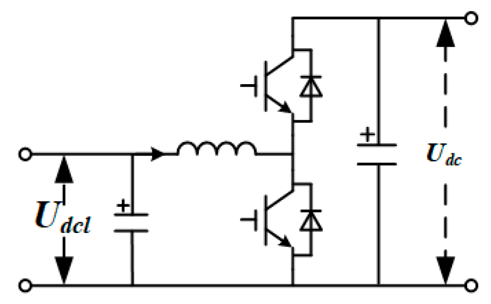
2.2.1. DC/DC Converter

The DC/DC converter adopts a non-isolated Buck/Boost structure. The topology is shown in Figure 3. The design of the LC filter follows the principles proposed in [25]. Meanwhile, the resonance frequency of the LC filter is less than 1/6 of the sampling frequency. Therefore, the parameters of the LC filter designed in this paper can ensure the stability of the system and have sufficient control bandwidth [26].
The low-voltage side (Udcl) of the DC/DC converter is connected to the new energy module, and the medium-voltage side (Udc) is connected to the medium-voltage DC bus. When the new energy module supplies power to the DC bus, the DC/DC converter works in Boost mode, which can increase the voltage of the new energy module and output a stable DC voltage. When the power grid charges the energy storage module, the DC/DC converter works in Buck mode, which can convert the DC bus voltage into the working voltage of the energy storage module. The output voltage can be expressed as:
U d c l = D U d c 1 D ,
where D is the duty ratio of the converter. The non-isolated Buck/Boost structure is simple, which has a relatively small number of power switches. The bidirectional energy flow can be realized through the fully controlled switching devices and reverse parallel diodes. Moreover, the conversion efficiency is high. It is suitable for new energy sources that do not require isolation.

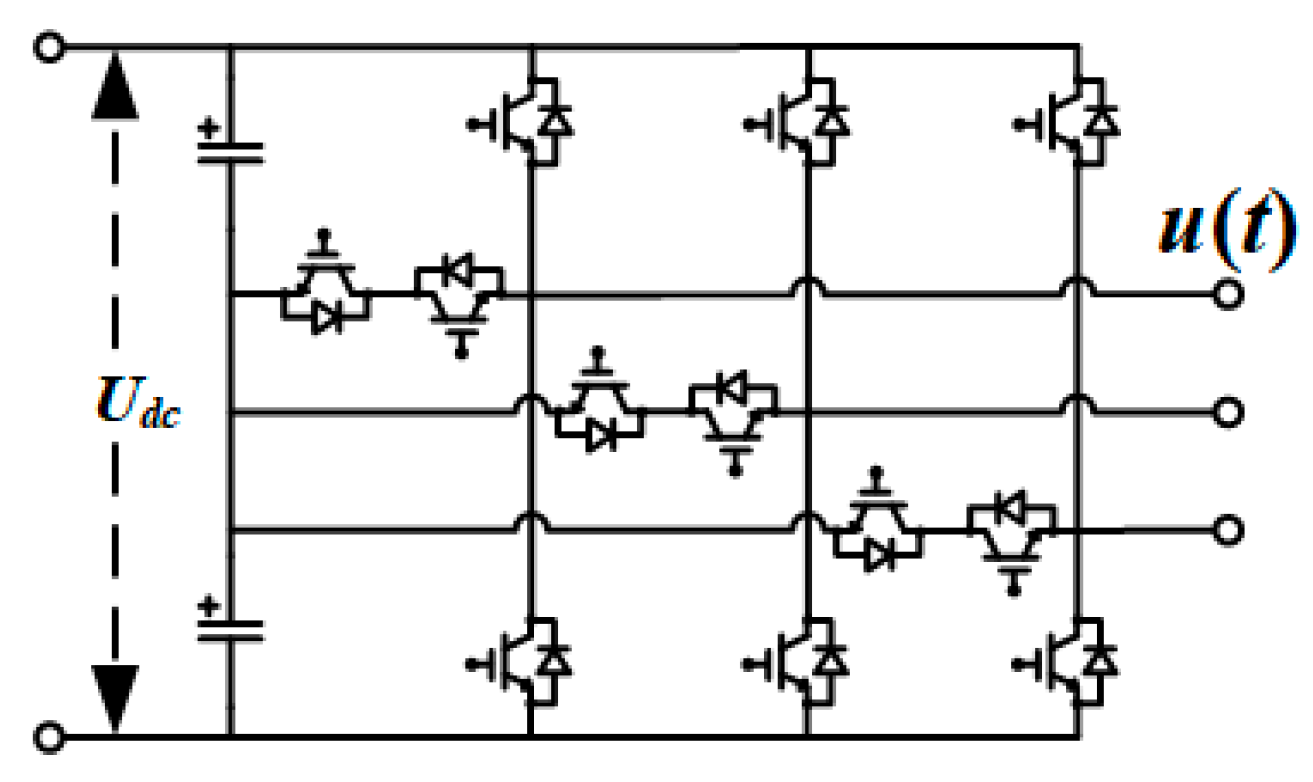
2.2.2. DC/AC Converter

The DC/AC converter adopts a three-level structure. The topology is shown in Figure 4.
The output voltage is:
u ( t ) = U d c 2 ( d x + n x ) ,
where dx is the duty ratio and nx is the benchmarking function for the conversion between three switch-status of three-level inverter, which can be expressed as:
n x = { 1 ,         O P O 0 ,         N O N .
Compared with the traditional two-level topology, the three-level inverter can output voltage with lower harmonic content and better power quality.

3. Operation Modes of Distribution Area

Due to the access of new energy power sources, the power supply of the distribution area has changed from a single power supply to joint power supply of new energy sources and power grid. The distribution area shall have priority to absorb the power of new energy. Therefore, the operation mode of the distribution area can be divided into the following four modes. The energy flow of each mode is shown in Figure 5.

3.1. Grid-Connected Operation Mode

When new energy module has no energy supply, the distribution area runs in grid-connected operation mode. The energy in the distribution area is all supplied by the grid. The power grid provides power for AC loads and DC loads and charges for energy storage. The power relationship between each module is as follows:
{ P p g = P d l + P a l ( P n e + P b a t ) P n e = 0 P b a t < 0 ,
where Ppg is the power between grid and medium-voltage DC bus, and the positive direction of Ppg is the direction in which power flows from the grid to the distribution station area. Pdl is the DC load’s power, Pal is the AC load’s power, Pne is the power of new energy sources, Pbat is the charge and discharge power of energy storage, and the positive direction of Pbat is the direction of power when the battery is discharged.

3.2. Grid Support Operation Mode

When the new energy source is insufficient to support the power demand, the distribution area runs in grid support operation mode. The grid will supplement the required energy. The power relationship between each module is as follows:
{ P p g = P d l + P a l ( P n e + P b a t ) P n e > 0 , P b a t > 0 P p g > 0 .

3.3. New Energy Feed Operation Mode

New energy feed operation mode is the mode in which new energy sources feed power to the grid. The new energy module gives priority to the load to supply power. The new energy module feeds power to the grid when the energy is surplus. This mode can support the stability of grid voltage and frequency when there is a voltage or frequency drop in the power grid. The power relationship between each module is as follows:
{ P p g = P d l + P a l ( P n e + P b a t ) P n e > 0 , P n e + P b a t > 0 P p g < 0 .

3.4. Isolated Operation Mode

The isolated operation mode is the mode in which all electric energy in the distribution area comes from new energy. At this time, it is necessary to control the output power of energy storage to ensure the energy balance in the distribution area. In addition, when there is a fault on the grid side or the new energy in the distribution area can be self-dissipated, the distribution area runs in isolated operation mode. The power relationship between each module is as follows:
{ P p g = P d l + P a l ( P n e + P b a t ) P n e > 0 , P n e + P b a t > 0 P p g = 0 .

4. Control Strategy

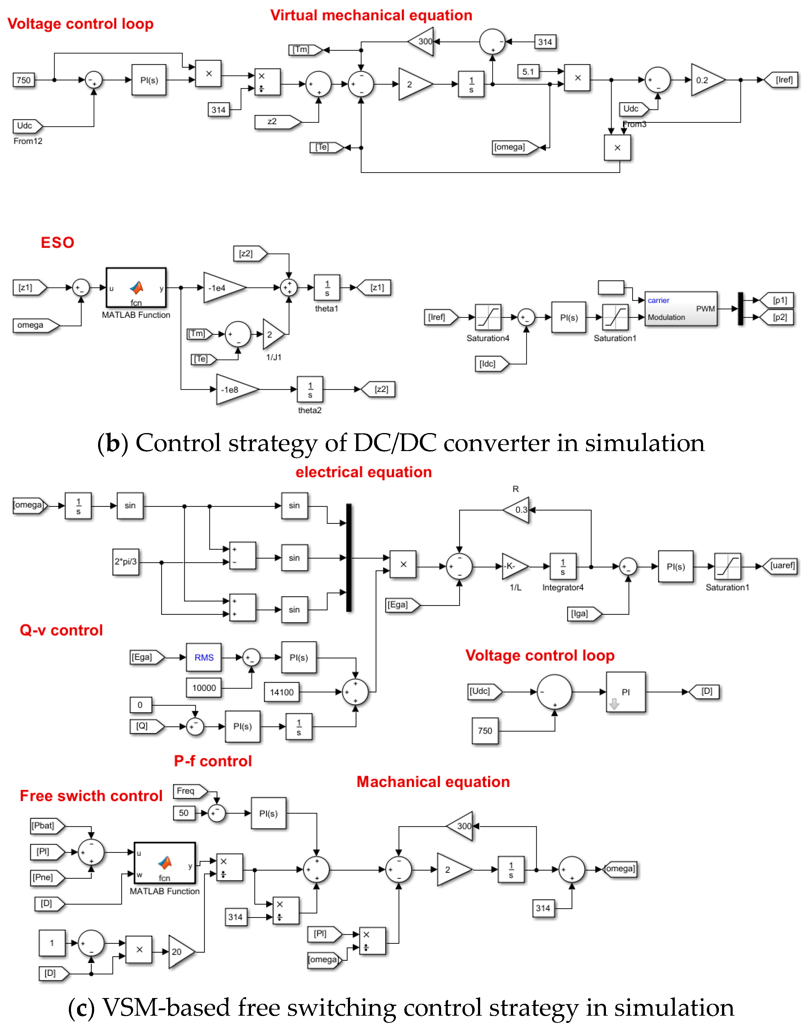
4.1. Control Strategy of DC/DC Converter

In the ER system, the continuous fluctuations of new energy will inevitably affect the stability of the system. However, the traditional converters do not have inertia and damping characteristics, which cannot effectively suppress disturbances. In this case, the stability of the DC bus voltage cannot be guaranteed, which will result in a decrease in power quality. To overcome this limitation, the ESO and a VSM control strategy based on the DC machine is proposed for the DC/DC converter to keep the DC bus voltage stable and improve the robustness of the system.
By introducing the mathematical model of the DC machine into the control of the converter, the VSM control strategy brings the inertia and damping characteristics of the DC machine to the system. Specifically, the DC bus voltage of the DC/DC converter is controlled by simulating the electromotive force balance equation and mechanical equation of the DC machine. In this way, the DC/DC converter has external characteristics like those of a DC machine. The electromotive force balance equation of the armature circuit of DC machine can be expressed as:
E = U + I R a ,
where E = CTΦω is armature voltage, CT is torque coefficient, Φ is magnetic flux, Ra is armature resistance, and U and I are the equivalent output voltage and current of the DC machine.
The electromagnetic power of DC machine is:
P e = E I ,
The mechanical equation of DC machine is:
J ω ˙ = T m T e D p ( ω ω 0 ) ,
where Tm is mechanical torque, Te = Pe/ω is electromagnetic torque, J is the virtual moment of inertia, Dp is the damping, ω0 and ω is rated angular frequency and electrical angular frequency.
As shown in Figure 6, by introducing the electromotive force balance equation and virtual mechanical Equations (11)–(13) of the DC machine into the voltage loop control of the DC/DC converter, the output of the DC/DC converter has similar output characteristics to the DC machine. On the one hand, due to the existence of J, the converter has inertia in the power and frequency dynamic process. On the other hand, due to the existence of Dp, the converter can dampen the grid power oscillation. Therefore, the VSM control strategy can enhance the inertia and damping characteristics of the DC/DC converter system and improve the stability of the DC bus voltage. The parameters of J and Dp can be designed according to [27,28]. By analyzing the frequency drooping and regulation of active power related to VSM, active power loops and reactive power loops are decoupled. Based on this, J and Dp are set to 0.5 kg·m2 and 300 N·m·s/rad.
In addition, due to the unpredictability of new energy and load disturbances, the ESO is extended to VSM control in this paper to further improve control performance. The design process of ESO is as follows:
According to the principle of ESO [29], in the first order system with a state variable of x1, the disturbance of the system can be easily observed by expanding the disturbance to a new state variable x2. In this way, when the system is disturbed by the unpredictable fluctuations of new energy and loads, the ESO can comprehensively estimate all external disturbances. In this paper, the state variable x1 is set as ω. Therefore, the system of VSM control strategy can be expressed as:
{ x ˙ 1 = x 2 + 1 J T m x ˙ 2 = w ( t ) ,
where w(t) is the real-time action of the sum of disturbances to the system.
Then, a non-linear function is constructed according to Equation (14):
{ z ˙ 1 = z 2 β 1 g 1 ( e r r , α 1 , μ 1 ) + 1 J ( T m T e ) z ˙ 2 = β 2 g 2 ( e r r , α 2 , μ 2 ) ,
where β1 and β2 are the gain of the output error, z1 is the observed value of ω, and z2 is the estimated value of disturbance. It is necessary to select a suitable non-linear function g(z) to realize the accurate tracking of z1 to ω. Only in this way, the ESO can accurately calculate z2, which is fed back to the control system as the compensation term for disturbance.
Thus, to improve the efficiency of state tracking of ESO, a continuously differentiable fak function is added in ESO:
f a k ( e , α , μ ) = | e | α 2 π arctan ( μ e ) ,
where e is tracking error and α and μ are nonlinear factors. The fak function is continuous and derivable, so the response speed and stability of the system can be improved. According to [30], the value range of α is (0,1), and the values of α and u determine the tracking speed and filtering effect. To improve the compensation effect for disturbance, α and u are set to 0.6 and 5000 [31].
Submitting the fak function into the g(z) in (15), the designed ESO can be obtained as:
{ e = z 1 x 1 z ˙ 1 = z 2 β 1 f a k ( e , α , μ ) + 1 J T m z ˙ 2 = β 2 f a k ( e , α , μ ) ,
The values of β1 and β2 can be designed by the “bandwidth method” [31]. In this paper, β1 = 1 × 10⁴, β2 = 1 × 10⁸. Through the observation, estimation, and compensation of disturbances by ESO, z1 can track the value of ω. Then z2 is calculated as a virtual torque compensation term and fed back to the mechanical equation of the virtual DC machine to reduce the influence of disturbances on system stability. Therefore, the proposed control strategy can better cope with the fluctuation of new energy and effectively support the stable operation of the distribution area.
According to Equations (11)–(17), the control strategy of virtual DC machine with ESO is obtained. The control structure of the control strategy is shown in Figure 6. The error between the reference value of DC bus Udcref and actual value Udc is sent into the PI controller to obtain the magnitude of the current, then multiplied with Udcref to obtain Pm. After dividing by ω0, the mechanical torque is obtained. Then, the z2 is used as the compensation term of the virtual torque to compensate for the disturbance and go through Equation (11) to obtain the reference current Iref. Finally, the switch tube is controlled by PI controller and modulation link. Thus, the voltage of DC bus is controlled.
The VSM control strategy provides inertia and damping characteristics for the power electronic converter, while the ESO plays a role in observing and compensating for the fluctuation of new energy sources. Therefore, the control strategy of the DC/DC converter can stabilize the voltage of DC bus better when the new energy source fluctuates and can effectively promote the anti-disturbance ability of the system.

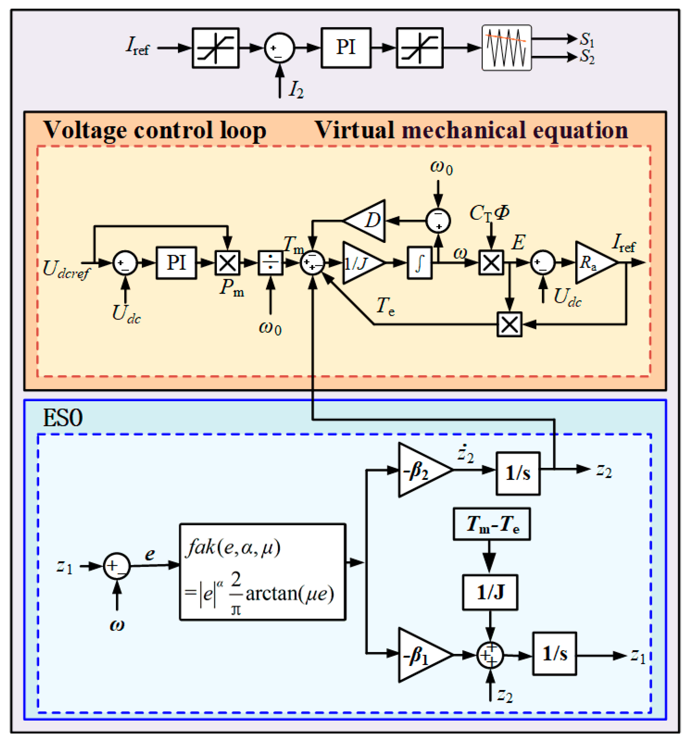
4.2. Free Switching Control Strategy for High-Voltage Side

To meet the requirements of multi-directional power flow in the ER system, the control strategy applied to the high-voltage side cascaded H-bridge needs to realize free switching between different operation modes. The control target is to achieve accurate tracking and active control of power.
Different from the VSM control strategy based on the DC machine in Section 4.1, the VSM control strategy based on the AC machine is applied in the control strategy of the cascaded H-bridge. The inductance and resistance on the AC side of the cascaded H-bridge can be equivalent to the synchronous inductance and resistance of the synchronous machine. Thus, the electrical equation of cascaded H-bridge can be derived as:
E x i = E x + R S i x i + L S d i x i d t .
Like Section 4.1, this formula and mechanical equation are introduced into the control of the cascaded H-bridge so that the system has external characteristics like the synchronous machine, which improves the stability of the system.
Furthermore, to achieve control of power, the active-frequency (P/f) control and reactive-voltage (Q/v) control are integrated in the cascaded H-bridge control strategy.
For the P/f control in the VSM control strategy, it is implemented according to the operating principle of traditional synchronous machine, which regulates the active output by adjusting the mechanical torque and realizes the response to the grid frequency deviation through the frequency modulator. Therefore, the P/f control realizes the adjustment of the active power command of the cascaded H-bridge by adjusting the virtual mechanical torque Tm of the VSM. For the Q/v control in the VSM control strategy, like the synchronous machine, the terminal voltage and reactive power are changed by adjusting virtual potential Ep of the VSM.
Compared with the traditional PQ control strategy, the P/f and Q/v control of VSM have superior control performance. Besides the accurate tracking of active power and reactive power, the VSM control strategy can also actively adjust frequency deviation and the voltage of the distribution network.
Based on the above control strategy, the active control of the power flow and accurate tracking of the reference power Pref can be realized. Further, to achieve the multi-mode operation of the proposed ER and the free switching between different modes, the reference power needs to be accurately calculated and automatically adjusted.
According to the power relationship between each module of the different operation modes in Section 3, the reference power of the cascaded H-bridge can be obtained as:
P r e f = P l ( P n e + P b a t ) ,
where Pl = Pal + Pdl. Combining the transmission power of the isolated DC/DC converter in Equation (3), the reference voltage at Udc1 can be obtained:
U d c 1 r e f = [ P l ( P n e + P b a t ) ] 2 k f s L m D ( 1 D ) U d c ,
where D = δ/π is the duty ratio of the converter. Then, through the DC voltage controller and combined with the reference voltage Udc1ref, the power adjustment amount ΔP can be obtained. Based on this, the total power required by the high-voltage side can be obtained as:
P s e t = Δ P + P r e f .
With the above method, the reference power in the VSM control strategy can be automatically changed according to the power flow during actual operation. Without changing the control strategy, the proposed control strategy can meet the power flow demand in each operation mode, which improves the stability and reliability of the system.
In summary, combining Equations (18)–(21), the free switching control strategy using VSM for cascaded H-bridge is obtained.
The complete control structure of the high-voltage side is shown in Figure 7. The inputs of control are Ex, Udclref, Ppg, Qpg, and f. The outputs are drive signal required for the converter. The outer control of the cascaded H-bridge is power control. After calculating Pset, the P/f control and the Q/v control are performed. The inner control is VSM control, the virtual angular frequency ω is obtained through the virtual mechanical equation, and then, Uxref is obtained through the virtual electrical equation. Finally, after the carrier shift term sinusoidal pulse width modulation strategy, the drive signal required by the power electronic converter is output. Meanwhile, the post-stage of isolated DC/DC converter uses voltage loop control, and the pre-stage modulates the DC signal into a square wave with a duty ratio of 50%. After passing through the post-stage of the transformer, it is rectified back to the DC signal.
To sum up, the VSM control strategy and ESO are applied in a cascaded H-bridge and DC/DC converter to improve the stability of the system. For the three-level converter, this paper adopts a simple voltage–current double closed-loop control strategy [32]. Further, a free switching control strategy is proposed to realize free switching of different working modes, which is achieved by automatically changing the power reference according to the power flow. During the operation of the system, there is no need to change the control strategy, which improves the reliability of the system and load power supply.

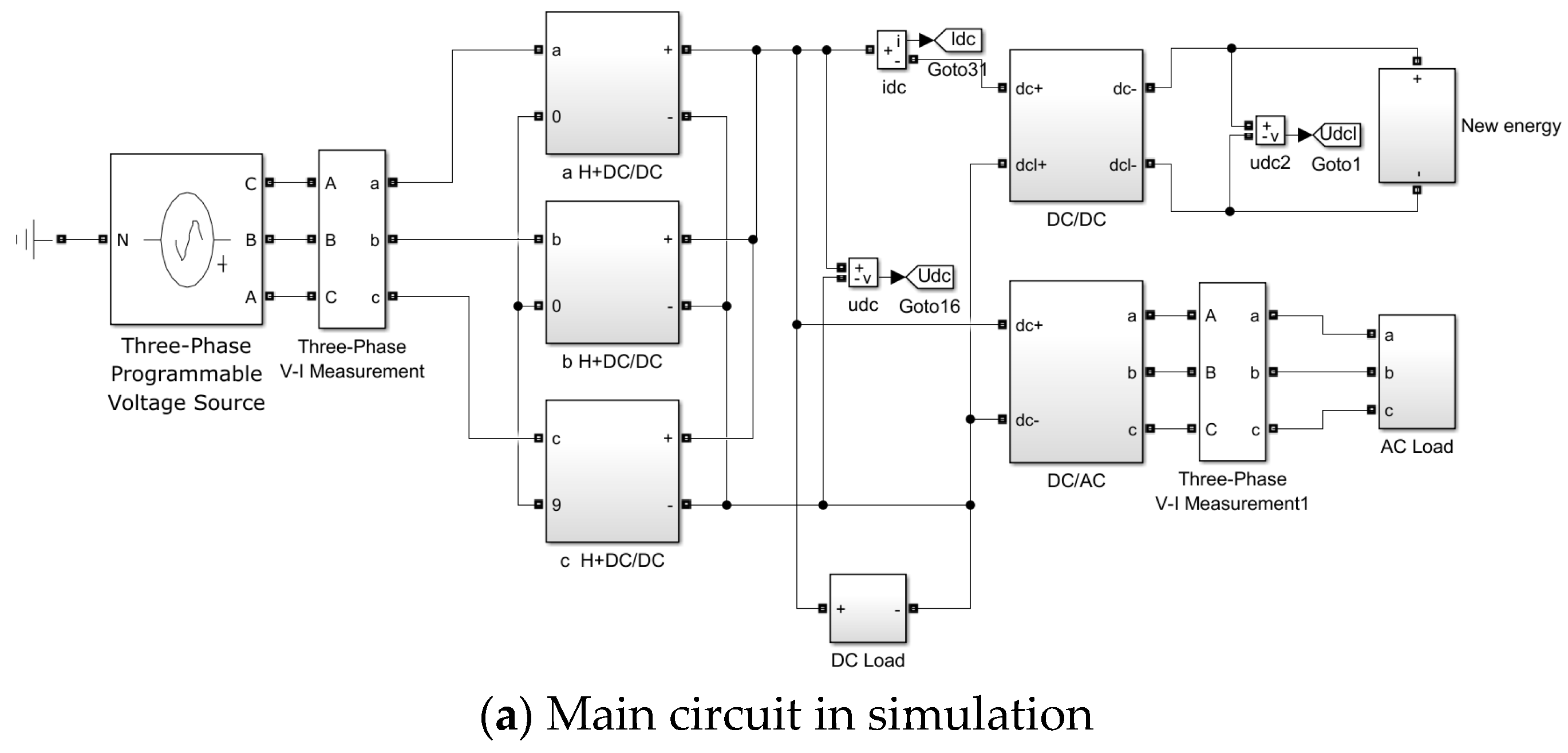
5. Simulation and Experimental Results

To validate the performance of proposed scheme, both simulation and experiment are performed. The key parameters of the system and control strategy are listed in Table 1. The rated voltage of Udc, u(t), and E(t) are selected from the common voltage levels of the power system [33,34,35,36].

5.1. Simulation Results

The simulation model of the proposed ER system and control strategy is shown in Figure 8, which is established by MATLAB/Simulink. As shown in Figure 8a, the main circuit of the ER model includes high-voltage side topology (cascaded H-bridge and isolated DC/DC converter), three-level inverter, DC/DC converter, AC/DC loads and new energy, which are consistent with Figure 1. In Figure 8b, the control strategy of the DC/DC converter established according to Figure 6 is shown in detail, which is a VSM control strategy based on a virtual DC machine with ESO. The VSM-based free switching control strategy applied to the high-voltage side established according to Figure 7 is shown in Figure 8c, which includes P/f control, Q/v control, free switching control, and VSM control.

5.1.1. Single Mode Simulation Results

Case 1: Overload operation in the new energy feed operation mode and the grid support operation mode. The simulation results are shown in Figure 9:
In Figure 9, the dynamic performance of the proposed control strategy is verified when the system is operating in the above two modes. Since the mechanical equation and electromotive force balance equation of the synchronous machine are applied to the DC bus voltage control, the system has the inertia and damping characteristics of the synchronous machine. Therefore, when the load changes from full load (100 kW) to overload (110 kW), the proposed control strategy can keep the DC bus voltage stable and efficiently supply power to the load.
Furthermore, because the power provided by the new energy remains unchanged, when the load increases, the energy feed to the grid by the distribution area is reduced, as shown in Figure 9a. Similarly, when the system is operating in grid support operation mode in Figure 9b, the increased power of the load is supplied by the grid. Therefore, the increase in load power is the same as grid power. In summary, the simulation results are in good agreement with Equations (8) and (9), which verify the correctness of the theoretical analysis.
Case 2: Grid voltages drop in the grid-connected operation mode. To verify the stability of the proposed ER system when the grid voltage drops, the grid voltage drops by 40% at 0.5 s and lasts for 10 cycles. The simulation results are shown in Figure 10.
Since the system is all power by the grid when running in grid-connected operation mode, the voltage drop of the power grid has the greatest impact on the system at this time. Fortunately, the VSM control strategy applied in this paper provides inertia and damping to the system. Specifically, on the one hand, due to the existence of J (virtual moment of inertia), the system has inertia in the dynamic response process of power and frequency. On the other hand, due to the existence of Dp (damping), the system can dampen grid power fluctuations. It can be seen from Figure 10 that, when the grid voltage drops or rises, both the DC bus voltage and AC output voltage have a small degree of distortion. However, they can restore stability in a very short period. The system can quickly restore stability while maintaining superior power quality.
Case 3: The random fluctuation of new energy in isolated operation mode.
In practice, the random fluctuation of new energy will affect the stability of the system, which has the greatest impact on isolated operation mode especially. Thus, the simulation of the impact of new energy fluctuation on the system is carried out in isolated operation mode. The simulation results are shown in Figure 11.
In this paper, the ESO is introduced into VSM control, which can estimate the disturbance to compensate for virtual torque. Therefore, the stability of the system is significantly improved. It can be clearly seen from Figure 11a that the voltage of the medium-voltage DC bus is not affected by the fluctuation of the new energy, which reveals that the proposed control strategy can effectively suppress the impact of the fluctuation of the new energy on the system. Meanwhile, as shown in Figure 11b, the enhancement of system stability can also improve the quality of the AC output voltage (THD = 1.74%). Even if the new energy source fluctuates, the system can still supply the load stably.

5.1.2. Simulation Results of Free Switching Control Strategy

To verify the proposed free switching strategy of the ER and the transient response during the switching process, the system is set to switch from isolated operation mode to new energy feed operation mode at 0.4 s, switch to grid support operation mode at 1.2 s, and switch to grid-connected operation mode at 2 s in the simulation. The power flow of each mode set by simulation is shown in Table 2. The simulation results are shown in Figure 12.
Figure 12a shows the DC bus voltage, grid-side currents, grid-side power, new energy power, and load power when the operating mode is switching. Figure 12b shows the THD of AC output voltage. As can be seen from Figure 12a, when any operation mode is switched, the DC bus voltage can be kept constant. The system initially operates in isolated operation mode, and the system is all powered by new energy sources. When switching from isolated operation mode to new energy feed operation mode, the high-voltage side of the ER is put into operation. The grid-side currents can quickly track the reference current, and the grid absorbs 20 kW of power. When switching from new energy feed operation mode to grid support operation mode, the grid currents are reversed instantaneously. The power grid changed from absorbing power to outputting 80 kW of power, and it remained stable in a short period of time. Meanwhile, the time required for switching is less than 0.1 s, and the power can be kept constant after switching. Finally, the system changes to grid-connected operation mode, new energy sources stop generating power, and all loads are supplied by the grid. In addition, in the entire mode switching process, the AC output voltages have always maintained a good power quality. It can be seen from the Figure 12b that the THD of the AC output voltage is 2.33%, which can maintain a good waveform.

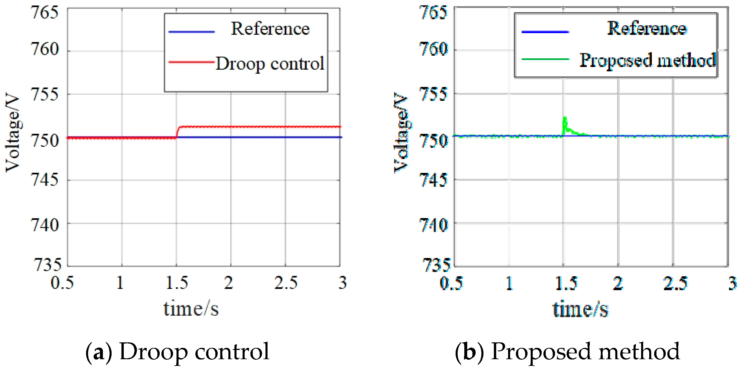
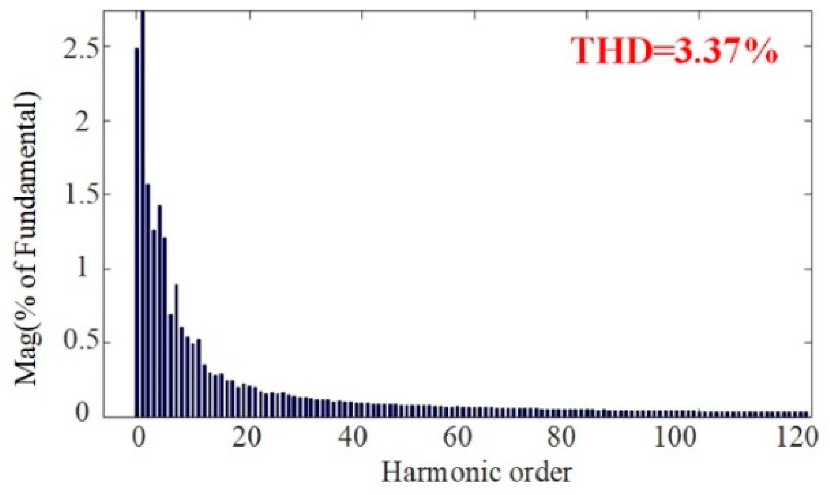
5.1.3. Simulation Results for Performance Comparison

To further verify the effectiveness of the proposed method, the proposed method is compared with the existing related control methods, which are all used to ensure stable operation of multi-port energy routers under different working conditions and operation modes. Therefore, the droop control method [18] and the traditional VSM control method [17] are selected as the benchmark work for the performance comparison. The simulation results are shown in Figure 13 and Figure 14.
Figure 13 shows the simulation results when the load is suddenly reduced by 10 kW. As shown in Figure 13a, when the droop control is adopted, the change in the load will cause the DC voltage to increase and cannot be restored to the reference value. The reason is that droop control has no inertia and damping characteristics, and the system characteristics become differential regulation, which will cause errors between the output of the system and the reference value. Therefore, the DC bus voltage cannot accurately track the reference value. More importantly, in this case, if the error exceeds the allowable range, it may even cause the ER to fail to meet the grid connection requirements and seriously affect the power supply to the load.
On the contrary, as shown in Figure 13b, when the proposed method is adopted, the inertia and damping characteristics given to the system improve the stability of the system. Therefore, when the load suddenly decreases, the DC bus voltage will quickly return to the reference value after a short and small fluctuation.
Figure 14 shows the simulation results of the traditional VSM control when the new energy fluctuates. Since the traditional method does not have ESO, compared with Figure 11b, the THD of the AC output voltage is increased from 1.74% to 3.37%. The simulation result proves that ESO can effectively observe, calculate, and compensate for disturbance items and feed the compensation term back to the control strategy. Therefore, the stability and reliability of the system have been improved.

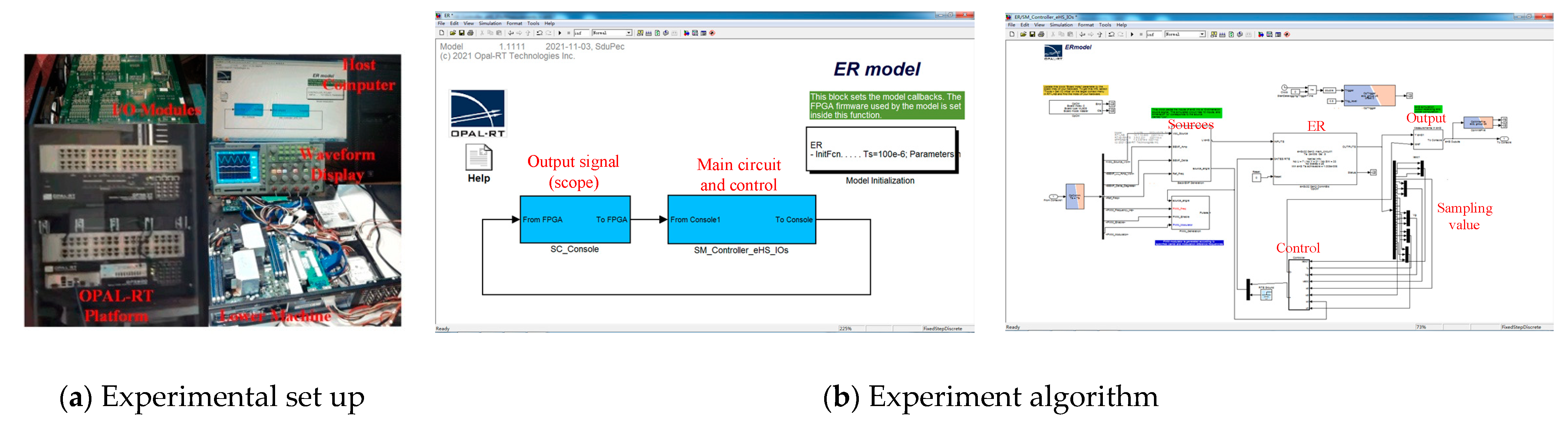
5.2. Experimental Results

The experimental set up and experimental algorithm are shown in Figure 15. To verify the effects of the proposed control method, the experiment was conducted using the OPAL-RT platform as shown in Figure 15a. The experimental algorithm of the proposed method is executed in this platform, and the practical feasibility of the proposed method is verified in the designed ER system, as shown in Figure 15b.

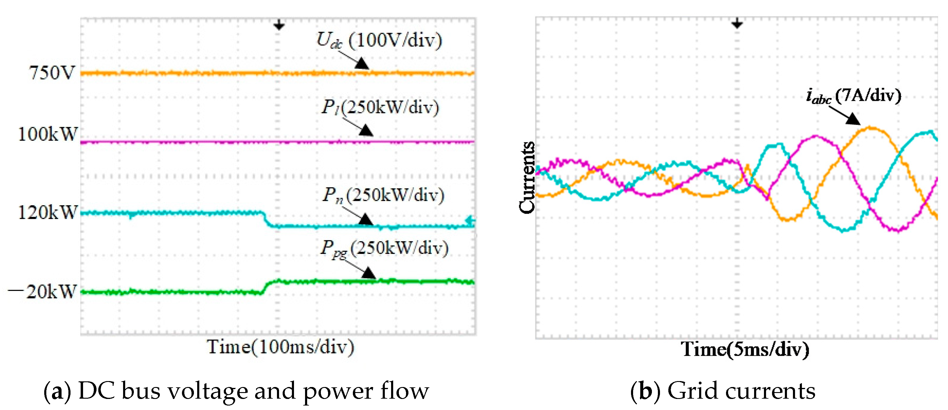
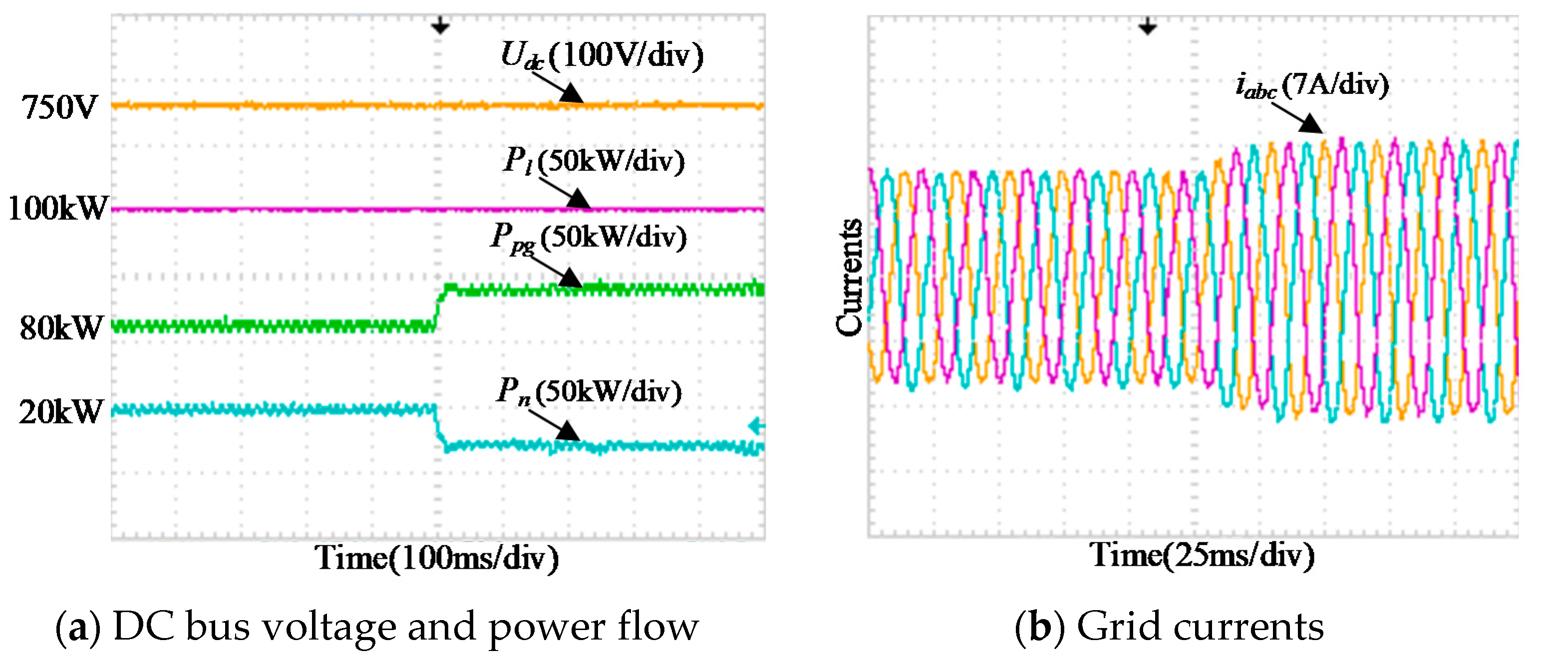
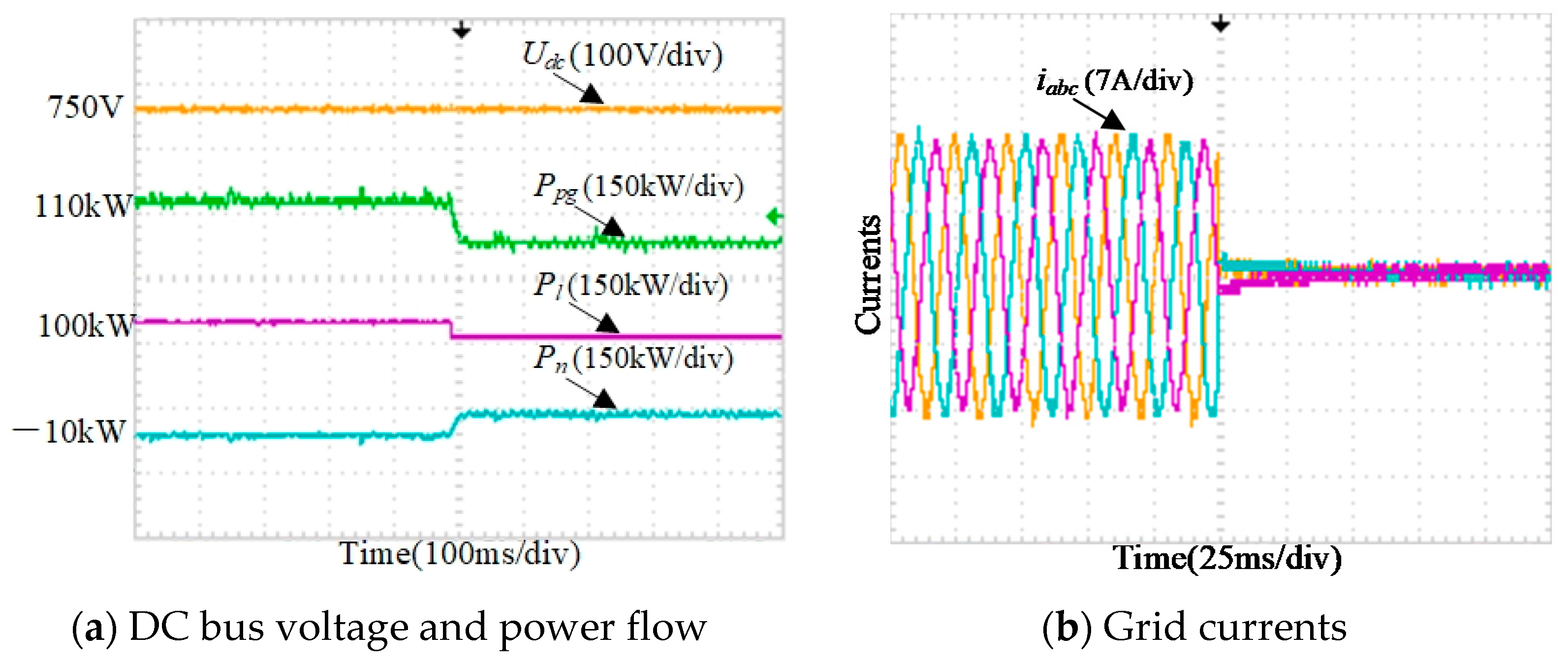
5.2.1. Single Mode Experimental Results

Case 1: Overload operation in new energy feed operation mode and grid support operation mode. The experiment results are shown in Figure 16, where Pn = Pne + Pbat is the power of new energy module.
Due to the inertia and damping characteristics introduced by the proposed VSM-based control strategy with ESO, the stability of the system has been further improved. Therefore, as shown in Figure 16 when the load suddenly increases by 10% from the full load power, the medium-voltage DC bus voltage can remain stable. In addition, when the load power changes, the proposed control strategy will change the power absorbed or output by the grid to ensure power balance, which verifies the correctness of the theoretical analysis and control method in this paper.
Case 2: Grid voltage drops in grid-connected operation mode. The experiment results are shown in Figure 17.
When the grid voltage drops suddenly by 40%, the DC bus voltage and the low-voltage side AC bus voltage in the grid-connected operation mode are shown in Figure 17a,b. It can be clearly seen that the proposed control strategy can still ensure the stability of the DC bus voltage when the grid voltages drops. More importantly, the quality of the output voltages on the low-voltage AC side is also maintained (THD = 4.11%), which provides stable power to the load. Therefore, the control performance of the proposed control strategy is verified when the grid voltages drop.
Case 3: The random fluctuation of new energy in isolated operation mode. The experiment results are shown in Figure 18.
The medium-voltage DC bus voltage and the low-voltage side AC bus voltages at this time are shown in Figure 18a,b. Due to the application of ESO, the disturbances of new energy sources can be fed back to the control system to reduce the influence of disturbances on system stability. Therefore, as shown in Figure 18b,c, even when the new energy source fluctuates, the quality of the medium-voltage DC bus voltage and the output voltages of the low-voltage AC side is guaranteed.

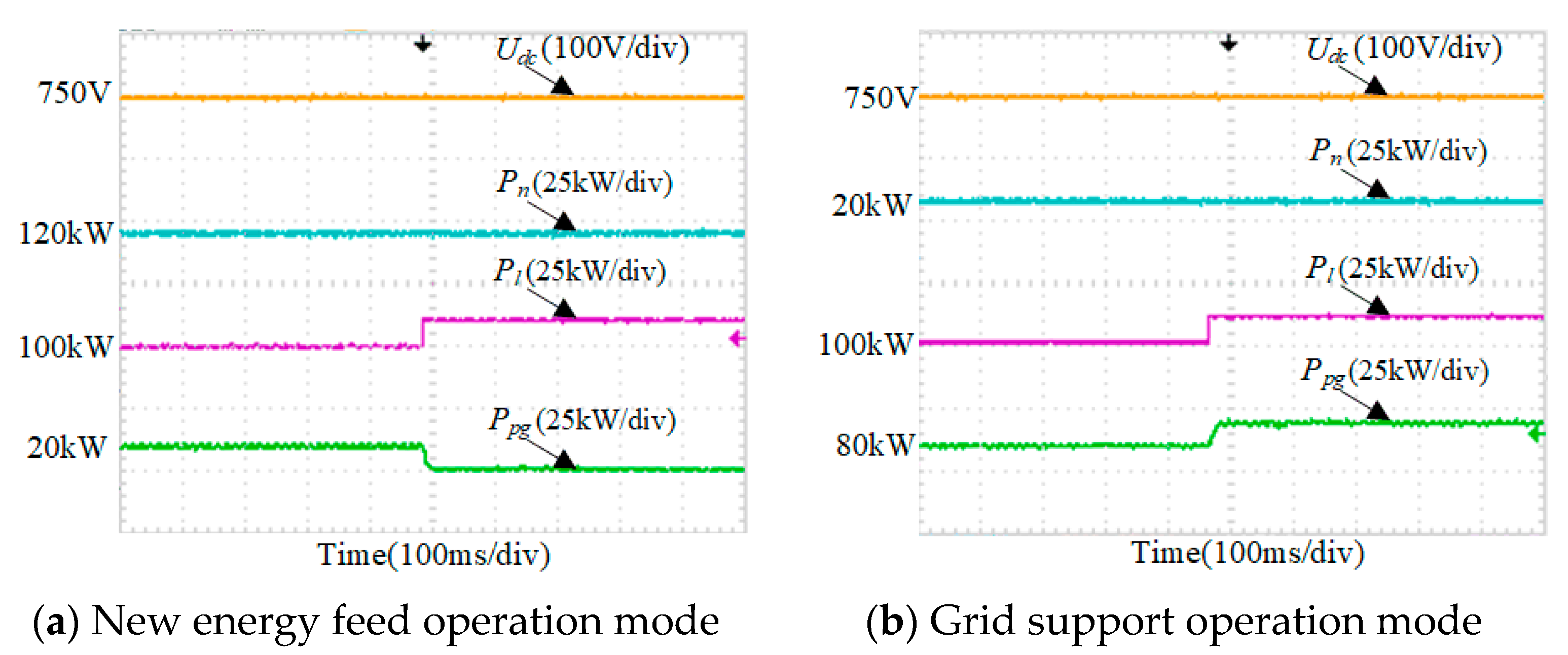
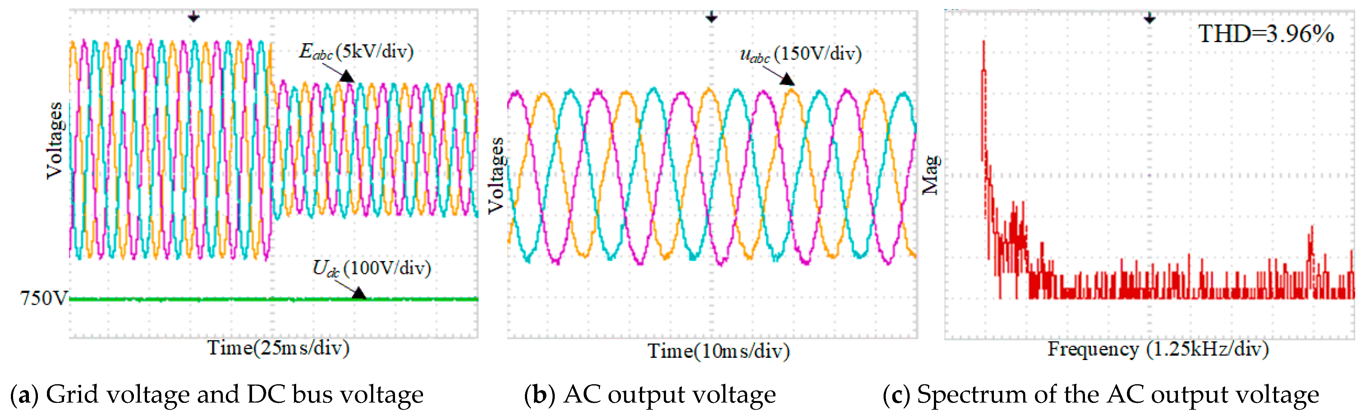
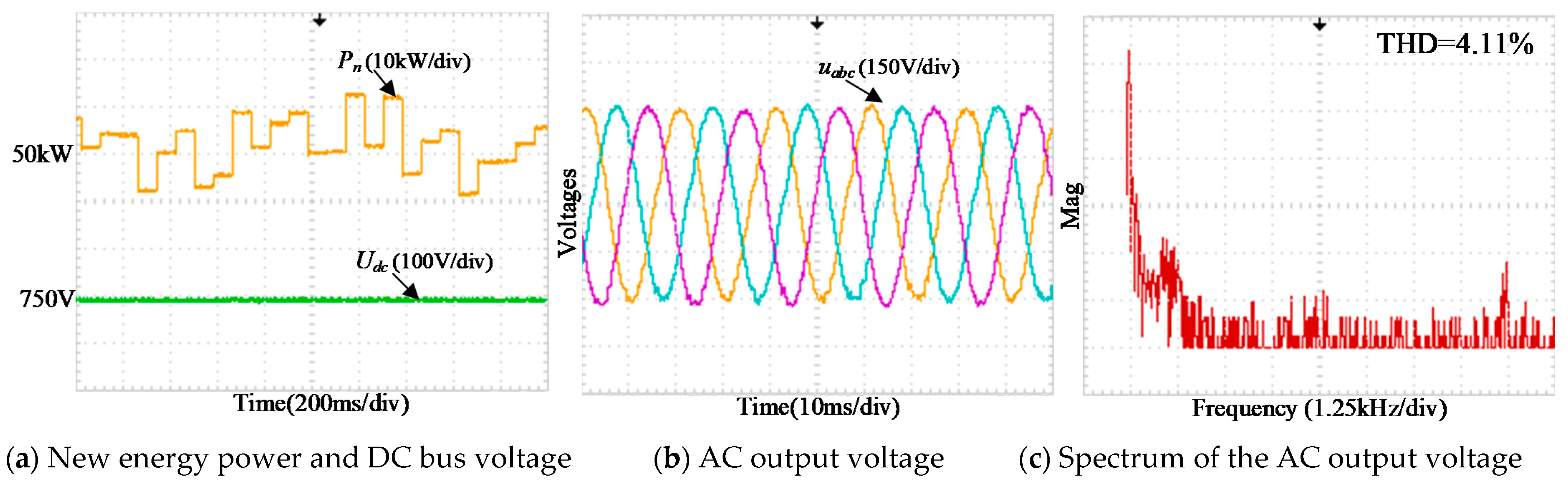
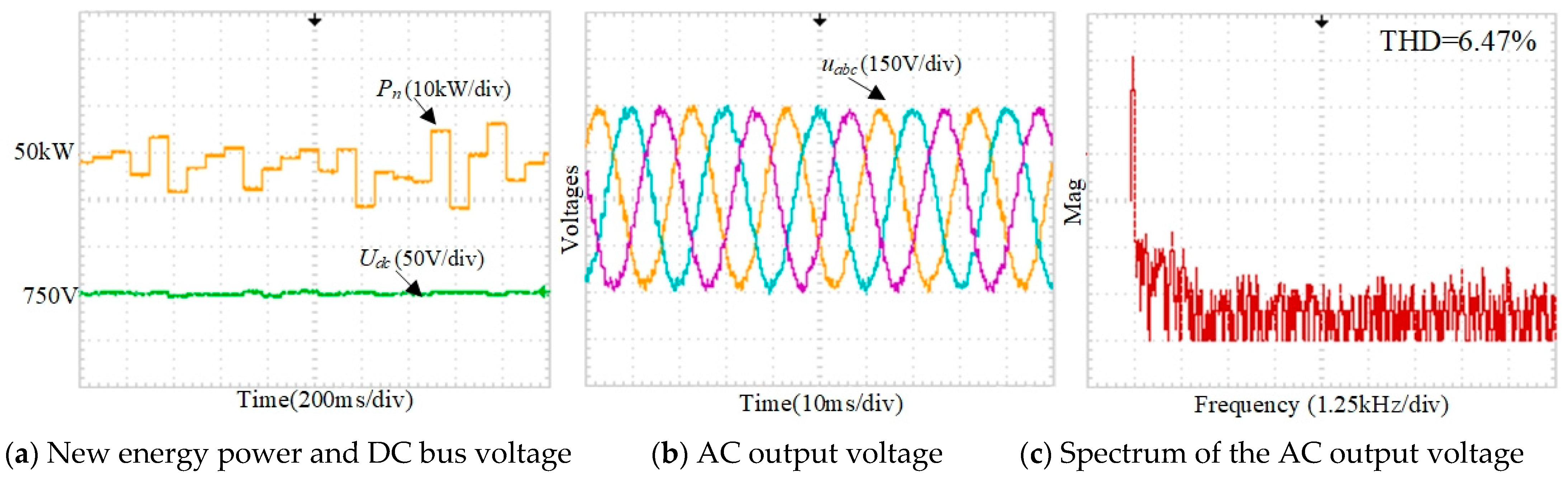
5.2.2. Experimental Results of Free Switching Control Strategy

To verify the effectiveness of the proposed VSM-based free switching control strategy, the experimental results of switching between different operations modes are shown in Figure 19, Figure 20 and Figure 21. The power flow of each operation mode is the same as Table 2.
It can be seen from Figure 19a that when the output power of the new energy is reduced, the system switches from the new energy feed operation mode to the grid support operation mode. At this time, as shown in Figure 19b, the direction of the grid currents is reversed, and the grid outputs 80 kW of power. When the system switches from grid support operation mode to grid-connected operation mode, as shown in Figure 20a, the new energy module changes from output power to energy storage. Therefore, the power output from the grid needs to be further increased to 110 kW. In Figure 21, the system switches from grid-connected operation mode to isolated operation mode, and all loads are powered by new energy sources. Therefore, the grid output power and currents are changed to zero, and the load power is the same as the new energy power. Furthermore, it can be clearly seen from Figure 19, Figure 20 and Figure 21 that the DC bus voltage can remain stable and the quality of the grid currents is good during the transient process of various mode switching.

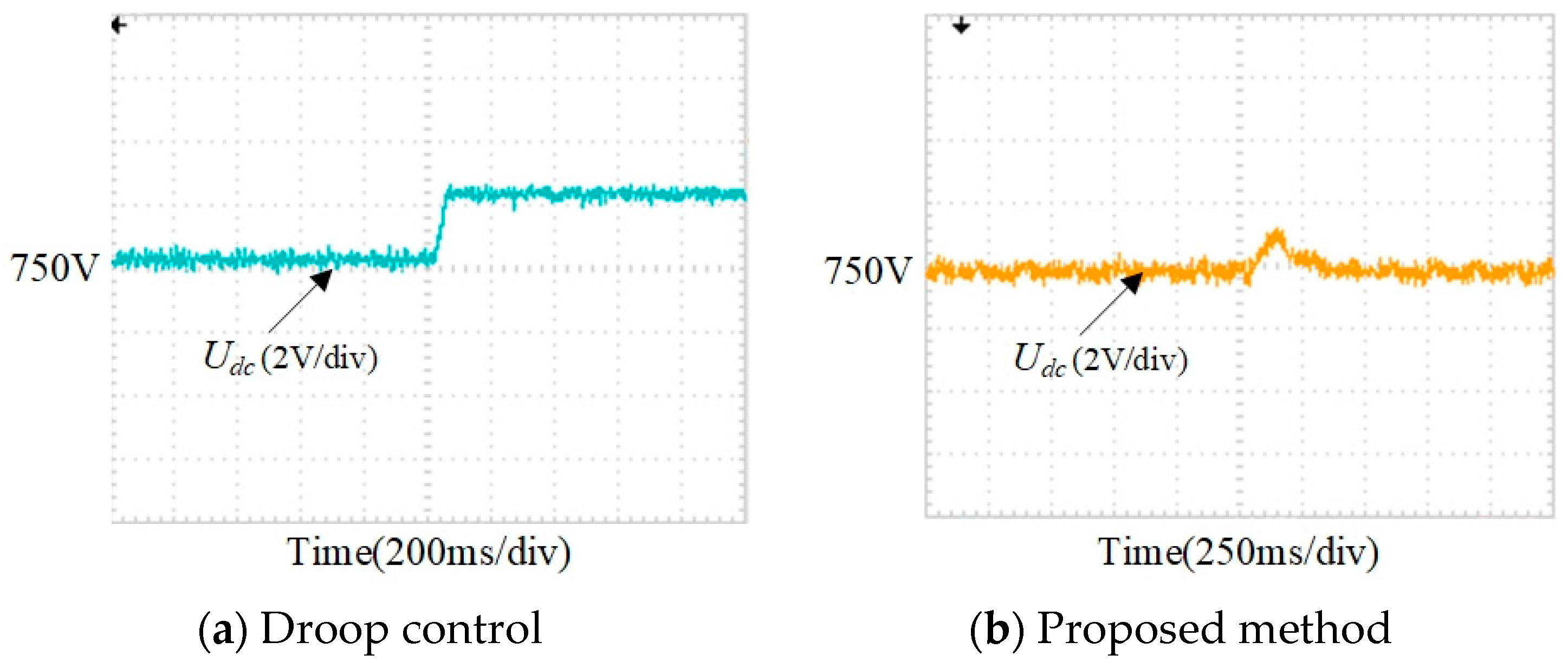
5.2.3. Experimental Results for Performance Comparison

To verify the effectiveness of the proposed method, the proposed method is compared with droop control and traditional VSM control. The experiment results are shown in Figure 22 and Figure 23.
As shown in Figure 22a, due to the differential adjustment characteristics of droop control, when the load suddenly decreases, the DC bus voltage cannot remain stable at the reference value. On the contrary, the proposed method can provide effective inertia and damping characteristics for the system. Therefore, the proposed method can quickly stabilize the bus voltage in Figure 22b when the load is suddenly reduced. Furthermore, comparing Figure 18 and Figure 23, when the traditional VSM control without ESO is applied, the THD on the low-voltage AC side increased from 4.11% to 6.47%, and the ripple of the DC bus voltage is increased. The experimental result proves that ESO can compensate well for system disturbances when new energy sources fluctuate and improve the power quality of the system.
It is worth noting that there are some differences in power quality between experimental results and simulation results. For example, compared with the simulation results in Figure 12, the power fluctuations in Figure 19, Figure 20 and Figure 21 of the experimental results are increased. The differences are caused by the different working conditions of simulation and experiment. The simulation is based on ideal conditions, and the experiment is based on actual experimental equipment. Specifically, there are two main reasons. On the one hand, the actual hardware system itself is composed of various power electronic devices; inevitably, there are parasitic resistance, parasitic capacitance, stray inductance, and other unfavorable factors that affect the experimental results. On the other hand, the external environment will have various uncertain interferences on the experimental results, such as electromagnetic interference (EMI), electromagnetic susceptibility (EMS) of electronic equipment, noise, temperature, and humidity, etc., which will affect the power quality during actual operation. However, it can be seen from the simulation and experimental results that they are qualitatively the same and only slightly different in quantitative terms. These differences are inevitable in actual operation and are within an acceptable range. Therefore, although the power quality of the experimental results is slightly lower than that of the simulation results, it can still meet the power grid operation requirements, and the effectiveness of the proposed method has been verified.
In summary, the proposed free switching control strategy can achieve free switching of different operating modes without changing the control strategy, which is achieved by automatically changing the power reference according to the power flow. At the same time, due to the introduction of VSM control strategy and ESO, inertia and damping characteristics are added to the system, which enhance the system’s ability to resist disturbances. Therefore, the system can quickly restore stability after switching between different modes.

6. Conclusions

In this paper, a free switching control strategy for multi-port ER is proposed, which is suitable for the distribution area with a high penetration rate of the new energy. Firstly, this paper designs the topology of multi-port ER. Moreover, the multi-operation modes and power flow of the distribution area are analyzed in detail. Based on this, the corresponding control strategy of ER is studied. To improve the acceptance capacity of new energy, ESO is introduced to control strategy of DC/DC converter based on the VSM control strategy. The ESO can observe the fluctuations of new energy and compensate them back to the control strategy after calculation. Meanwhile, aiming at different energy flows in multi-operation modes, a free switching control strategy is designed. This control strategy can accurately transmit the required power and maintain the stability of the DC bus voltage. Finally, the effectiveness of the proposed strategy is verified by simulation and experimental results. For simulation, it can test the effect of the proposed method in the designed ER system under ideal conditions. The experimental results verify the feasibility of the proposed method. The results prove that the designed ER can realize convenient access to the new power sources and flexible loads, and the proposed VSM-based free switching control strategy can effectively improve the robustness of the system and achieve smooth switching between different operating modes.

Author Contributions

Conceptualization, S.C. and Z.L.; data curation, L.L.; formal analysis, S.C.; investigation, L.L.; methodology, S.C. and Z.L.; project administration, Y.S.; resources, Y.S. and L.L.; supervision, Z.L.; visualization, Y.S.; writing—original draft, S.C.; writing—review and editing, S.C. and Z.L. All authors contributed to this work by collaboration. All authors have read and agreed to the published version of the manuscript.

Funding

This research received no external funding.

Data Availability Statement

Not applicable.

Conflicts of Interest

The authors declare no conflict of interest.

References

  1. Razi, R.; Pham, M.-C.; Hably, A.; Bacha, S.; Tran, Q.-T.; Iman-Enin, H. A Novel Graph-Based Routing Algorithm in Residential Multimicrogrid System. IEEE Trans. Ind. Inform. 2021, 17, 1774–1784. [Google Scholar]
  2. Shi, X.; Xu, Y.; Sun, H. A Biased Min-Consensus-Based Approach for Optimal Power Transaction in Multi-Energy-Router System. IEEE Trans. Sustain. Energy 2020, 11, 217–228. [Google Scholar] [CrossRef]
  3. Li, P.; Sheng, W.; Duan, Q.; Li, Z.; Zhu, C.; Zhang, X. A Lyapunov Optimization-Based Energy Management Strategy for Energy Hub with Energy Router. IEEE Trans. Smart Grid 2020, 11, 4860–4870. [Google Scholar] [CrossRef]
  4. Matko, V.; Brezovec, B. Improved Data Center Energy Efficiency and Availability with Multilayer Node Event Processing. Energies 2018, 11, 2478. [Google Scholar] [CrossRef] [Green Version]
  5. Hussain, S.M.S.; Aftab, M.A.; Nadeem, F.; Ali, I.; Ustun, T.S. Optimal Energy Routing in Microgrids with IEC 61850 Based Energy Routers. IEEE Trans. Ind. Electron. 2019, 67, 5161–5169. [Google Scholar] [CrossRef]
  6. Guo, H.; Wang, F.; Li, L.; Zhang, L.; Luo, J. A Minimum Loss Routing Algorithm Based on Real-Time Transaction in Energy Internet. IEEE Trans. Ind. Inform. 2019, 15, 6446–6456. [Google Scholar] [CrossRef]
  7. Naseem, N.; Cha, H. Quad-Active-Bridge Converter with Current Balancing Coupled Inductor for SST Application. IEEE Trans. Power Electron. 2021, 36, 12528–12539. [Google Scholar] [CrossRef]
  8. Yun, C.G.; Cho, Y. Active Hybrid Solid State Transformer Based on Multi-Level Converter Using SiC MOSFET. Energies 2019, 12, 66. [Google Scholar] [CrossRef] [Green Version]
  9. Roasto, I.; Husev, O.; Najafzadeh, M.; Jalakas, T.; Rodriguez, J. Voltage Source Operation of the Energy-Router Based on Model Predictive Control. Energies 2019, 12, 1892. [Google Scholar] [CrossRef] [Green Version]
  10. Zhao, T.; Jie, Z.; Bhattacharya, S.; Baran, M.; Huang, A. An Average Model of Solid State Transformer for Dynamic System Simulation. In Proceedings of the 2009 IEEE Power & Energy Society General Meeting, Calgary, AB, Canada, 26–30 July 2009. [Google Scholar]
  11. Li, J.; Cai, H.; Yang, P.; Wei, W. A Bus-Sectionalized Hybrid AC/DC Microgrid: Concept, Control Paradigm, and Implementation. Energies 2021, 14, 3508. [Google Scholar] [CrossRef]
  12. Chen, Y.; Wang, P.; Elasser, Y.; Chen, M. Multicell Reconfigurable Multi-Input Multi-Output Energy Router Architecture. IEEE Trans. Power Electron. 2020, 35, 13210–13224. [Google Scholar] [CrossRef]
  13. Wu, T.; Zhao, C.; Zhang, Y. Distributed AC-DC Optimal Power Dispatch of VSC-Based Energy Routers in Smart Microgrids. IEEE Trans. Power Syst. 2021, 36, 4457–4470. [Google Scholar] [CrossRef]
  14. Guo, H.; Wang, F.; Zhang, L.; Luo, J. A Hierarchical Optimization Strategy of the Energy Router-Based Energy Internet. IEEE Trans. Power Syst. 2019, 34, 4177–4185. [Google Scholar] [CrossRef]
  15. Tu, C.; Xiao, F.; Lan, Z.; Guo, Q.; Shuai, Z. Analysis and Control of a Novel Modular-Based Energy Router for DC Microgrid Cluster. IEEE J. Emerg. Sel. Topics Power Electron. 2019, 7, 331–342. [Google Scholar] [CrossRef]
  16. Zhao, G.; Jiang, C.; Liu, J. Research on the System and Control Strategy of an AC-DC Hybrid Single-Phase Electric Energy Router. Electronics 2019, 8, 970. [Google Scholar] [CrossRef] [Green Version]
  17. Sheng, W.; Liu, H.; Zeng, Z.; Lv, Z.; Tan, Q.; Duan, Q.; Ran, L. An Energy HUB Based on Virtual-Machine Control. Proc. CSEE 2015, 35, 3541–3550. [Google Scholar]
  18. Wang, J.; Jin, C.; Wang, P. A Uniform Control Strategy for the Interlinking Converter in Hierarchical Controlled Hybrid AC/DC Microgrids. IEEE Trans. Ind. Electron. 2018, 65, 6188–6197. [Google Scholar] [CrossRef]
  19. Xia, Y.; Wei, W.; Yu, M.; Wang, X.; Peng, Y. Power Management for a Hybrid AC/DC Microgrid with Multiple Subgrids. IEEE Trans. Power Electron. 2017, 33, 3520–3533. [Google Scholar] [CrossRef]
  20. Saleh, M.; Esa, Y.; Mohamed, A. Communication-Based Control for DC Microgrids. IEEE Trans. Smart Grid 2018, 10, 2180–2195. [Google Scholar] [CrossRef] [Green Version]
  21. Chen, D.; Xu, L.; Yao, L. DC Voltage Variation Based Autonomous Control of DC Microgrids. IEEE Trans. Power Del. 2013, 28, 637–648. [Google Scholar] [CrossRef]
  22. Nguyen, T.H.; Van, T.L.; Nawaz, A.; Natsheh, A. Feedback Linearization-Based Control Strategy for Interlinking Inverters of Hybrid AC/DC Microgrids with Seamless Operation Mode Transition. Energies 2021, 14, 5613. [Google Scholar] [CrossRef]
  23. Liu, B.; Wu, W.; Zhou, C.; Mao, C.; Wang, D.; Duan, Q.; Sha, G. An AC–DC Hybrid Multi-Port Energy Router with Coordinated Control and Energy Management Strategies. IEEE Access 2019, 7, 109069–109082. [Google Scholar] [CrossRef]
  24. Liu, G.; Caldognetto, T.; Mattavelli, P.; Magnone, P. Power-Based Droop Control in DC Microgrids Enabling Seamless Disconnection from Upstream Grids. IEEE Trans. Power Electron. 2018, 34, 2039–2051. [Google Scholar] [CrossRef] [Green Version]
  25. Messo, T.; Jokipii, J.; Puukko, J.; Suntio, T. Determining the Value of DC-Link Capacitance to Ensure Stable Operation of a Three-Phase Photovoltaic Inverter. IEEE Trans. Power Electron. 2014, 29, 665–673. [Google Scholar] [CrossRef]
  26. Geng, Y.; Yun, Y.; Chen, R.; Wang, K.; Bai, H.; Wu, X. Parameters Design and Optimization for LC-Type Off-Grid Inverters with Inductor-Current Feedback Active Damping. IEEE Trans. Power Electron. 2018, 33, 703–715. [Google Scholar] [CrossRef]
  27. Zhong, Q.; Weiss, G. Synchronverters: Inverters That Mimic Synchronous Generators. IEEE Trans. Ind. Electron. 2011, 58, 1259–1267. [Google Scholar] [CrossRef]
  28. Wu, H.; Ruan, X.; Yang, D.; Chen, X.; Zhao, W.; Lv, Z.; Zhong, Q. Small-Signal Modeling and Parameters Design for Virtual Synchronous Generators. IEEE Trans. Ind. Electron. 2016, 63, 4292–4303. [Google Scholar] [CrossRef]
  29. Gao, H.; Zhang, G.; Wang, W.; Liu, X. Research on an Improved Sliding Mode Sensorless Six-Phase PMSM Control Strategy Based on ESO. Electronics 2021, 10, 1292. [Google Scholar] [CrossRef]
  30. Han, J. From PID to Active Disturbance Rejection Control. IEEE Trans. Ind. Electron. 2009, 56, 900–906. [Google Scholar] [CrossRef]
  31. Li, J.; Qi, X.; Xia, Y.; Gao, Z. On Linear/Nonlinear Active Disturbance Rejection Switching Control. Acta Autom. Sin. 2016, 42, 202–212. [Google Scholar]
  32. Chen, Q.; Pan, Y.; Ji, Y.; Wang, J.; Yang, N. Power Electronic Transformer Based on LLC Resonant Converter. In Proceedings of the 2014 9th IEEE Conference on Industrial Electronics and Applications, Hangzhou, China, 9–11 June 2014; pp. 1543–1548. [Google Scholar]
  33. Wei, X.; Xie, Y.; Lu, Y.; Liu, P.; Yue, F. Control Strategy of Cascaded Power Electronic Transformer for Island Distribution Networks. High Volt. Eng. 2021, 47, 917–926. [Google Scholar]
  34. Rouhani, M.; Kish, G.J. Multiport DC–DC–AC Modular Multilevel Converters for Hybrid AC/DC Power Systems. IEEE Trans. Power Del. 2020, 35, 408–419. [Google Scholar] [CrossRef]
  35. Li, X.; Li, G.; Li, Y.; Guo, Z.; Hong, C.; Zhang, Y.; Wang, C. A Unified Control for the DC–AC Interlinking Converters in Hybrid AC/DC Microgrids. IEEE Trans. Smart Grid 2018, 9, 6540–6553. [Google Scholar] [CrossRef]
  36. Wang, C.; Li, X.; Guo, L.; Li, Y.W. A Nonlinear-Disturbance-Observer-Based DC-Bus Voltage Control for a Hybrid AC/DC Microgrid. IEEE Trans. Power Electron. 2014, 29, 6162–6177. [Google Scholar] [CrossRef]
Figure 1. Topology of multi-port energy router.
Energies 14 07860 g001
Figure 2. Topology of high-voltage side.
Energies 14 07860 g002
Figure 3. Topology of DC/DC converter.
Energies 14 07860 g003
Figure 4. Topology of DC/AC converter.
Energies 14 07860 g004
Figure 5. Operation modes.
Energies 14 07860 g005
Figure 6. Control structure of DC/DC converter.
Energies 14 07860 g006
Figure 7. Control structure of VSM-based free switching control strategy.
Energies 14 07860 g007
Figure 8. MATLAB/Simulink model.
Energies 14 07860 g008aEnergies 14 07860 g008b
Figure 9. Simulation results of Case 1.
Energies 14 07860 g009
Figure 10. Simulation results of Case 2.
Energies 14 07860 g010
Figure 11. Simulation results of Case 3.
Energies 14 07860 g011
Figure 12. Simulation results of free switching control strategy.
Energies 14 07860 g012
Figure 13. Simulation results of sudden load changes.
Energies 14 07860 g013
Figure 14. New energy fluctuations simulation results of traditional VSM control.
Energies 14 07860 g014
Figure 15. Experimental hardware platform.
Energies 14 07860 g015
Figure 16. Experimental results of overload operation.
Energies 14 07860 g016
Figure 17. Experimental results of grid voltage drop.
Energies 14 07860 g017
Figure 18. Experimental results of random fluctuation of new energy.
Energies 14 07860 g018
Figure 19. Experimental results of free switching control strategy.
Energies 14 07860 g019
Figure 20. Experimental results from grid support operation mode to grid-connected operation mode.
Energies 14 07860 g020
Figure 21. Experimental results from grid-connected operation mode to isolated operation mode.
Energies 14 07860 g021
Figure 22. Experimental results of sudden load changes.
Energies 14 07860 g022
Figure 23. New energy fluctuations experimental results of tradition VSM control.
Energies 14 07860 g023
Table 1. Parameters for simulation and experiment.
ParameterValue
Rated voltage of medium-voltage DC bus Udc750 V
Rated voltage of low-voltage AC bus u(t)220 V
Grid voltage E(t)10 kV
Filter inductor on low-voltage AC side3 mH
Filter capacitance of low-voltage AC side70 μF
Capacitance of medium-voltage DC side1000 μF
Inductor on low-voltage DC side1 mH
Capacitance of low-voltage DC side20 μF
Virtual moment of inertia J0.5 kg·m2
Virtual damping Dp300 N·m·s/rad
ESO control parameter β1104
ESO control parameter β2108
Parameter of fak function α0.6
Parameter of fak function μ5000
Table 2. Power flow in each operation mode.
Operation ModeModulePower Flow
Grid-connected operation modeNew energyAbsorb power (10 kW)
LoadFull load (100 kW)
GridOutput power (110 kW)
Grid support operation modeNew energyOutput power (20 kW)
LoadFull load (100 kW)
GridOutput power (80 kW)
New energy feed operation modeNew energyOutput power (120 kW)
LoadFull load (100 kW)
GridAbsorb power (20 kW)
Isolated operation modeNew energyOutput power (50 kW)
LoadHalf load (50 kW)
GridNo power flows
Publisher’s Note: MDPI stays neutral with regard to jurisdictional claims in published maps and institutional affiliations.

