Abstract
A double-bridge shape is proposed as a novel flow channel cross-sectional shape of a membraneless microfluidic fuel cell, and its electrochemical performance was analyzed with a numerical model. A membraneless microfluidic fuel cell (MMFC) is a micro/nano-scale fuel cell with better economic and commercial viability with the elimination of the polymer electrolyte membrane. The numerical model involves the Navier–Stokes, Butler–Volmer, and mass transport equations. The results from the numerical model were validated with the experimental results for a single-bridge channel. The proposed MMFC with double-bridge flow channel shape performed better in comparison to the single-bridge channel shape. A parametric study for the double-bridge channel was performed using three sub-channel widths with the fixed total channel width and the bridge height. The performance of the MMFC varied most significantly with the variation in the width of the inner channel among the sub-channel widths, and the power density increased with this channel width because of the reduced width of the mixing layer in the inner channel. The bridge height significantly affected the performance, and at a bridge height at 90% of the channel height, a higher peak power density of 171%was achieved compared to the reference channel.
1. Introduction
A fuel cell is a device that can efficiently produce electric energy from electrochemical reactions between fuel and oxidants [1,2]. Conventional battery technology cannot keep up with the energy demands of portable electronic devices, which require increasing battery life [3]. Micro fuel cells (MFCs) can replace the power sources for portable electronics and labs-on-a-chip [4]. Thus, fuel cells have the potential to be applied in extended fields, including cell phones, laptop computers, portable cameras, robots, and biomedical devices [5,6,7,8,9,10,11,12,13]. Co-fabricating electronic parts and MFCs can reduce weights and cost, improve signal integrity, and enable product miniaturization [14,15].
Recently developed membraneless microfluidic fuel cells (MMFCs) [16] use the lamination of reactant streams in a microchannel to eliminate polymer electrolyte membranes (PEMs). Hence, most of the PEM-related problems can be exterminated by employing MMFCs [16]. By removing PEMs, the structural design of the fuel cell can be simplified, and the electrode assembly and bipolar plates included in the existing MFC stack can be combined onto a single substrate [6,17]. MMFCs can control the diffusion layer between oxidants and fuel streams in the microchannel and reduce the fuel crossover between the anode and cathode [18,19]. The membraneless configuration reduces electro-osmotic drag and ionic conductance [20,21].
The performance of an MMFC depends not only on the choice of fuel and oxidant but also on the geometry and operational conditions of the MMFC. Many researchers have studied various shapes of flow channels to enhance the performance of MMFCs, such as fuel utilization, power density, and loss reduction [12,20]. Jayashree et al. [22] investigated a gas diffusion electrode (GDE) by implementing an air-breathing cathode to address the problems associated with the dissolved oxidant, that is, uniform concentration, lower solubility, and lower diffusivity. Shaegh et al. [23] also investigated a GDE with various electrode arrangements. Sun et al. [24] performed a study on an MMFC with multiple laminar streams to avoid the fuel crossover and to enhance the ionic conductivity. Montesinos et al. [17] used a bridge-shaped channel to minimize the reactant crossover. This channel shape, which separates the mixing and reaction areas to improve the transportation of the reactants toward the electrodes, achieved a peak power density of 26 mW/cm2.
Economic and commercial viability has been improved with the analytical and computational modeling of MMFCs. There have been several reports on MMFC modeling [25,26,27,28]. Krishnamurthy et al. [29] investigated an MMFC with porous flow-through electrodes to enhance fuel utilization. Wang et al. [30] reported on an MMFC employing an air-breathing electrode with various flow configurations. They found that the MMFC performance could be enhanced by controlling the electrolyte flow conditions. Xuan et al. [31] studied an MMFC with a counter-flow configuration and a channel patterned with micro-ridges to solve the problem of limiting mass transportation. Many researchers have performed numerical investigations of MMFCs employing air-breathing cathodes to reduce the mass transfer losses and improve fuel utilization [32,33,34]. Tanveer and Kim [35,36] investigated the inlets located at the center of microchannels as well as microchannels supporting multiple inlets to mitigate the thickness of the diffusive mixing region and the associated ohmic and mass transfer losses to augment the performance of an MMFC. In addition, Tanveer and Kim [36,37] investigated a bridge-shaped MMFC with multiple inlets, which reduced the mixing layer thickness at the end of each channel. Shaegh et al. [23] and Krishnamurthy et al. [29] investigated the effects of the electrode structure and arrangement, fuel utilization, and fuel crossover on the performance of an MMFC. Thorson et al. [33] reported on the effects of the length and arrangement of the electrodes on the performance of an air-breathing MMFC.
In this paper, we propose a novel flow channel cross-section of a double-bridge shape to further improve the performance of an MMFC with a simple-bridge channel [17], and its performance was evaluated using numerical simulation. Through a parametric study, several different configurations of the channel were tested to find the optimum one that maximizes the power density. The numerical model to analyze the fluid flow and electrochemical reactions in the MMFC was verified using previous experimental data [17].
2. MMFC Geometry
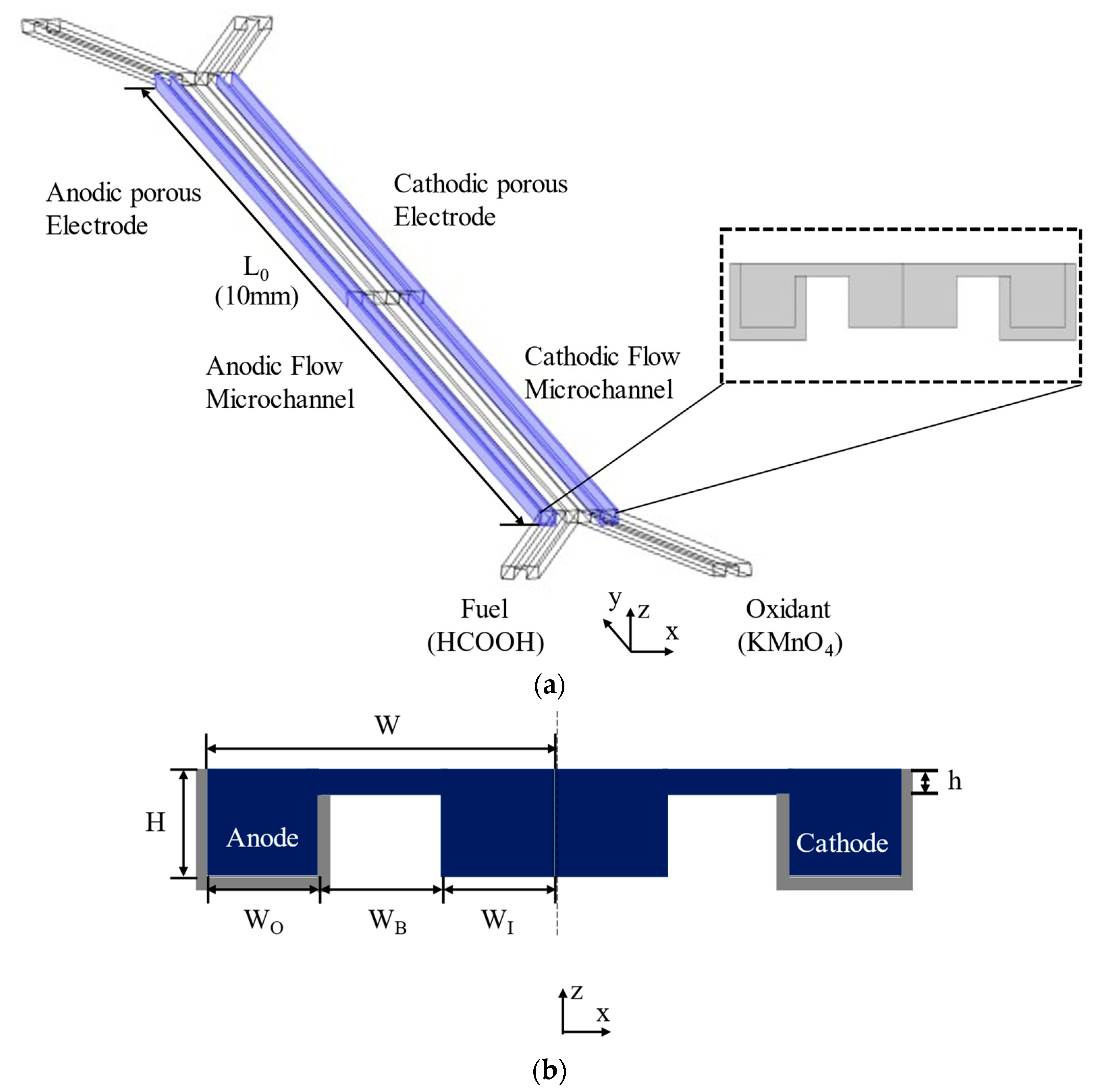
Figure 1 shows the configuration of the MMFC with a double-bridge shape flow channel cross-section. In Figure 1a, the fuel and oxidant enter through separate inlets and proceed along the microchannel, and the electrodes surround the outer channel. The proposed channel cross-section was modified from the single-bridge cross-section design of Montesinos et al. [17], shown in Figure 2. The single-bridge channel separates the mixing region on the bridge from the depletion regions on the electrodes to reduce crossover. The double-bridge cross-section, shown in Figure 1b, prevents the contraction of the mixing region from occurring in the single-bridge channel. The double-bridge channel provides more efficient proton transportation than the single-bridge channel by adding a bridge to the channel. The single-bridge structure reduces the height of the mixing region by locating it on the bridge, which poses greater resistance to the passage of ions. However, in the double-bridge cross-section, the mixing region is extended to the full height of the channel.
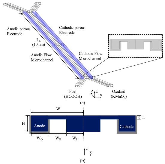
Figure 1.
Double-bridge shaped MMFC channel. (a) Flow channel and electrode locations, (b) channel cross-section (grey regions indicate electrodes).
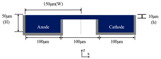
Figure 2.
Cross-section of the single-bridge channel proposed by Montesinos et al. [17] (grey regions indicate electrodes).
The channel half-width is W = 150 µm and the channel height is H = 50 µm (Figure 1b). The length of the microchannel is L0 = 10 mm (Figure 1a). The dimensions of the reference double-bridge cross-section are as follows: the bridge height is h = 10 µm and the outer channel width (WO), bridge width (WB), and inner channel width (WI) are equal to 50 µm. A parametric study of the double-bridge design was performed using the geometric parameters WO/Wr, WB/Wr, WI/Wr, and h/H, where Wr = 50 µm is the reference width. A flow rate of 60 µLmin−1 was used for the investigations.
3. Numerical Analysis
Due to the micro-scale dimensions and, thus, the low Reynolds number, the flow is laminar in the MMFC microchannel. To simplify the numerical model for the electrochemical phenomena in the MMFC, it was assumed that the flow is steady and Newtonian with constant fluid density, and the temperature is constant. It was also assumed that the depletion region does not largely affect the mixing region, even at the channel exit where the mixing region is the thickest. COMSOL Multiphysics® (version 4.3, COMSOL, Inc., Stockholm, Sweden) [38] was used for the numerical investigation.
The equations for mass and momentum conservations of the flow are written, respectively, as follows:
where ρ, p, u, and μ are the fluid density (= 1 × 10³ kg·m−3), pressure, velocity vector, and absolute viscosity (=1 × 10⁻³ Pa·s), respectively.
Numerous studies for MMFCs [4,20,39,40] have employed liquid reactants due to their high energy density and convenient storage. In the present work, potassium permanganate and formic acid were used as the oxidant and fuel, respectively.
The velocity field paves the path to find the reactant transportation in MMFCs. The reactants are transported downstream in the channel by convection. However, diffusive transportation replaces the consumed or depleted reactants in the vicinity of electrodes with fresh reactants. The following Fick’s law was employed to determine the reactant transportation in the MMFC [41].
where D is the diffusivity (= 5 × 10⁻¹⁰ m2 s−1) and c is the concentration of a species.
The concentration and velocity fields can be found with the above equations. A constant pressure condition was assigned to the exit of the channel, and a cell pressure drop () was assigned to the inlet (pin). No-slip conditions were assigned to the walls of the channel. A convection mass flux is used at the exit, and a constant concentration is used at the inlet. Transportation through the channel walls is ignored as follows:
Faraday’s law and the Butler–Volmer equations were employed to model the MMFC electrochemical reactions [42]. It was supposed that the ion (i.e., H+ or OH−) concentration is constant in the channel [28].
The mass transport equation was updated to use the electrode reactions. The transportation of the species in a channel is expressed as follows:
where n, Jn, ei, and F are the charge number used in the reactions, the current produced at the electrode, the number of moles, and the Faraday constant, respectively. Except for the reactive walls, Jn is zero. The reactants consumed on the electrodes were calculated by Faraday’s law.
The current transportation is described as follows:
and are the source terms for the layer’s conductivity (=3.5 S·m−1), local potential, the electrochemical surface area, and the current, respectively. Neglecting the volumetric terms, the equation can be written as
To consider the impact of the concentration gradient of the reactant species on the current, the original Butler–Volmer equations were multiplied by the concentration term. The modified Butler–Volmer equations describe as follows:
where , , and are the exchange current density (=0.46 A·m−2 for the anode and cathode), the charge transfer coefficient (= 0.5), and the overpotential, respectively. In addition, cref and T are the reference concentration and temperature (= 298 K), respectively.
The Navier–Stokes, convection-and-diffusion, and Butler–Vomer equations were coupled together and solved numerically to predict the current density for the specified cell voltage values. Each point on the polarization curve refers to the predicted current density at a specific cell voltage, that is, the solid phase cell voltage assigned to the cathode, whereas the cell voltage at the anode is zero, that is, arbitrarily chosen as the ground. Hence, the current density was numerically calculated by integrating the normal current density on the cathode boundaries and normalizing it to the electrode area or channel volume, which led to finding the geometry that produces the highest power density.
The overpotentials of the electrodes are as follows:
The potentials of the electrode (= Vcell) and the electrolyte were calculated from the potential equations. The reversible potential (, −0.7 for the anode and 1.33 V for the cathode) was a constant that was based on the reaction Gibbs free energy change at standard conditions [28].
This computational model introduced an assumption of single-phase flow and, hence, the formation of gas bubbles (e.g., CO2 and O2) was ignored. It was assumed that the bubbles formed at the anode were completely dissolved in the electrolyte. Although the single-phase assumption led toward a slight overestimation of the cell performance, most of the simulations reported to date on MMFCs introduced a single-phase assumption [17,18,23,26,27,29]. Nevertheless, Shyu et al. [43] and Wang et al. [44] investigated two-phase numerical models to capture the effects of bubble formation on MMFC performance.
4. Results and Discussion
In this study, grid convergence index (GCI) analysis, characterized by Richardson extrapolation [45], was performed to assess the grid dependence of the numerical results. The GCI analysis results for the MMFC output current at a cell voltage of 0.6 V are summarized in Table 1. As the number of grid nodes increased, the current of the MMFC tended to converge gradually, as shown in Figure 3. When N1 was used, the extrapolated relative error was 0.131% and the GCI was 0.163%. Therefore, N1 was finally selected for the grid system, and further calculations were conducted based on this grid structure. Tetrahedral meshes were generated in the specified computational domain. The meshes were created in COMSOL using an inbuilt physics-controlled mesh option. The meshes created at the boundary layers were comprised of fine elements.

Table 1.
Grid convergence index (GCI) analysis for the MMFC current.
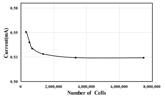
Figure 3.
Grid-dependency test.
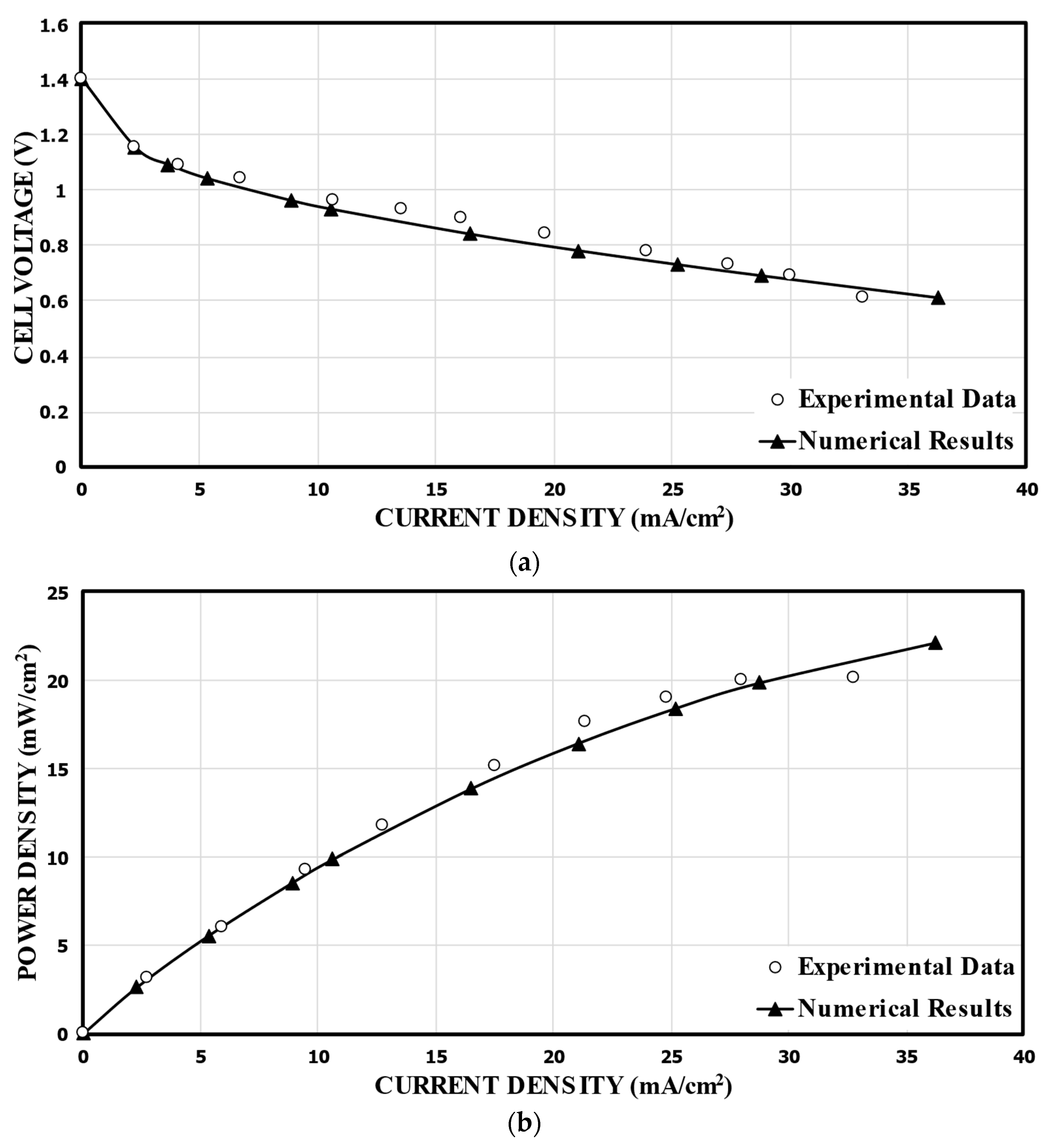
In order to validate the numerical results, the predicted performance curves for the single-bridge channel (Figure 2) were compared with the corresponding experimental measurements [17], as shown in Figure 4. For the calculation, 1000 mol/m3 of HCOOH and 144 mol/m3 of KMnO4 were used. Compared to the experimental data, the numerical results show the highest relative error of 19.0% at a cell voltage of 0.9 V, and the lowest relative error of 0.65% at 0.7 V. Good overall agreements are shown in the comparisons. Figure 4b presents the power density versus the current density curve. The power density of the MMFC was determined by multiplying the current density by the cell voltage. The predicted numerical results diverge somewhat from the previously reported experimental results at lower cell voltages. Nonetheless, essentially, the fuel cells functioned at a nominal cell voltage, that is, at a range of 0.6–0.8 V, and the numerical model results match with the experimental results remarkably well.
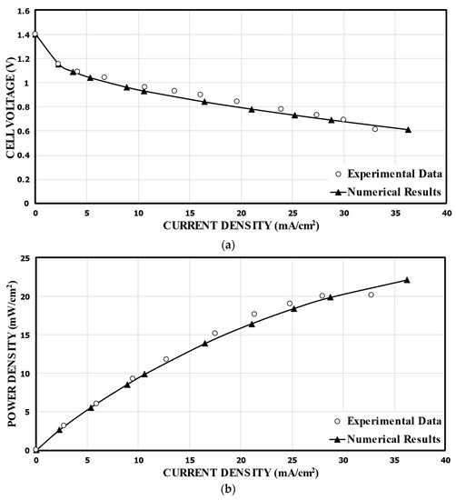
Figure 4.
Validation of the predicted performance curves using experimental data of Montesinos et al. [17]. (a).Cell voltage; (b). Power density.
Since the reactant species (i.e., the fuel and oxidant couple), electrode material, and the concentration of fuel/oxidant adopted for the proposed MMFC are similar to those of the MMFC with the reference bridge structure [17], the diffusivity of the reactant species, the number of electrons transferred during the reaction, the exchange current densities, the charge transfer coefficient, the reversible potential of the fuel/oxidant (versus the standard hydrogen electrode), and the conductivity are unchanged. This implies that the reaction kinetics, the voltage distribution within the solid-phase metallic electrodes, and the distribution of hydrogen ions are the same in both structures. However, reactant transportation, the transport of charged species, and the concentration gradients vary with the adaptation of different cross-sectional geometries.
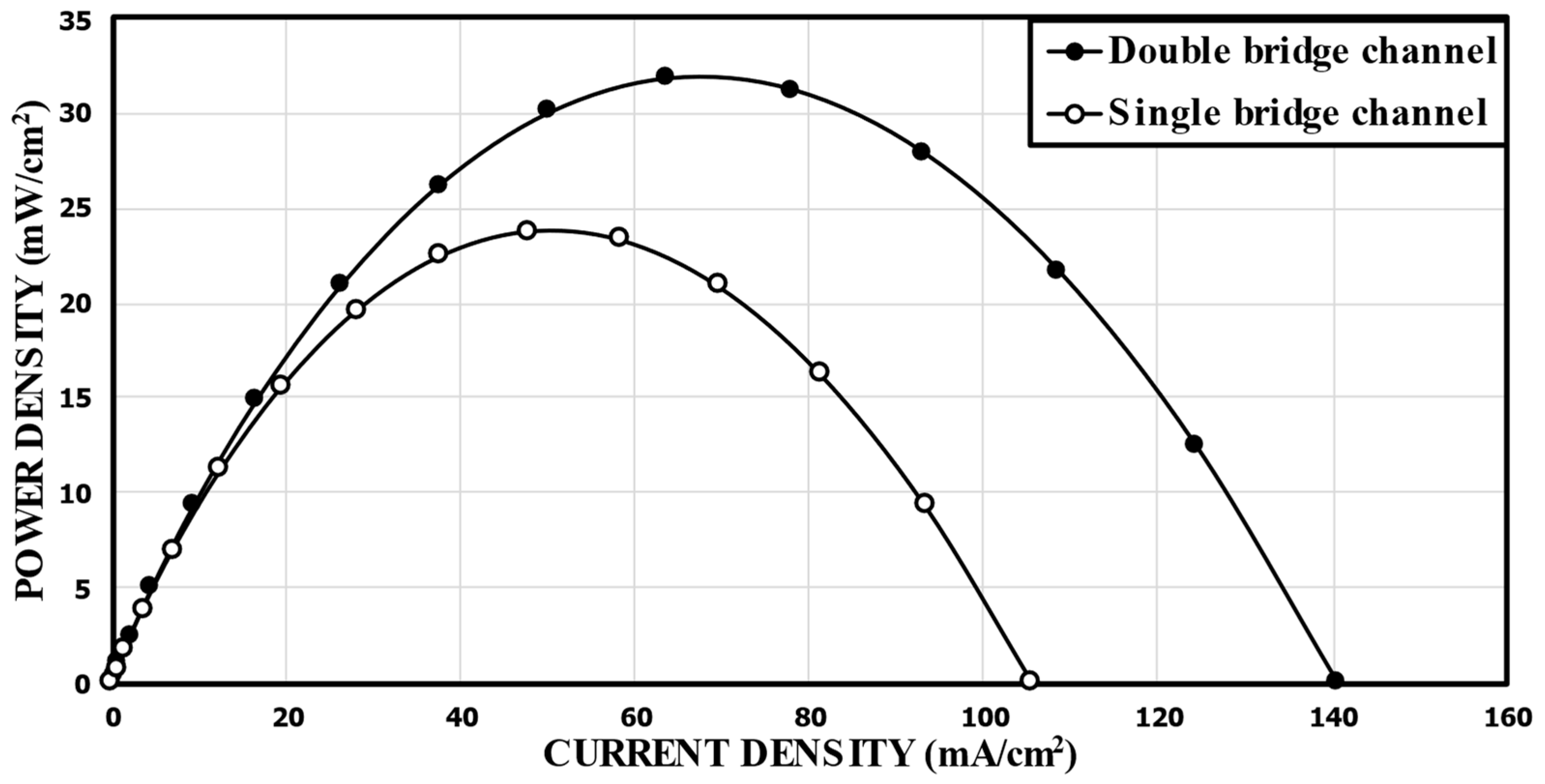
First, the performance of the MMFC with the double-bridge channel proposed in this work was compared with the single-bridge channel design of Montesinos et al. [17]. Figure 5 shows the comparison of the predicted power density curves between the reference double-bridge channel (Figure 1b) and the single-bridge channel (Figure 2). The peak power densities of the single-bridge and double-bridge channels were 23.79 mW/cm2 and 31.88 mW/cm2, respectively. This means that the reference double-bridge channel showed a 34.0% higher peak power density than that of the single-bridge channel proposed by Montesinos et al. [17].

Figure 5.
Comparison of predicted performance curves between the single-bridge channel proposed by Montesinos et al. [17] and the reference double-bridge channel.
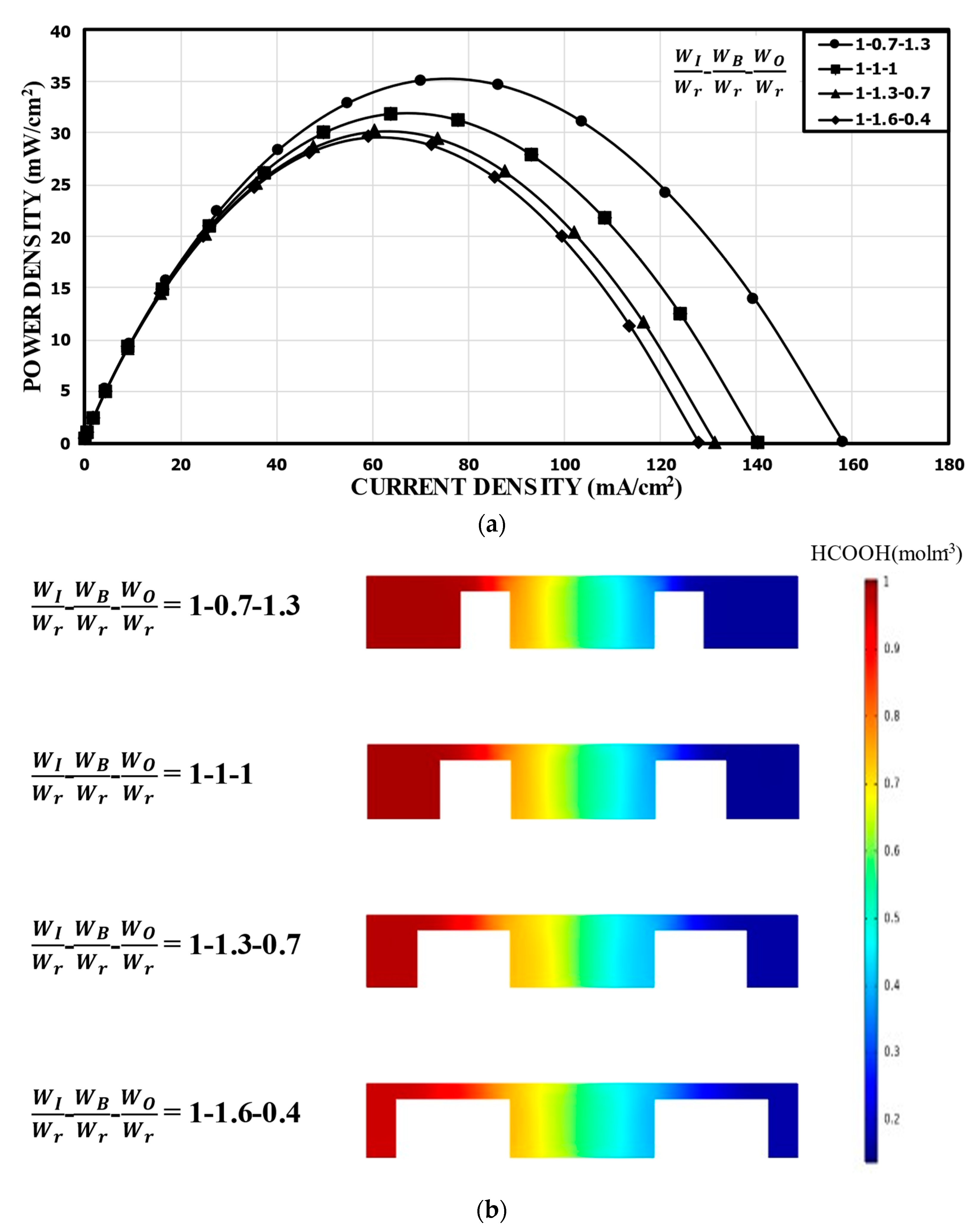
The overall channel width (2 W) is fixed in the double-bridge channel, and WI, WB, and WO are related by WB = W − WI − WO. For a fixed width of the inner channel of WI/Wr 1.0, the power density curves for different WO/Wr (or WB/Wr) are shown in Figure 6a. In this case, the variation of the performance was not large. Compared to the reference channel with the same sub-widths (31.88 mW/cm2), WB/Wr = 0.7 (WO/Wr = 1.3) showed about a 10.0% higher peak power density (35.11 mW/cm2), while WB/Wr = 1.6 (WO/Wr = 0.4) showed about a 7.0% lower peak power density (29.65 mW/cm2). This indicates that as the width of the narrow channel (WB) increased, the resistance to the movement of the ions increased, which caused the performance of the MMFC to deteriorate slightly. Figure 6b shows the concentration distributions of the fuel (HCOOH) in the xz plane located at 5 mm from the channel inlet. Although the thickness of the mixing region did not show any significant change, ohmic losses were affected by the width of the narrow channel and the flow area around the electrode in the outer channel.

Figure 6.
Power density curves for fixed WI: (a) performance curves; (b) concentration contours of fuel (HCOOH) at the xz plane, 5 mm from the channel inlet.
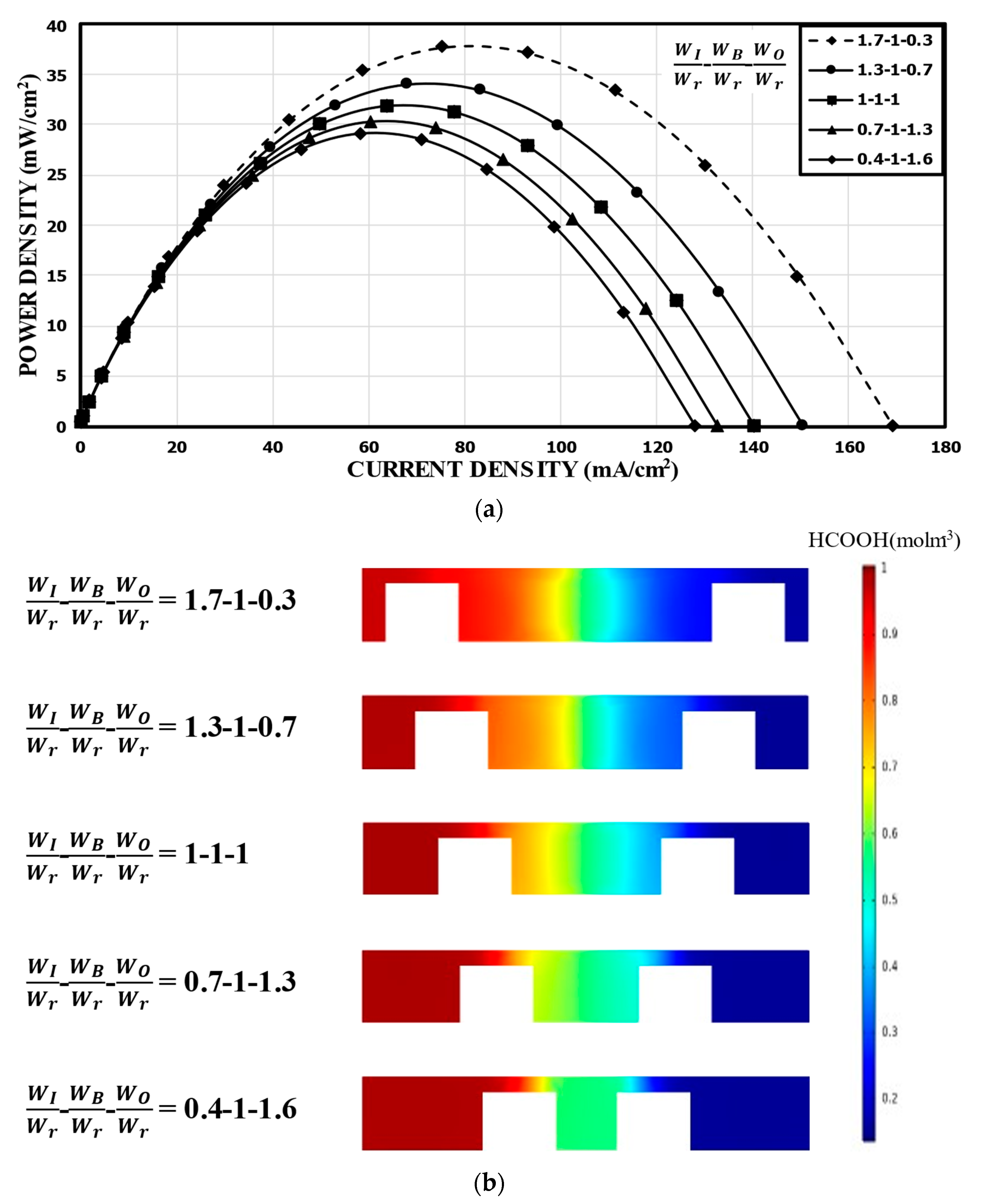
Figure 7 shows the results for when WB was fixed at WB/Wr = 1.0. Compared to the reference channel, WI/Wr = 1.7 (WO/Wr = 0.3) showed a peak power density (37.75 mW/cm2) increased by about 18%, while WI/Wr = 0.4 (WO/Wr = 1.6) showed about an 8% lower peak power density (29.16 mW/cm2) in Figure 7a. Thus, the power density increased as WI/Wr increased (i.e., WO/Wr decreases). Observing the concentration contours in Figure 7b, it is noticeable that, as WI reduced, the thickness of the mixing region increased, which tended to increase the ohmic losses. The mixing region extended evenly to the channel over the bridge structure for WI/Wr = 0.4 and 0.7. Although an increase in WO ensured the accommodation of the reactants in the anodic or cathodic half channel, the thickened mixing region reduced the overall performance of the MMFC. This indicates that WI was quite sensitive to the performance of the MMFC with the double-bridge structure.
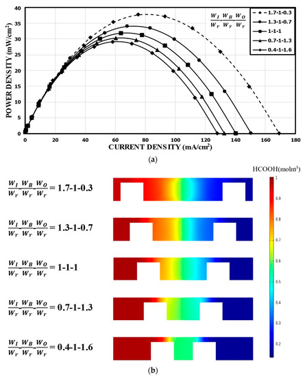
Figure 7.
Power density curves for fixed WB: (a) performance curves; (b) concentration contours of fuel (HCOOH) at the xz plane, 5 mm from the channel inlet.
Figure 8 shows the results for a fixed bridge width at WO/Wr = 1.0. At WB/Wr = 0.7 (WI/Wr = 1.3), the peak power density was 36.79 mW/cm2, which is about 15% higher than that of the reference channel. However, WB/Wr = 1.6 (WI/Wr = 0.4) reduced the power density to 25.48 mW/cm2 by about 20% compared to the reference channel. Compared to the case with varying WO (Figure 7a), this case, with a fixed WO, showed the peak power density doubled in the range of WI/Wr = 0.4–1.3. As WI increased with the fixed WO, the positive effect of reducing the mixing region was similar to the previous case with varying WO, as shown in Figure 8b, but the negative effects of varying WO (i.e., reducing the area around the electrode in the outer channel and increasing the distance between the electrodes) was removed compared to the previous case (Figure 8). A smaller distance between the electrodes reduced the ohmic losses, and a larger space around each electrode accommodated more fresh reactants, which could be utilized effectively down the channel.
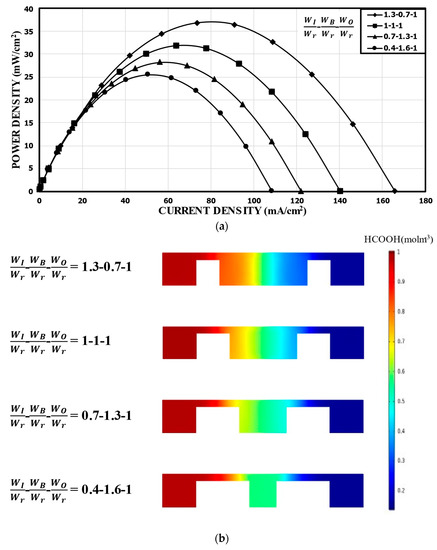
Figure 8.
Power density curves for fixed WO: (a) performance curves; (b) concentration contours of fuel (HCOOH) at the xz plane, 5 mm from the channel inlet.
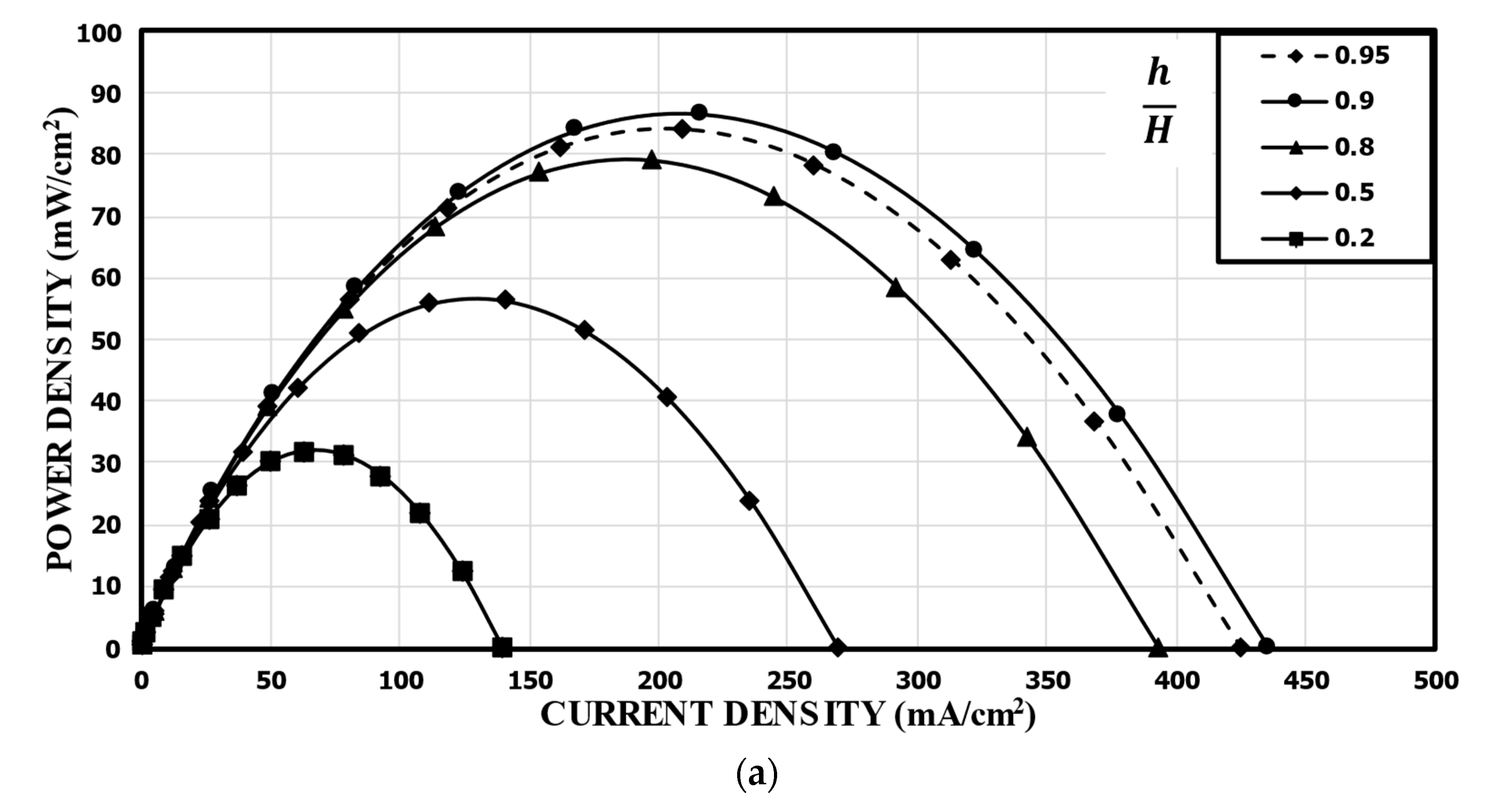
Tanveer and Kim et al. [37] studied the influence of the bridge height on the performance of an MMFC with the single-bridge channel. They found that as the bridge height (h) increased to a critical value, the power density increased. Figure 9 shows the variation of the power density curve of the reference double-bridge channel with the bridge height. As shown in Figure 9a, the power density was greatly sensitive to the bridge height, and as the bridge height increased, the peak power density increased but reached a maximum value at h/H = 0.9. The peak power density at h/H = 0.9 was 86.56 mw/cm2, which is about 171% higher than that at h/H = 0.2 (reference). This is because, as the height of the bridge increased, more ions passed through the diffusive mixing region, resulting in lower ohmic losses. It is found from the concentration contours of fuel shown in Figure 9b that, as h increased, the thickness of the mixing region was reduced, and the reduction rate was higher for smaller h/H. Increasing h/H beyond 0.9 reduced the performance because the reactants could not transport toward the active sites effectively, as in a multi-faceted electrode structure. As the channel cross-section adopted the rectangular shape (h/H = 1), the performance of the MMFC was reduced abruptly. When the multi-faceted electrode structure vanished, the reactant mass transportation was reduced abruptly and, hence, the performance of the MMFC decreased.

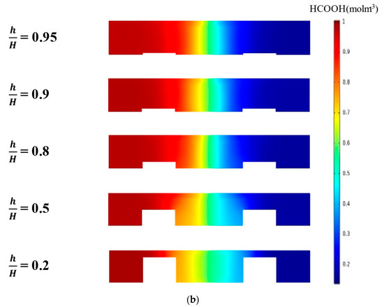
Figure 9.
Effect of bridge height on the power density curve: (a) performance curves; (b) concentration contours of fuel (HCOOH) at the xz plane, 5 mm from the channel inlet.
The bridge structure allows for housing a multi-faceted electrode structure and isolates the mixing region from the depletion region, which improves the reactants’ mass transportation. The bridge structure ensures that the fresh reactants dip toward the depleted reactants, and it enhances the reactants’ transportation. The single-bridge structure was investigated by Montesinos et al. [17] initially, and they found that reducing the bridge height increased the ohmic losses, which reduced the performance as well. Thus, the narrow-bridge structure imparts higher resistance to the passage of ions and increases ohmic losses. On the other hand, the double-bridge structure does not manipulate the mixing region while changing the bridge height, and hence, the ohmic loss does not increase significantly with a reduction in bridge height.
5. Conclusions
In this study, we investigated a double-bridge-shaped cross-section of an MMFC flow channel. Using a numerical model, the operations occurring inside an MMFC, such as mass transportation, reaction kinetic, and electrochemical phenomena, were coupled and simulated. The numerical results were validated with previously reported experimental data. From the results, the following conclusions were obtained:
- (1)
- In comparison to the single-bridge channel, the reference double-bridge channel with equal sub-channel widths showed a 34.0% higher peak power density (31.88 mW/cm2), which demonstrates the superiority of the proposed MMFC flow channel shape.
- (2)
- The effects of the sub-channel widths (WI, WB, and WO) with the fixed total channel width and the bridge height (h) of the double-bridge channel on the performance were further investigated. Among the sub-channel widths, the width of the inner channel (WI) was found to be the most influential on the power density of the MMFC. Thus, the case with a fixed WI showed the least variation of the power density.
- (3)
- In the case with fixed WB or fixed WO, the power density increased with WI. The main reason was proved to be the reduced thickness of the mixing region in the inner channel with the increased WI. In the case with fixed WB/Wr = 1.0, WI/Wr = 1.7 (WO/Wr = 0.3) showed about an 18% higher peak power density compared to the reference channel. However, compared to this case, with varying WO, the case with fixed WO/Wr = 1.0 showed more than double a larger variation in the peak power density in the range of WI/Wr = 0.4–1.3. This is because the negative effects of varying WO, such as reducing the area around the electrode in the outer channel and increasing the distance between the electrodes, were removed in this case. WB/Wr = 0.7 (WI/Wr = 1.3) showed about a 15% higher peak power density than that of the reference channel.
- (4)
- The height of the double-bridge structure had the greatest effect on performance, as expected. As h/H increased, the peak power density reached a maximum at h/H = 0.9, which was 171% higher than that of the reference channel (h/H = 0.2). The concentration contours of fuel showed that the thickness of the mixing region reduced as h increased, and the reduction rate was higher for smaller h/H.
Author Contributions
J.-H.O.: numerical analysis, writing—original draft, M.T.: conceptualization, investigation, writing—original draft, K.-Y.K.: writing—review and editing, supervision, funding acquisition. All authors have read and agreed to the published version of the manuscript.
Funding
This work was supported by the National Research Foundation of Korea (NRF) grant funded by the Korean government (MSIT) (No. 2019R1A2C1007657).
Institutional Review Board Statement
Not applicable.
Informed Consent Statement
Not applicable.
Data Availability Statement
Not applicable.
Conflicts of Interest
The authors declare no conflict of interest.
Nomenclature
| Surface area (m2) | Greek symbols | ||
| Species concentration (mol) | Charge transfer coefficient | ||
| Diffusivity (m2/s) | Overpotential (V) | ||
| Number of moles | Fluid viscosity (Pa s) | ||
| Faraday constant (C/mol) | Fluid density (kg/m3) | ||
| Bridge height (µm) | Conductivity (S/m) | ||
| Exchange current density (A/m) | Local potential (V) | ||
| Current | Liquid-phase local potential (V) | ||
| Current normal to the surface | Reversible potential (V) | ||
| Length of microchannel (mm) | Solid-phase local potential (V) | ||
| Unit normal vector | |||
| Pressure (Pa) | |||
| Gas constant (J/mol K) | |||
| Source term | |||
| Temperature (K) | |||
| Velocity vector (m/s) | |||
| Channel half-width (µm) | |||
| Bridge channel width (µm) | |||
| Inner channel width (µm) | |||
| Outer channel width (µm) | |||
| Reference width (µm) | |||
References
- Kamarudin, S.K.; Daud, W.R.W.; Som, A.M.; Takriff, M.S.; Mohammad, A.W.; Loke, Y.K. Design of a fuel processor unit for PEM fuel cell via shortcut design method. Chem. Eng. J. 2014, 104, 7–17. [Google Scholar] [CrossRef]
- Achmad, F.; Kamarudin, S.K.; Daud, W.R.W.; Majlan, E.H. Passive direct methanol fuel cells for portable electronic devices. Applied Energy 2011, 88, 1681–1689. [Google Scholar] [CrossRef]
- Dyer, C.K. Fuel cells for portable applications. J. Power Sources 2002, 106, 31–34. [Google Scholar] [CrossRef]
- Kjeang, E.; Djilali, N.; Sinton, D. Microfluidic fuel cells: A review. J. Power Sources 2009, 186, 353–369. [Google Scholar] [CrossRef]
- Lee, S.J.; Chang-Chien, A.; Cha, S.W.; O’Hayre, R.; Park, Y.I.; Saito, Y.; Prinz, F.B. Design and fabrication of a micro fuel cell array with ‘‘flip-flop’’ interconnection. J. Power Sources 2002, 112, 410–418. [Google Scholar] [CrossRef]
- Motokawa, S.; Mohamedi, M.; Momma, T.; Shoji, S.; Osaka, T. MEMS-based design and fabrication of a new concept micro direct methanol fuel cell (l-DMFC). Electrochem. Commun. 2004, 6, 562–565. [Google Scholar] [CrossRef]
- Pan, Z.F.; An, L.; Zhao, T.S.; Tang, Z.K. Advances and challenges in alkaline anion exchange membrane fuel cells. Prog. Energy Combust. Sci. 2018, 66, 141–175. [Google Scholar] [CrossRef]
- Pan, Z.F.; Chen, R.; An, L.; Li, Y.S. Alkaline anion exchange membrane fuel cells for cogeneration of electricity and valuable chemicals. J. Power Sources 2017, 365, 430–445. [Google Scholar] [CrossRef]
- An, L.; Chen, R. Direct formate fuel cells: A review. J. Power Sources 2016, 320, 127–139. [Google Scholar] [CrossRef]
- Xiao, Z.Y.; Feng, C.H.; Chan, P.C.H.; Hsing, I.M. Monolithically integrated planar microfuel cell arrays. Sens. Actuators B 2008, 132, 576–586. [Google Scholar] [CrossRef]
- Yeom, J.; Mozsgai, G.Z.; Flachsbart, B.R.; Choban, E.R.; Asthana, A.; Shannon, M.A.; Kenis, P.J.A. Microfabrication and characterization of a silicon-based millimeter scale, PEM fuel cell operating with hydrogen, methanol, or formic acid. Sens. Actuators B 2005, 107, 882–891. [Google Scholar] [CrossRef]
- Yu, J.G.; Cheng, P.; Ma, Z.Q.; Yi, B.L. Fabrication of a miniature twin-fuel-cell on silicon wafer. Electrochim. Acta 2003, 48, 1537–1541. [Google Scholar] [CrossRef]
- Patil, A.; Dubois, T.G.; Sifer, N.; Bostic, E.; Gardner, K.; Quah, M.; Bolton, C. Portable fuel cell systems for America’s army: Technology transition to the field. J. Power Sources 2004, 136, 220–225. [Google Scholar] [CrossRef]
- Frank, M.; Erdler, G.; Freichs, H.P.; Muller, C.; Reinecke, H. Chip integrated fuel cell accumulator. J. Power Sources 2008, 181, 371–377. [Google Scholar] [CrossRef]
- Moore, C.W.; Li, J.; Kohl, P.A. Microfabricated Fuel Cells with Thin-Film Silicon Dioxide Proton Exchange Membranes. J. Electrochem. Soc. 2005, 152, A1606–A1612. [Google Scholar] [CrossRef]
- Choban, E.R.; Spendelow, J.S.; Gancs, L.; Wieckowski, A.; Kenis, P.J.A. Membraneless c-based micro fuel cells operating in alkaline, acidic, and acidic/alkaline media. Electrochim. Acta 2005, 50, 5390–5398. [Google Scholar] [CrossRef]
- López-Montesinos, P.O.; Yossakda, N.; Schmidt, A.; Brushett, F.R.; Pelton, W.E.; Kenis, P.J.A. Design, fabrication, and characterization of a planar, silicon-based, monolithically integrated micro laminar flow fuel cell with a bridge-shaped microchannel cross-section. J. Power Sources 2001, 196, 4638–4645. [Google Scholar] [CrossRef]
- Tanveer, M.; Kim, K.Y. Effects of geometric configuration of the channel and electrodes on the performance of a membraneless micro-fuel cell. Energy Convers. Manag. 2017, 136, 372–381. [Google Scholar] [CrossRef]
- Hollinger, A.S.; Maloney, R.J.; Jayashree, R.S.; Natarajan, D.; Markoski, L.J.; Kenis, P.J.A. Nanoporous separator and low fuel concentration to minimize crossover in direct methanol laminar flow fuel cells. J. Power Sources 2010, 195, 3523–3528. [Google Scholar] [CrossRef]
- Choban, E.R.; Markoski, L.J.; Wieckowski, A.; Kenis, P.J.A. Microfluidic fuel cell based on laminar flow. J. Power Sources 2004, 128, 54–60. [Google Scholar] [CrossRef]
- Sprague, I.B.; Byun, D.Y.; Dutta, P. Effects of reactant crossover and electrode dimensions on the performance of a microfluidic based laminar flow fuel cell. Electrochim. Acta 2010, 55, 8579–8589. [Google Scholar] [CrossRef]
- Jayashree, R.S.; Gancs, L.; Choban, E.R.; Primak, A.; Natarajan, D.; Markoski, L.; Kenis, P.J.A. Air-Breathing Laminar Flow-Based Microfluidic Fuel Cell. J. Am. Chem Soc 2005, 127, 16758–16759. [Google Scholar] [CrossRef]
- Shaegh, S.A.M.; Nguyen, N.T.; Chan, S.H. An air-breathing microfluidic formic acid fuel cell with a porous planar anode: Experimental and numerical investigations. J. Micromech. Microeng. 2010, 20, 105008. [Google Scholar] [CrossRef] [Green Version]
- Sun, M.H.; Casquillas, G.V.; Guo, S.S.; Shi, J.; Ji, H.; Ouyang, Q.; Chen, Y. Characterization of microfluidic fuel cell based on multiple laminar flow. Microelectron. Eng. 2007, 84, 1182–1185. [Google Scholar] [CrossRef]
- Chang, M.H.; Chen, F.; Fang, N.S. Analysis of membraneless fuel cell using laminar flow in a Y-shaped microchannel. J. Power Sources 2006, 159, 810–816. [Google Scholar] [CrossRef]
- Ahmed, D.H.; Park, H.B.; Sung, H.J. Optimum geometrical design for improved fuel utilization in membraneless micro fuel cell. J. Power Sources 2008, 185, 143–152. [Google Scholar] [CrossRef]
- Bazylak, A.; Sinton, D.; Djilali, N. Improved fuel utilization in microfluidic fuel cells: A computational study. J. Power Sources 2005, 143, 57–66. [Google Scholar] [CrossRef]
- Khabbazi, A.E.; Richards, A.J.; Hoorfar, M. Numerical study of the effect of the channel and electrode geometry on the performance of microfluidic fuel cells. J. Power Sources 2010, 195, 8141–8151. [Google Scholar] [CrossRef]
- Krishnamurthy, D.; Johansson, E.O.; Lee, J.W.; Kjeang, E. Computational modeling of microfluidic fuel cells with flow-through porous electrodes. J. Power Sources 2011, 196, 10019–10031. [Google Scholar] [CrossRef]
- Wang, H.; Leung, D.Y.C.; Xuan, J. Modeling of an air cathode for microfluidic fuel cells: Transport and polarization behaviors. Int. J. Hydrogen Energy 2011, 36, 14704–14718. [Google Scholar] [CrossRef]
- Xuan, J.; Leung, D.Y.C.; Leung, M.K.H.; Wang, H.; Ni, M. Chaotic flow-based fuel cell built on counter-flow microfluidic network: Predicting the over-limiting current behavior. J. Power Sources 2011, 196, 9391–9397. [Google Scholar] [CrossRef]
- Xuan, J.; Leung, D.Y.C.; Leung, M.K.H.; Wang, B.; Ni, M. Air-breathing membraneless laminar flow-based fuel cells: Do they breathe enough oxygen? Appl. Energy 2013, 104, 400–407. [Google Scholar] [CrossRef]
- Thorson, M.R.; Brushett, F.R.; Timberg, C.J.; Kenis, P.J.A. Design rules for electrode arrangement in an air-breathing alkaline direct methanol laminar flow fuel cell. J. Power Sources 2012, 218, 28–33. [Google Scholar] [CrossRef]
- Brushett, F.R.; Naughton, M.S.; Ng, J.W.D.; Yin, L.; Kenis, P.J.A. Analysis of Pt/C electrode performance in a flowingelectrolyte alkaline fuel cell. Int. J. Hydrogen Energy 2012, 37, 2559–2570. [Google Scholar] [CrossRef]
- Tanveer, M.; Kim, K.Y. Performance analysis of microfluidic fuel cells with various inlet locations and multiple compartments. Energy Convers. Manag. 2018, 166, 328–336. [Google Scholar] [CrossRef]
- Tanveer, M.; Kim, K.Y. Performance analysis of a micro laminar flow fuel cell with multiple inlets of a bridge-shaped microchannel. J. Power Sources 2018, 399, 8–17. [Google Scholar] [CrossRef]
- Tanveer, M.; Kim, K.Y. Effects of Bridge-Shaped Microchannel Geometry on the Performance of a Micro Laminar Flow Fuel Cell. Micromachines 2019, 10, 822. [Google Scholar] [CrossRef] [Green Version]
- COMSOL AB. COMSOL Multiphysics Reference Guide; (Version 4.3); COMSOL, Inc.: Stockholm, Sweden, 2012; Available online: www.comsol.com (accessed on 26 November 2019).
- Shaegh, S.A.M.; Nguyen, N.T.; Chan, S.H. A review on membraneless laminar flow-based fuel cells. Int. J. Hydrogen Energy 2011, 36, 5675–5694. [Google Scholar] [CrossRef] [Green Version]
- Tanveer, M.; Lim, E.S.; Kim, K.Y. Effects of channel geometry and electrode architecture on reactant transportation in membraneless microfluidic fuel cells: A review. Fuel 2021, 298, 120818. [Google Scholar] [CrossRef]
- Bird, R.B. Transport phenomena. Appl. Mech. Rev. 2002, 55, R1–R4. [Google Scholar] [CrossRef]
- Ni, M.; Leung, M.K.H.; Leung, D.Y.C. Parametric study of solid oxide fuel cell performance. Energy Convers. Manag. 2007, 48, 1525–1535. [Google Scholar] [CrossRef]
- Shyu, J.C.; Wei, C.S.; Lee, C.J.; Wang, C.C. Investigation of bubble effect in microfluidic fuel cells by a simplified microfluidic reactor. Appl. Therm. Eng. 2010, 30, 1863–1871. [Google Scholar] [CrossRef]
- Wang, H.N.; Zhu, X.; Zhang, B.; Ye, D.D.; Chen, R.; Liao, Q.; Sui, P.C.; Djilali, N. Two-phase computational modelling of a membraneless microfluidic fuel cell with a flow-through porous anode. J. Power Sources 2019, 420, 88–98. [Google Scholar] [CrossRef]
- Roache, P.J. Verification of Codes and Calculations. AIAA J. 1998, 36, 696–702. [Google Scholar] [CrossRef]


Publisher’s Note: MDPI stays neutral with regard to jurisdictional claims in published maps and institutional affiliations. |
© 2021 by the authors. Licensee MDPI, Basel, Switzerland. This article is an open access article distributed under the terms and conditions of the Creative Commons Attribution (CC BY) license (https://creativecommons.org/licenses/by/4.0/).