1. Introduction
About 50% of Europe’s total energy consumption is channeled for heating and cooling, much of it being inefficiently used [
1]. Over 35% of the overall energy consumption is directed to the building sector, from which 75% is used for space and domestic water heating [
2]. Nowadays, much of this energy is still being wasted through inefficient processes and heat losses. In addition, only 18% of the total energy used for heating and cooling comes from renewables, 75% coming from fossil fuels burning and 7% from nuclear power plants [
1]. Furthermore, the residential sector accounts for 17% of global CO
2 emissions [
3]. Efforts must be made to increase the share of renewables for heating and cooling, contributing towards a sustainable and greener future. Considering the intermittent nature of renewable energy sources, energy storage technologies can improve the effectiveness of the use of renewables [
4]. Adsorption heat pumps (AHPs) can play a significant role towards the achievement of a green world. Unlike conventional vapor compression heat pumps (VCHPs) that use high global warming potential (GWP) fluids, AHPs can work with natural refrigerants like water or ammonia. Furthermore, contrary to the VCHPs, which are electrically driven, AHPs may be driven directly by thermal energy such as waste or surplus heat [
5,
6], renewable energy sources like solar energy [
7,
8,
9], or even with heat from natural gas [
10].
By 2016, combustible fuels (coal, oil, natural gas, biofuels, industrial and municipal waste, etc.) represented 67.3% of the total electricity production worldwide. Pressurized steam, generated from combustion heat, is used to drive an electric generator by spinning a steam turbine. Most power plants worldwide still use this system to produce electricity. A large amount of energy is wasted since only a fraction of the heat generated by burning the fuels is converted into electricity [
11]. This must be considered when comparing the coefficient of performance (COP) of AHPs and VCHPs. The significantly lower COP of AHPs is usually interpreted as a major disadvantage. However, for VCHPs the COP is obtained as the ratio between the thermal energy output (useful effect) and the electrical energy input required to drive the system. Thus, for comparison purposes, the fraction of energy that is lost in the above referred to electricity generation process should also be considered as an energy consumption for VCHPs, for a fair comparison between these two technologies. Therefore, when this energy loss is accounted for, the COP of conventional VCHPs is significantly lower than what is commonly presented. Taking this into account, the lower COP of AHPs is not as low as how it is usually compared with that of the VCHPs, and it should not be seen to be such a big disadvantage. There are systems being developed that are addressing this handicap of VCHPs by using photovoltaic panels, but the compressors are always electricity dependent [
12,
13].
Several advancements in AHP technologies have recently been reported. Gluesenkamp et al. carried out an experimental study on the thermal mass of adsorption heat exchangers with several designs [
14]. A combination of compression units with adsorption-based systems is being considered, which aims to achieve a system that can integrate the best of each technology [
15]. Different control methods for AHPs have been recently investigated through two different approaches [
16]. One of the methods is to control the system based on the refrigerant concentration in the adsorbent bed. The second method is to consider the adsorbent bed temperature as the control variable. For source temperatures lower than the design value, a 5–50% improvement in the overall COP is reported. Pan et al. investigated a cascaded cycle which integrates four adsorbers [
17]. This cycle resulted in an improved COP by increasing the refrigerant quantity that is adsorbed within each cycle. The performance improvements are more notorious for low heat source temperature, high heat sink temperature, and high evaporation temperature working conditions. Adsorption systems based on cascaded cycles are also being used for cooling applications [
18]. Furthermore, adsorption systems are being tested not only for heating and cooling, but also for desalination purposes [
19].
The interest in the implementation of adsorption systems as energy storage devices has been increasing over the last 5 years [
20]. Adsorption systems can store heat in several forms. The adsorbent material can be regenerated when a heat source is available, keeping a potential to the release heat of adsorption when required, simply by opening a valve. The latent heat captured in the evaporator from a free energy source during the adsorption phase can also be released in the condenser during regeneration. Furthermore, sensible heat is stored as hot water inside an isolated reservoir.
This paper presents the analysis of a coated tube adsorber for AHPs suitable for space and water heating, and heat storage applications. The dependence of the system from various governing parameters like the evaporator’s and condenser’s temperature, cycle time, metal–adsorbent heat transfer coefficient, regeneration temperature metal tube diameter, coating thickness and heat transfer fluid (HTF) velocity on the adsorber’s performance is investigated and discussed for two sets of working conditions. The working conditions for Scenario A are suitable for pre-heating water in mild climates, whereas those for Scenario B are based on the European standard EN16147. Understanding the dynamics of these systems will lead to better control strategies as well as effective integration with renewable energy sources.
Improving the overall performance of AHP systems requires detailed numerical models capable of identifying the optimal values for the several governing parameters, configurations, and designs. Computational power has been increasing, allowing the implementation of numerical models with a higher detail level, both in the parameters considered, the space dimensions and resolution along each dimension, and the time resolution, leading to improved accuracy. This paper makes use of a physical model that has been proven to be highly accurate implemented on a coated tube adsorber for AHP to investigate the effect of the several governing parameters on the adsorber performance. This high level of detail if often used for materials studies, only accounting for small amounts of adsorbent. The use of detailed models on real scale applications is of major importance towards the achievement of improved and market-ready AHP.
The research for new adsorbent materials with enhanced characteristics and new adsorber designs are important for further advancements in AHP technology and have recently been the focus of several studies [
21,
22,
23]. On the other hand, system-level studies involving models that deal with all the components of an AHP system are lacking in the literature [
24]. Moreover, experimental studies reporting the properties and parameters with sufficient detail to allow the experimental validation of detailed models by other researchers for real scale applications cannot be found in the literature. Development of compact, affordable, and sustainable AHP systems is extremely important to increase the relevance of AHPs in the market. Therefore, a complete AHP system suitable for domestic water heating is proposed, which is a step forward in the literature related with adsorption heat pumps, usually dealing with some isolated components of the AHPs.
2. Adsorber Design
Several adsorber configurations and adsorbent packing techniques can be found in the literature, namely shell packing [
1], plate-finned, tube, finned tube, fin plate, flat pipe, spiral plate and a coated tube [
25]. The adsorber configuration that promises the best performance for AHPs is the coated tube setup due to the improved adsorbent-metal tube wall heat transfer and the higher thermal conductivity of adsorbent coatings [
26]. The major advantages of the coated tube configuration is the high adsorbent-metal heat transfer coefficient, the high adsorbent-metal surface area, and the compact size of the resulting construction, which results in higher heat exchanges between the HTF and the adsorbent material. Furthermore, it allows the inclusion of a greater adsorbent mass in a smaller volume, giving a higher energy storage density to the system. Therefore, the coated tube adsorber is the subject of this performance analysis.
As other adsorption applications, silica gel has been selected as an adsorbent material and water as an adsorbate [
27]. Given its availability, ease of handling and environmental friendship, the usage of water as an adsorbate is straightforward. On the other hand, silica gel was chosen based on its low regeneration temperature (60–100 °C), market availability and relatively low cost. The use of an adsorbent material that could be regenerated at temperatures under 95 °C is mandatory since water is also used as HTF, limiting the regeneration temperature to guarantee that the HTF remains in its liquid state. Furthermore, silica gel has a significant water adsorption capacity under space and domestic water heating working conditions, and information on its thermophysical properties and adsorption kinetics is already available from the open literature [
28,
29,
30,
31].
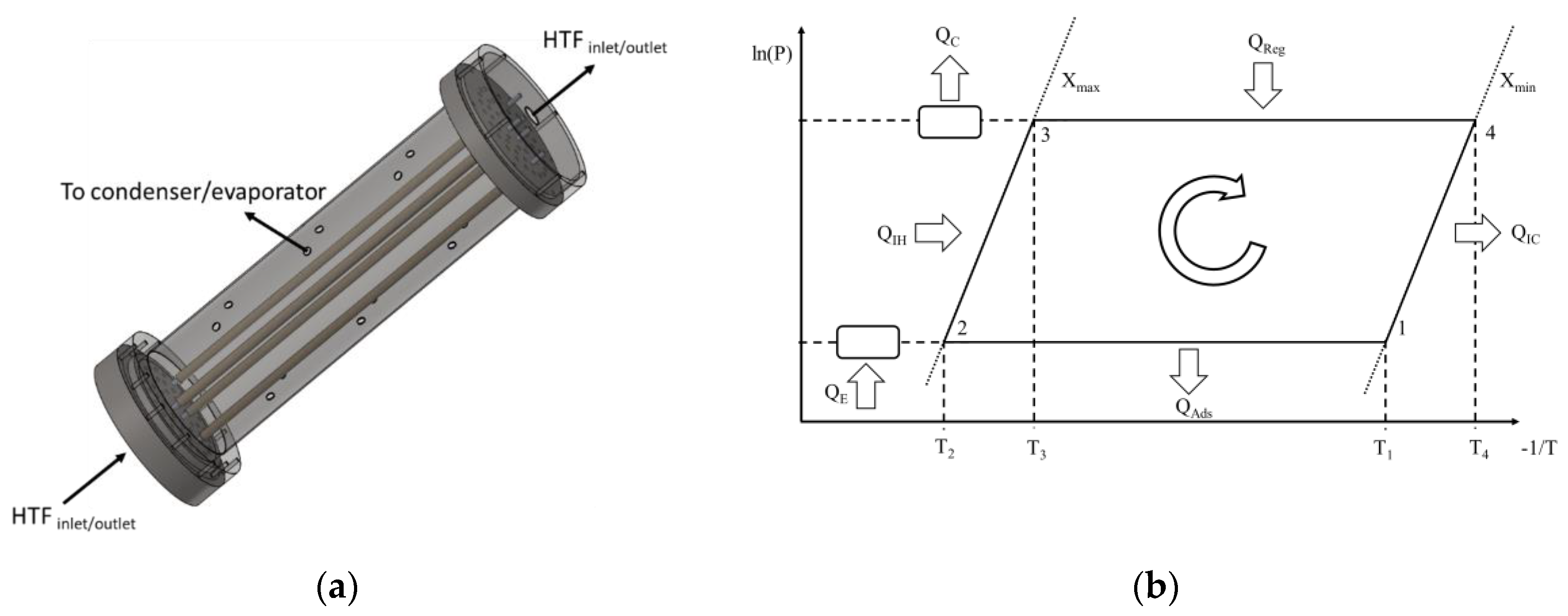
The adsorber used in this study consists on a set of metal tubes with a coating of adsorbent material on their outer surfaces. The RD2060 silica gel type from Fuji Silysia Chemical LTD is considered. It is mixed with a binder and then layered on the outer metal tubes’ surfaces until the desired thickness is obtained. The effect of the binder is accounted for by adjusting the heat and mass transfer coefficients, based on values reported in the literature for such coatings. The silica gel mixing with a binder to form an external coating on the metal tubes improves the metal–adsorbent heat transfer coefficient and the coating thermal conductivity. On the other hand, the mass transfer resistance is increased by mixing the silica gel with the binder. However, since the coating thickness is small, mixing the adsorbent with the binder will have more benefits than hindrances on the system’s performance [
32]. An air thermal treatment is applied to dry and stabilize the obtained coating. The coated tubes are enclosed into a cylindrical metal structure and connected to two metal joints, which seal them up in a vacuum chamber. The joints connect the interior of the tubes to the HTF’s circuit, enabling it to flow through the inside of the metal tubes. The vacuum chamber is alternately connected to an evaporator and a condenser during the adsorption and regeneration phases, respectively. A schematic of the aforementioned adsorber and the ideal thermodynamic cycle of the AHP are represented in
Figure 1. Not all the tubes are represented in order to keep the schematics clearer, more compact and perceptible.
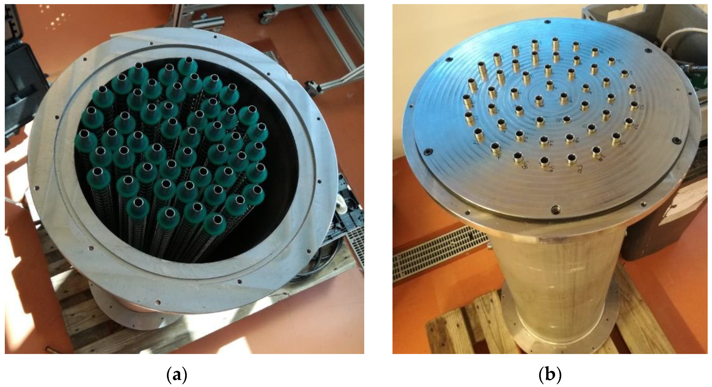
Figure 2 depicts the adsorber without the top lid, showing its core construction.
Table 1 reports some important dimensions of the coated tube adsorber, giving an idea of its size.
3. Physical Model
The adsorber’s dynamics are described by a distributed parameter model that considers two dimensions, which is extensively described in [
33]. The physical model has already been successfully used for adsorption cooling applications [
34]. The model resorts to the energy and mass conservation equations considering the developed adsorber, which give, respectively,
where
and
Darcy’s Law:
is used to describe the momentum balance, the Blake-Kozeny model, giving the adsorbent bed permeability [
35],
The evolution of the adsorbate concentration in the adsorbent material is obtained through the linear driving force (LDF) model [
36]
where
KLDF coefficient is obtained as
In its own turn, the equilibrium adsorbate concentration in the adsorbent,
Xeq, for the silica gel RD-water working pair is obtained as
The following main assumptions, which have already been used in previous studies, are considered in the model [
34]:
Adsorbent bed is homogenous;
The evaporator and the condenser are ideal heat exchangers with uniform pressures;
Adsorbate vapor phase behaves as an ideal gas and the adsorbed phase is considered to be liquid;
Specific heats of the adsorbate vapor and liquid phases are constants;
Adsorbate vapor around the adsorbent is saturated vapor;
Thermophysical properties of solid materials do not change with temperature;
Temperature, adsorbent content and pressure in the adsorbent bed do not change along the angular direction;
Considering these assumptions, the energy and mass conservation equations can be rearranged as:
Given that
, the variation of the HTF temperature along the radial direction is neglected,
. Considering that the HTF velocity is constant, the energy balance for the HTF is expressed as:
Since the metal tubes have high thermal conductivity and their thickness is small, their temperature is assumed constant along the radial direction,
. Thus, the energy balance equation for the metal tube is:
By using the method of lines, discretizing the partial derivatives in the axial and radial coordinates through finite difference methods, the set of partial differential equations is transformed in a set of ordinary differential equations. The resultant set of ordinary differential equations is solved using a solver suitable for stiff systems, ode15s, from Matlab R2020b [
37]. To obtain the solution for the ordinary differential equations, the following set of initial and boundary conditions were considered.
The adsorber’s performance is assessed through the evaluation of the COP and the SHP, evaluated respectively as:
where the adsorption, pre-heating, regeneration, and pre-cooling heats are calculated using the equations below, where the integration temperatures are those of the AHP’s thermodynamic cycle (
Figure 1b) [
26]
4. Results and Discussion
The analysis on the effect of the evaporator’s and the condenser’s temperature, cycle time, metal–adsorbent heat transfer coefficient, regeneration temperature, metal tube diameter, coating thickness and heat transfer fluid (HTF) velocity on the COP and SHP of the adsorber is presented. A series of reference parameters consistent with space and domestic water heating operating conditions were selected, which are summarized in
Table 2. Some properties were obtained from detailed material studies available in the open literature [
29,
30,
38,
39,
40]. All parameters assume their reference values except for the one being studied, which will be varied within a reasonable range. The analysis was carried out for two different operating conditions which translates into different heat sources and heat sink temperatures. Scenario A corresponds to pre-heating water in mild climates, the evaporator and condenser temperatures being set to T
e = 12 °C and T
c = 30 °C, respectively. For Scenario B, the working conditions were based on the European standard EN16147, which sets the testing and requirements for domestic hot water units. This standard applies to common (whole system) heat pumps. Since this work focuses on the adsorber, the working conditions have been adapted to allow its analysis. The temperature for the evaporator has been selected according to EN16147, considering an outside air unit at the mean temperature of 7 °C. The condenser temperature is set to 40 °C, which is considered as the reference hot water supply temperature in EN16147. Comparing the results obtained in this study with others available in the literature could not be carried out in detail given that no similar applications with sufficient details on all the parameters and coefficients could be found. In general, the COP values are in line with the values reported in the literature for silica gel-water working pairs under the reference temperatures. As for the specific heating power, it can be fine-tuned by changing the heat and mass transfer coefficients, cycle times, and phase change timings. These are the details that are not completely reported in the literature, preventing the authors from performing a useful and fair comparison.
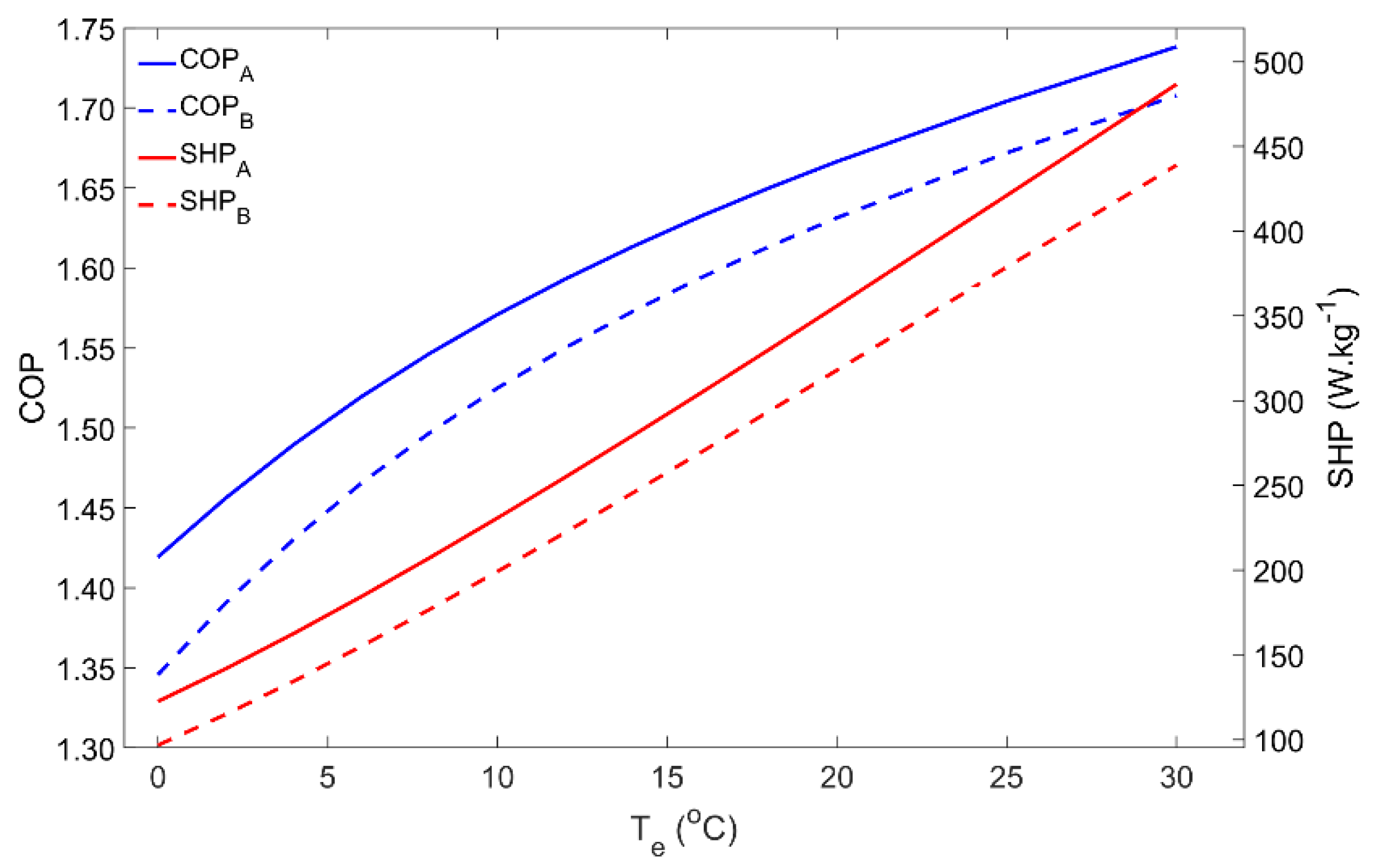
4.1. Influence of the Evaporator Temperature
During the adsorption phase, the pressure inside the system is determined by the evaporator temperature, which thus has a significant influence on the adsorber’s performance.
Figure 3 represents the impact of the evaporator temperature on the COP and SHP within the 0–30 °C temperature range. As is well-known in Thermodynamics, the COP of a heat pump increases for the higher evaporator temperatures. Low evaporator temperatures are associated with lower pressures in the adsorber during the adsorption phase, which reduces the adsorbing capacity and leads to low adsorbate flows. In addition, for lower pressures, the adsorption process is slower; thus, for the same cycle time, the amount of adsorbate that flows from the evaporator to the adsorber is significantly reduced. Notwithstanding that the performance for Scenario B is lower, which was expected from Thermodynamics, the influence of the evaporator temperature is similar for Scenarios A and B. For low evaporator temperatures (<5 °C) it might happen that the temperature of the HTF is not sufficiently low in order to reduce the adsorber’s pressure to the level of the evaporator’s pressure. In this case, the adsorbate cannot flow from the evaporator to the adsorber and the AHP can no longer work properly, resulting in a null heat pumping from the ambient to the hot water storage tank.
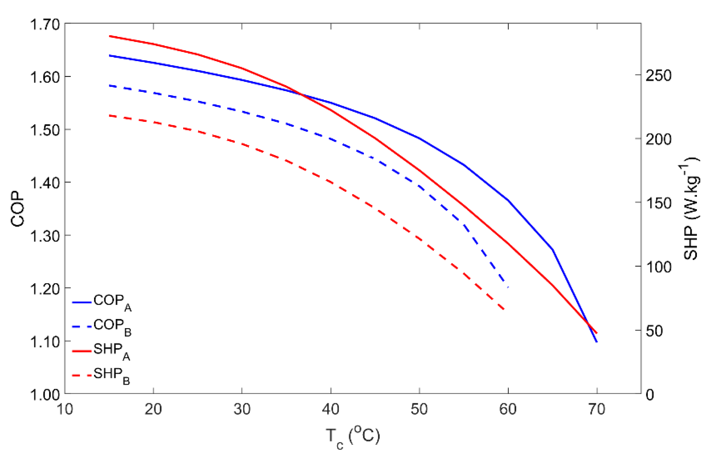
4.2. Influence of the Condenser Temperature
For domestic water heating applications, the condenser temperature is usually the temperature of the water inside the hot water storage tank. Thus, the condenser temperature was varied from 15 °C up to 70 °C and the results are reproduced in
Figure 4. Until approximately 40 °C for Scenario A and 30 °C for Scenario B, the COP and SHP slightly decreased with the condenser temperature. However, in both cases, for higher condenser temperatures, the adsorber’s performance greatly decreases and becomes very low when the water reaches its maximum temperature. The condenser temperature determines the pressure of the regeneration phase. The higher the pressure, the more time is required to raise the adsorber’s pressure from the evaporator pressure level up to the condenser pressure level, which, along with the slower adsorption kinetics for higher pressures, causes the SHP to fall down. On the other hand, for the same regeneration temperature, an increase in the pressure in the adsorber during the regeneration phase means that less adsorbate is desorbed, reducing the adsorbate flow in each cycle, which results in a lower COP. In an extreme scenario, the pressure in the condenser can be so high that the available regeneration temperature is not high enough to raise the adsorber’s pressure to that of the condenser, making it impossible to regenerate the adsorbent material and to properly operate the AHP. This issue was confirmed in Scenario B for condenser temperatures above 60 °C, when the highest temperature of the HTF during the regeneration phase is not able to increase the pressure in the adsorber to match the condenser’s pressure, resulting in an operating failure.
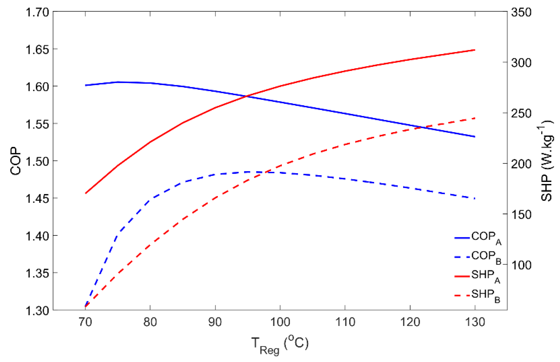
4.3. Influence of the Regeneration Temperature
The dependence of the adsorber’s performance on the regeneration temperature is represented in
Figure 5. Regeneration temperatures in the range of 70 °C to 130 °C were investigated. For Scenario A, COP reaches its maximum using regeneration temperatures around 75 °C and then it slightly decreases. For the silica gel–water working pair, it is not worth using regeneration temperatures above 75 °C if the objective is to maximize the output/input energy ratio. Nonetheless, using higher temperatures can be interesting since the SHP is increased due to the higher heat transfer rates (and faster heat transfer process) between the adsorbent material and the HTF. Using a higher regeneration temperature can reduce the size of the AHP system, while providing the same heating power with only a slight penalty on its COP. Meanwhile, increasing the regeneration temperature beyond the vaporization point of the HTF will require safety valves and a pressurized system to keep the HTF in the liquid phase in order to maintain high heat transfer rates. Concerning Scenario B, the maximum COP occurs for regeneration temperatures of approximately 95 °C, significantly decreasing for lower temperatures due to the higher pressure that is required during regeneration, which is associated with the higher condenser temperature when compared with Scenario A. Despite its lower values, SHP under the working conditions considered in Scenario B shows a similar behavior to that in Scenario A.
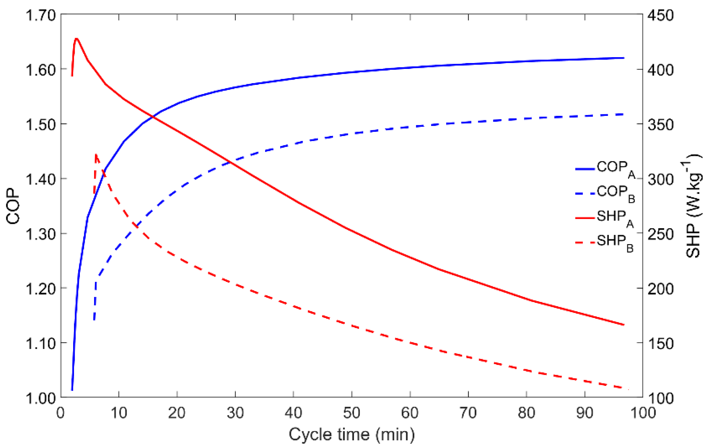
4.4. Influence of the Cycle Time
The cycle time is a key parameter since it allows the control and tuning of an AHP system. Moreover, as it is shown in
Figure 6, the COP and SHP have opposite behaviors when the cycle time is changed. In both Scenarios A and B, for low cycle times the COP is minimal whilst the SHP is the highest (apart the small increase for very short cycle times that do not allow the proper transition between the four phases of the adsorption cycle). Increasing the cycle time results in a higher COP until saturation occurs for cycle times above nearly 40 min, meaning that the adsorbent is adsorbing the maximum amount of adsorbate for the given operating conditions, leading to the maximum adsorbate flow within each cycle. On the other hand, when the cycle time increases, the SHP decreases, since the extra energy that is obtained by running longer (and more complete) cycles does not compensate for the increase in the cycle duration. Thus, a balance between the COP and the SHP must be found for the best AHP performance, which may be different for each application.
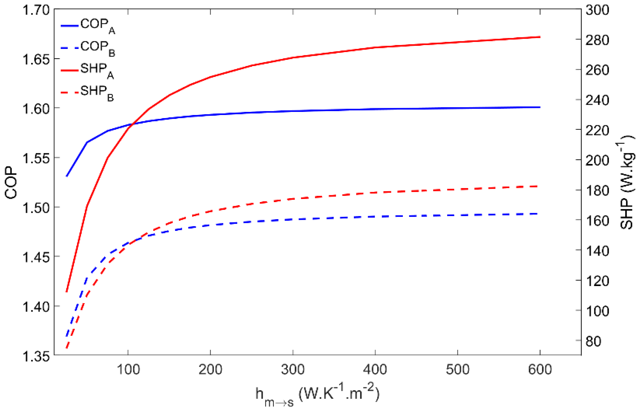
4.5. Influence of the Metal–Adsorbent Heat Transfer Coefficient
The metal–adsorbent heat transfer coefficient is a measure of the heat exchange effectiveness between the metal tube outer surface and the inner layer of adsorbent material coating the external surface of the adsorber’s tubes. Increased values of this parameter is one of the main reasons for using the coated tube setup. In addition, applying a thermal binder in the metal–adsorbent interface leads to increased values of this parameter.
Figure 7 represents the impact of changing the metal–adsorbent heat transfer coefficient from 25 W·m
−2·K
−1 up to 600 W·m
−2·K
−1 on the adsorber’s performance for Scenarios A and B. Since a long cycle time was selected, based on a long adsorption time (
tads in
Table 2), even low values of the metal–adsorbent heat transfer coefficient are enough to allow the achievement of approximately the maximum adsorption capacity, which results in an insignificant impact on the COP. Nonetheless, the influence of this parameter on the COP is more pronounced under Scenario B conditions, due to the higher difference between the evaporator and the condenser temperatures. However, since this heat transfer coefficient greatly conditions the rate of heat exchange between the HTF and the adsorbent material, the SHP greatly increases until the metal–adsorbent heat transfer coefficient attains approximately 200 W·m
−2·K
−1, and only slightly increases for
hm→s in the 200 to 350 W·m
−2·K
−1 range. Further increasing
hm→s does not have a significant impact on the adsorber’s performance since the adsorption kinetics become the limiting factor instead of the metal–adsorbent heat transfer coefficient. Apart from the inherent reduced performance under Scenario B conditions, there are no significant differences on the adsorber dynamics when operating under the different working conditions.
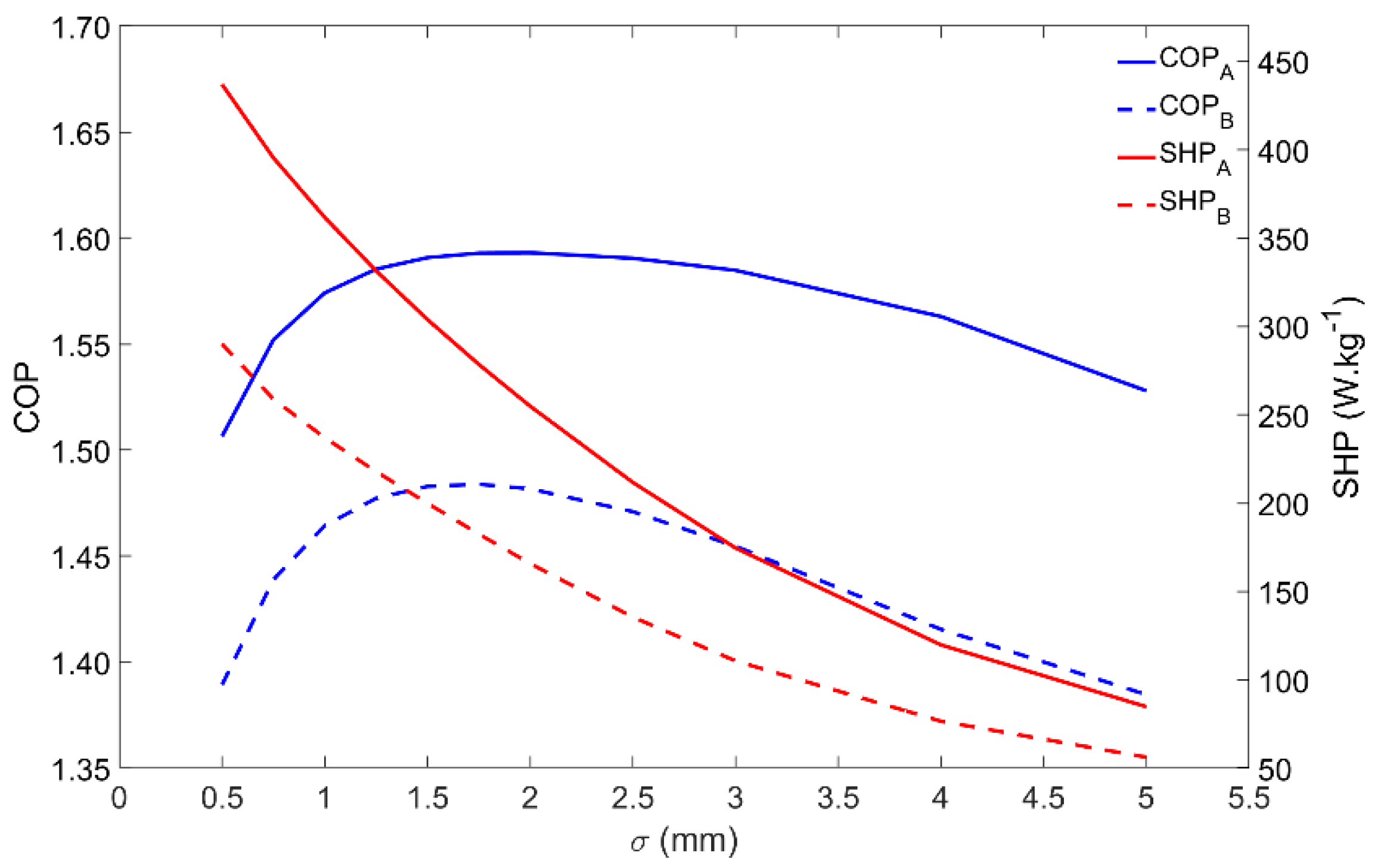
4.6. Influence of the Adsorbent Coating Thickness
Besides influencing the COP and SHP, the adsorbent coating thickness also changes the mass of adsorbent material that externally covers each tube. The influence of the adsorbent coating thickness on the performance of the adsorber is represented in
Figure 8. The COP is maximum for coating thicknesses in the 1.5–2-mm range, whereas the SHP decreases when increasing the coating thickness. Apart from the inherent performance reduction, the adsorber dynamics is similar under the Scenarios A and B conditions. Considering these performance indicators, there is no advantage in increasing the adsorbent coating thickness over 2 mm. Nonetheless, increasing the adsorbent thickness increases the mass of adsorbent that externally covers each tube, which results in a higher heating power, leading to a more compact adsorber, but with a lower energy efficiency. Depending on the AHP system’s requirements, the adsorbent thickness can be adjusted in order to result in a higher SHP, providing more heating power per unit mass of adsorbent, or to achieve higher energy efficiency by increasing the COP. However, one must be prudent not to reduce the thickness too much, since it will result in a tiny mass of adsorbent per tube, requiring a huge, and maybe unrealistic, number of tubes to satisfy the necessary heating power.
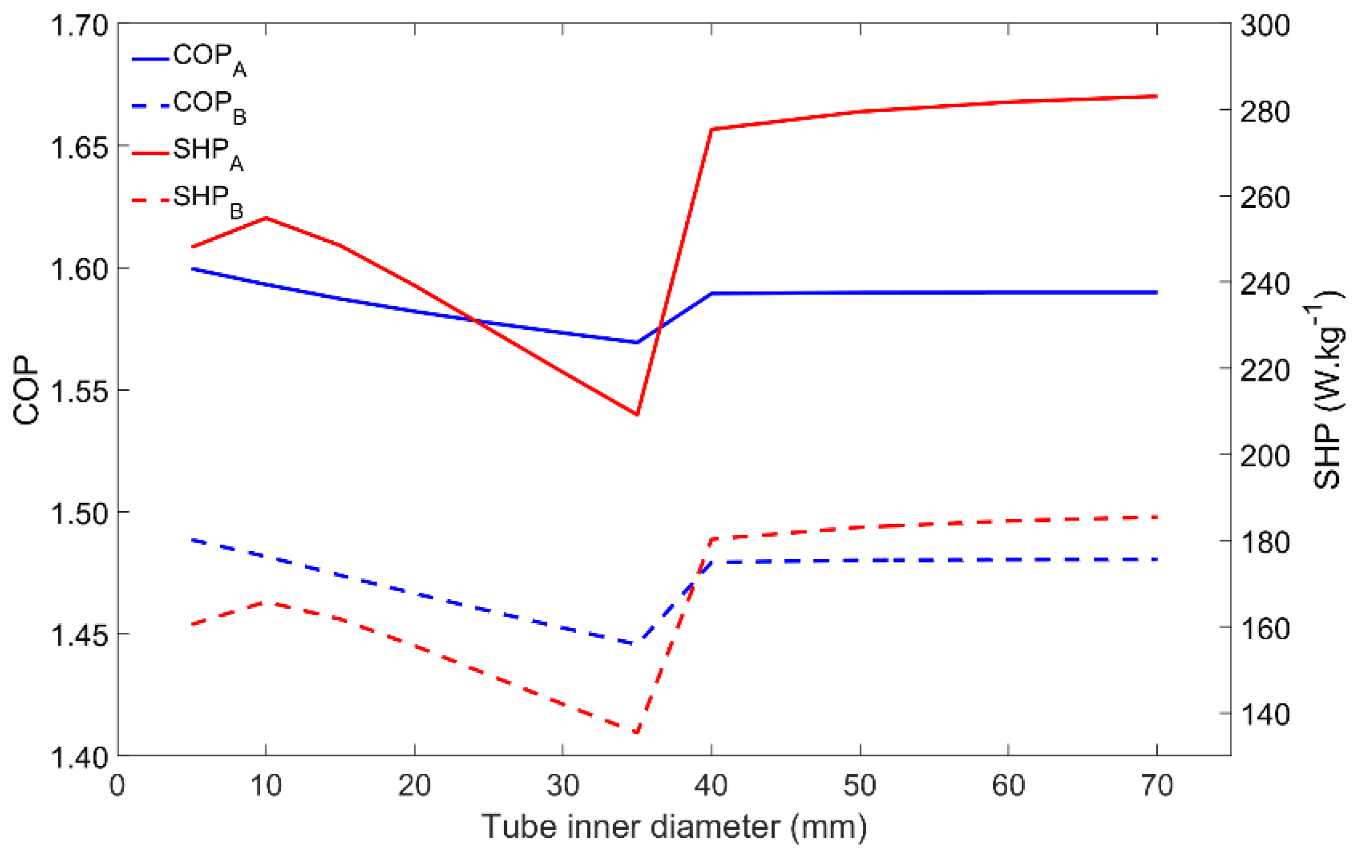
4.7. Influence of the Tube Diameter
Similar to the metal–adsorbent heat transfer coefficient, the metal tube’s inner diameter also affects other parameters. The heat transfer between the HTF and the metal tube, and also between the metal tube and the adsorbent material, is directly affected by the heat transfer areas, being thus affected by the metal tube’s diameter. Once the HTF’s velocity is set, the HTF’s mass flow rate increases as it increases the tube’s diameter. The adsorbent mass that externally covers each tube also increases as the tube’s diameter increases. The influence of the tube diameter on the adsorber performance is represented in
Figure 9. There are no evident differences between the adsorber dynamics when comparing the two tested Scenarios A and B. The most noticeable aspect is the performance increase that occurs when increasing the tube’s diameter from 35 mm to 40 mm. This behavior is due to the change in the HTF flow conditions in the tube from laminar to turbulent, which highly increases the heat transfer rate between the HTF and the inner surface of the metal tube. Even though the variations in the COP are not significant, the SHP has a maximum value for a diameter of 10 mm while under laminar flow conditions, which results in an optimal combination of the HTF’s mass flow rate and the adsorbent mass. For turbulent flow conditions, since the HTF mass flow rate is more than enough to provide/withdraw heat from the adsorber due to the more effective (and faster) heat exchange between the HTF and the metal tube, the SHP is higher. Increasing the tube’s diameter above 40 mm causes no significant impact on the performance of the adsorber. Although these results suggest the use of higher tube diameters, it might not be the best option since higher diameters lead to large adsorbers containing a low adsorbent mass, most of its volume being filled with the HTF.
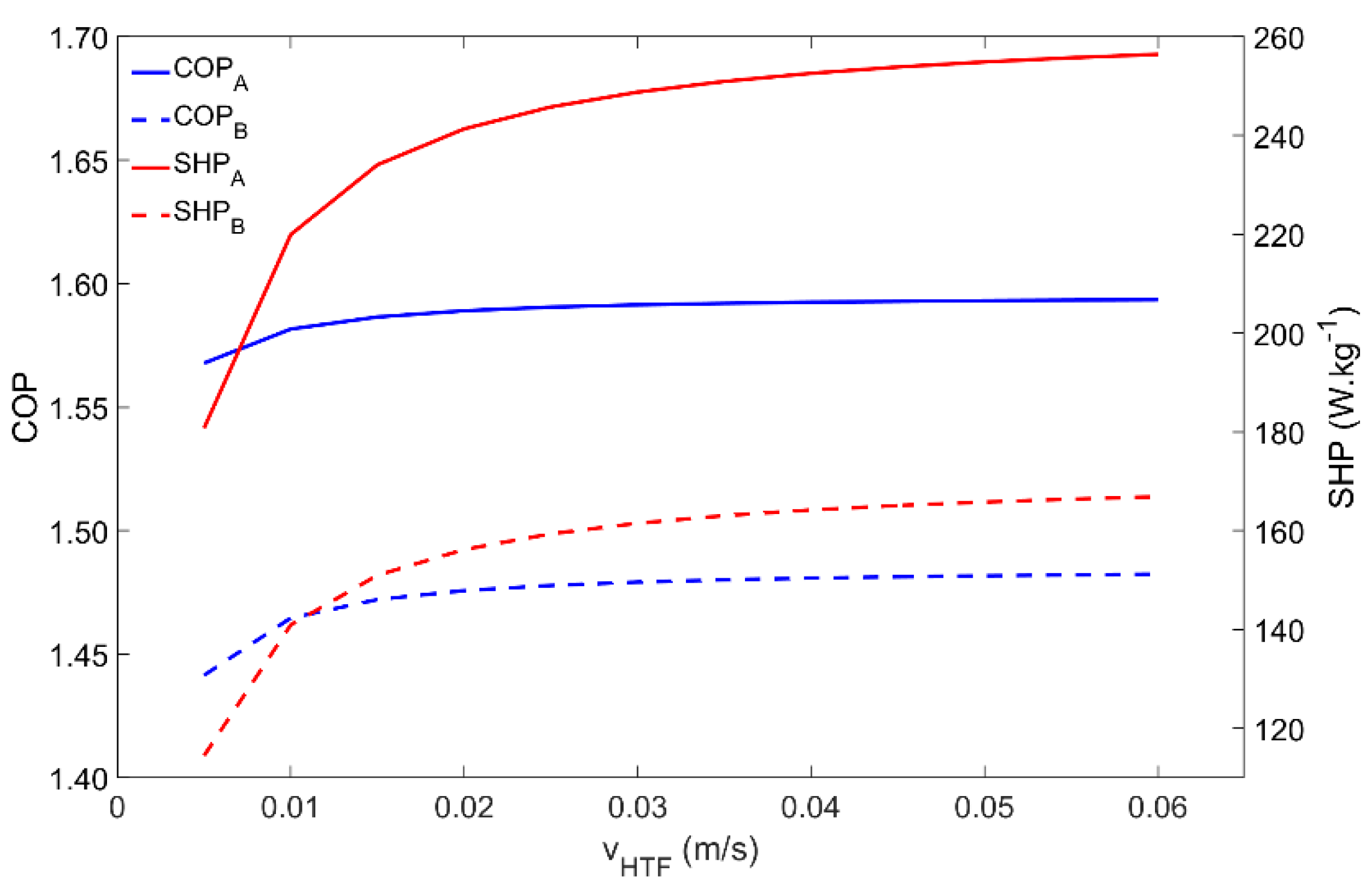
4.8. Influence of the Heat Transfer Fluid Velocity
The last parameter to be analyzed is the HTF velocity, the results of which are depicted in
Figure 10. The adsorber behavior is coincident for both Scenarios A and B. For the simulated conditions, the COP is not significantly affected by the HTF’s velocity since the adsorption and regeneration temperatures can always be achieved. However, the quickness of the process is highly affected, which is confirmed by the increase in the SHP with the HTF’s velocity. The SHP highly increases for HTF velocities within 0.005 m·s
−1 and 0.02 m·s
−1, slightly increases for HTF velocities from 0.02 m·s
−1 to 0.04 m·s
−1, and above that does not show significant increases. For higher HTF velocities, the adsorption kinetics become the dominant mechanism and further increases in the HTF velocity have no useful effect.
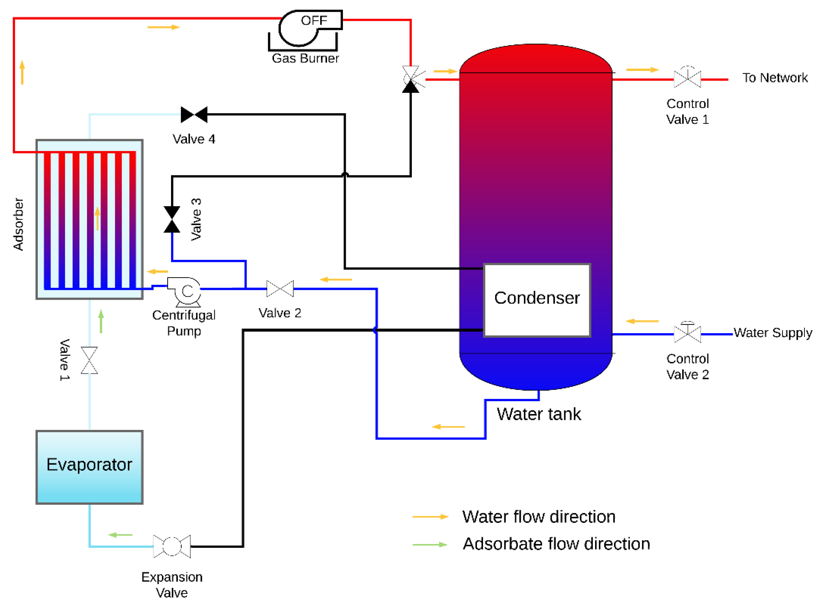
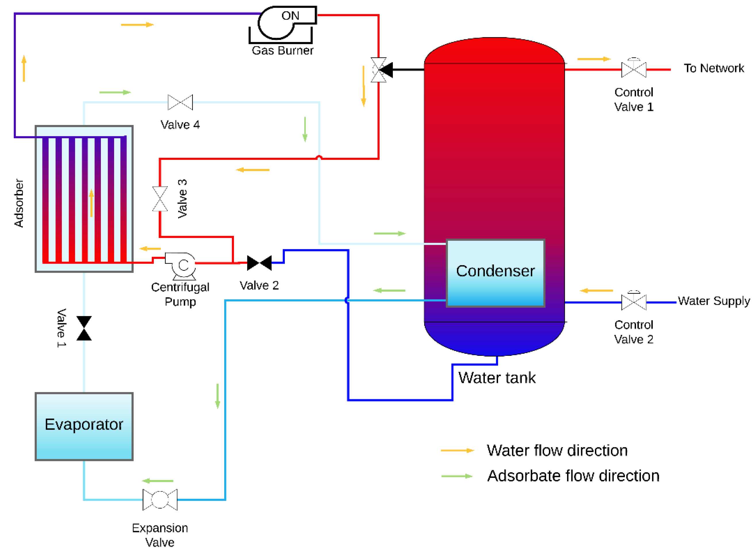
5. Adsorption Heat Pump System
The design of an AHP system suitable for space and domestic water heating is proposed, which contains the coated tube adsorber described and studied above and also the following main components: evaporator, condenser, heating element, water reservoir, expansion valve, centrifugal pump and the control valves. A condenser is placed inside the hot water reservoir, in this particular case the heating element is a natural gas burner; however, any other heating element can be used under the condition that heat is provided at a temperature above the regeneration temperature. The AHP system is represented in
Figure 11 and
Figure 12 during the adsorption and regeneration phases, respectively. The adsorbate flow is represented by green arrows, and the HTF (water) flow is represented by orange arrows. During the adsorption phase, the adsorbate flows from the evaporator to the adsorber. Cold water is taken from the bottom of the reservoir, circulated through the adsorber’s tubes to be heated and returned back to the top of the reservoir, transferring the adsorption heat from the adsorber to the water reservoir. During the regeneration phase, valves V
1 and V
2 are closed, valves V
3 and V
4 are opened, and the three-way valve shifts the flow from the reservoir towards valve V
3. The water flows from the adsorber to the gas burner, which is switched on, and back through the adsorber as hot HTF, providing heat to regenerate the adsorbent. At the end of the regeneration phase, the remaining circulating hot water is delivered to the top of the water reservoir. The supply water enters the reservoir at its bottom and the hot water is withdrawn from the top, where its temperature is higher, taking advantage of the thermal stratification effect.
The proposed AHP system resorts to a gas burner as a high temperature heat source. The gas-heated water can be used to regenerate the adsorbent or to be directly discharged into the hot water reservoir, depending on the temperature of the water in the reservoir. When the AHP effect is used to heat the water in the reservoir, the proposed heat pump system has the advantage of using the low temperature heat, received for free from the ambient, in addition to the heat received from the heating element. Another feature of the proposed system is that it can work as a direct gas water heater to provide hot water faster when a high or unpredicted hot water demand occurs, in this case without taking advantage of the heat pumping effect. The hot water leaving the reservoir can then be distributed through space heating circuits or could be used as domestic hot water.
The development of a model that considers all components of the AHP system, describing the entire system’s dynamics, will allow us to obtain the whole system’s performance. The adsorber’s performance when integrated in a real AHP system will probably be different when considering constant temperature and pressure in the evaporator and in the condenser during each of the different phases within each cycle. Additionally, in a real system, the adsorption and regeneration temperatures within each cycle are also changing. In the future, efforts will be made to develop a model capable of predicting the COP and SHP of the complete AHP system.
The developed system can also be operated in a heat storage mode. When operated in subsequent cycles, the AHP is continuously storing sensible heat in the water reservoir. In many countries worldwide, the price for electricity or natural gas varies for different hours during the day, being cheaper during the hours with a lower energy demand and more expensive during the peaks of daily energy consumption. An effective way to reduce the energy cost of households is to use energy during low demand periods. The proposed system can be regenerated during these periods, releasing condensation heat that is stored in the water reservoir, closing valve V4 when the adsorbent material is fully regenerated, keeping the system on halt and ready to later release the heat of adsorption. When hot water is demanded during high energy price periods, the system can begin the adsorption phase by opening the valve V1 and provide heat that was stored during cheaper periods. During adsorption, latent heat is captured in the evaporator and stored in the adsorbent bed, being released when the subsequent regeneration phase is started. This strategy of integrating adsorption technologies with the common instant heating devices is an effective way of reducing the energy costs of households.
6. Conclusions
Several governing parameters of a coated tube adsorber for an AHP suitable for space and domestic water heating were analyzed under different working conditions. Results show that high evaporator temperatures and low condenser temperatures lead to better performances, which was already expected considering the Thermodynamic lessons. However, kinetics of the adsorption process and the heat transfer between the heat transfer fluid and the adsorbent material need to be considered, as the AHP operates out of the equilibrium conditions considered in those Thermodynamics lessons. For all parameters investigated, the adsorber performs worse under the Scenario B working conditions, which could be foreseen by a thermodynamic evaluation due to the increased evaporator–condenser temperature difference. The adsorber dynamics are consistent between the two tested Scenarios for all parameters, except for the regeneration and condenser temperatures. The adsorber cannot operate for condenser temperatures above 70 °C and 60 °C for Scenarios A and B, respectively, since the pressure inside the adsorber cannot be sufficiently increased to achieve the pressure in the condenser. The maximum COP is obtained for regeneration temperatures of about 75 °C and 95 °C for Scenarios A and B, respectively, whilst the SHP increases with the regeneration temperature. The COP and the SHP have opposite behaviors with the change of the cycle time. Short cycle times lead to higher SHP but lower COP, whereas long cycle times result in a higher COP and a lower SHP. The cycle time must be adjusted in order to achieve the optimal balance between the COP and the SHP, to give to the AHP the best performance depending on its specific application.
Although the metal–adsorbent heat transfer coefficient does not significantly affect the COP, the SHP highly increases until it reaches 200 W·m−2·K−1. This is the main reason for the use of adsorbent coatings, since they can provide metal–adsorbent heat transfer coefficients up to ten times higher than packed beds. The SHP can also be improved by using thinner adsorbent coatings, but this requires an adsorber with a larger number of tubes. The inner diameter of the metal tube and the HTF’s velocity can both be used to improve the performance of an AHP system. Turbulent flow conditions result in a higher SHP; however, in order to set this condition using low HTF velocities, the tube’s diameter needs to be too large, which will result in high volume adsorbers.
Future developments include a model that considers the whole AHP system illustrated in
Figure 11 and
Figure 12, and not only the adsorber. Understanding the dynamics of the complete AHP system and predicting its performance considering several working modes and conditions will contribute to improved AHP systems that can be made available in the market faster and at lower costs. The heat storage capacity of AHP systems can be used to reduce a household’s energy costs as well as to boast the effectiveness of using intermittent renewable energy sources.


