Article

Efficiency of Different Balcony Slab Modernization Method in Retrofitted Multi-Family Buildings

by
Beata Sadowska
1,* and
Piotr Bieranowski
2
1
Department of Energy Efficient Construction and Geodesy, Faculty of Civil Engineering and Environmental Sciences, Bialystok University of Technology, Wiejska 45E Street, 15-351 Bialystok, Poland
2
Department of Mechanics and Basic Machine Design, University of Warmia and Mazury in Olsztyn, Oczapowskiego 2 Street, 10-719 Olsztyn, Poland
*
Author to whom correspondence should be addressed.
Energies 2021, 14(20), 6666; https://doi.org/10.3390/en14206666
Submission received: 27 August 2021 / Revised: 3 October 2021 / Accepted: 11 October 2021 / Published: 14 October 2021
(This article belongs to the Special Issue Energy Efficiency Improvement Measures in Buildings)

Abstract

:
Many buildings have considerable thermal bridges at the junction of balcony slabs with walls. To achieve the new EU directive targets related to energy efficiency, greater attention should be paid to such design details. This study analyzes the efficiency of traditional balcony slab modernization methods, the use of modern insulation materials and a new alternative system: an added self-supporting light balcony system (LKBD) in retrofitted large-panel buildings. The main objective was to capture cost-effective renovation methods from both the heat loss reduction perspectives and risk of surface condensation. The analyses, carried out in four buildings, have shown that at current costs, the thermal modernization of balconies is not economically efficient (SPBT > 98.4 years). However, it is necessary because leaving the balcony slabs without insulation or only insulating them from the bottom carries the risk of surface condensation. The most cost-effective renovation method is to insulate the balcony slabs from below and above with the thickest possible XPS layer (SPBT = 98.4 years; 107.4 years). Replacing XPS with modern material increases SPBT by almost 50%, for the LKBD system, SPBT = 269.2–281.5 years. More favorable energy and economic effects related to the reduction of balcony thermal bridges were achieved in the wall with lower insulation.

1. Introduction

One of the priorities of countries around the world is to increase the energy efficiency of the building sector. In 2019, the final global energy consumption for building operations was approximately 130 EJ, which is nearly 30% of the total final consumption, and a further 21 EJ for buildings and construction or 5% of the total demand [1]. While the total final energy consumption of the global buildings sector in 2019 remained at the same level compared to the previous year, the share of this sector was higher than in the previous years, by 1% compared to 2017 and by 7% from 2010 [2]. Policies and measures implemented by individual countries over the past 20 years have improved the efficiency of their building stock but were not adequate to outpace demand growth that was driven by strong floor area and population expansions. The buildings and the construction sector are also responsible for almost 38% of total global energy-related CO2 emissions [1]; therefore taking action in this sector is critical to fulfil Sustainable Development Goals.
In the European Union, long-term energy and climate goals are defined in the EU’s Long-Term Strategy [3]. In addition to the general roadmap to emission neutrality of the building stock by 2050, the European Commission has set policy targets and regulations to ensure energy efficiency improvement of the European building stock. The main legislative and policy tool in the EU, which focuses on both new and existing buildings, is the Energy Performance of Buildings Directive (2010/31/EPBD). The Directive was amended in 2018 [4] to accelerate the cost-effective renovation of existing buildings by 2050 as well as to support the modernization of all buildings with smart technologies and make a clearer link to clean mobility. In October 2020, the European Commission launched a renovation wave [5], saying it would aim to double the EU’s annual rate of energy-related building renovations, which is currently just 1%, upgrading 35 million buildings by 2030. According to the Joint Research Centre Report [6], a large share of today’s EU building stock was built without any energy performance requirement. Approximately one-third of the EU building stock is over 50 years old, and more than 40% was built before 1960. Almost 75% of it is energy-inefficient according to current building standards. Therefore, it is important to continue analyses and research on effective methods of thermal modernization. Since Europe’s building stock is heterogeneous, as emphasized in [5], certain technical solutions are specific to individual countries or regions. This is due to climate, environment, landscape, or economic and social structure.
In Poland, as of 1 January 2020, the total number of buildings was 14,189 thousand [7]. Most of them, especially buildings erected before 1991, have a high energy demand. Over 70% of single-family buildings are also characterized by low energy efficiency [8]. Generally, one of the largest energy consumers in Poland are households; their share in total energy consumption in 2018 was 18.2% [9]. In Polish residential buildings most of the energy is still used for space heating, despite a downward trend (similar to that seen in the rest of Europe) resulting from the improvement in the quality of their thermal properties through the adoption of increasingly stringent energy regulations.
There are many methods of improving the energy performance of buildings but the best results are achieved by comprehensive thermal modernization. Properly prepared, the deep thermal modernization of a building in Poland, located in a cold, heating-dominated climate, can result in final energy savings of up to 65% [10]. A similar average reduction in energy consumption (of 66.4%) was reported in research published by the International Energy Agency [11], in which 26 case studies of buildings around the world were collected and analyzed. This document contains interesting information on the implemented energy renovation technologies, in terms of both technical parameters and costs. The conducted analysis clearly shows that it is necessary to retrofit mechanical systems by implementing technology bundles in concert with a well-planned building envelope renovation. One of the most common defects in the implementation of extra insulation on building facades is the lack of appropriate solutions at the junction of window frames or balcony slabs with walls. These and other thermal bridges are responsible for heat loss in winter [12] and heat gain in summer [13]. In addition, thermal bridges can cause the appearance of areas with mold and condensation due to the reduction of the internal surface temperature [14].
While it is not possible to obtain overall results, there are studies that have quantified the effect of thermal bridges on the energy needs of buildings in various cases.
So far, a number of numerical and experimental research studies have been published on both linear and point thermal bridges in buildings. The share of thermal bridges in heat transmission losses was investigated. It is dependent on the climate and construction. According to Theodosiou et al. [15], linear thermal bridges can have a substantial effect on the overall heat transmission through the building envelope, as large as 30% or even higher in cases of complex morphological characteristics or extended balconies. Point thermal bridges, although very limited in most building constructions, can also have a similarly significant impact on overall heat loss, e.g., in advanced building partitions, such as ventilated facades [16,17]. Although it is not possible to obtain general results, there are studies that have quantified the effect of thermal bridges on the energy needs of buildings for different cases. For example, Ramalho de Freitas and Grala da Cunha assessed how the impact of the thermal bridges of reinforced concrete structures of a Brazilian building could vary its energy performance by up to 20% [18]. The results of Theodosiou and Papadopoulos [19] show that even if the construction presents high insulation levels, the heating need in Greece can be 30% higher than the one calculated without considering the thermal bridge effects. Ge et al. [20] suggested that the existence of thermal bridges increases the annual space heating energy demand from 38 to 42% under the cold climates in Canada and the improvement of building envelope connection details can reduce the contribution of thermal bridges from 3 to 4%. Evola et al. [21] studied the effect of thermal bridges in two semi-detached houses located in a mild Mediterranean climate, determining that the improvement of thermal bridges resulted in a 25% reduction in the heating load and an 8.5% reduction in cooling load; the discounted payback period referred to the additional costs of construction and refurbishment was also assessed. Some studies have a more multidisciplinary perspective. Bienvenido-Huertas et al. [22] demonstrated the energy improvement (more than 18% for heating and 2.8% for cooling in a case study located in the south of Spain) achieved by patents for the thermal bridge of the slab front and analyzed the possible performance of the thermal bridge in future years (2020, 2050, and 2080). In subsequent studies, Bienvenido-Huertas [23], in addition to the linear thermal transmittance of the thermal bridges and energy simulations of an existing building in Spain, analyzed two climate scenarios (current and future). The economic effects, as well as the energy and emissions produced in the manufacture and construction stages, were also assessed.
Among all types of thermal bridges, the exposed balcony slab produces the most challenging thermal bridging [24]. One of the solutions to the thermal bridge problem in the case of cantilevered concrete balcony slabs, which is the solution most often used in buildings, is the introduction of thermal breaks. They do not completely stop heat transfer through the balcony-wall connection because high rates of heat transfer occur through the metal reinforcement; however, they substantially reduce heat transfer through the remaining part (80–90%) of the cross-sectional slab area. Ge et al. [25] confirmed that with the introduction of the balcony thermal break, the overall heat transfer at the balcony slab is significantly reduced and the interior floor surface temperature is greatly increased under typical winter design conditions in Toronto. The impact on the overall U-value of the building envelopes can be improved from 9–18% and the space heating energy consumption may be reduced from 5–13%. The results of research by Susorow et al. [26] showed a similar level of improvement in the effective thermal resistance of the curtain wall cladding assembly in a multi-family building in Chicago (by approximately 14%). However, the predicted effect of the use of thermal breaks on the annual energy consumption was significantly lower than in [25]. In several more generic building designs with simpler geometries, it was less than 2% [26]. The authors suggested the need to consider the use of thermal break products in combination with other energy efficiency strategies to achieve high performance enclosures. Research has also been conducted on the use of materials that are less thermally conductive than stainless steel reinforcement like fiber-reinforced polymer [27] or aramid fiber [28]. Study [28] showed that new thermal breaks have low values of linear thermal transmittance (Ψ < 0.15 W/(m·K)). They also increase the temperature at a particular point on the slabs compared to conventional cases by a few percent [25,27]; however, they are not applicable to existing buildings. In the case of building retrofit, solving thermal bridges is often an issue, especially where external insulation or other solutions are not applicable because of architectural constraints.
The economic and technical feasibility, as well as the energy aspects of different retrofit operations on the balconies of residential buildings located in northern Italy, were investigated by Pansa et al. [29]. Two different insulation levels were considered (corresponding to an extra insulation of 8 and 16 cm, λ = 0.040 W/(m·K)). The external walls of the analyzed apartment block building with 16 cm thick insulation on the outside were characterized by a U-value equal to 0.20 W/(m2·K), which corresponds to the current requirements in Poland [30]. The linear thermal transmittance of the connection of the balcony slab with the wall were as follows:
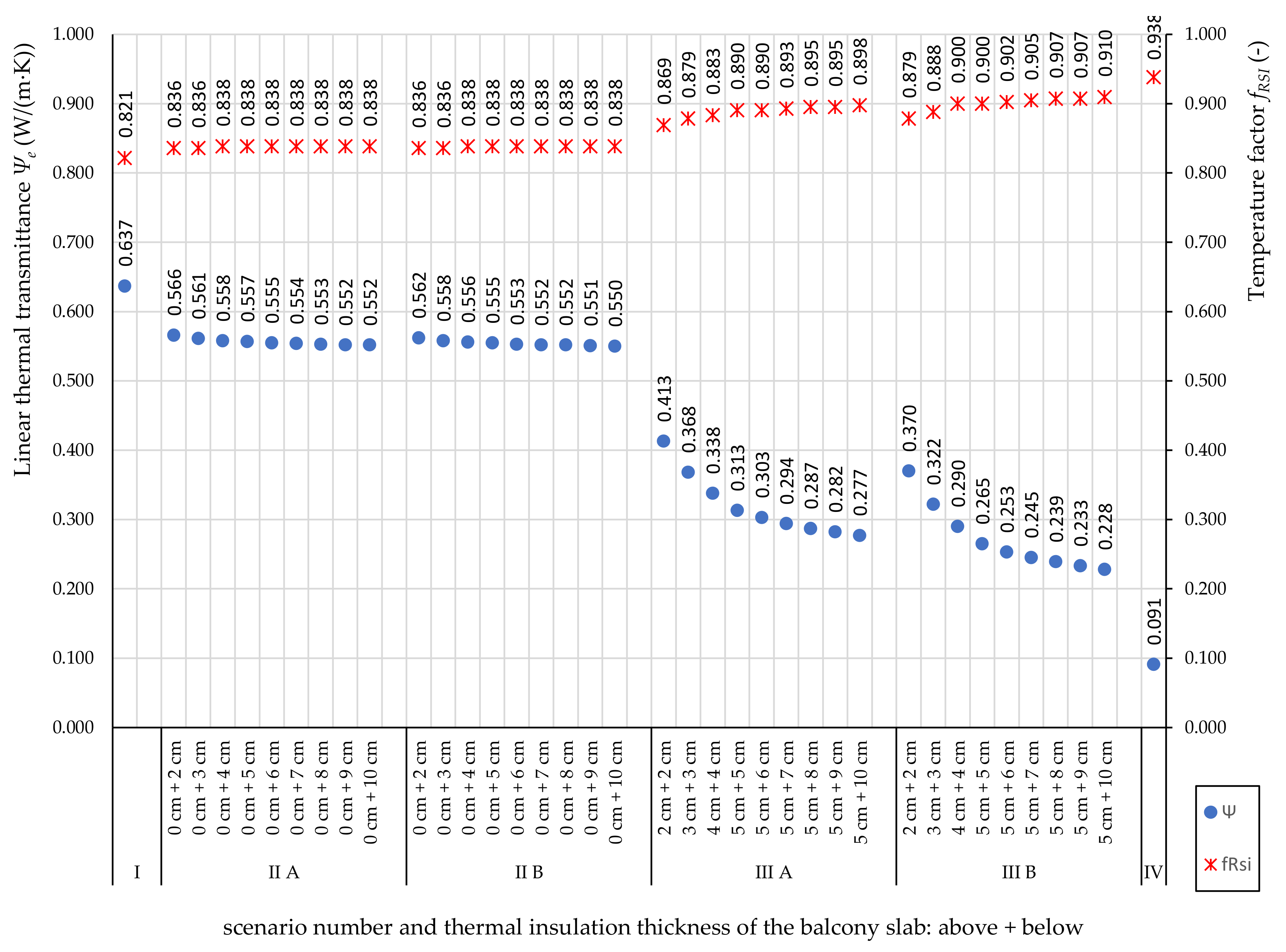
  • 0.63 W/(m·K) in the case with no insulation of balconies;
  • 0.54 W/(m·K) in the case with balconies insulated with 4 cm EPS on the lower side;
  • 0.42 W/(m·K) in the case with balconies insulated with 4 cm EPS on the lower side and 3 cm on the upper side;
  • 0.326 W/(m·K) in the case of the demolition and reconstruction of balconies, which was made by structural light-weight concrete and steel reinforcing bars fixed to existing concrete beam with chemical bolts;
  • 0 W/(m·K) in the case of the demolition and reconstruction of balconies, which was made by external steel structures fixed by chemical bolts.
The determined linear heat transfer coefficient for new balconies with a thermal break in new buildings was 0.18 W/(m·K). It has also been found that the transformation of existing balconies into sunspaces seems to be a good solution to save energy, but this option must be carefully designed. The results of this research also showed that in the case of partitions with better thermal insulation, the percentage share of bridges in heat loss is higher than in partitions with lower thermal insulation. A similar relationship was noted by Ilomets et al. [31]. They found that the relative percentage of thermal bridges after renovation increases and, additionally, the negative impact of the thermal bridges of certain junctions cannot be compensated with thicker wall insulation.
The results obtained in the studies described above can be compared with the classification of thermal bridges according to the Building Research Institute [32]. The influence of thermal bridges (with their dimensioning system based on external and internal dimensions) has been divided into four groups:
  • Negligible impact: Ψi,e < 0.1 W/(m·K).
  • Low impact: 0.1 ≤ Ψi,e < 0.25 W/(m·K).
  • High impact: 0.25 ≤ Ψi,e < 0.5 W/(m·K).
  • Very high impact: Ψi,e ≥ 0.5 W/(m·K).
This comparison confirms the very high or high impact of the exposed balcony slabs, except for the use of thermal breaks, the impact of which can be assessed as low.
The values of linear thermal transmittance of thermal bridges in building envelopes with different levels of thermal insulation can be found in the catalogs. However, they are dedicated mainly to new buildings, in which modern solutions and materials are used, e.g., cellular concrete [33] or lime-sand bricks [34]. On the other hand, the International Standard ISO 14683 [35], which has been adopted in some countries, including Poland, without developing a more detailed atlas of the building element junctions, contains default values of linear thermal transmittance for the connection of a wall and a balcony slab only for a balcony slab without thermal insulation (they range from 0.70 W/(m·K) for walls without thermal insulation to 0.95 W/(m·K) for walls with thermal insulation). In addition, the thermal bridges atlas, provided in this standard does not include data for assessing the risk of surface condensation or mould growth in these areas.
An interesting study was proposed by Capozzoli et al. [36]. They developed a non-linear regression model for each analyzed thermal bridge, including balcony bridges and prepared the tables with linear thermal transmittance as a practical and useful tool for designers and policymakers. However, the wall-balcony connection was not analyzed in terms of thermal insulation of balcony slabs, but only various configurations of wall structures.
Therefore, the aim of this study was to evaluate the efficiency (energy, economic and usable) of different methods of retrofitting balcony slabs. It was decided to deal with a group of concrete large panel-structured apartment buildings built between the 1960s and 1990s as they are the most common apartment building type in many European countries, e.g., the Scandinavian countries, Estonia, Russia and numerous Eastern and Northern European countries [37], and they will be renovated in the coming years [4,5,7]. These issues have also been the research area of interest of the authors of this article. In 2015, Bieranowski [38], after preliminary thermal imaging tests of the precast cantilever balcony support in an OWT-67 large-panel system, subsequently extended by mycological analyses [39], proposed a new alternative wall-balcony connection system: an added self-supporting external element—the light balcony system (LKBD). Sadowska, based on field research, analyzed the effects of thermal bridges in large-panel buildings before and after thermal modernization, on heat loss [40]. Analysis in this field was also undertaken by other authors, but with the thermal insulation of the walls much higher than currently required. For example, in Grudzińska and Ostańska [41], the thermal transmittance coefficient of a wall without thermal bridges is U = 0.30 W/(m2·K), and in the paper Steidl and Krause [42] U = 0.363 W/(m2·K), which exceeds the current requirements in Poland by over 50%.
However, there are no studies where the new LKBD solution has been profoundly analyzed in the context of heat loss and the risk of moisture occurrence and comparing it with other solutions in the current conditions of thermal protection of the building envelope. Thus, in this study, the efficiency of the LKBD system, as well as various insulation configurations of balcony slab, were analyzed in the light of the current requirements for building envelopes in Poland (in force 31 December 2020 [30]). This study also focused on the impact of the insulation layer thickness on the thermal bridging.
It has been noticed that, at current costs, the thermal modernization of balconies (if they are not damaged from the structural point of view) is not advantageous but is necessary because leaving the balcony slabs without insulation or only insulating them from the bottom carries the risk of surface condensation. Results obtained in this paper can be useful for energy audits, architects, or civil engineers. They shed light on the potential for energy renovation measures to be applied in existing buildings. This paper was grouped in four main sections. In the introduction, the context of the study is explained, and the relevant literature is referenced. The methodology section shows the different methodological details of this research. The results, its analysis, and comparison are shown in Section 3. The last section constitutes some of the main findings.

2. Materials and Methods

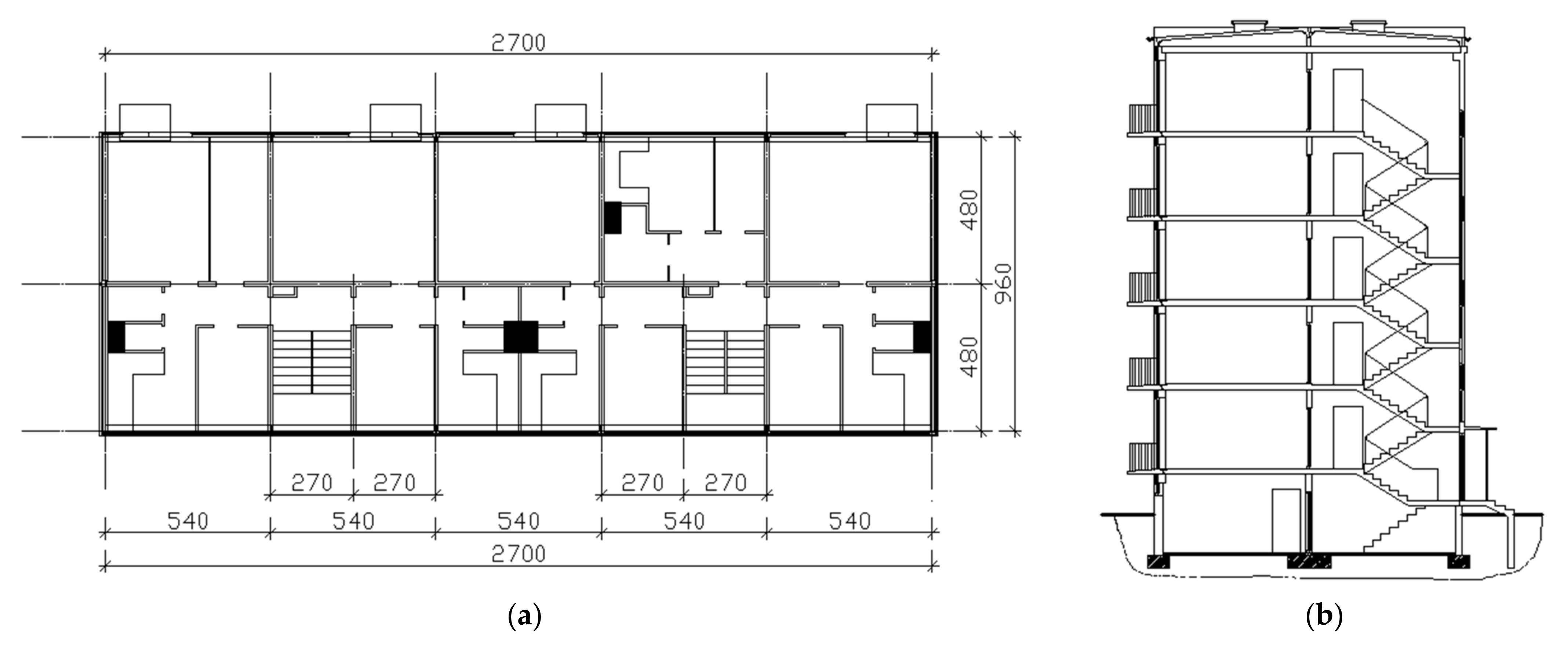
2.1. Case Study Housing Stock

Given the significant share of large-panel residential buildings in the existing building stock in Poland and other European countries [37], the need to increase the rate of energy-related building renovations [5] and the observed lack of care for proper insulation of balcony slabs during their thermal retrofitting [7,8], a group of typical residential buildings erected using this technology, was selected as the case study. This system comprises room-sized panels of precast concrete. The concrete panels are sandwich units, with an internal wall panel (loadbearing or not), an external façade panel and thermal insulation in between (50 mm or 60 mm thick). The construction and technological system of the housing construction with the symbol OWT-67 is shown in Figure 1 (version with two staircases).
One of the authors of this paper participated in the preparation of technical opinions on the correctness of thermal modernization of 40 large-panel multi-family buildings in the northeastern region of Poland. In these buildings, the facades and flat roofs were insulated, windows in staircases and basements were replaced, and the central heating system was modernized. In all cases, the balcony slabs were not insulated. Figure 2 shows a fragment of the facade of one of the examined buildings. The field measurements using infrared thermography showed thermal bridges in the places where the balcony slabs joined the wall.
The connections of non-insulated precast cantilevered balcony with the wall were areas with undoubtedly worse thermal parameters than the rest of the building envelope. This is proven by the temperature difference between the main surface of construction and the area of balcony connection. The same situation occurred in all 40 tested buildings. Similar research results were obtained by the second author of this paper for a building erected in a different location in Poland. In the study on non-invasive tests of precast cantilever balcony in the OWT-67 system [39], the average temperature difference was found within the interactions and outside the thermal impact area of the thermal bridge equal to 4K. In the aspect of the internal surface of the external wall, the difference was, on average, 8K on the longitudinal wall in the level of the floor and 3K within the prefabricated “Z” lintel beam.
From a group of 40 buildings, four five-story multi-family houses were selected to analyze the effectiveness of various methods of modernizing balcony slabs. These buildings had the same height, but a different number of staircases—from three to six. Their main data are given in Table 1.
The buildings under investigation were erected in the 1970s and were modernized between 2007 and 2009. Their shells were insulated using an External Thermal Insulation Composite System (ETICS), which is considered as the most popular insulation technique in terms of thermal bridge mitigation. The material for the thermal insulation of external walls (EWI) was expanded polystyrene (EPS) with a thermal conductivity of 0.04 W/(mK) and a layer thickness of 0.12 m to meet the requirements in force at that time.

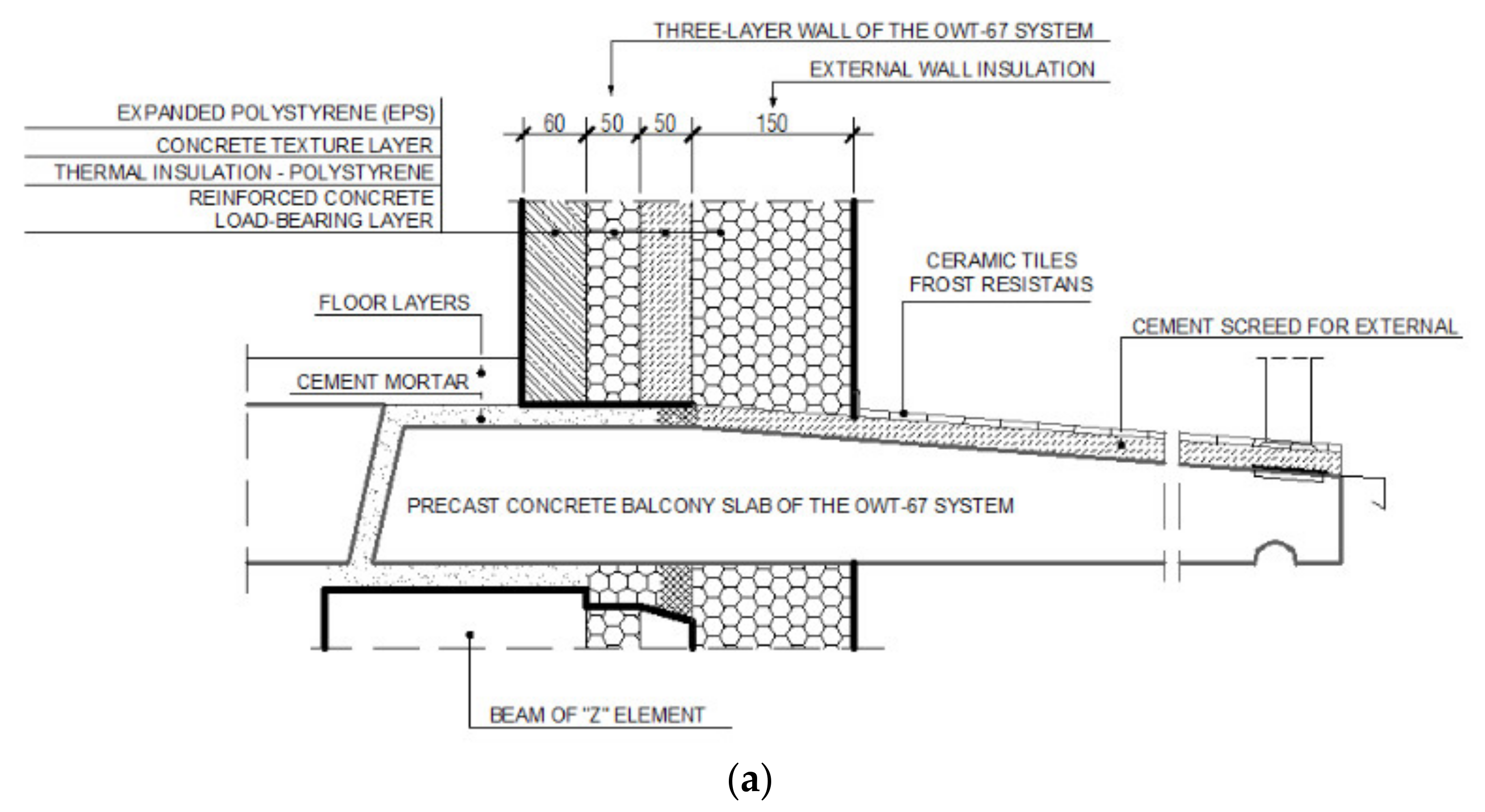
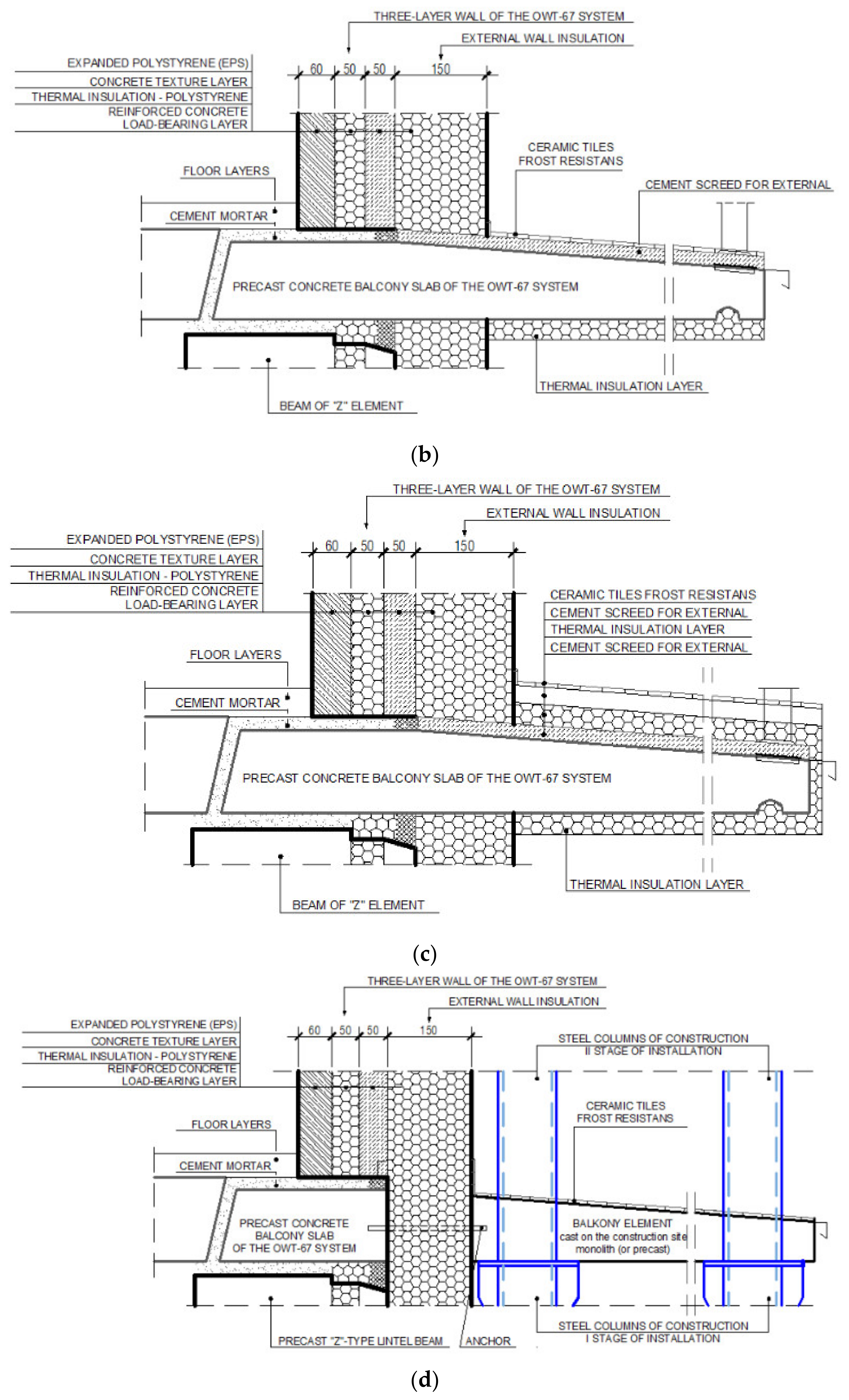
2.2. Considered Interventions on Precast Cantilever Balconies

One of the most problematic structural elements of large-panel buildings are the cantilevered balconies. The joints of the balcony slab with the wall are thermally broken, which leads not only to increased heat loss, but also to chilling the interior side of the slab. In air-tight, higher-humidity buildings (which is often observed in buildings after thermal modernization) it can quickly form condensation, causing mould to grow. Because of significant negative impact of the thermal bridging through the balcony slab on the energy performance of buildings, as the literature review revealed, in the article, the authors concentrated on various methods of the thermal modernization of balcony slabs in existing retrofitted buildings. The quantification of thermal bridges is among the most important activities carried out in energy audits. They should also be considered in the design for the thermal insulation of a building, which can be helped by the analyses proposed in this article.
Four different scenarios, shown in Figure 3, were assumed to assess how the methods of insulating cantilevered balconies affected the thermal bridges and the risk of condensation:
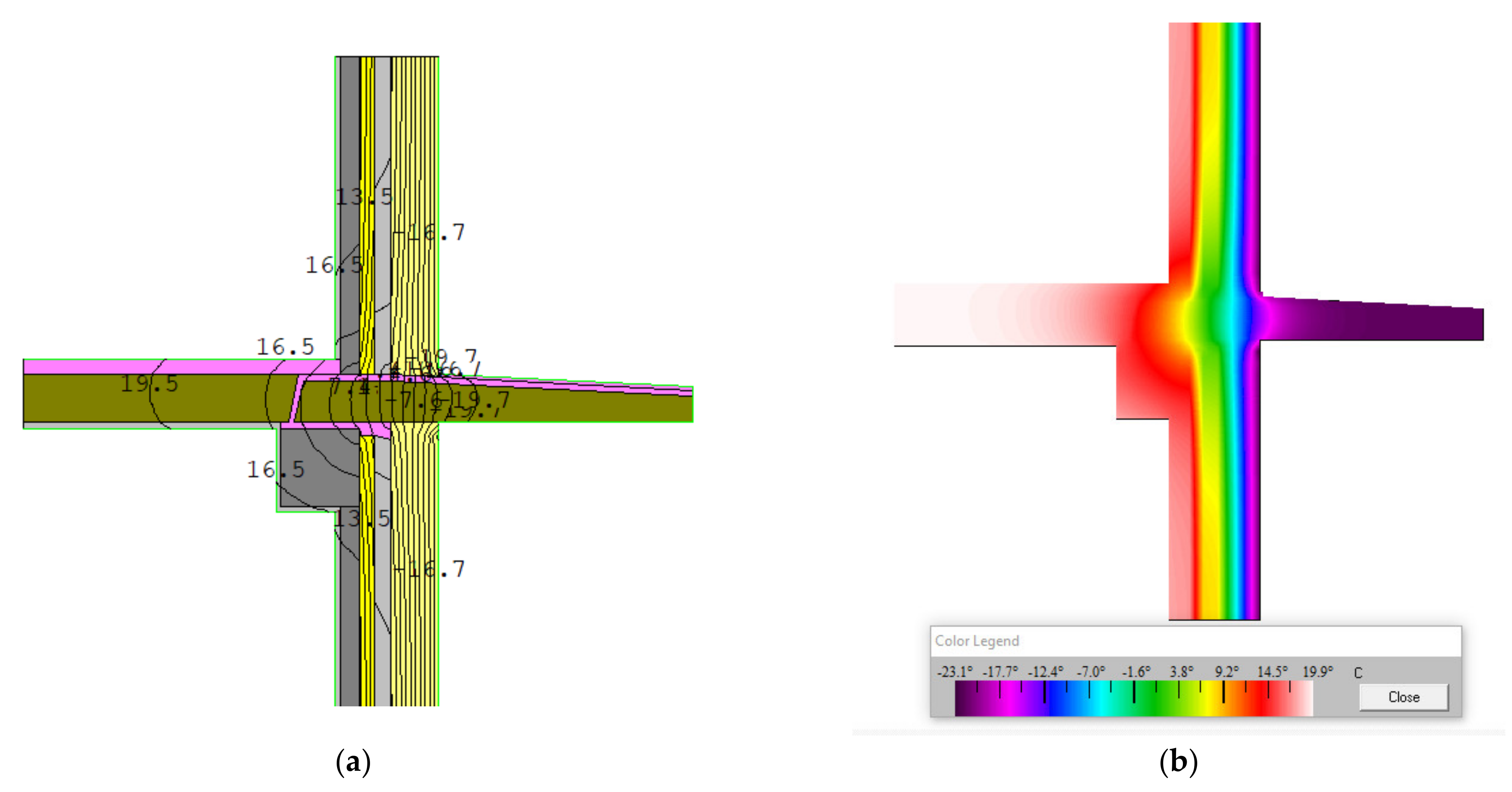
  • Connection of the wall (with EWI) and the uninsulated balcony slab—Figure 3a;
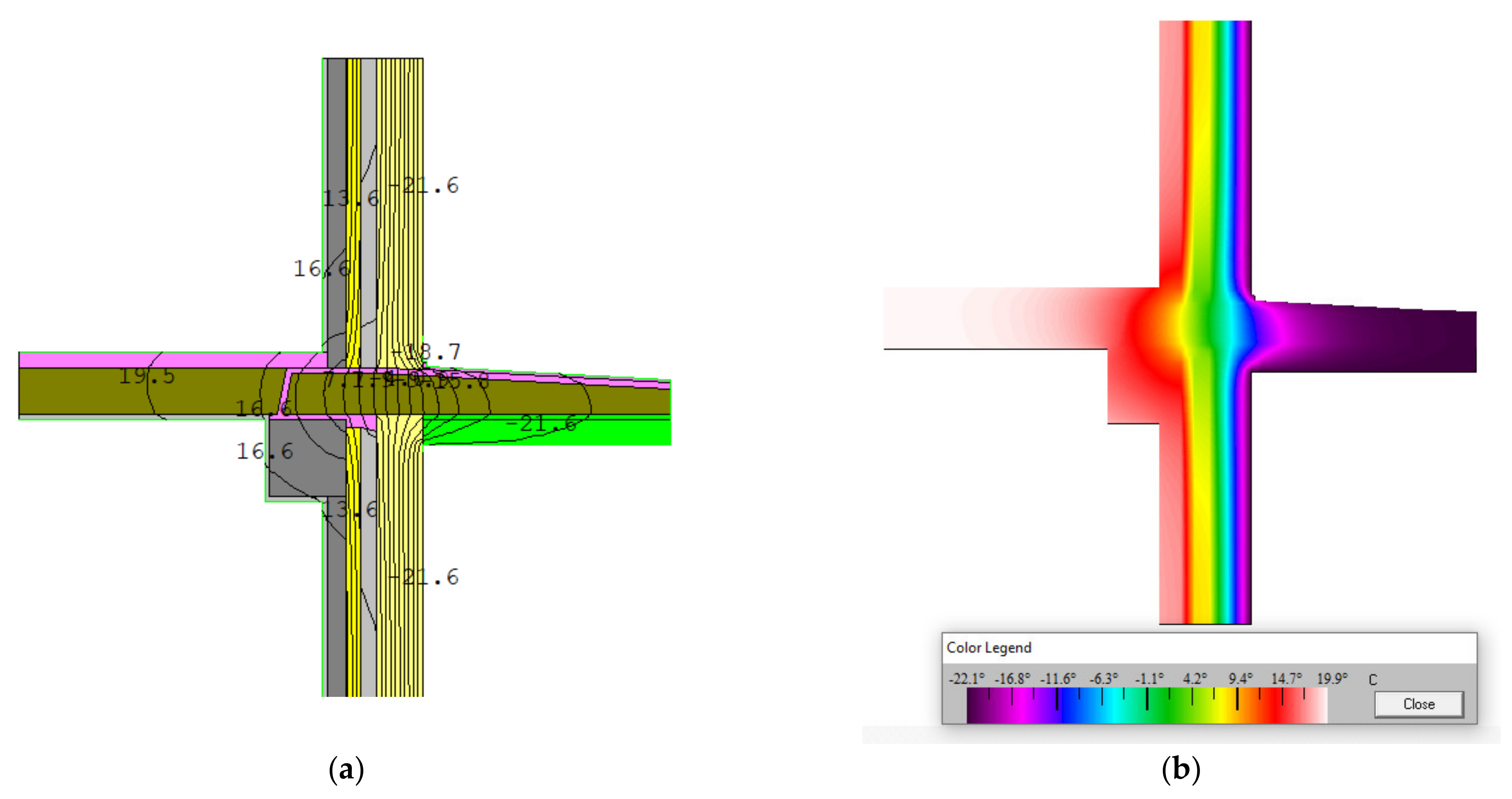
  • Connection of the wall (with EWI) with the insulated balcony slab (thermal insulation below the balcony slab)—Figure 3b;
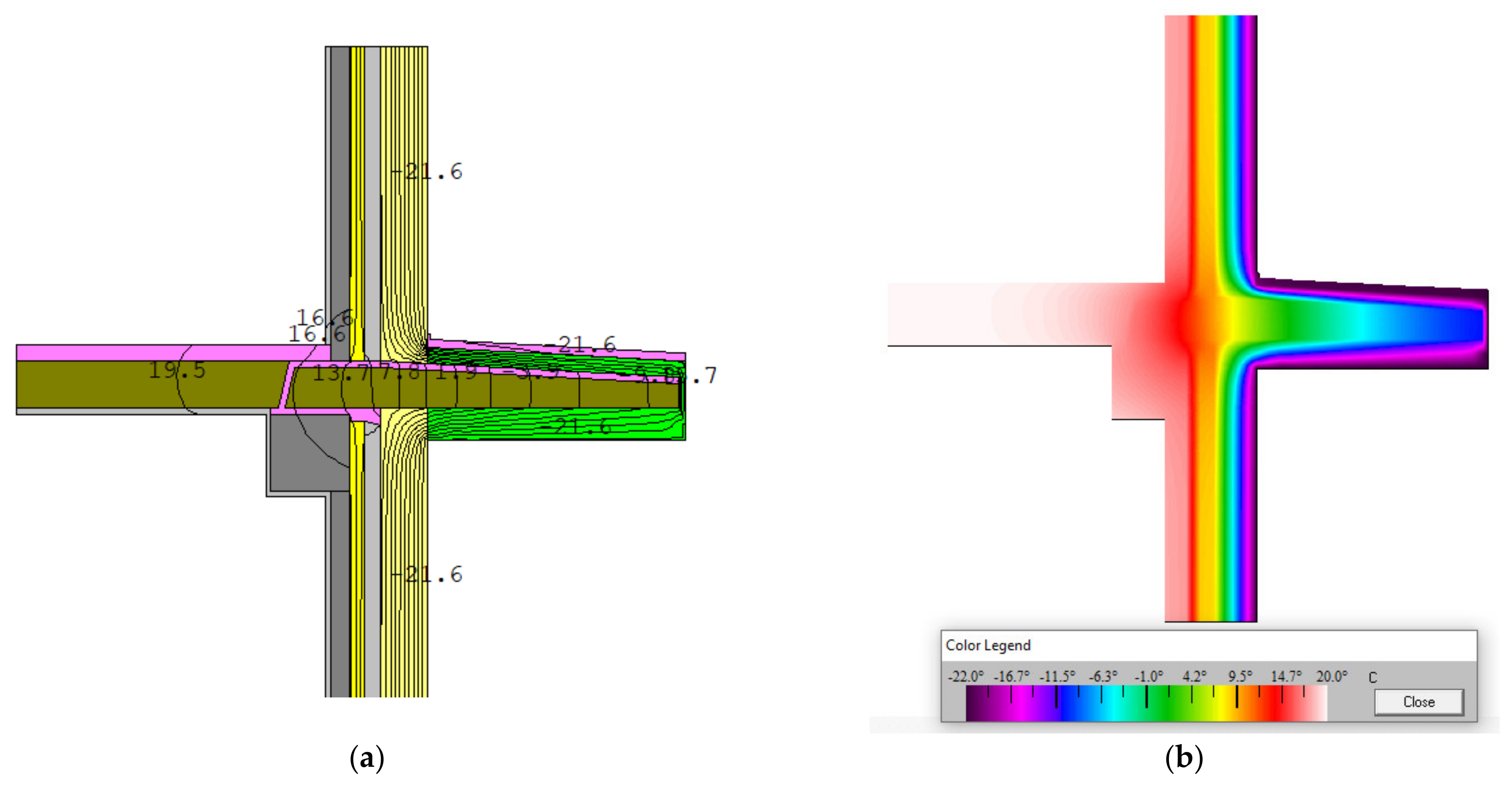
  • Connection of the wall (with EWI) with the insulated balcony slab (thermal insulation above and below the balcony slab)—Figure 3c;
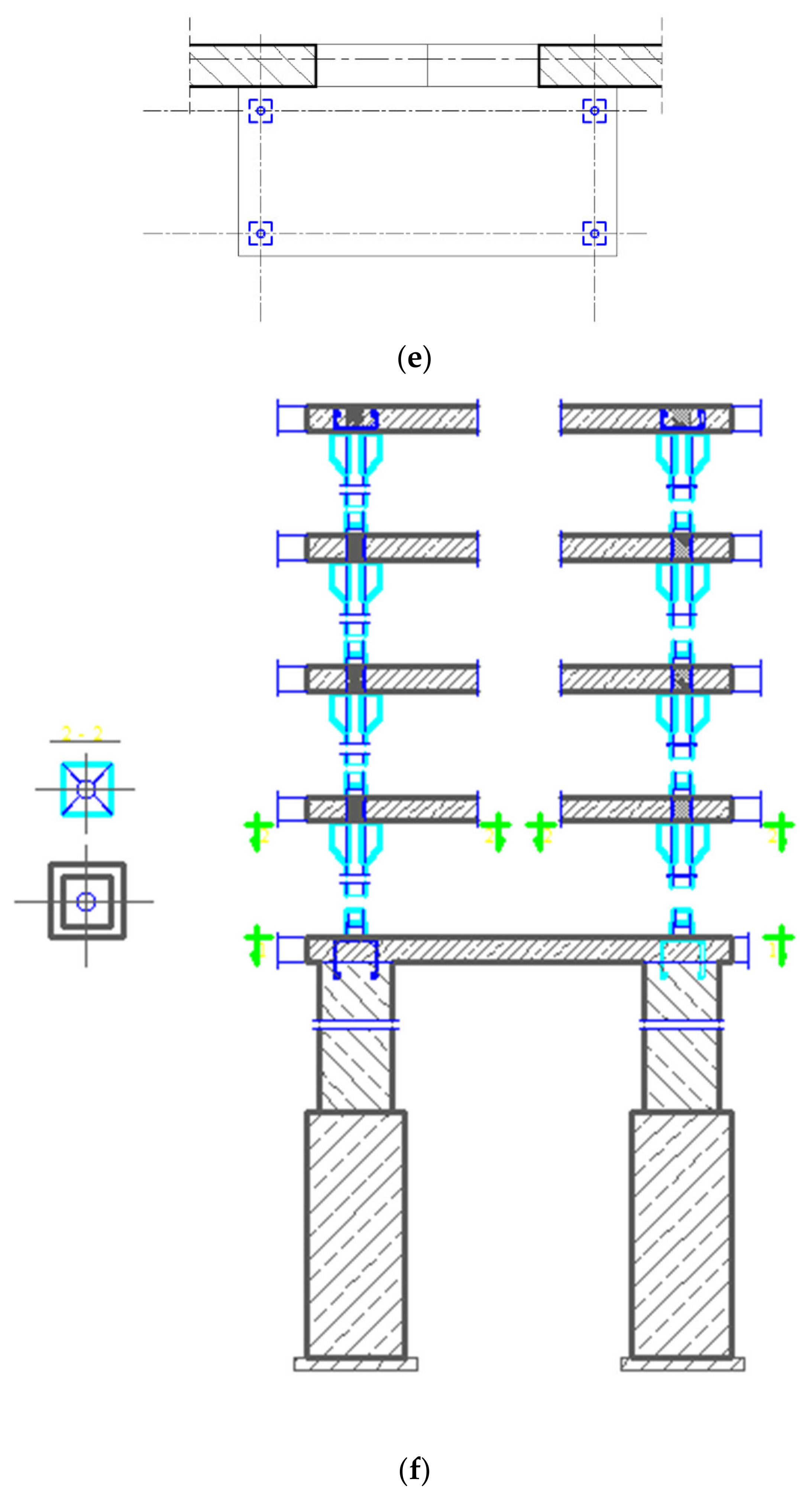
  • Alternative wall-to-balcony slab connection system: self-supporting outdoor added item, LKBD—Figure 3d–f.
The use of the structural thermal break was not considered due to the difficulties of applying such solutions in existing buildings.
In compliance with good building practice, balconies should be insulated as effectively as possible to limit the linear thermal bridge (scenario III—Figure 3c). Due to the desire to reduce costs and avoid complications of work, it happens that investors resign from insulating this element (scenario I—Figure 3a) or only insulate the balcony slab from the lower side (scenario II—Figure 3b). The reason for choosing scenario II may also be a recent renovation of the upper part of the balcony slab or the way of installing the balcony door (this is also the reason for the limited insulation thickness above the balcony slab in scenario III). In scenarios II and III, two insulating materials were considered: extruded polystyrene (XPS) with λ = 0.034 W/(m·K) and rigid resol foam (phenolic foam) with λ = 0.021 W/(m·K), with varying layer thicknesses (from 0.02 m to 0.10 m below the balcony slab and from 0.02 m to 0.05 m above balcony slab). The thickness and thermal properties of component materials are shown in Table 2.
The fourth scenario is an authors’ alternative solution based on the use of the structural system as in Figure 3d [38,39]. LKBD is characterized by a combined steel and reinforced concrete structure, largely independent of the building structure. It is performed after the existing balconies have been demolished. The new structure consists of steel columns, suitably ribbed under the balcony reinforced concrete slab (to form a support), supported in four points on the columns. Anchoring to the building structure ensures stability (it was assumed that six 20 mm diameter shear reinforcing bars passing through the EPS would be used in a 1.6 m width of slab).
Two different levels of the U-value of the wall were considered: 0.196 W/(m2·K) and 0.229 W/(m2·K). In the first case, the existing walls of large-panel buildings, with the structure as shown in Figure 3, were insulated with a 12 cm thick EPS layer. Although this thickness might seem not applicable today, it has been used in many retrofitted buildings and corresponds to thermal insulation requirements in the warmer climatic zones of southern European countries. In the second case, the layer of additional thermal insulation was 15 cm to meet the thermal insulation requirements for walls in Poland, in force from 31 December 2020 [30].
To compare the effectiveness of selected balcony slab modernization methods and to establish the solutions reducing the risk of surface condensation, the four scenarios illustrated in Figure 3 were thermally modelled. Then the selected solutions were applied on a real case study.

2.3. Assessing the Influence of the Balcony Slab Modernization Method on the Thermal Quality of the External Partitions and Design Heat Load of the Building

As mentioned previously, the modelling of the selected balcony connection details was carried out in accordance with the procedures of the standard [44], by using the THERM 6.3 software [45], developed by the Lawrence Berkeley National Laboratory (LBNL) in Berkeley, USA. THERM is a 2D finite element heat transfer programme, commonly used in the thermal evaluation of building partitions and construction joints [12,13,21,23,25,29,31,33,40]. The results are displayed in graphic form as isotherm and heat flux outlines, allowing for the visual evaluation of a thermal bridge. Information about the thermal transmittance coefficient (U-factor [W/(m2·K)]), averaged for the whole element, can be used for the further quantitative assessment of a joint. The linear thermal transmittance coefficient Ψ [W/(m·K)] of a thermal bridge is calculated according to the following Equation (1):
Ψ = L 2 D j = 1 N j   U j · l j ,
where L2D is the thermal coupling coefficient obtained from the 2-D calculations of the component separating the two environments being considered as a multiplication of the averaged thermal transmittance U-factor and the length of the modelled element [W/(m·K)]; Uj is the thermal transmittance coefficient of each building element j as it is estimated by 1-D calculation based on ISO 6946 [46] [W/(m2·K)]; [W/(m2·K)]; lj is the length within the 2-D geometrical model for which the value Uj applies [m]; Nj is the number of 1-D components.
The linear bridges are included in the calculation of the direct transmission transfer coefficient between the heated or cooled space and the exterior through the building envelope Hd [W/K] according to Equation (2) [47]:
H d = j A j · U j + k l k · Ψ k + i χ i ,
where Aj is the area of element j of the building envelope [m2]; lk is the length of the linear bridge k [m], Ψk is the linear thermal transmittance of the thermal bridge k [W/(m∙K)]; χi is the point thermal transmittance of point thermal bridge i [W/K].
The influence of thermal bridges on the thermal transmittance Umn [W/(m2·K)] of the building partition can be determined based on the Equation (3):
U m n = H d A i ,
where Umn is the mean thermal transmittance [W/(m2·K)] of the building fabric; Ai is the area of the element i of the thermal envelope not including the area to the adjacent building [m2].
The heat transfer across the thermal bridges Qtb [W] can be calculated by knowing the linear and/or point thermal transmittance of the thermal bridge as described in Equation (4). This can then be used to estimate the effect of the balcony slab modernization method on the peak heating load of the building.
Q t b = ( k l k · Ψ k + i χ i ) · θ i n t , i θ e ,
where θint,i is internal design temperature and θe is external design temperature.
Point thermal transmittance values, χ, can be determined precisely according to ISO 10211 [44] or, in some cases, by using the approximate procedure from ISO 6946 [46]. One such case is assessing the effect of mechanical fasteners penetrating an insulation layer. In this study, as in [25], stainless steel reinforcing bars were accounted for by modelling sections for scenario IV with and without the steel and taking the weighted averages of the U-values based on the steel size and spacing.

2.4. Standard Procedure for Determining the Risk of Mould Growth

Properly constructed partitions and their joints in the building envelope should exclude the risk of mould growth on their internal surfaces in the designed operating conditions of the building. The condition of surface condensation occurrence was checked based on the ISO 13788 standard [48]. The evaluated parameter is the temperature factor (fRsi), calculated as shown in Equation (5), by taking the difference between the internal surface temperature and external temperature (θsiθe), and dividing it by the difference between internal temperature and external temperature (θiθe). The fRsi is, therefore, a dimensionless parameter. Internal surfaces, where the risk of mould growth and surface condensation occurs, are those which fall below the design temperature factor, fRsi,max, appointed for the critical month (which is the month with the highest fRsi,min value, determined for a use class of building).
f R s i = θ s i θ e θ i θ e f R s i , m a x = θ s i , m i n θ e θ i θ e ,
The application of the method according to [48] requires climatic data concerning the monthly mean external temperature and relative humidity. Therefore, the maximum (critical) value of the fRsi is a variable value depending on the location of the analyzed building. The governments of individual countries set the indicative value of the critical temperature in their building regulations. In Poland, in rooms heated to a temperature of at least 20 °C in residential buildings, housing and public buildings, assuming the monthly average value of indoor air relative humidity of 50%, the required critical temperature factor is 0.72 [30].
In the second stage of this research, the temperature distribution was determined in all analyzed scenarios of connecting the walls with the balcony slab, using the THERM programme. The calculated temperature factor was compared with the critical values determined by two methods (detailed and simplified).

2.5. Methodology for Assessment of the Cost Effectiveness of Investments

A static method was used to assess cost-effectiveness. It excludes the question of changes in the value of money over time, but it is sufficient to compare different retrofit options. The Simple Payback Time SPBT (years) was calculated according to Equation (6). To determine annual savings in energy costs resulting from the implementation of the thermo-modernization improvement ΔOrU [€/year], the regulation on preparing energy audits in Poland [49] was used. The variable fee with distribution and transmission of energy unit Oz [€/GJ] was considered, without fixed and subscription fees.
S P B T = N u Δ O r U = N u Δ Q u · O z = N u 8 , 64 · 10 5 · S d · A i / Δ R · O 0 z ,
where Nu are the inputs needed to carry out the investment [€]; ΔOu is reduction of the annual heat demand to cover heat transmission losses as a result of the modernization project (GJ); Sd is number of degree days of the heating season (days∙K/year); Ai is the area of the wall (m2); ΔR is the difference of the total thermal resistance of the assessed wall ((m2∙K)/W).

2.6. Description of the Assumptions Used in the Calculations

The principles of modelling thermal bridges and setting boundary conditions were adopted in accordance with the applicable standards [44,46,48]. Considered interventions on precast cantilever balconies and features of materials used in the scenarios considered are reported in Section 2.2. As the calculation procedure according to ISO 10211 [44] requires modelling the element in such a way that it is extended at least 1 m or a triple thickness of the element away from the geometrical centre of the thermal bridge (to restore one-dimensional heat flow at the cut-off plane), in the described cases:
  • the floor slab was continued for 1 m inside of the building (the vertical face of the slab on the interior was specified as an adiabatic surface);
  • the walls were continued for 1 m beyond floor slab (the horizontal faces of the walls were specified as an adiabatic surfaces);
  • each scenario was modelled with a balcony slab length of 1.8 m on the exterior.
An internal temperature of 20 °C and an external temperature of −22 °C were defined in the heat loss simulations. The external temperature corresponded to the location of the buildings used as case studies (IV climatic zone of Poland). Additionally, the location of buildings in four other climate zones of Poland was analyzed. Climatic data for five selected cities in each of the five climatic zones of Poland are presented in Table 3.
The surface resistances to determine U-values of walls and thermal bridging heat loss were set in accordance with ISO 6946 [46]: Rse = 0.04 (m2·K)/W), therefore, the exterior heat transfer coefficient was 25 W/m2 K; Rsi = 0.13 (m2·K)/W), therefore, the interior–exterior heat transfer coefficient was 7.692 W/m2 K. The increased surface thermal resistance at the internal surface, (Rsi = 0.25 (m2·K)/W)), for determining minimum internal surface temperatures and, hence, temperature factor according to standards [44,47] was used. The external dimensions of the building elements were used to calculate heat transfer, both through the building envelope and through thermal bridges

3. Results and Discussion

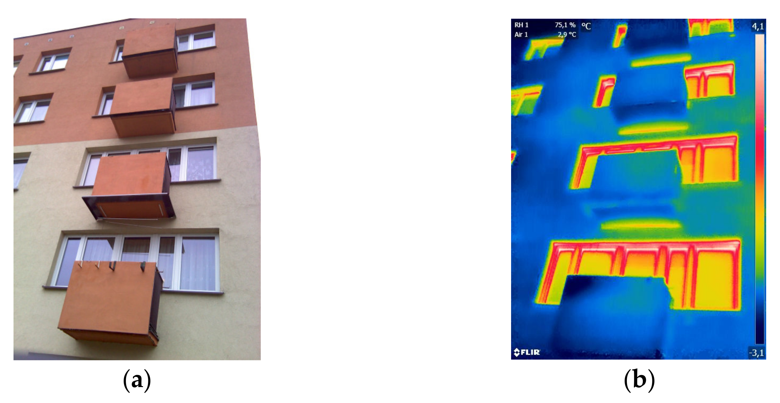
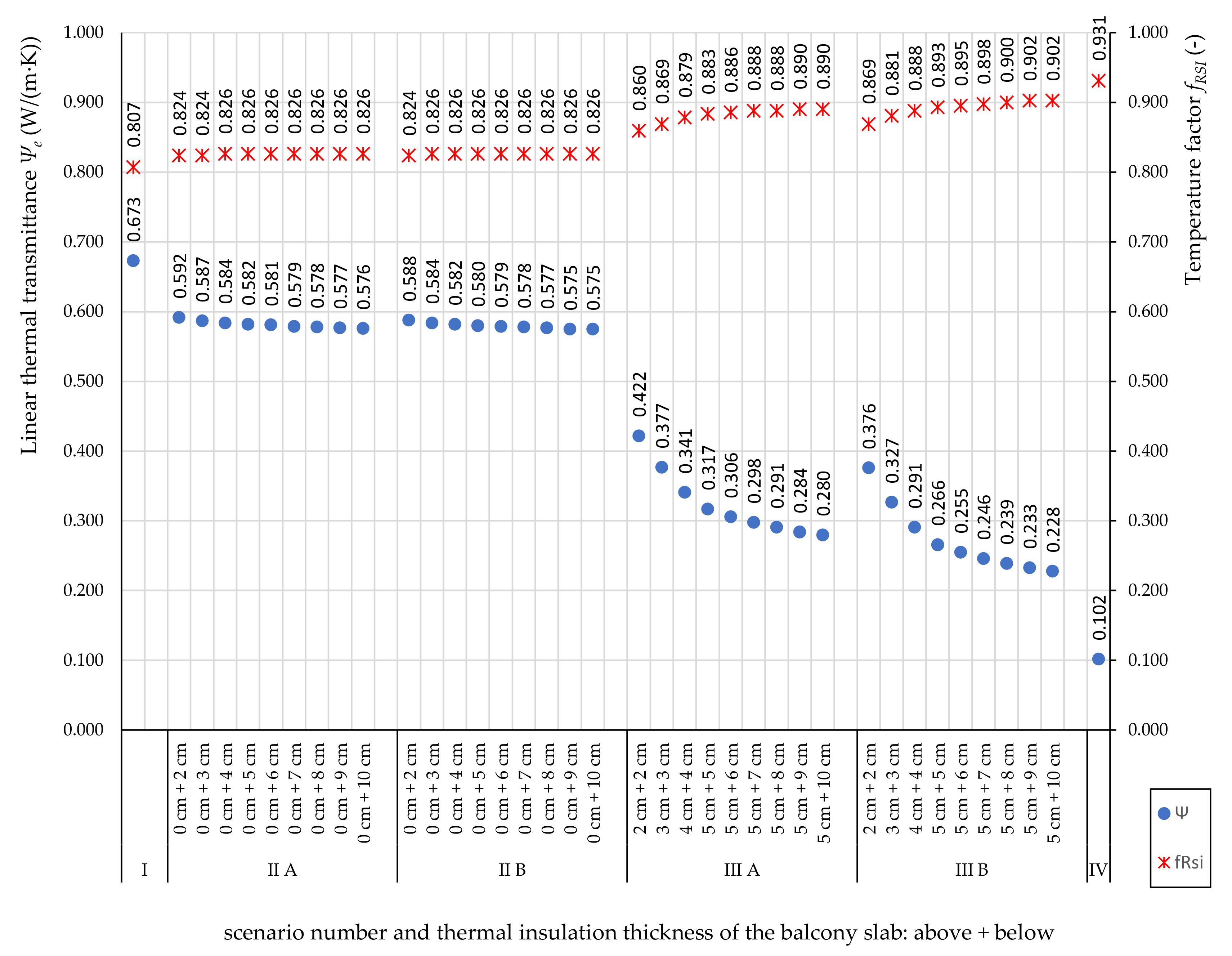
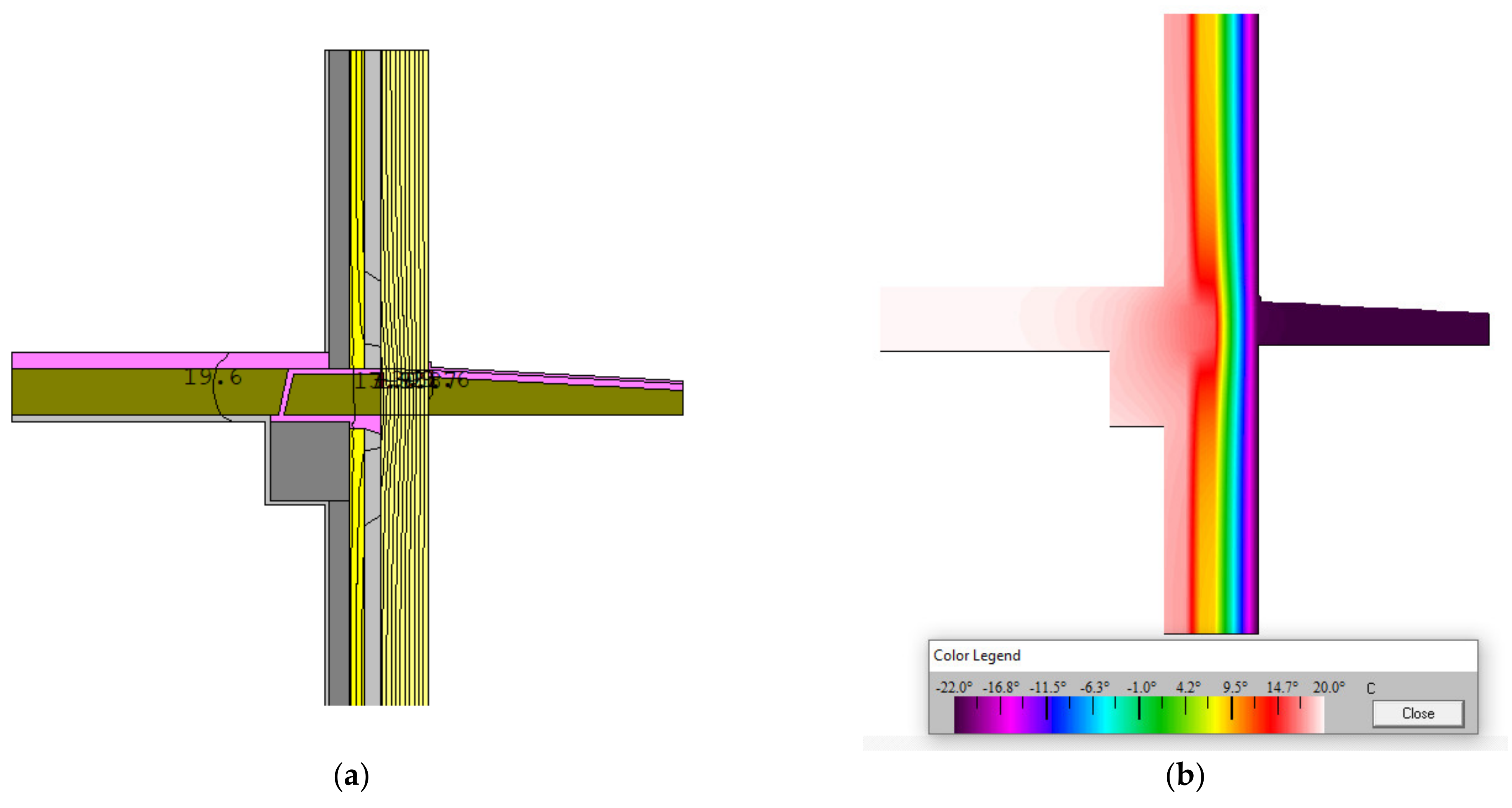
3.1. Heat and Humidity Analysis of Balcony Thermal Bridges

The simulation of the interventions on precast cantilever balconies using THERM allowed us to prove the advantages of using the light balcony system and modern insulation materials compared to other traditional solutions analyzed. Figure 4 and Figure 5 present the linear thermal transmittance as well as the temperature factor of all considered scenarios and the temperature factor at the real location of the building (near Bialystok). Figure 4 applies to the case when the walls of a large-panel building have been insulated with an additional 12 cm thick thermal insulation. Uwall = 0.229 W/(m2·K) does not meet the requirements currently in force in Poland but is often found in buildings that have been modernized in recent years. Figure 5 concerns a wall with additional 15 cm thick thermal insulation, which meets the current requirements in Poland (Uwall = 0.196 W/(m2·K) < Uwall,max = 0.20 W/(m2·K) [30]).
The study first assessed the linear thermal transmittance of the thermal bridges in the building. The Ψ values of the same balcony slab retrofit solutions for a wall with better thermal insulation (Uwall = 0.196 W/(m2K) were in most cases lower than for a wall with poorer thermal insulation (Uwall = 0.229 W/(m2K)). In the case of scenario I, this difference amounted to 5.35%; in scenario II from 4.17–4.50%; in scenario III from 0.34–2.39%; in scenario IV by 10.78%. Such a difference was not noted for the largest considered thicknesses of the insulation material of the balcony slab insulated around with resol foam (8, 9, and 10 cm from the bottom of the slab +5 cm from the top of the slab, in scenario IIIB).
The results presented in Figure 4 and Figure 5 show how the linear thermal transmittance decreased using all the methods of insulating cantilevered balconies considered. In this sense, scenario IV was the one which obtained the lowest linear thermal transmittance and a decrease of 84.84% (for a wall with 12 cm thick insulation) and 85.71% (for a wall with 15 cm thick insulation) with respect to the solution with the uninsulated balcony slab scenario I). The other solutions obtained lower improvements than LKBD (the self-supporting outdoor added item): scenario IIA achieved a decrease of between 12.04 and 14.41% (for a wall with 12 cm thick insulation) and from 11.15–13.34% (for a wall with 15 cm thick insulation) with respect to scenario I; scenario IIB achieved a decrease from 12.63–14.56% and 11.77–14.66%, respectively; scenario IIIA achieved a decrease from 37.30–58.40% and 35.16–56.51%, respectively; IIIB achieved a decrease from 44.13–66.12% and 41.92–64,21%, respectively, being the scenario with the second-best results.
In terms of the linear heat transfer coefficient, the LKBD system proved to be over 5 times better for the solution consisting of the thermal insulation of balcony slabs from the bottom and more than 2 times better than the cases with top and bottom insulation.
When assessing the determined values of Ψ in the light of the classification of thermal bridges according to the Building Research Institute [32], it can be concluded that the solutions from scenarios I, IIA, IIB cause bridges with a very high impact, and solutions from scenario IIIA and most of the bridges from scenario IIIB—bridges with high impact. Thermal insulation of balcony slabs all around with 5 cm of insulation from the top and more than 6 cm from the bottom of the slab, as well as the LKBD system in the wall with 12 cm thick insulation, result in low-impact thermal bridges. Additionally, the use of the LKBD system in a wall with 15 cm thick insulation, which corresponds to the current requirements in Poland [30], results in a bridge with negligible impact.
Comparing the determined linear thermal conductivity of the tested balcony bridges with the literature data on the use of thermal breaks (0.18 W/(m∙K) [29] or 0.15 W/(m∙K) [27,28]), it can be concluded that only option better than them is the LKBD system.
Figure 4 and Figure 5 present not only the Ψ value for each scenario, but also the ƒRsi. The determined values of the temperature factor, according to Equation (5), correspond to the minimum temperatures in the connections between the balcony slab and the wall. Sample THERM models generated using the solutions presented in Figure 3 are shown in Figure 6, Figure 7, Figure 8 and Figure 9.
Then, the obtained values of the temperature factor for further variants of the calculation were compared with the critical values to assess the risk of surface condensation. The critical temperature factor for five selected cities in each of the five climatic zones of Poland, determined using the Audytor OZC 6.9Pro software (produced by SANKOM in Warsaw, Poland), is presented in Table 4.
For each of the analyzed locations in Poland, the critical temperature value calculated according to the standard procedure [48] was higher (from 9.86–18.47%) than the indicative value specified in the building regulations [30]. Therefore, the method according to the ISO 13788 standard [48] was used to assess the risk of moisture in the analyzed joints.
Analyzing the results presented in Figure 4 and Figure 5 (for the location in Bialystok), it was proven that in the case of using both a balcony slab without insulation (scenario I) and an insulated balcony slab on the bottom (scenario II), the code condition to avoid surface condensation of water vapor is not met. In the case of thermal insulation of the balcony slab from below and from above using XPS (scenario IIIA), the obtained value of the temperature coefficient is higher than the critical value from 2.08–5.76% (for a wall with 12 cm thick insulation) and 3.21–6.61% (for walls with 15 cm insulation). In the case of using resol foam around the balcony slab (scenario IIIB), the obtained differences amounted between 3.21 and 7.17% and 4.34 and 8.02%, respectively, while using the LKBD system (scenario IV) was between10.61% and 11.43%. Scenario IV achieves the lowest Ψ-value so is deemed to be the most successful. The application of the LKBD system also allows for avoiding the risk of surface condensation of water vapor in the joints of the balcony slabs with the walls (the obtained ƒRsi is higher than the critical value) under appropriate operating conditions (adequate air humidity and efficient ventilation). While in air-tight, higher-humidity buildings, with insufficient ventilation (which is often observed in retrofitted buildings), it can form condensation on “cold” indoor surfaces, causing mould to grow.

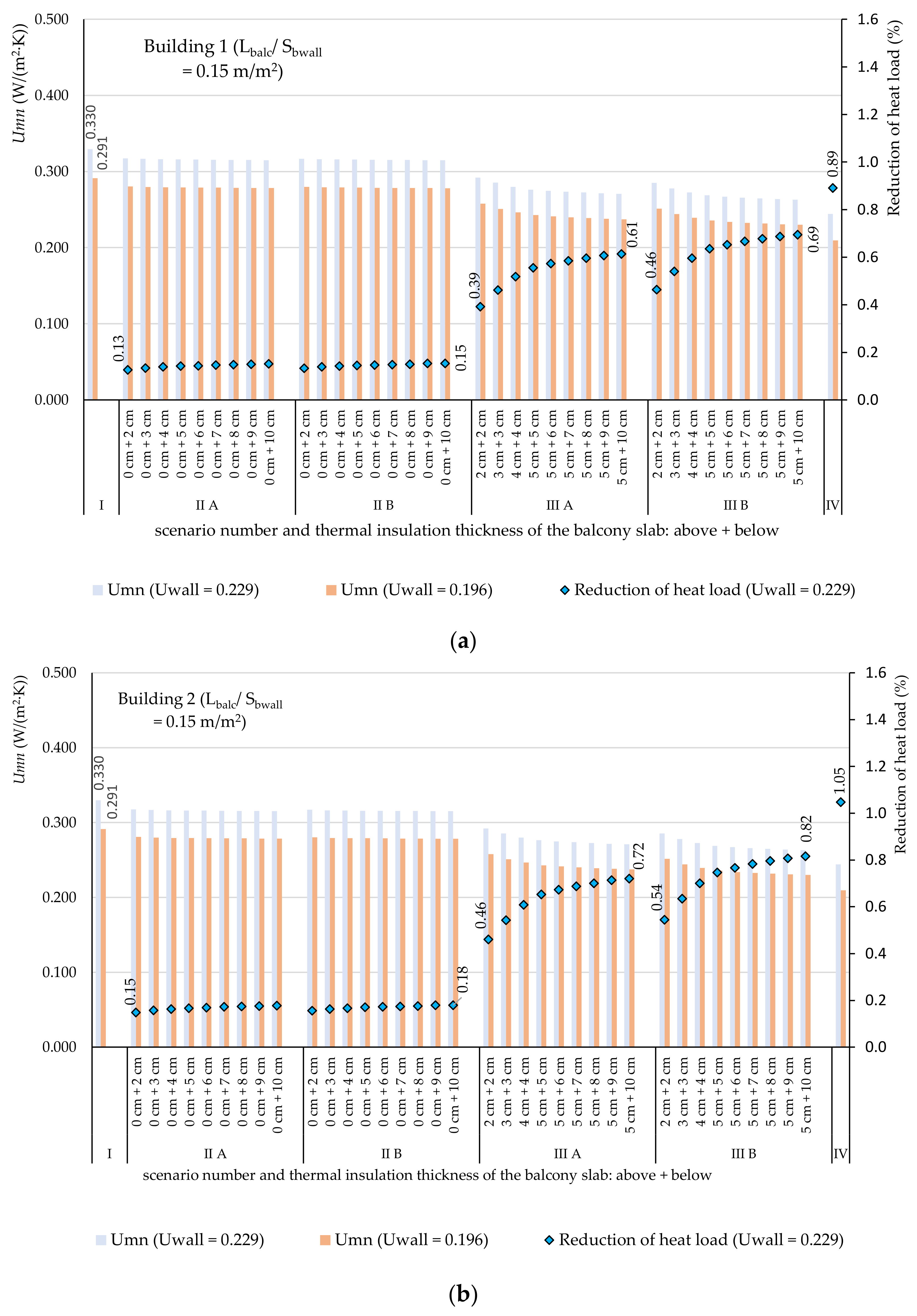
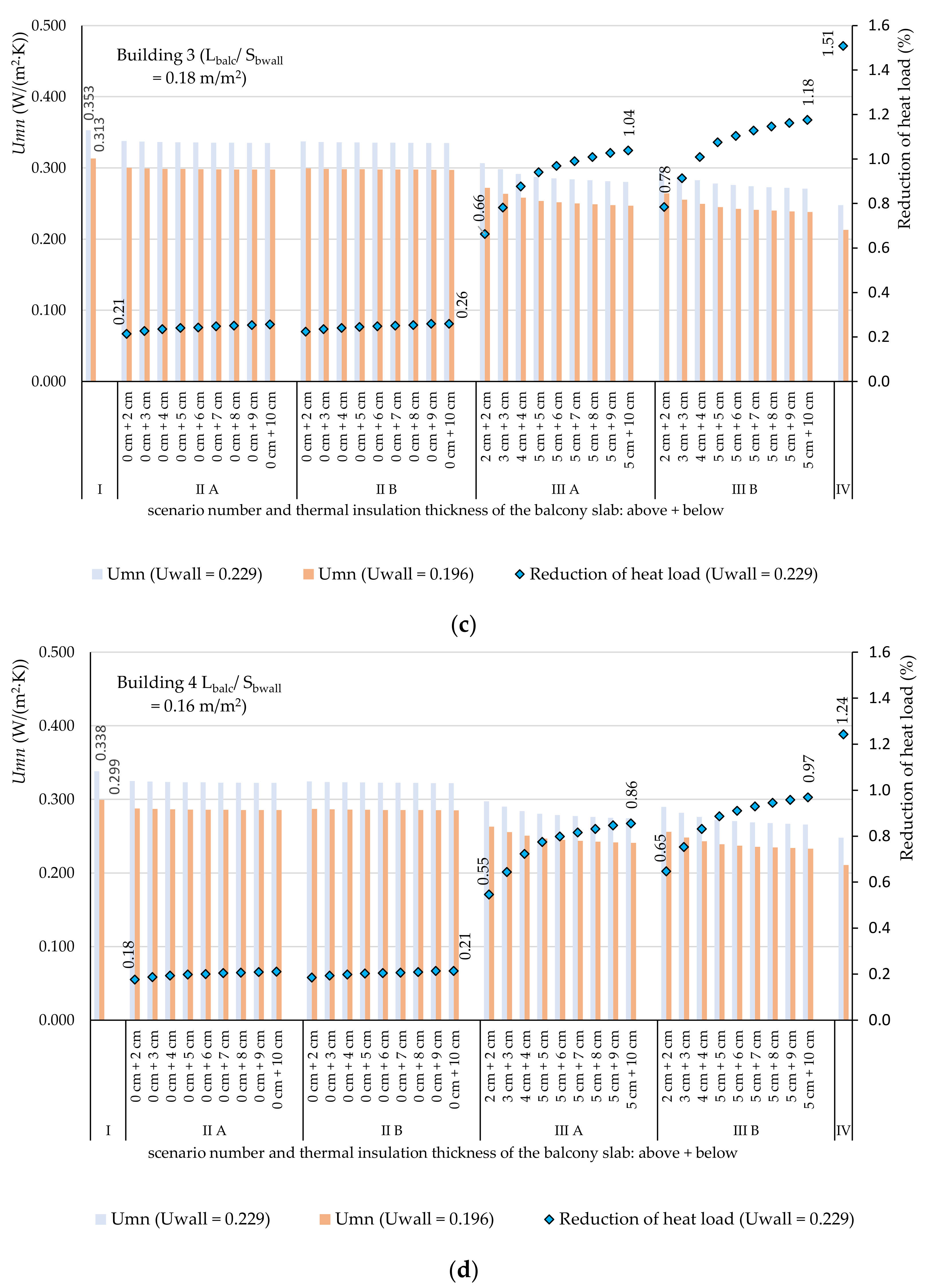
3.2. Possibility of Heat Loss Reduction in Example Multi-Family Buildings

The linear thermal transmittance coefficients determined in Section 3.1 were used to test the effectiveness of individual balcony modernization methods on the scale of the entire building. As a case study, four multi-family apartment blocks were analyzed, described in 2.1. The nature of the impact of thermal bridges on the thermal transmittance of building walls, determined based on Equation (3), is shown in Figure 10.
Uninsulated balcony slabs had the greatest impact on the deterioration of the wall insulation. The increase in the U-value of the walls in the analyzed buildings amounted to between 44 and 54% (in the case of a 12 cm thick EPS insulated wall) and between 49 and 60% (in the case of a 15 cm thick EPS insulated wall). In scenario II, the increase was slightly lower and amounted to approximately between 38 and 48% and between 43 and 53%, respectively. Insulating the balcony slabs from above and below was a much better solution. Here, the increase in the U coefficient of the walls reached between 18 and 33% and between 21 and 39% (with the use of XPS) and between 15 and 30% and between 17 and 35% (with the use of rigid resol foam). The best solution was to implement LKBD where Umn was from 7–8% higher than the U-value of the wall without thermal bridges.
Figure 10 also shows the calculated possibility of reducing the designed heat load of individually analyzed buildings (using Equation (4) and the actual data for buildings presented in Table 1). The determination of these savings was possible only for the versions of buildings with 12 cm thick polystyrene wall insulation, as this is how the case study buildings were insulated. When LKBD is used, it is possible to reduce the design heat load from 0.89–1.51% compared to buildings with balcony slabs without insulation (Figure 10). For other scenarios, the reduction is even smaller: with thermal insulation of the balcony slabs from below and above, the reduction ranges from 0.39% to 1.18%, and for insulation only from the bottom, less than 0.26%. The reduction of heat losses through the building envelope, and thus, the reduction of heat load and heat consumption, results in lower heating bills for the building. These savings will also depend on the type of heat source and the unit energy price. The economic analysis for the cases considered in the article is provided in Section 3.3.

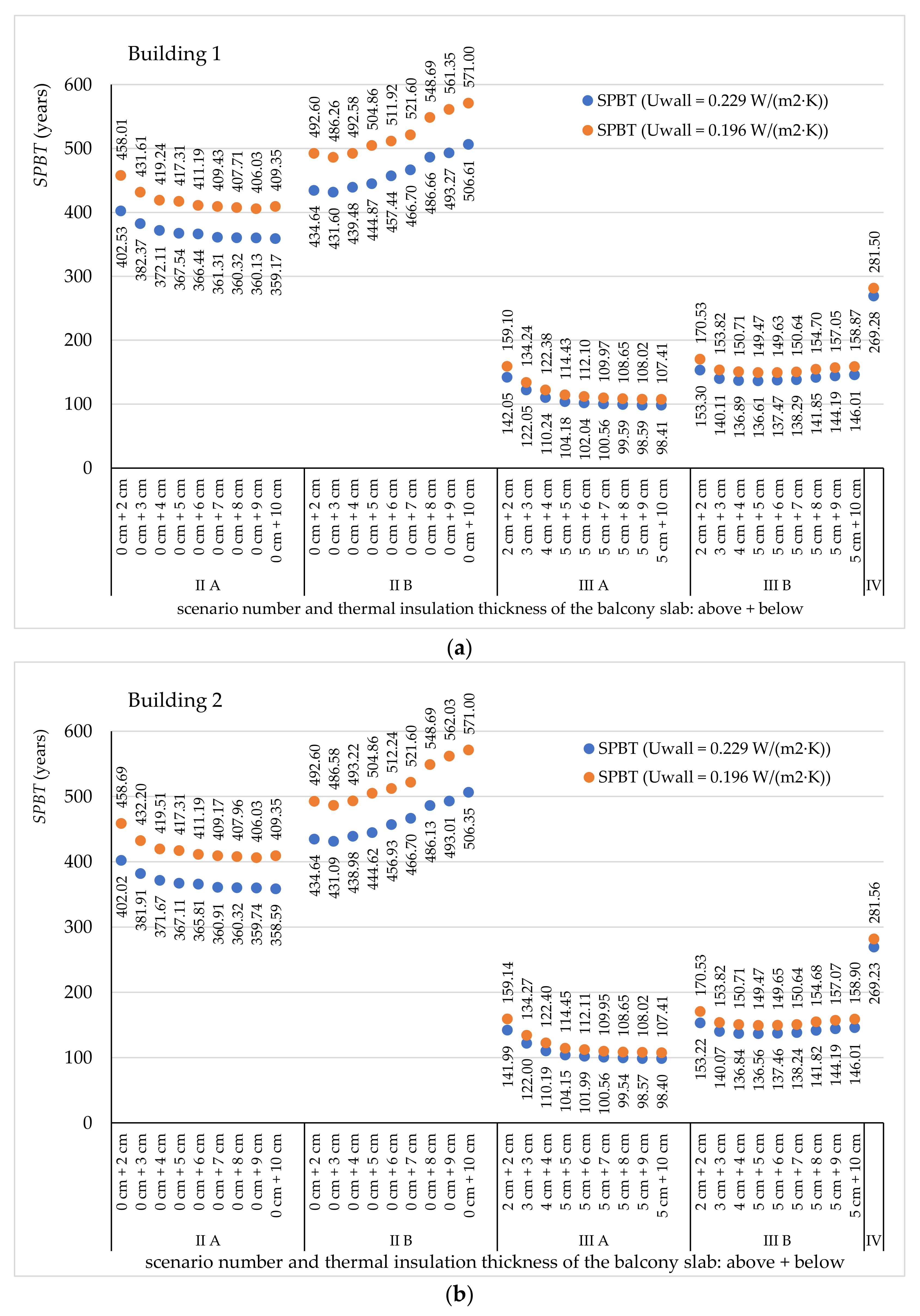
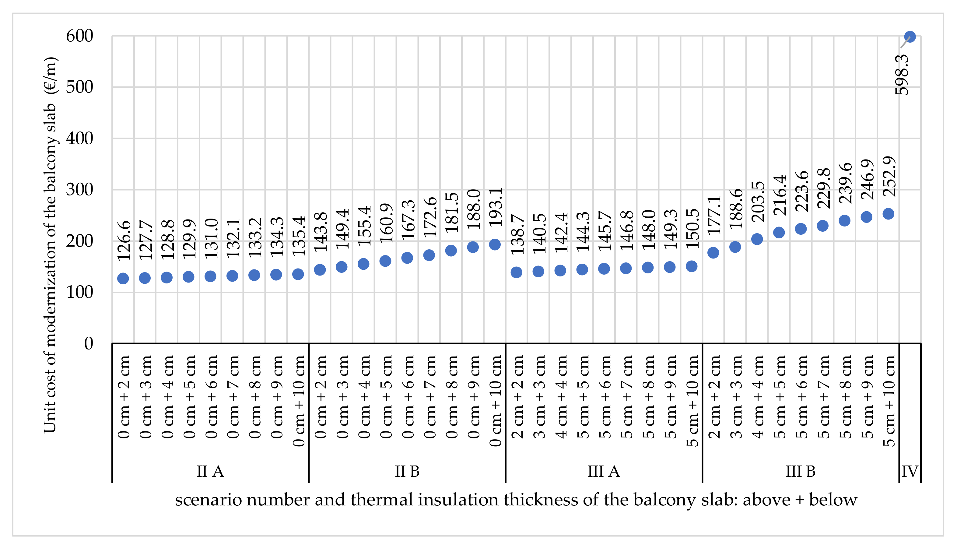
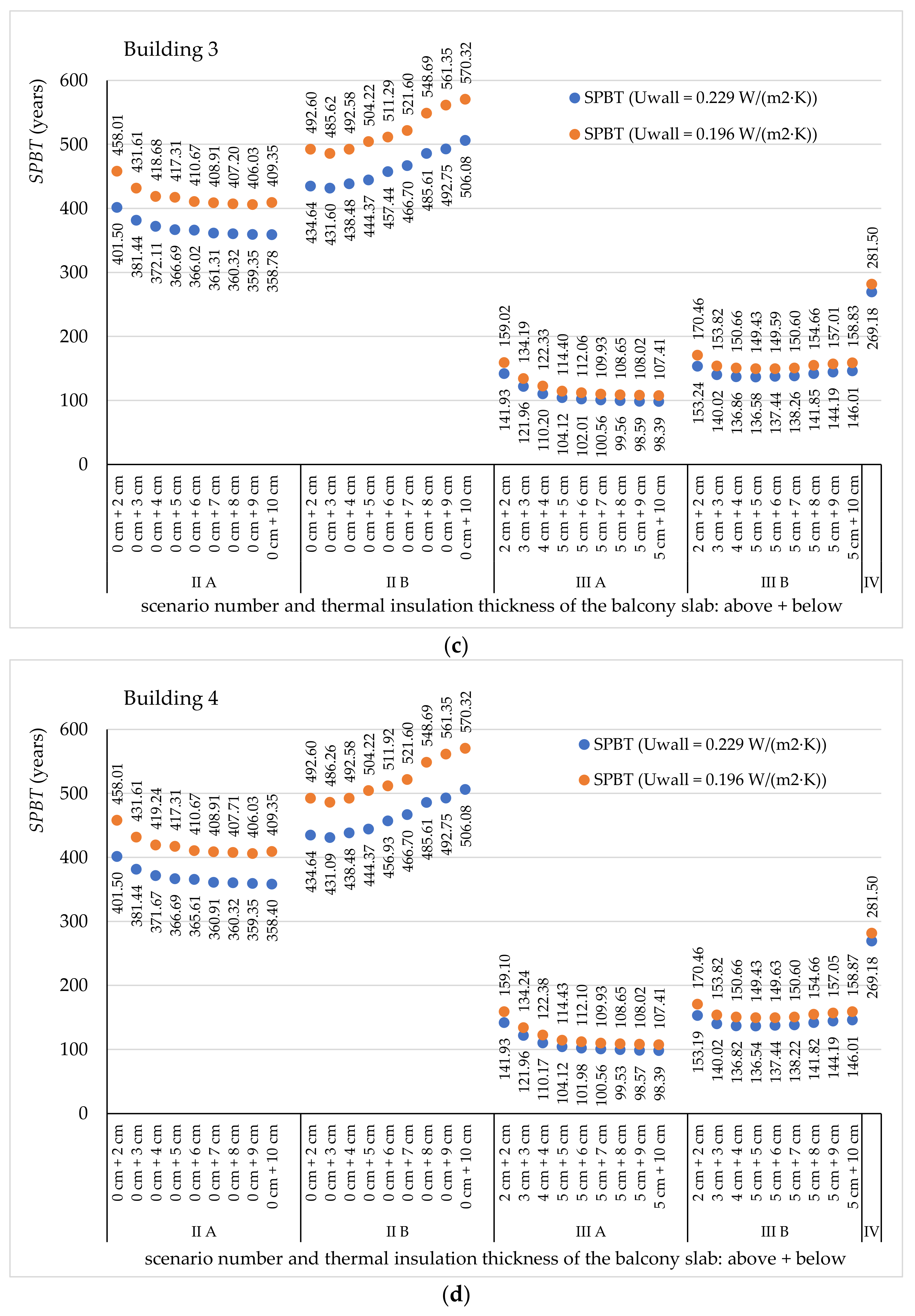
3.3. Economic Analysis

For each of the considered scenarios, the inputs needed to implement the modernization investment was determined. The amounts of individual cost components are summarized in Table 5. In scenarios II and III it was assumed that the balconies are not damaged from the structural point of view. Therefore, the costs related to their thermal modernization and restoration of finishing layers were considered.
By far the most expensive solution is to use LKBD. The cost of the entire riser for new balconies added in a five-story building is 2.37 times higher than the most expensive method of thermal insulation (in scenario IIIB). The use of modern building materials in scenario III (rigid resol foam, phenolic foam) instead of traditional (extruded polystyrene) increases the costs of the same solutions from 28–68%. Scenario II was not subjected to a thorough cost analysis because, as shown in Section 3.1, it should not be used due to the risk of surface condensation.
High investment costs may be a barrier to the use of modern materials and solutions in construction practice. Figure 11 shows the cost of individual methods of modernization of balcony slabs in relation to the 1 m length of balconies. Such information may be useful for energy audits, architects, or civil engineers. It is worth emphasizing that the correct solution from the point of view of humidity scenario IIIA is cheaper by between 5.1 and 42.6% than scenario IIB, which may cause surface condensation.
To evaluate the cost effectiveness of the investment according to the adopted method (SPBT), the average price of a unit of energy was assumed at the level of 11 €/GJ [51]. The Simple Payback Time, calculated according to Equation (6), is shown in Figure 12.
In all analyzed buildings, by far the highest SPBT (>359 years) was obtained for investments related to the thermal insulation of balcony slabs from below (scenario II). Additionally, as mentioned earlier, such a solution carries the risk of surface condensation, so it should not be used.
The most cost-effective renovation method is to insulate the balcony slabs from below and above with the thickest possible XPS layer (SPBT = 98.4–107.4years). Replacing XPS with modern material increases SPBT by almost 50%, for the LKBD system, SPBT = 269.2–281.5 years. More favorable energy and economic effects related to the reduction of balcony thermal bridges were achieved in the wall with lower insulation. The obtained values of the SPBT index are very high and significantly exceed the lifetime of the analyzed building elements; therefore, they cannot be considered economically effective. The article specifies the SPBT index to compare the various analyzed scenarios. The justification for the need to modernize balconies in the retrofitted multi-family buildings is not energy or economic, but functional reasons (limiting the potential condensation of moisture at the junction of the balcony slabs of the buildings with the walls).

4. Conclusions

In this study, it is shown that the application of modern insulation materials and new technical solutions in buildings can be very beneficial for utility reasons, even if the provided economic data does not seem to be very stimulating. The conducted analyses showed that leaving the balcony slabs without insulation or only insulating them from the bottom, which is often applied in practice, carries the risk of surface condensation. Therefore, such solutions should not be used and there is a need to look for modern solutions in buildings. It has been shown that the justification for the need to modernize balconies in retrofitted multi-family buildings is not energy or economic, but functional (limiting the potential condensation of moisture at the junction of balcony slabs of buildings with walls).
This article presents the advantages and disadvantages of the use of modern insulation materials and the new LKBD system, which have not been available in the literature so far, compared to other methods of balcony renovation.
The most cost-effective method of renovation, while avoiding the risk of surface condensation, proved to be the insulation of the balcony slabs from the bottom and from the top. When using XPS, the payback time at current costs is between 98.4 and 142 years. Replacing polystyrene with a modern insulation material (resol foam) increased the SPBT to between 107.4 and 159.1 years; however, it remained the scenario with the second-best result. The use of an appropriate thickness of the insulating material in the form of resol foam (7–10 cm from the bottom and 5 cm from the top of the slab) allows for classifying the existing thermal bridges to the low-impact group (Ψe < 0.25 W/(m·K)).
The advantage of using LKBD, which also avoids surface condensation, is a very low linear heat transfer coefficient. A wall that meets the current requirements in Poland (U = 0196 W/(m2∙K) Ψe = 0.091 W/(m∙K)) classifies this solution as thermal bridges with negligible impact. It is also a better solution in this respect (even almost twice) than the construction of balconies with thermal breaks. Unfortunately, the SPBT of such a project is very long (281.5 years) and this may be the reason why this type of structure is rarely used in retrofitted buildings.
Despite the relatively small impact (up to 1.51%) of the analyzed scenarios of the modernization of balcony slabs on the designed thermal load of entire buildings, the considered examples indicate the need to perform thermal, economic and moisture calculations to indicate the most beneficial solutions and eliminate incorrect ones.
Modern materials and solutions are characterized by better parameters than traditional solutions, but due to their high cost, their profitability is not high and require financial support to be more commonly used in construction practice.
For future research, a multi-criteria analysis of the design solutions presented in this paper is planned. It would also be interesting to carry out a cost analysis covering only the thermal insulation (treating the other building work as renovation).

Author Contributions

Conceptualization, B.S. and P.B.; methodology, B.S.; software, B.S.; formal analysis, B.S. and P.B.; investigation, B.S. and P.B.; resources, B.S. and P.B.; writing—original draft preparation, B.S. and P.B.; writing—review and editing, B.S.; visualization, B.S. and P.B.; funding acquisition, B.S. All authors have read and agreed to the published version of the manuscript.

Funding

This work was performed within the framework of the grant from the Bialystok University of Technology WZ/WB-IIL/5/2019 and financed by the Ministry of Science and Higher Education of the Republic of Poland.

Institutional Review Board Statement

Not applicable.

Informed Consent Statement

Not applicable.

Data Availability Statement

Data is contained within the article.

Conflicts of Interest

The authors declare no conflict of interest.

References

  1. United Nations Environment Programme. 2020 Global Status Report for Buildings and Construction: Towards a Zero-emission, Efficient and Resilient Buildings and Construction Sector; Nairobi, Kenya. 2020. Available online: www.globalabc.org (accessed on 14 January 2021).
  2. Global Alliance for Buildings and Construction; International Energy Agency; The United Nations Environment Programme. 2019 Global Status Report for Buildings and Construction: Towards a Zero-emission, Efficient and Resilient Buildings and Construction. Available online: https://www.iea.org/reports/global-status-report-for-buildings-and-construction-2019 (accessed on 14 January 2021).
  3. European Commission. A Clean Planet for all A European Strategic Long-Term Vision for a Prosperous, Modern, Competitive and Climate Neutral Economy. 2018. Available online: https://eur-lex.europa.eu/legal-content/EN/TXT/PDF/?uri=CELEX:52018DC0773&from=EN (accessed on 14 January 2021).
  4. Directive (EU) 2018/844 of The European Parliament and of the Council of 30 May 2018 amending Directive 2010/31/EU on the energy performance of buildings and Directive 2012/27/EU on energy efficiency. Available online: https://eur-lex.europa.eu/legal-content/EN/TXT/?uri=uriserv%3AOJ.L_.2018.156.01.0075.01.ENG (accessed on 14 January 2021).
  5. European Commission. A Renovation Wave for Europe—Greening our Buildings, Creating Jobs, Improving Lives; Brussels, Belgium. 2018. Available online: https://ec.europa.eu/energy/sites/ener/files/eu_renovation_wave_strategy.pdf (accessed on 14 January 2021).
  6. Filippidou, F.; Jimenez Navarro, J.P. Achieving the Cost-Effective Energy Transformation of Europe’s Buildings, EUR 29906 EN; Publications Office of the European Union: Luxembourg, 2019; ISBN 978-92-76-12394-1. [Google Scholar] [CrossRef]
  7. Annex to the Draft Resolution of the Council of Ministers in Poland of February 9, 2021. Long-Term Renovation Strategy, Supporting the Renovation of the National Building Stock. Warsaw, Poland. 2021. Available online: https://www.gov.pl/web/rozwoj-praca-technologia/dlugoterminowa-strategia-renowacji (accessed on 10 February 2021).
  8. BPIE; Staniaszek, D.; Firląg, S. Financing Building Energy Performance Improvement in Poland. Status Report. 2016. Available online: http://bpie.eu/wp-content/uploads/2016/01/BPIE_Financing-building-energy-in-Poland_EN.pdf/ (accessed on 14 January 2021).
  9. Statistics Poland Household Energy Consumption in 2018. Warsaw, Poland. Available online: https://stat.gov.pl/obszary-tematyczne/srodowisko-energia/energia/zuzycie-energii-w-gospodarstwach-domowych-w-2018-roku,2,4.html (accessed on 14 January 2021).
  10. Sadowska, B. Effects of deep thermal modernization and use of renewable energy in public buildings in north-eastern Poland. In Proceedings of the 20th International Scientific Conference Engineering for Rural Development, Jelgava, Latvia, 26–28 May 2018; Malinovska, L., Osadcuks, V., Eds.; Latvia University of Life Sciences and Technologies: Jelgava, Latvia, 2018; pp. 1870–1875. [Google Scholar]
  11. International Energy Agency. Deep Energy Retrofit–Case Studies. Business and Technical Concepts for Deep Energy Retrofit of Public Buildings. Energy in Buildings and Communities Programme. Annex 61, Subtask A. 2017. Available online: https://iea-ebc.org/Data/publications/EBC_Annex%2061_Subtask_A_Case_Studies.pdf (accessed on 14 January 2021).
  12. Mortarotti, G.; Morganti, M.; Cecere, C. Thermal Analysis and Energy-Efficient Solutions to Preserve Listed Building Façades: The INA-Casa Building Heritage. Buildings 2017, 7, 56. [Google Scholar] [CrossRef] [Green Version]
  13. Sajjadian, S. Risk Identification in the Early Design Stage Using Thermal Simulations—A Case Study. Sustainability 2018, 10, 262. [Google Scholar] [CrossRef] [Green Version]
  14. Fantucci, S.; Isaia, F.; Serra, V.; Dutto, M. Insulating coat to prevent mold growth in thermal bridges. Energy Procedia 2017, 134, 414–422. [Google Scholar] [CrossRef]
  15. Theodosiou, T.G.; Tsikaloudaki, A.G.; Kontoleon, K.J.; Bikas, D.K. Thermal bridging analysis on cladding systems for building facades. Energy Build. 2015, 109, 377–384. [Google Scholar] [CrossRef]
  16. Šadauskiene, J.; Ramanauskas, J.; Šeduikyte, L.; Daukšys, M.; Vasylius, A. A simplified methodology for evaluating the impact of point thermal bridges on the high-energy performance of a Passive House. Sustainability 2015, 7, 16687–16702. [Google Scholar] [CrossRef] [Green Version]
  17. Ordoumpozanis, K.; Theodosiou, T.; Bouris, D.; Tsikaloudaki, K. Energy and thermal modeling of building façade integrated photovoltaics. Therm Sci. 2018, 22, 921–932. [Google Scholar] [CrossRef] [Green Version]
  18. Ramalho de Freitas, J.; Grala da Cunha, E. Thermal bridges modeling in South Brazil climate: Three different approaches. Energy Build. 2018, 169, 271–282. [Google Scholar] [CrossRef]
  19. Theodosiou, T.G.; Papadopoulos, A.M. The impact of thermal bridges on the energy demand of buildings with double brick wall constructions. Energy Build. 2008, 40, 2083–2089. [Google Scholar] [CrossRef]
  20. Ge, H.; Baba, F. Effect of dynamic modeling of thermal bridges on the energy performance of residential buildings with high thermal mass for cold climates. Sustain. Cities Soc. 2017, 34, 250–263. [Google Scholar] [CrossRef]
  21. Evola, G.; Margani, G.; Marletta, L. Energy and cost evaluation of thermal bridge correction in Mediterranean climate. Energy Build. 2011, 43, 2385–2393. [Google Scholar] [CrossRef]
  22. Bienvenido-Huertas, D.; Quiñones, J.A.F.; Moyano, J.; Rodríguez-Jiménez, C.E. Patents analysis of thermal bridges in slab fronts and their effect on energy demand. Energies 2018, 11, 2222. [Google Scholar] [CrossRef] [Green Version]
  23. Bienvenido-Huertas, D. Analysis of the Relationship of the Improvement of Façades and Thermal Bridges of Spanish Building Stock with the Mitigation of Its Energy and Environmental Impact. Energies 2020, 13, 4499. [Google Scholar] [CrossRef]
  24. Alhawari, A.; Mukhopadhyaya, P. Thermal bridges in building envelopes—An overview of impacts and solutions. Int. Rev. Appl. Sci. Eng. 2018, 9, 31–40. [Google Scholar] [CrossRef]
  25. Ge, H.; McClung, V.R.; Zhang, S. Impact of balcony thermal bridges on the overall thermal performance of multi-unit residential buildings: A case study. Energy Build. 2013, 60, 163–173. [Google Scholar] [CrossRef]
  26. Susorova, I.; Stephens, B.; Skelton, B. The Effect of Balcony Thermal Breaks on Building Thermal and Energy Performance: Field Experiments and Energy Simulations in Chicago, IL. Buildings 2019, 9, 190. [Google Scholar] [CrossRef] [Green Version]
  27. Wakili, K.G.; Simmler, H.; Frank, T. Experimental and numerical thermal analysis of a balcony board with integrated glass fiber reinforced polymer GFRP elements. Energy Build. 2007, 39, 76–81. [Google Scholar] [CrossRef]
  28. Goulouti, K.; De Castro, J.; Keller, T. Aramid glass fiber-reinforced thermal break—Thermal and structural performance. Compos. Struct. 2016, 136, 113–123. [Google Scholar] [CrossRef]
  29. Pansa, G.; De Angelis, E.; Serra, E. Balconies and thermal bridges: A case study and a method in building refurbishment. Conf. DDiA 2013. [Google Scholar] [CrossRef]
  30. Polish Ministry of Transport, Construction and Maritime Economy. Regulation of the Minister of Transport, Construction and Maritime Economy of 5 July 2013 on the Technical Conditions that Buildings and Their Location Should Satisfy; Polish Ministry of Transport, Construction and Maritime Economy: Warsaw, Poland, 2015.
  31. Ilomets, S.; Kuusk, K.; Paap, L.; Arumägi, E.; Kalamees, T. Impact of linear thermal bridges on thermal transmittance of renovated apartment buildings. J. Civ. Eng. Manag. 2016, 23, 96–104. [Google Scholar] [CrossRef]
  32. Pogorzelski, J.A.; Awksientjuk, J. Katalog Mostków Cieplnych; Budownictwo Tradycyjne, ITB: Warsaw, Poland, 2003. [Google Scholar]
  33. Krause, P.; Steidl, T.; Orlik-Kożdoń, B. Thermal and Humidity Design of Cellular Concrete Walls—Book 3, Part 2—Thermal Bridges; SBPB: Warsaw, Poland, 2016; pp. 63–67. Available online: http://s-p-b.pl/img/upload/Mostki_tresc.pdf (accessed on 14 January 2021). (In Polish)
  34. Geryło, R. Buildings made in SILKA and YTONG Technologies—Designing Building Envelope due to Thermal Bridges, 2nd ed.; Xella: Warsaw, Poland, 2008; pp. 51–58. (In Polish) [Google Scholar]
  35. ISO 14683:2017 Thermal bridges in building construction- Linear thermal transmittance- Simplified methods and default values. Available online: https://www.iso.org/standard/65706.html (accessed on 14 January 2021).
  36. Capozzoli, A.; Gorrino, A.; Corrado, V. A building thermal bridges sensitivity analysis. Appl. Energy 2013, 107, 229–243. [Google Scholar] [CrossRef]
  37. Tuomo Niemelä, T.; Kosonen, R.; Jokisalo, J. Energy performance and environmental impact analysis of cost-optimal renovation solutions of large panel apartment buildings in Finland. Sustain. Cities Soc. 2017, 32, 9–30. [Google Scholar] [CrossRef] [Green Version]
  38. Bieranowski, P. Redukcja mostka cieplnego w istniejącym ustroju konstrukcyjnym poprzez zmianę modelu konstrukcji–balkony. Przegląd Bud. 2015, 3, 10–14. (In Polish) [Google Scholar]
  39. Bieranowski, P.; Knyziak, P. Non-invasive tests of precast cantilever balcony in OWT-67 system. In MATEC Web of Conferences; EDP Sciences: Les Ulis, France, 2018; Volume 196, p. 2023. [Google Scholar] [CrossRef]
  40. Sadowska, B. Wpływ mostków termicznych w wielkopłytowych budynkach mieszkalnych przed i po termomodernizacji na straty ciepła. Instal 2017, 10, 19–24. (In Polish) [Google Scholar]
  41. Grudzińska, M.; Ostańska, A. Rewitalizacja osiedli z budynkami wielkoblokowymi w aspekcie analizy energetycznej. Przegląd Bud. 2009, 80, 37–42. (In Polish) [Google Scholar]
  42. Steidl, T.; Krause, P. Balkony i loggie a straty ciepła przez ściany zewnętrzne. Fiz. Budowli Teor. Prakt. 2005, 1, 315–322. (In Polish) [Google Scholar]
  43. Piliszka, E. Systemy Budownictwa Mieszkaniowego i Ogólnego—W—70, Szczeciński, SBO, SBM-75, WUF-T, OWT—67, WWP; Arkady: Poland, Warszawa, 1974. [Google Scholar]
  44. ISO 10211:2017 Thermal Bridges in Building Construction—Heat Flows and Surface Temperatures—Detailed calculations. Available online: https://www.iso.org/standard/65710.html (accessed on 14 January 2021).
  45. Software Informer Home Page. Available online: https://therm.software.informer.com/ (accessed on 14 January 2021).
  46. ISO 6946:2017 Building Components and Building Elements—Thermal Resistance and Thermal Transmittance—Calculation Method. Available online: https://www.iso.org/standard/65708.html (accessed on 14 January 2021).
  47. ISO 13789:2017 Thermal performance of buildings—Transmission and Ventilation Heat Transfer Coefficients—Calculation method. Available online: https://www.iso.org/standard/65713.html (accessed on 14 January 2021).
  48. ISO 13788:2012 Hygrothermal Performance of Building Components and Building Elements—Internal Surface Temperature to Avoid Critical Surface Humidity and Interstitial Condensation —Calculation Method. Available online: https://www.iso.org/standard/51615.html (accessed on 14 January 2021).
  49. Polish Ministry of Infrastructure. Regulation of the Minister of Transport., Construction and Maritime Economy of 5 July 2013 on the Technical Conditions that Buildings and their Location Should Satisfy; Regulation of the Minister of Infrastructure of 17 March 2009 on the Detailed Scope and Forms of the Energy Audit and part of the Energy Audit, Audit Card Templates, as well as the Algorithm for Assessing the Profitability of a Thermomodernization Project; Polish Ministry of Infrastructure: Warsaw, Poland, 2009.
  50. Typical Meteorological Years and Statistical Climate Data for Poland for Energy Calculations of Buildings. Available online: https://dane.gov.pl/dataset/797,typowe-lata-meteorologiczne-i-statystyczne-dane-klimatyczne-dla-obszaru-polski-do-obliczen-energetycznych-budynkow (accessed on 10 May 2021).
  51. Energy Regulatory Office. Information of the President of the Energy Regulatory Office No. 18/2021 on the Average Selling Prices of Heat in Poland Generated in Non-Cogeneration Generating Units in 2020. Available online: https://www.ure.gov.pl/pl/cieplo/ceny-wskazniki/7904,Srednie-ceny-sprzedazy-ciepla-wytworzonego-w-nalezacych-do-przedsiebiorstw-posia.html (accessed on 10 May 2021).
Figure 1. A typical floor plan and cross-section of the V-storey, two staircases building in OWT-67 system. Dimensions are in cm. (a) A floor plan repetitive storey; (b) Cross-section through the communication and the balcony slab (author’s archive, according to [43]).
Energies 14 06666 g001
Figure 2. Fragment of the balcony facade of one of the analyzed large-panel residential buildings (OWT-67 system): (a) Photography; (b) Thermal image taken of the external wall surfaces of the building.
Energies 14 06666 g002
Figure 3. Various methods of thermal modernization of cantilevered balcony slabs, (a) scenario I; (b) scenario II; (c) scenario III; (d) scenario IV—cross section (author’s archive); (e) scenario IV—floor plan (author’s archive); (f) scenario IV—section (author’s archive).
Energies 14 06666 g003aEnergies 14 06666 g003bEnergies 14 06666 g003c
Figure 4. The linear thermal transmittance and temperature factor for the location of the building in Bialystok, when the walls of a large-panel building have been insulated with an additional 12 cm thick thermal insulation.
Energies 14 06666 g004
Figure 5. The linear thermal transmittance and temperature factor for the location of the building in Bialystok, when the walls of a large-panel building have been insulated with an additional 15 cm thick thermal insulation.
Energies 14 06666 g005
Figure 6. Temperature field in cross-section for scenario I, wall with 15 cm thick insulation: (a) isotherms (b) colour scale.
Energies 14 06666 g006
Figure 7. Temperature field in cross-section for scenario II B, wall with 15 cm thick insulation: (a) isotherms (b) colour scale.
Energies 14 06666 g007
Figure 8. Temperature field in cross-section for scenario III B, wall with 15 cm thick insulation: (a) isotherms (b) colour scale.
Energies 14 06666 g008
Figure 9. Temperature field in cross-section for scenario IV, wall with 15 cm thick insulation: (a) isotherms (b) colour scale.
Energies 14 06666 g009
Figure 10. The influence of thermal bridges of balconies in different scenarios and reduction of the heat load of individual analyzed buildings: (a) building no. 1; (b) building no. 2; (c) building no. 3; (d) building no. 4.
Energies 14 06666 g010aEnergies 14 06666 g010b
Figure 11. Unit cost of considered individual methods of modernization of balcony slabs.
Energies 14 06666 g011
Figure 12. The Simple Payback Time for investment costs in different scenarios: (a) in building no. 1; (b) in building no. 2; (c) in building no. 3; (d) in building no. 4.
Energies 14 06666 g012aEnergies 14 06666 g012b
Table 1. The data on analyzed large-panel apartment buildings.
NoHeated Area
(m2)
Volume
(m3)
Number of (-)The Length of the Building (m)Balcony Wall Surface Sbwall (m2)Total Length of the Balconies Lbalc(m)Lbalc/Sbwall
(m/m2)
Heat Load (kW)
ApartmentsStaircasesBalcony Risers
11629.006814.3303640.64321.31480.15129.2
22167.009067.0404854.34427.63640.15146.5
32713.1011053.06051267.89521.71960.18152.6
43240.8013950.06561281.83592.44960.16185.2
Table 2. Features of materials used in the scenarios considered.
Building ElementBuilding MaterialThickness (m)λ (W/m·K)
Precast three-layer wall of the OWT systemReinforced concrete load-bearing layer0.061.70
Thermal insulation—polystyrene0.050.045
Concrete texture layer0.051.30
External wall insulationExpanded polystyrene (EPS)0.12/0.150.04
SlabPrecast reinforced concrete0.152.40
Thermal insulation of the balcony slabExtruded polystyrene (XPS) 10.02–0.10 (on the lower side) and0.034
Rigid resol foam (phenolic foam) 20.02–0.05 (on the upper side)0.021
Other layersCement mortar0.021.00
Tiles0.011.00
Floor cement screed0.051.00
Plaster0.0150.82
AnchorSteel 3Ø2050
1 In scenarios IIA and IIIA. 2 In scenarios IIB and IIIB. 3 In scenario III.
Table 3. Climatic data for five selected cities in Poland (own elaboration based on [50]).
Month123456789101112
City: Kolobrzeg; I Climatic Zone of Poland; Design External Temperature: −16 °C; Sd = 3588.7 Days∙K/Year
θe0.72.64.35.011.913.915.716.513.38.05.92.5
φe0.850.840.840.790.750.800.790.780.800.820.840.86
City: Bydgoszcz, II Climatic Zone of Poland; Design External Temperature: −18 °C; Sd = 3700.7 Days∙K/Year
θe−0.70.00.06.614.214.517.316.411.08.15.21.9
φe0.880.870.770.690.680.710.760.780.790.840.870.89
City: Jelenia Gora; III Climatic Zone of Poland; Design External Temperature: −20 °C; Sd = 3714.9 Days∙K/Year
θe−1.5−2.44.66.311.615.016.515.312.07.74.50.5
φe0.810.810.760.770.760.770.760.760.830.830.830.85
City: Bialystok; IV Climatic Zone of Poland; Design External Temperature: −22 °C; Sd = 4095.4 Days∙K/Year
θe−4.9−2.01.77.313.215.917.314.512.17.11.6−1.3
φe0.860.850.780.750.710.770.760.800.830.840.890.89
City: Suwalki; V Climatic Zone of Poland; Design External Temperature: −24 °C; Sd = 4434.7 Days∙K/Year
θe−5.3−4.91.36.813.615.716.115.612.46.80.1−2.3
φe0.900.880.840.760.710.770.790.760.820.870.910.90
Table 4. Critical temperature factor for five selected cities in each of the five climatic zones of Poland.
City (Climatic Zone of Poland)fRsi,max
Humidity Class III
(Dwellings with Low Occupancy)
Based on the Polish Regulation [30]
Kolobrzeg (I)0.7910.72
Bydgoszcz (II)0.793
Jelenia Gora (III)0.796
Bialystok (IV)0.842
Suwalki (V)0.853
Table 5. Inputs needed to carry out the investment for individual scenarios.
Scenario
No
Thermal Insulation Thickness of the Balcony Slab: Above + BelowMaterials MEquipment SLabour RIndirect Costs
Kp = 0.718∙(R + S)
Profit
Z = 0.11∙(R + S + Kp(R + S))
Total
(One Balcony)
Total
(Balcony Riser)
(€)
IIA0 cm + 2 cm106.453.2347.2136.219.53202.641013.18
0 cm + 3 cm107.493.2447.5836.489.60204.391021.95
0 cm + 4 cm108.533.2547.9536.759.67206.151030.74
0 cm + 5 cm109.583.2548.3137.029.74207.911039.53
0 cm + 6 cm110.623.2648.6837.299.82209.661048.31
0 cm + 7 cm111.663.2749.0537.569.89211.421057.09
0 cm + 8 cm112.703.2749.4137.839.96213.171065.87
0 cm + 9 cm113.753.2849.7838.0910.03214.931074.65
0 cm + 10 cm114.793.2950.1538.3610.10216.691083.44
IIB0 cm + 2 cm133.893.2347.2136.219.53230.081150.39
0 cm + 3 cm142.203.2447.5836.489.60239.101195.52
0 cm + 4 cm150.993.2547.9536.759.67248.601243.02
0 cm + 5 cm159.093.2548.3137.029.75257.421287.12
0 cm + 6 cm168.623.2648.6837.299.82267.661338.32
0 cm + 7 cm176.353.2749.0537.559.89276.111380.55
0 cm + 8 cm189.983.2749.4137.829.96290.451452.24
0 cm + 9 cm199.603.2849.7838.0910.03300.791503.95
0 cm + 10 cm207.033.2950.1538.3610.10308.931544.64
IIIA2 cm + 2 cm114.605.3850.8940.3910.64221.901109.50
3 cm + 3 cm116.735.4151.2940.7010.72224.851124.26
4 cm + 4 cm118.905.4351.7041.0110.80227.841139.19
5 cm + 5 cm121.105.4652.1041.3210.88230.871154.34
5 cm + 6 cm122.555.4952.5141.6310.96233.131165.67
5 cm + 7 cm123.445.5152.9141.9411.04234.841174.20
5 cm + 8 cm124.605.5453.3242.2511.12236.831184.16
5 cm + 9 cm125.775.5653.7242.5611.21238.821194.09
5 cm + 10 cm126.945.5954.1342.8711.29240.811204.05
IIIB2 cm + 2 cm176.125.3850.8940.3910.64283.421417.11
3 cm + 3 cm194.455.3850.8940.4010.64301.751508.77
4 cm + 4 cm216.615.4351.7041.0110.80325.551627.77
5 cm + 5 cm236.405.4652.1041.3210.88346.161730.81
5 cm + 6 cm247.215.4952.5141.6310.96357.791788.97
5 cm + 7 cm256.225.5152.9141.9411.04367.631838.17
5 cm + 8 cm271.145.5453.3242.2511.12383.361916.82
5 cm + 9 cm282.055.5653.7242.5611.21395.101975.49
5 cm + 10 cm290.765.5954.1342.8711.29404.632023.14
IV-3410.79308.87412.45517.90136.32-4786.33
Publisher’s Note: MDPI stays neutral with regard to jurisdictional claims in published maps and institutional affiliations.

