Abstract
A permanent magnet synchronous motor (PMSM) based on the principle of variable exciting magnetic reluctance (VMRPMSM) is presented. The motor is equipped with symmetrical non-magnetic conductors on both sides of the tangential magnetized permanent magnets (PMs). By placing the non-magnetic conductor (NMC), the magnetic reluctance in the exciting circuit is adjusted, and the flux weakening (FW) of the motor is realized. Hence, the NMC is studied comprehensively. On the basis of introducing the motor structure, the FW principle of this PMSM is described. The shape of the NMC is determined by analyzing and calculating the electromagnetic force (EF) acting on the PMs. We calculate the magnetic reluctance of the NMC and research on the effects of the NMC on electromagnetic force, d-axis and q-axis inductance and FW performance. The critical speeds from the test of the no-load back electromotive force (EMF) verify the correctness of the NMC design. The analysis is corresponding to the test result which lays the foundation of design for this kind of new PMSM.
1. Introduction
Permanent magnet (PM) materials, electronic power devices and converter techniques have developed rapidly in recent years [,,]. The permanent magnet synchronous motor (PMSM) has been widely studied and applied in many industries [,,,]. However, PMSM is excited by PM and its magnetic field cannot be adjusted. This defect constrains the applications of PMSM in wide speed range. Flux weakening (FW) control is a way to solve the problem [,,]. The traditional FW method of PMSM is accomplished by applying a large d-axis demagnetizing current. The FW range of PMSM is widened by this method, but the winding copper losses are increased. In addition, a risk of irreversible demagnetization of PM is increased by a large negative d-axis demagnetizing current. Consequently, scholars throughout the world have done a lot of work on FW. There are two ways to improve the FW ability of PMSM, as shown below.
One way is to design from the point of view of the motor structure. A lot of special PMSMs are proposed [,,,,,,,]. For example, in [], a novel two-part rotor variable flux memory motor was proposed. The rotor comprises an AlNiCo part and a NdFeB part that are adjacent to each other on the same shaft. The AlNiCo can be adjusted by a temporary current pulse to control the magnetic flux. The flux adjustable capabilities are good and flexible. Relative independence of two rotor parts leads to more iron losses, especially in the high-speed region under the negative magnetization state. In [], a new segmented interior PM machine with a very wide constant power operation range was proposed. The PM is divided into several pieces and the magnetic flux is adjusted by the magnetic bridge between two adjacent segmented PMs. A wide constant power speed ratio is achievable in such machines due to the magnetic bridge. Meanwhile, the magnetic bridge results in more leakage flux. The mechanical method is used to realize FW in []. The magnetic flux can be decreased by forming an axial difference gap between the stator and the rotor by a mechanical method. This novel field-weakening control can be used even with a surface-type PMSM. The axial movement of the rotor requires auxiliary mechanical support. In [], there is an independent axial flux regulator for the PM, which provides a shunted magnetic circuit to the radial stator. Benefitting from the larger d-axis inductance, the presented motor is able to provide a large capability of magnetic flux regulation. The axial flux regulator makes the motor structure complex. In [], a novel hybrid excitation PM motor with an independent ac excitation port to widen the speed range was proposed. An axial stator is placed on one side of the rotor to provide a shunted flux path of the radial stator. This independent axial flux regulator occupies some space, but it provides a shunted magnetic circuit to the primary radial stator. The ability of torque and flux regulation is superior to conventional PMSM especially in the deep flux-weakening region. Other methods include an axial magnetic-field-modulated brushless double-rotor motor, as in [].
The other way is to design from the point of view of the FW control method [,,]. The research on FW control method mainly focuses on vector control []. For example, in [], a voltage feedback FW control scheme for vector-controlled interior PMSM driving systems was proposed. The control variable is the phase angle of reference current space vector. Based on a modification of the vector current reference angle, this scheme intrinsically provides smooth transition to and from the maximum-torque-per-voltage operating region. The main advantage of this method provides maximization of the dynamical performances. In [], an improved continuous-time model predictive control of PMSM for a wide speed range was proposed. This method includes the constant torque region and the FW region. The control method can realize good steady-state performance and switch between the constant torque and FW regions smoothly. In [], the author took into account the influence of the resistive voltage drop in the stator windings for the FW control of a surface-mounted PMSM. The resistive voltage drop is usually neglected in similar studies. Direct torque control method of FW has also been greatly developed [,,,,,,]. Direct torque control directly controls the motor torque to control the speed. This method does not require complex transformation of coordinate and saves a lot of computation time. For example, in [], the author incorporated maximum torque per voltage trajectory into the conventional FW algorithm of direct torque and flux control. This method can extend the motor speed to the deep flux-weakening region without violating the maximum load angle condition. In [], a direct torque and flux control method of a voltage-limited finite-settling step with a constant switching frequency for torque-controlled PMSM was proposed. Two independent voltage truncation rules are developed to facilitate the possible voltage vector choices. This method does not depend on the classical over-modulation methods at voltage limits. In [], the direct torque and flux control of a dual-air gap axial-flux PM motor was studied. The proposed observer eliminates the rotary encoder and reduces the total weight and cost of the control system. Based on the above analysis, the FW problem of PMSM is still one of the important research issues in the variable frequency driving system today.
In this paper, a new PMSM based on the principle of variable exciting magnetic reluctance (VMRPMSM) is proposed without additional control difficulty and auxiliary mechanical equipment. The FW method of this special VMRPMSM is different from the traditional PMSM. The idea of FW is to reduce the no-load back electromotive force (EMF) at high speed, instead of applying a demagnetizing current. The effective magnetic reluctance in the magnetic circuit is changed due to the non-magnetic conductor (NMC) by the movement of the permanent magnets, thus the no-load back EMF is changed. Compared with the traditional FW method, the q-axis current and the torque of the VMRPMSM are not reduced and the demagnetization risk of PM is improved. Solving the FW problem for this special motor is realized by the NMC in the rotor, so the NMC is studied comprehensively. First, the FW principle is described in Section 2. By placing the NMC, the magnetic reluctance is adjusted and the air-gap magnetic flux is changed. Second, the approximately triangular NMC should be designed theoretically by analyzing the force on the PM in Section 3. Third, the relationship between the magnetic reluctance and the geometrical size of NMC is analyzed in Section 4. Fourth, the influences of the NMC on electromagnetic force (EF), inductance and FW ability are studied in Section 5; the FW validity of the motor is verified by load test. The critical speeds from the no-load back EMF test verify the correctness of the NMC design in Section 6. In this paper, the NMC is studied in detail so we can better understand and design this type of motor.
2. Flux-Weakening Principle
This FW method of the VMRPMSM is different from the traditional PMSM. The idea of FW is to reduce the no-load back EMF at high speed, instead of applying demagnetizing current. Based on the introduction of the motor structure, the air-gap magnetic flux equation is derived to describe the FW principle. The no-load and rated load magnetic flux distributions are used to show the FW effect directly in this section.
2.1. The Rotor Structure
The 8 poles-18 slots and fractional-slot stator for this PMSM is the same as in the common PMSM. The rotor is composed of the main and secondary PMs, the PM slots and the non-magnetic conductors (NMCs), as shown in Figure 1. The material of the NMC is stainless steel. The main PMs can be fixed or move in the PM slots according to motor speed.
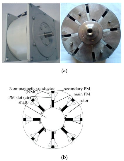
Figure 1.
The new permanent magnet synchronous motor (PMSM): (a) the prototype of the motor; (b) the cross section of the rotor.
The main PMs start to move in the slot once the motor speed exceeds the rated speed. Due to the large magnetic reluctance of the NMC, the effective magnetic flux area provided by the main PMs decreases with the increase in the moving distance of the main PMs. Hence, the air-gap magnetic field is weakened and the FW of the PMSM is realized. The applications of the VMRPMSM possibly include two cases. One is to replace the low-power induction motor which is required to work in a wide speed range and has the advantage of energy conservation of PMSM. The other one is used in industrial machinery with the requirements of low-power and wide speed range.
2.2. The FW Principle
s is defined as the distance between the main PM and the secondary PM. s is related to the motor speed. The leakage flux is usually very small and it is ignored. The no-load magnetic flux distribution is shown in Figure 2.
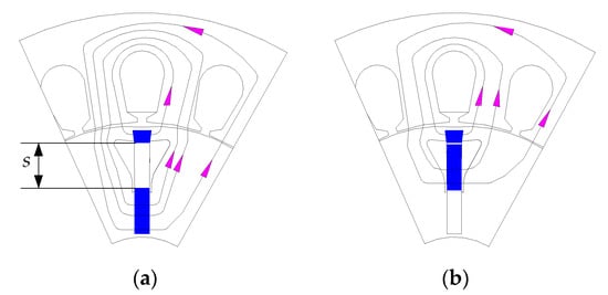
Figure 2.
The magnetic flux path: (a) operating at or below the rated speed (s = 11 mm); (b) operating above the rated speed (s = 0 mm).
The leakage flux and the magnetic reluctance of the stator tooth, the stator yoke and the rotor yoke are ignored due to the high magnetic permeability of the rotor core. The no-load equivalent magnetic circuit diagram is shown in Figure 3.
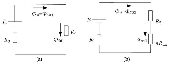
Figure 3.
The equivalent no-load magnetic circuit: (a) s = 11 mm; (b) 0 mm ≤ s < 11 mm (0 < m ≤ 1). Fc is the magnetic potential of the PM. Φm is the magnetic flux provided by the PMs to the external magnetic circuit. Φδ01 and Φδ02 are the air-gap magnetic flux when s = 11 mm and 0 mm ≤ s < 11 mm, respectively. R0, Rδ and Rnm are the magnetic reluctances of the PM, the air gap and the whole NMC, respectively. m is a coefficient from 0 to 1.
Operating at or below the rated speed, the main PMs are fixed in the PM slot and s is 11 mm. The air-gap magnetic flux Φδ01 in Figure 3a is shown as Equation (1):
The main PMs start to move once the speed exceeds the rated speed and operate in a new position steadily. s varies from 11 to 0 mm. Φδ02 in Figure 3b is shown as Equation (2):
The higher motor speed corresponds to the bigger m, thus the mRnm is bigger, so Φδ02 is smaller. Φδ02 is obviously less than Φδ01 due to the large mRnm. Hence, the FW is realized.
The no-load magnetic flux distribution of the motor is shown in Figure 4a. The magnetic flux lines on the right of Figure 4a are obviously sparse compared with that on the left of Figure 4a. The effectiveness of the FW for the motor can be verified. ω is defined as the angle between the magnetomotive force and the direct axis. ω is set as 0°, 45° and 90°, respectively. The rated load magnetic flux distribution of the motor is shown in Figure 4b. The air-gap magnetic field of the motor is distorted due to the effect of the armature field. The load magnetic field lines are distorted in Figure 4b compared with the no-load distribution. The bigger angle results in more distortion when ω varies from 0° to 90°. The magnetic field lines of small s (s = 0 mm) are obviously sparse compared with that of large s (s = 11 mm). The load magnetic field distribution can also indicate the effectiveness of the FW for this motor.
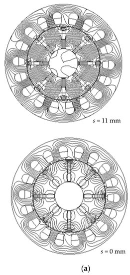
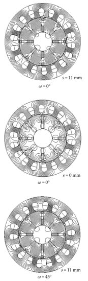
Figure 4.
The magnetic flux distributions (n = 1500 r/min): (a) the no-load distribution; (b) the load distribution with different angle ω.
3. The Electromagnetic Force Analysis
The flux-weakening ability of this VMRPMSM is related to the design of the non-magnetic conductor. However, the design principle of the NMC shape depends on the required electromagnetic force (EF) acting on the main PMs. The relationship between the EF and the motor speed should agree with the variation law of EF required by this flux-weakening principle. Hence, it is necessary to analyze the electromagnetic force.
3.1. The Electromagnetic Force Trend that Meets the Requirement of Flux Weakening
The premise of realizing FW is that the electromagnetic force (EF) must be the increasing function of speed, thus the EF has three cases, as shown in Figure 5.
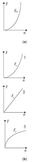
Figure 5.
The force versus motor speed: (a) the centrifugal force Fce; (b) the electromagnetic force Fe (the curves from 1 to 3).
The centrifugal force on the main PMs increases with the motor speed slowly in the beginning and then rapidly. The EF should balance with the centrifugal force. The EF shown in curve 1 of Figure 5 is closest to the centrifugal force, and curve 1 is ideal. Hence, we should design the shape of the NMC so that the EF on the main PMs looks like curve 1.
3.2. The Electromagnetic Force Calculation
The forces acting on the main PMs mainly include the electromagnetic force (EF), the centrifugal force and the friction force. The first main PM in Figure 1 is an example; the forces are shown in Figure 6.
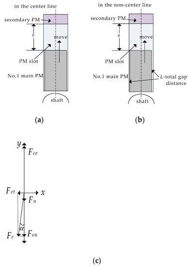
Figure 6.
The forces on the main permanent magnets (PMs): (a) in the centerline of the PM slot; (b) in the non-centerline of the PM slot; (c) the force diagram.
The movement of the main PM is determined by force. The force balance equation on the main PM in Figure 6 is:
where Fce and Fe are the centrifugal force and the EF, respectively. µ is the friction coefficient. is the angle between the EF and the radial center line of the slot. The tangential component of the EF is the positive pressure of the friction force. The radial component of the EF is opposite to the centrifugal force.
Setting the main PMs in the center line of the slot is ideal. The total gap distance L between the main PM and the slot is set as 0.01, 0.02, 0.1 and 0.2 mm, respectively. The EF on the first main PM is shown in Figure 7.
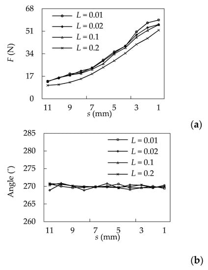
Figure 7.
The electromagnetic force (EF) versus s (in the centerline of the PM slot): (a) the amplitude; (b) the phase.
The EF gradually increases with the decrease in s. The angle of the EF is around 270°. This means the direction of the EF points to the center of the rotor is exactly opposite to the centrifugal force. Meanwhile, the angle of the centerline of the slot is also 270°, thus the angle between the EF and the center line is very small. It means that the positive pressure of friction force is very small due to the small tangential component of the EF. Hence, the friction force can be ignored approximately if the main PMs are located in the centerline of the slot.
In fact, the main PMs will rotate to one side of the PM slot, but the surface of the PM slot cannot be completely smooth. This means there is an air gap between two contact surfaces, so the main PMs are not closely attached to the surface of the PM slot. The deviation ratio is defined as the ratio of the big air-gap distance and the small air-gap distance. The EF on the main PM with different deviation ratios is calculated as shown in Figure 8.
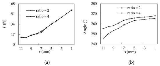
Figure 8.
The EF versus s (in the non-centerline of the PM slot, L = 0.1 mm): (a) the amplitude; (b) the phase.
The deviation angle in Figure 8b between the EF and the center line is larger than that in Figure 7b. The deviation angle reduces as s decreases. The larger deviation ratio increases the deviation angle, and so increases the positive pressure of the friction force. Notably, the friction force is relatively small corresponding to the radial component of the EF. Theoretically, the smaller friction force is good for reducing the calculating speed error according to the force balance.
The influence of the air gap on the EF is shown in Figure 9. The big air gap increases the magnetic reluctance in the magnetic circuit and reduces the air-gap magnetic flux density, thus the EF is reduced.
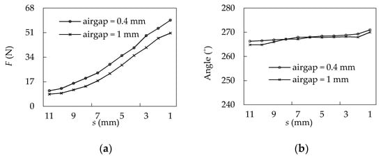
Figure 9.
The effect of the air gap on EF (in the non-centerline, ratio = 2, L = 0.03 mm): (a) the amplitude curve; (b) the phase curve.
The winding current is set as 0.5, 1, 3 and 6 times the rated current; the influence of the winding current on EF is shown in Figure 10. The EF is significantly decreased and the deviation angle increases due to saturation once the current exceeds the value of 6 times the rated current. The amplitude of the EF does not change clearly, while the motor usually runs at less than one times the value of the rated current, so it is not necessary to consider the influence of the current on EF too much.
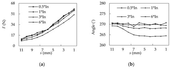
Figure 10.
The effect of the current on EF (in the non-centerline of the PM slot, L = 0.05 mm): (a) the amplitude curve; (b) the phase curve.
The influence of the PM on EF is shown in Figure 11. The thicker PM and the better PM material can provide more magnetic flux density, so the EF on the main PM is bigger.
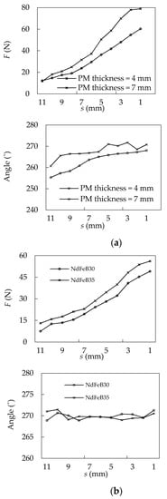
Figure 11.
The effect of the PM thickness and material on EF: (a) the PM thickness (in the non-centerline, ratio = 2, L = 0.03 mm); (b) the PM material (in the non-centerline, L = 0.05 mm).
3.3. Design Idea of the Non-Magnetic Conductor (NMC) According to EF
When s is 11 mm, the motor speed calculated by the balance of the centrifugal force and the sum of the EF and the friction force is approximately equal to 1500 r/min (rated speed). The motor runs more than 1500 r/min, and the relatively low speed corresponds to the small centrifugal force, meaning that the thin NMCs are required. The EF on the main PM corresponding to the increasing centrifugal force should increase synchronously. The change rate of the effective magnetic reluctance provided by the NMC must be larger as speed increases, and thus the EF can be increased. Therefore, the width of the NMC shielding the main PMs should gradually increase. To sum up, the design principle of the NMC should conform to the following two conditions: one is, at low speed, the NMC should be narrow in width. The other one is, as the motor speed increases, the width of the NMC should gradually increase.
4. The Calculation of the Magnetic Reluctance of the Non-Magnetic Conductor
The adjustable exciting reluctance of the motor is mainly provided by the NMCs, so the magnetic resistance value of the NMC is very important. The effect of the dimensional parameters on magnetic reluctance of the NMC is studied, which is beneficial for motor design.
In order to calculate the magnetic reluctance of the NMC conveniently, the NMC is equivalent to an approximate shape, as shown in Figure 12.
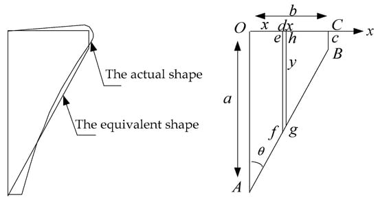
Figure 12.
The shape of the non-magnetic conductor.
θ is defined as the angle between OA and AB. θ can change from 0° to 90°. The hypotenuse of the actual NMC shape is replaced by the line AB. a, b and c are defined as the lengths of OA, OC and CB, respectively. Take a small section of dx on the x-axis, and the height is y. According to the geometric relation, y can be obtained by Equation (4).
The magnetic reluctance of the cross-section efgh in unit axial length is dx/(μ0μnmy). Thus, the magnetic reluctance of the cross-section OABC in axial length of lef is obtained by Equation (5).
where µ0 and µnm are the magnetic permeability of air and the relative magnetic permeability of the NMC, respectively.
The magnetic reluctance of the NMC is greater than zero, so we can get Equation (6) as follows.
S is defined as the cross-section area of the NMC, assuming that the S remains unchanged and it is a constant. Since the length of a is several times greater than the length of c, thus c is designed as 2 mm in this paper. According to the geometry relationship, the S and the θ are derived by Equation (7).
The lengths of a and b are derived from Equation (8) as follows.
k is defined as the length of b divided by the length of a, which is shown in Equation (9).
The lengths of a and b are given according to Equation (8). The parameters of a, b and θ restrict each other under the condition of same S. For example, the increase in θ will lead to the increase in b, and the decrease in a at the same time. The magnetic reluctance derived from Equation (5) versus the parameters of a, b, θ and k are shown in Figure 13.
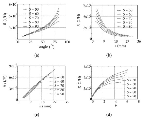
Figure 13.
The magnetic reluctance versus θ, a, b and k: (a) the angle; (b) the length a; (c) the length b; (d) the ratio k.
The larger S of the NMC provides larger magnetic reluctance. Given the same S, the larger θ, the wider b and the shorter a are good for providing larger magnetic reluctance.
Rnm is inversely proportional to the length of a. Rnm increases as k increases, but the increment of the magnetic reluctance slows down. Rnm is approximately proportional to the length of b. The length of b cannot be chosen as too long for rotor space constraints. In addition, the shape design of the NMC is also related to the EF. Hence, the design of the NMC should be considered comprehensively, and reasonable values of a, b and θ should be selected as tradeoffs.
5. The Finite Element Analysis of the NMC
The above theoretical analysis of the EF draws a conclusion that the width of the NMC should be designed to be narrow at low speed and then widen gradually with the increase in speed. The effect of the NMC shape on EF is analyzed by the finite element method to determine whether it is consistent with the theory. In addition, the effect of the NMC on inductance and flux-weakening ability is also studied in this section.
5.1. The Influence of the NMC on EF
The width of the NMC should be designed to be narrow at low speed and then widen gradually with the theoretical increase in speed. In order to verify this, Figure 14 shows the different shape models of the NMC with the same S.
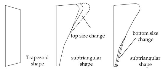
Figure 14.
The shape of the non-magnetic conductor.
The influence of the NMC shape on EF is shown in Figure 15.
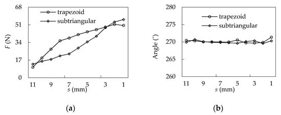
Figure 15.
The influence of the NMC shape on EF (in the centerline): (a) the amplitude curve; (b) the phase curve.
The EF of the model for the trapezoidal NMC matches curve 3 in Figure 5, which is not adapted to the design idea of the NMC. As a comparison, the EF increases first slowly and then rapidly for the sub-triangular NMC, which matches curve 1 in Figure 5 and meets the requirements. Hence, the above analysis from Figure 15 verifies that the sub-triangular shape should be the ideal shape.
The top horizontal width of the sub-triangular NMC in Figure 14 varies from 4 to 8 mm, and the EF on the main PM is shown in Figure 16.
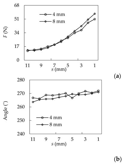
Figure 16.
The effect of the top horizontal width of the sub-triangular NMC on EF (in the non-center line of the slot, ratio = 2, L = 0.03 mm): (a) the amplitude curve; (b) the phase curve.
The top width of the NMC affects EF little under the condition of the large s. As s decreases, the EF difference between the width of 4 and 8 mm of the NMC begins to increase. The wider NMC provides the larger magnetic reluctance and the EF becomes larger. The maximum deviation angles are 6° and 3° for 4 and 8 mm of the NMC, respectively.
The bottom horizontal width of the sub-triangular NMC in Figure 14 varies from 0.5 to 2 mm, and the EF is shown in Figure 17.
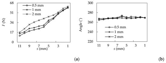
Figure 17.
The effect of the bottom size of the sub-triangular NMC on EF: (a) the amplitude curve; (b) the phase curve.
The wider bottom width of the NMC makes the EF larger. Once the bottom width exceeds 1 mm, the EF does not increase slowly in the beginning and then rapidly with increasing speed, which does not meet the requirement of the FW. Hence, the bottom width is designed to be no more than 1 mm.
The bottom width affects the EF more than the top width under the condition of large s. Hence, the bottom width is more important and should be designed specially. The rated speed is a critical speed at which the main PM starts to move. Hence, the bottom width should be designed to satisfy the balance of its EF and the centrifugal force corresponding to the rated speed under this width. The bottom width is chosen as 1 mm when s is 11 mm by calculation, meanwhile, the EF exactly matches the centrifugal force.
5.2. The Influence of the NMC on Inductance
The effect of the NMC on inductance is shown in Figure 18.
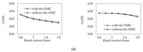
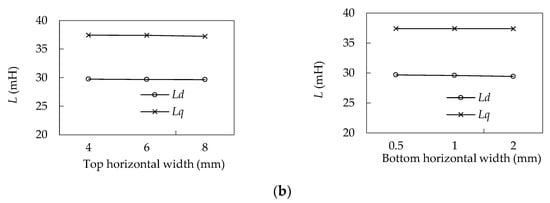
Figure 18.
The effect of the NMC on inductance: (a) the existence of the NMC in the rotor; (b) the different NMC sizes (rated current).
The q-axis inductance (Lq) is larger than that of the d-axis inductance (Ld) whether we put the NMCs in the rotor or not. Meanwhile, the large current results in reducing both the d-axis and the q-axis inductance. The reason is that the large current increases the saturation of the rotor core.
Figure 18b shows that the NMC has little effect on the d-axis inductance and q-axis inductance. The area of the NMC is not large compared to the rotor and it does not affect saturation too much. Meanwhile, the FW of this motor is less dependent on inductance than the common PMSM is. Therefore, in the design of the NMC, it is not necessary to emphasize a consideration of the d-axis inductance and q-axis inductance.
5.3. The Influence of the NMC on FW Ability
The no-load back EMF is derived from Equation (10) as follows.
where n, p, N, Kdp, B, τ and Lef are the motor speed, the numbers of pole pairs, the winding turns, the winding factor of the fundamental wave, the magnetic flux density, the pole pitch and the axial length of the motor, respectively.
For common PMSMs, p, N, Kdp, B, and Lef are close to constants. However, for the new PMSM, the above parameters are constants except for B. The main PMs are located at different positions in the slot, and the magnetic reluctance is different, so the air-gap magnetic flux density is different and it is related to s. The no-load magnetic flux density is shown in Figure 19.
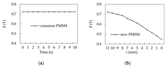
Figure 19.
The no-load air-gap magnetic flux density (n = 1500 r/min): (a) the magnetic flux density versus time for the common PMSM; (b) the magnetic flux density versus s for the new PMSM.
The no-load back EMF of the common PMSM and the new PMSM is shown in Figure 20. The no-load back EMF of the common PMSM in Figure 20a is proportional to motor speed due to constant magnetic flux density. However, as the speed increases, the no-load air-gap magnetic density of the new PMSM is reduced with the increase in motor speed. As the motor speed increases, the distance s becomes smaller and the no-load back EMF is reduced, which is shown in Figure 20b. Thus, it can be seen that reducing the no-load back EMF is an alternative new way to realize FW except for applying a large negative d-axis current.
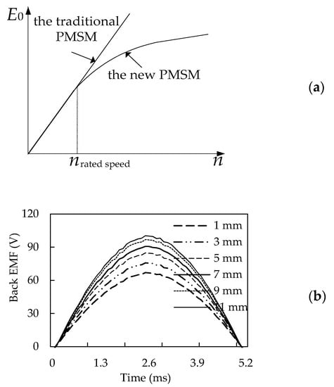
Figure 20.
The no-load back electromotive force (EMF): (a) the no-load back EMF versus speed; (b) the no-load back EMF of the new PMSM versus s (n = 1500 r/min).
The difference of the no-load back EMF between the two extreme positions of the main PMs at the same speed is used to measure the FW effect brought by the special rotor structure rather than the negative d-axis demagnetization current. The extreme positions of the main PMs corresponding to s are 11 and 0 mm, respectively. Good FW ability usually means the larger no-load back EMF difference between the two extreme positions of the main PMs at the same speed. Figure 21 shows the no-load back EMF waveforms with different sizes of the NMC at the speed of 1500 r/min.
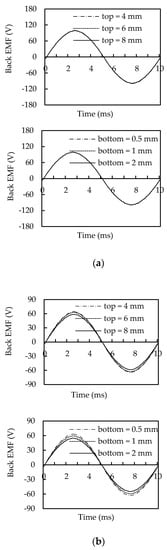
Figure 21.
The no-load back EMF with different top and bottom widths of the NMC (n = 1500 r/min): (a) s = 11 mm; (b) s = 0 mm.
6. Experimental Verification
The design principle of the NMC shape depends on the required electromagnetic force (EF) acting on the main PMs. Under the force condition that determines this NMC shape, the critical speeds are calculated by the corresponding centrifugal force according to force balance on the main PMs when the PMs are in extreme positions (s = 11 mm and s = 0 mm). They are the calculated critical speeds related to the NMC. The measured two critical speeds are obtained by the test of no-load back EMF. Whether the calculated critical speeds according to the force balance are consistent with the measured critical speeds is indirectly reflected in the correctness of NMC design. In this section, the manufacturing process of the NMC is described. The FW validity of the motor is verified by load test. The critical speeds from the no-load back EMF test verify the correctness of the NMC design.
6.1. The Manufacturing Process of the Non-Magnetic Conductor and the Rotor
The manufacturing process of the non-magnetic conductor (NMC) and the rotor is shown in Figure 22.
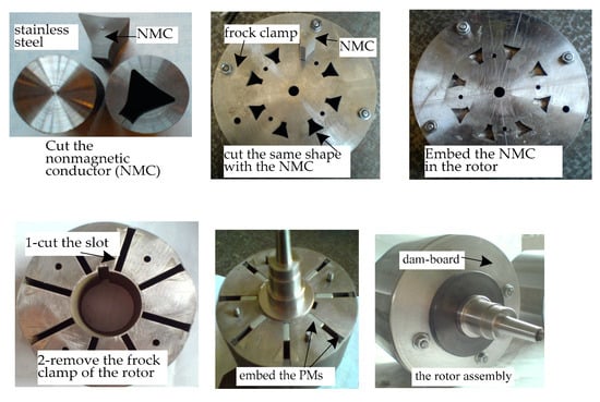
Figure 22.
The prototype of the non-magnetic conductor and the rotor.
Firstly, the two NMCs on both sides of the PM slot are cut out as a whole. Secondly, a frock clamp is made to install and fix on both sides of the rotor core. When cutting some slots in the frock clamp and the rotor core, the shape of the slots is just like the shape of the NMCs. Thirdly, the NMCs are inserted into the rotor core and the frock clamp to make them a subassembly. We cut the PM slot in the subassembly and guarantee the parallelism of the PM slot. The frock clamp is then removed and the surface of the rotor core is polished. The PM slots with good parallelism are processed. Fourthly, the main and the secondary PMs are embedded into the PM slots. Lastly, the two baffles are installed on both sides of the rotor core, and the rotor components are finished.
6.2. The Work Characteristics and the FW Test
The rated parameters and test results of the motor are shown in Table 1.

Table 1.
The rated parameters and test results.
The distance s is changed to adjust the magnetic field for the VMRPMSM. For comparison, the torque–speed curves of the traditional PMSM and the VMRPMSM are calculated by the finite element method. The traditional PMSM with the same size means that s is set as 11 mm and s remains a constant. The load test system, its mechanical characteristics and the efficiency tests are shown in Figure 23.
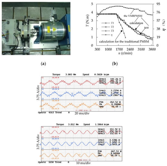
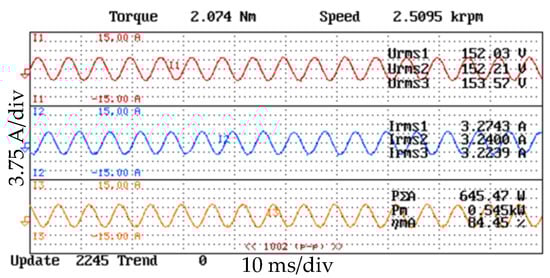
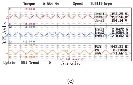
Figure 23.
The working characteristics test: (a) the load experiment test system; (b) the torque and the efficiency of the PMSM based on the principle of variable exciting magnetic reluctance (VMRPMSM) and the traditional PMSM; (c) the measured current and torque operated at 500, 1500, 2500, 3500 r/min.
The test of the rated efficiency for the VMRPMSM is 90%. The efficiency of the motor in whole speed range is good. The VMRPMSM can meet the demand of the rated output power. The maximum measured speed of the motor is 3800 r/min. The FW ability of the VMRPMSM is verified by the experimental test. The maximum motor speed is 2.5 times that of the rated speed. The torque–speed curve calculated by finite element method is basically consistent with the measured curve. As shown in Figure 23b, the speed range of the VMRPMSM is significantly wider than that of the traditional motor.
6.3. The Validation Method of the Correctness of NMC Design
The NMC of the PMSM is very important for realizing FW. The design of the NMC is closely related to the rated speed of the new PMSM. The EF on the main PM located in the initial position as shown in Figure 1 is calculated by the finite element method to get the corresponding centrifugal force. This centrifugal force on the main PM must keep balance with the sum of the EF and the friction force. The special speed corresponding to this exactly calculated centrifugal force is selected as the value of the rated speed.
The main PMs keep stationary at s = 11 mm operated below the rated speed, and the air-gap magnetic flux density is close to a constant. The rated speed of the motor is the critical speed. The main PMs begin to move in the PM slot once the speed of the motor exceeds the rated speed. The main PMs will become stationary again once the forces on them reach a new balance and work steadily at the new position in the PM slot. The air-gap magnetic flux density of the motor working at this new speed is reduced relative to the rated speed. This movement process of the main PMs continues until the main PMs reach to the top of the PM slot. The main PMs always work at the top of the PM slot and become stationary again once the speed of the motor exceeds a critical speed. This corresponding speed is another critical speed. The NMC shape is designed according to the balance of the centrifugal force and the sum of the EF and the friction force on the main PMs at the rated speed. Therefore, the design validity of the NMC can be indirectly reflected by the test of no-load back EMF and the critical speeds.
6.4. The Experimental Test of the NMC
The no-load air-gap magnetic flux density is derived by the Equation (10) as follows.
The prototype is driven by the driving motor, which is shown in Figure 24a. Figure 24c shows the measured waveforms of the no-load back EMF at different speeds. The average effective value of the three phases of the no-load back EMF at 1500 r/min is 70.4 V, which is in agreement with the simulation results in Figure 20. The no-load air-gap magnetic flux density test curve in Figure 24b is derived by testing the no-load back EMF of the prototype according to Equation (11).
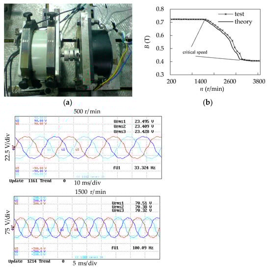
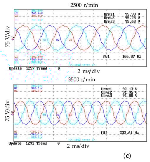
Figure 24.
The validity test of the NMC according to the no-load back EMF test (the speed-up process): (a) the no-load back EMF test; (b) the no-load air-gap magnetic flux density test; (c) the no-load back EMF waveforms at different speeds.
Theoretically, the no-load air-gap magnetic density varies with motor speed in three ways as shown below:
- (1)
- In the first case, the speed is less than 1500 r/min. The centrifugal force on the main PMs is less than the sum of the EF and the friction force, and the main PMs are fixed in the position of s = 11 mm. The no-load air-gap magnetic flux density is close to a constant.
- (2)
- In the second case, the speed varies from 1500 to 3000 r/min. The main PMs can move in the PM slot and keep in balance dynamically, so the no-load air-gap magnetic density is a variable and it is related to the shape of the NMC. The shape of the NMC is an approximate triangle, and the width of the NMC narrows first and then widens later as the motor speed increases. Hence, the no-load air-gap magnetic density is decreased first slowly and then fast as the speed increases theoretically.
- (3)
- In the third case, the speed is more than 3000 r/min. The centrifugal force on the main PMs is larger than the sum of the EF and the friction force, so the main PM is fixed in the position of s = 0 mm. Again, the no-load air-gap magnetic flux density is close to a constant.
The test of the critical speeds for the movement of the main PMs in the speed-up process is shown in Table 2.
Table 2.
The critical speed in the speed-up process.
The rated speed of the motor is designed by the force balance. The shape of the NMC directly affects the EF on the main PMs, so the NMC shape is closely related to the rated speed. The rated speed is the critical speed at which the main PM starts to move. The critical speed is designed as 1500 r/min. The measured speed is 1600 r/min. The error of the designed value and the measured value lies in that the friction force is difficult to estimate exactly; however, the error is acceptable. This indicates that the shape design of the NMC of the prototype is consistent with the analysis.
The experimental results in Figure 24b and Table 2 show that the motor operates below 1600 r/min and the no-load air-gap magnetic flux density is a constant. In the speed range from 1600 to 3100 r/min, the no-load air-gap magnetic flux density declines slowly first and then rapidly with the increase in speed. The test curve of the no-load air-gap magnetic density is consistent with the shape analysis of the NMC. The speed is more than 3100 r/min and the no-load air-gap magnetic flux density remains a constant again. The measured no-load air-gap magnetic flux density is consistent with the theoretical analysis. The correctness and effectiveness of the NMC shape on EF and FW effect are verified.
7. Conclusions
Qualitative analysis, quantitative calculation and testing of the non-magnetic conductor for the new PMSM indicate:
- (1)
- The idea of FW for the VMRPMSM is to reduce the no-load back EMF at high speed, instead of applying a demagnetizing current. The effective magnetic reluctance in the magnetic circuit is changed due to the NMC by the movement of the permanent magnets, thus the no-load back EMF is changed. The speed range is widened by 2.5 times that of the rated speed.
- (2)
- The shape of the NMC depends on the EF required to satisfy the FW. The centrifugal force increases with the speed slowly in the beginning and then rapidly. Theoretically, the width of the NMC should be designed to be narrow at low speed and then widen gradually with the increase in speed according to the EF. The sub-triangular shape is ideal to meet the requirement of the force. The effect of trapezoidal and sub-triangular NMC on EF by finite element method indicates that the EF increases with the speed slowly in the beginning and then rapidly for the motor of sub-triangular NMC. This verifies that the sub-triangular shape is ideal, which is consistent with the theoretical analysis.
- (3)
- The no-load air-gap magnetic density is a variable. It keeps constant, variable and constant when s = 11 mm, 0 mm < s < 11 mm and s = 0 mm, respectively. The critical speeds are calculated for s = 11 mm and s = 0 mm by the corresponding centrifugal force according to force balance on the main PMs. According to the force balance, the NMC shape should be designed to make sure that the critical movement speed of the main PMs is exactly equivalent to the rated speed. The measured two critical speeds are obtained by the test of no-load back EMF. The measured critical speeds agree with the calculated critical speeds and that verifies the correctness of the shape design of the NMC.
- (4)
- The NMC affects the EF on the main PMs greatly while the NMC has little effect on the inductance. The inductance design does not need to consider the NMC. The wider NMC is beneficial for the FW ability of the motor. The NMC is chosen to be as wide as possible to enlarge the FW under the condition of the requirements of the EF.
Author Contributions
Analysis, investigation and validation, C.L.; supervision, B.K.; writing—original draft preparation, F.G. and C.L.; writing—review and editing, T.M. All authors have read and agreed to the published version of the manuscript.
Funding
This research was supported in part by the National Natural Science Foundation of China under Grant 51307045, in part by the Heilongjiang Natural Science Foundation under Grant LH2019E075, in part by the Heilongjiang Provincial Education Department Foundation under Grant KJCX201915 and TSTAU-C2018014, in part by the Heilongjiang University Outstanding Youth Science Foundation under Grant JCL201705.
Institutional Review Board Statement
Not applicable.
Informed Consent Statement
Not applicable.
Data Availability Statement
All data are given in the paper. Separately there is no other data.
Conflicts of Interest
The authors declare no conflict of interest.
References
- Nishio, H.; Machida, K. Magnetic anisotropy effects on squareness ratio of Nd-Fe-B sintered magnets with different coercivity. IEEE Trans. Magn. 2020, 56, 2100604. [Google Scholar] [CrossRef]
- Zhang, J.; Liu, J.; Yang, J.; Zhao, N.; Wang, Y.; Zheng, T. A modified DC power electronic transformer based on series connection of full-bridge converters. IEEE Trans. Power Electron. 2019, 34, 2119–2133. [Google Scholar] [CrossRef]
- Ma, K.; Choi, U.M.; Blaabjerg, F. Prediction and validation of wear-out reliability metrics for power semiconductor devices with mission profiles in motor drive application. IEEE Trans. Power Electron. 2018, 33, 9843–9853. [Google Scholar] [CrossRef]
- Chen, H.; Lee, C. Parametric sensitivity analysis and design optimization of an interior permanent magnet synchronous motor. IEEE Access 2019, 7, 159918–159929. [Google Scholar] [CrossRef]
- Ekanayake, S.; Dutta, R.; Rahman, F.; Xuan, B.M. Performances of a fractional-slot concentrated-winding permanent magnet synchronous machine under position sensorless control in deep flux-weakening region. IEEE Trans. Ind. Appl. 2019, 55, 5938–5946. [Google Scholar] [CrossRef]
- Wang, X.; Reitz, M.; Yaz, E.E. Field oriented sliding mode control of surface-mounted permanent magnet AC motors: Theory and applications to electrified vehicles. IEEE Trans. Veh. Technol. 2018, 67, 10343–10356. [Google Scholar] [CrossRef]
- Zhang, Z.; Wang, C.; Zhou, M.; You, X. Parameters compensation of permanent magnet synchronous motor in flux-weakening region for rail transit. IEEE Trans. Power Electron. 2020, 35, 12509–12521. [Google Scholar] [CrossRef]
- Zhang, Z.; Wang, C.; Zhou, M.; You, X. Flux-weakening in PMSM drives: Analysis of voltage angle control and the single current controller desgin. IEEE J. Emerg. Sel. Top. Power Electron. 2019, 7, 437–445. [Google Scholar] [CrossRef]
- ELLoumi, N.; Bortolozzi, M.; Masmoudi, A.; Mezzarobba, M.; Olivo, M.; Tessarolo, A. Numerical and analytical approaches to the modeling of a spoke type IPM machine with enhanced flux weakening capability. IEEE Trans. Ind. Appl. 2019, 55, 4702–4714. [Google Scholar] [CrossRef]
- Dang, L.; Bernard, N.; Bracikowski, N.; Berthiau, G. Design optimization with flux weakening of high-speed PMSM for electrical vehicle considering the driving cycle. IEEE Trans. Ind. Electron. 2017, 64, 9834–9843. [Google Scholar] [CrossRef]
- Chai, F.; Zhao, K.; Li, Z.; Gan, L. Flux weakening performance of permanent magnet synchronous motor with conical rotor. IEEE Trans. Magn. 2017, 53, 8208506. [Google Scholar] [CrossRef]
- Kong, Y.; Lin, M.; Jia, L. A novel high power density permanent-magnet synchronous machine with wide speed range. IEEE Trans. Magn. 2020, 56, 7505206. [Google Scholar] [CrossRef]
- Zheng, Y.; Wu, L.; Fang, Y.; Huang, X.; Lu, Q. A hybrid interior permanent magnet variable flux memory machine using two-part rotor. IEEE Trans. Magn. 2019, 55, 8106008. [Google Scholar] [CrossRef]
- Dutta, R.; Rahman, M.F. Design and analysis of an interior permanent magnet (IPM) machine with very wide constant power operation range. IEEE Trans. Energy Convers. 2008, 23, 25–33. [Google Scholar] [CrossRef]
- Kim, K.C. A novel magnetic flux weakening method of permanent magnet synchronous motor for electric vehicles. IEEE Trans. Magn. 2012, 48, 4042–4045. [Google Scholar] [CrossRef]
- Wang, D.; Peng, C.; Xue, D.; Zhang, D.; Wang, X. Performance assessment and comparative study of a permanent magnet machine with axial flux regulator. IEEE Trans. Energy Convers. 2019, 34, 1522–1531. [Google Scholar] [CrossRef]
- Wang, D.; Zhang, D.; Xue, D.; Peng, C.; Wang, X. A new hybrid excitation permanent magnet machine with an independent AC excitation port. IEEE Trans. Ind. Electron. 2019, 66, 5872–5882. [Google Scholar] [CrossRef]
- Wang, M.; Tong, C.; Song, Z. Performance analysis of an axial magnetic-field-modulated brushless double-rotor machine for hybrid electric vehicles. IEEE Trans. Ind. Electron. 2019, 66, 806–817. [Google Scholar] [CrossRef]
- Wang, C.; Zhu, Z.Q. Fuzzy logic speed control of permanent magnet synchronous machine and feedback voltage ripple reduction in flux-weakening operation region. IEEE Trans. Ind. Appl. 2020, 56, 1505–1517. [Google Scholar] [CrossRef]
- Bedetti, N.; Calligaro, S.; Petrella, R. Analytical design and autotuning of adaptive flux-weakening voltage regulation loop in IPMSM drives with accurate torque regulation. IEEE Trans. Ind. Appl. 2019, 56, 301–313. [Google Scholar] [CrossRef]
- Xu, W.; Ismail, M.M.; Liu, Y.; Islam, M.R. Parameter optimization of adaptive flux-weakening strategy for permanent-magnet synchronous motor drives based on particle swarm algorithm. IEEE Trans. Power Electron. 2019, 34, 12128–12140. [Google Scholar] [CrossRef]
- Chen, J.J.; Chin, K.P. Automatic flux-weakening control of permanent magnet synchronous motors using a reduced-order controller. IEEE Trans. Power Electron. 2000, 15, 881–890. [Google Scholar] [CrossRef]
- Bolognani, S.; Calligaro, S.; Petrella, R. Adaptive flux-weakening controller for interior permanent magnet synchronous motor drives. IEEE J. Emerg. Sel. Top. Power Electron. 2014, 2, 236–248. [Google Scholar] [CrossRef]
- Su, D.; Zhang, C.; Dong, Y. An improved continuous-time model predictive control of permanent magnetic synchrounous motors for a wide-speed range. Energies 2017, 10, 2051. [Google Scholar] [CrossRef]
- Tursini, M.; Chiricozzi, E.; Petrella, R. Feedforward flux-weakening control of surface mounted permanent magnetic synchronous motors accounting for resistive voltage drop. IEEE Trans. Ind. Electron. 2010, 57, 440–448. [Google Scholar] [CrossRef]
- Lin, X.; Huang, W.; Jiang, W. Position senseless direct torque control for six-phase permanent magnet synchronous motor under two-phase open circuit. IET Electr. Power Appl. 2019, 13, 1625–1637. [Google Scholar] [CrossRef]
- Choi, Y.S.; Choi, H.H.; Jung, J.W. Feedback linearization direct torque control with reduced torque and flux ripples for IPMSM drives. IEEE Trans. Power Electron. 2016, 31, 3728–3737. [Google Scholar] [CrossRef]
- Nasr, A.; Gu, C.; Bozhko, S.; Gerada, C. Performance enhancement of direct torque-controlled permanent magnet synchronous motor with a flexible switching table. Energies 2020, 13, 1907. [Google Scholar] [CrossRef]
- Bao, G.; Qi, W.; He, T. Direct torque control of PMSM with modified finite set model predictive control. Energies 2020, 13, 234. [Google Scholar] [CrossRef]
- Ekanayake, S.; Dukmi, R.; Rahman, F.; Xuan, B.M. Direct torque and flux control of interior permanent magnet synchronous machine in deep flux-weakening region. IET Electr. Power Appl. 2018, 12, 98–105. [Google Scholar] [CrossRef]
- Kim, S.; Seok, J.K. Finite-settling-steps direct torque and flux control for torque-controlled interior PM motors at voltage limits. IEEE Trans. Ind. Appl. 2014, 50, 3374–3381. [Google Scholar] [CrossRef]
- Nguyen, T.D.; Foo, G.; Tseng, K.J.; Vilathgamuwa, D.M. Modeling and sensorless direct torque and flux control of a dual air gap axial flux permanent magnet machine with field weakening operation. IEEE-ASME Trans. Mechatron. 2013, 19, 412–422. [Google Scholar] [CrossRef]
Publisher’s Note: MDPI stays neutral with regard to jurisdictional claims in published maps and institutional affiliations. |
© 2021 by the authors. Licensee MDPI, Basel, Switzerland. This article is an open access article distributed under the terms and conditions of the Creative Commons Attribution (CC BY) license (http://creativecommons.org/licenses/by/4.0/).