Abstract
The present article deals with the concept of the non-metallic flat plate liquid solar collector and its evaluation. The innovative concept lies in the elimination of metal parts of the solar collector and their replacement by the foam glass block, which significantly reduces the energy and material demands of the production process. The evaluation of the collector took place in two phases, the first was focused on the numerical evaluation, which resulted in the compilation of a theoretical curve of the efficiency of the solar collector. The second phase was focused on verifying the basic functionality of the concept based on the results obtained from experimental tests of the collector, which confirmed the functionality of the concept and revealed several areas that will need to be addressed in the further development of the prototype.
1. Introduction
One of the essential conditions for the sustainable development of modern society is the necessity to ensure the energy supply in the required quantity and quality while minimizing possible negative impacts on the environment [1,2,3,4,5,6]. From an environmental point of view, the continued use of fossil fuels is one of the biggest risks [7,8,9,10,11,12,13,14]. The biggest environmental, but also industrial, challenge facing modern society is the gradual replacement of fossil fuels and, respectively, drastic reduction in fossil fuel consumption. One of the ways to achieve this goal is the wider use of renewable energy sources in the energy mix of individual countries [15,16,17,18,19,20,21]. In terms of consumption of primary energy sources, RES (renewable energy sources) provided more than 7000 TWh in 2019, which represents more than 11% of total energy production [22]. When looking at electricity production, RES provided 26.2% of the total electricity production [23]. From the whole range of renewable energy sources, one of the greatest theoretical, but also real, technical potentials is solar energy [24]. This source is possible to use in many ways, mostly to produce electricity using PV systems or heat using solar collector systems [25,26,27,28,29,30,31]. In the European Union, the installed capacity of photovoltaics is 117 GWe [32] and 36.1 GWth in thermal solar systems [33], the vast majority of which are installed in smaller scales at the family houses, etc. The present article deals with the use of solar energy to produce heat in the form of hot water, which is produced using an innovative non-metallic solar collector that was designed and manufactured by the authors. The concept of a non-metallic solar collector is based on the experience the authors gained in the process of assessing the technical and operational parameters of commercially produced and available flat plate solar collectors. From this experience, it can be stated that the currently produced flat plate liquid solar collectors are built exclusively on a metal basis, apart from air collectors and low-efficiency swimming pool solar heaters that are made of polypropylene or other plastics. In the construction of the absorber, metals with high thermal conductivity, i.e., copper and aluminum, are used [34]. The use of metallic materials is associated with an increase in energy [35] and technological complexity of production [36], high prices [37] of manufacturing equipment, and last, but not least, the high thermal conductivity of metallic parts, which can negatively affect the increased rate of heat losses from the collector body. Due to these facts, the authors needed to find a different conceptual strategy for capturing and obtaining heat by the body of the solar collector with the exclusion of metal elements from the energy-conversion part of the collector.
It can be assumed that the replacement of metal construction materials with cheaper non-metallic materials will lead to a reduction in the total cost of production of the solar collector, which should be reflected in the final price of the product. However, this can occur only while maintaining a similar operational efficiency in the solar collector. Another positive aspect is the reduction of manufacturing energy consumption by excluding the most energy-intensive materials from the construction of the solar collector, which is directly reflected in the reduction of the energy payback period of the solar system. The reduction of energy required for production has a positive environmental effect in an area that is often a subject of criticism in relation to renewable energy sources, namely, the considerable energy and, partly, the raw material intensity of the manufacturing process [38]. The mentioned energy intensity is often the result of the use of highly sophisticated technological processes and design solutions. The reduction of manufacturing energy consumption by the conversion of construction materials towards less energy-intensive represents only a partial, but time-immediate, elimination of the above-mentioned phenomenon.
The concept of the non-metallic flat plate liquid solar collector proposed by the authors is presented at the level of structural design, prototype construction, numerical evaluation, and experimental operation, which was carried out to verify the basic functionality of the concept, in particular the structural integrity of the individual parts.
2. Materials and Methods
2.1. Basic Concept of Non-Metallic Solar Collector
The basic philosophy of the proposed design is based on the change in the material and construction layout of the proposed solar collector. The presented concept consists of four main construction parts—foam glass insulating block with a top surface coating, transparent glazing, pillars, and connecting fittings. In the presented concept, the black non-selective surface coating of the foam glass insulating block acts as an absorber and, therefore, creates a photothermal converter. On this surface, shortwave solar radiation is converted into heat, which is directly transferred to the heat transfer medium. Figure 1 (left) shows, in a partial cross-section view, the basic arrangement of parts and the energy balance of the solar collector. The figure depicts heat fluxes representing heat gains and losses, where qs is solar radiation, qh,loss is the heat loss from the transparent cover and the back of the collector, qopt,loss are optical losses caused by reflection and absorption of radiation through the transparent cover, qabs is the heat flux dissipated by the absorber (i.e., useful heat), tm is the temperature of the heat transfer medium, tabs is the temperature of the absorber, τ is the transmittance of the solar collector glazing.
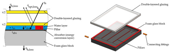
Figure 1.
Cross-section of a proposed non-metallic solar collector with depicted basic parts and energy balance (left) and exploded view of the 3D model of the proposed solar collector (right).
The heat transfer from the surface of the absorber to the body of the foam glass block is prevented by the high thermal resistance of the foam glass. In comparison to a conventional absorber, which is characterized by significant heat loss from the front of the absorber in the presented design, this loss is eliminated by the structural layout of parts. The back of the absorber is thermally insulated comparable to a conventional solar collector. A heat transfer medium flows in front of the top surface of the absorber, dissipating heat from the absorber body. Above the heat transfer medium is the lower glass of the transparent cover, which contributes to the elimination of heat loss due to its thermal resistance. Thus, the upper surface of the lower glass is equivalent to the surface of the metal absorber of a conventional solar collector, however, the surface temperature of the glass is lower and, at the same time, the heat flux through the glass is lower.
In the above-mentioned arrangement of the absorber, energy gain is achieved by direct absorption of solar radiation during its passage through the layer of heat transfer liquid, when a fraction of UV radiation is used. The heating of the heat transfer media also occurs under the diffuse component of the solar radiation, while a higher degree of extinction is manifested in the part of the spectrum with a longer wavelength (red light). Part of the light that penetrates the water is scattered; a part is absorbed and converted into heat. However, this method of heating cannot be overestimated due to the very thin layer of liquid. From the point of view of the passage of solar radiation through a thin layer of liquid, it is possible to speak of a negligible influence, concerning the values of light transmittance at wavelengths that are characteristic of solar radiation [39].
2.2. Prototype of a Non-Metallic Solar Collector
The designed and constructed prototype of a non-metallic solar collector consists of four main parts, as is depicted in Figure 1 (right):
- (a)
- conversion-insulating foam glass block fulfilling the role of a frame with a sealing-delimiting surface,
- (b)
- transparent cover,
- (c)
- pillars,
- (d)
- connecting fittings.
Due to the limited offer of foam glass, the prototype has dimensions of 600 × 450 mm, but the concept can be used analogously in the construction of a collector of classic dimensions (i.e., 2000 × 1000 mm). In the proposed concept of the solar collector, we considered the use of a block construction of the solar collector body, which integrates the thermal insulation and the back enclosure frame, respectively, into one block. This block is also part of the heat transfer fluid distribution system, which functions as an absorber and, respectively, a photothermal converter. The key part of the proposed collector, the conversion-insulating block, is made of foam glass. This material has good thermal insulation properties and, in comparison with other insulating materials, has the advantage of higher compressive strength, chemical inertness, and water resistance at low weight (ρ = 120 to 165 kg.m−3) [40]. Foam glass is produced by foaming glass crumbs together with pulverized coal. Since this insulating material has closed pores, it is completely watertight in its entire volume and, at the same time, non-absorbent for all liquids. For this reason, neither its thermal resistance nor its volume changes over time. Foam glass has the highest compressive strength among thermal insulation materials (compressive strength 0.7 to 1.2 MPa depending on the type). At the same time, it has high rigidity, is practically incompressible, and is resistant to extreme temperatures. In the case of the proposed collector, the block has a plate shape, and its thickness is determined by ensuring sufficient thermal resistance of the block and sufficient rigidity of the structure (frame function). Due to the value of the coefficient of thermal conductivity λ, which in the case of foam glass is 0.038 to 0.048 W.m−1.K−1 [41], it was possible to consider the total thickness of the insulating part of the block of 60 mm. The foam glass block also contains openings for connection fittings and tear-shaped recesses serving as a distribution or the collecting section of the flow channels as seen in Figure 2. Foam glass properties are summarized in Table 1.
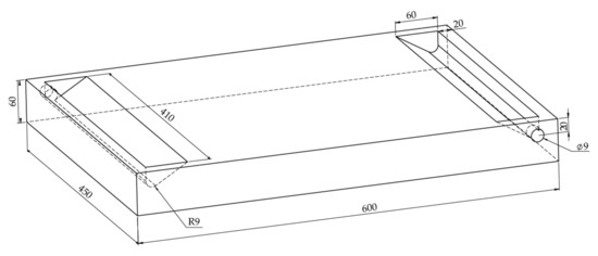
Figure 2.
Foam glass block with dimensions of the constructed prototype.

Table 1.
Basic foam glass properties [40].
In the production process of the prototype, foam glass with the trade name T4 was used. The upper side of the block was made of foam glass, respectively, the side in contact with the heat transfer medium was treated with a 1 mm thick black, hygroscopic, heat-resistant polyurethane coating. The black matte coating on the foam glass acts as a solar absorber and increases the durability of the foam glass structure. The collector area was divided into four flow channels, which are delimited by pillars made of silicone sealant. The width of the pillar is 7 mm; its length is 415 mm, and its height is 3 mm, i.e., the thickness of the layer of heat transfer medium is 3 mm. The width of the four flow channels is 97.25 mm. The thickness of the heat transfer medium was chosen to keep the liquid volume of the solar collector at an acceptable level, in this case, 0.81 L.
The upper part of the collector is formed by insulating double-layered glazing, which consists of a pair of 4 mm thick Solarglass glasses with a transmissivity value τ = 0.78 and a heat transfer coefficient k = 0.8 W.m−2.K−1. The use of a transparent cover, which is characterized by the use of two glasses with evacuated space between them (as is depicted in Figure 3 right), was conditioned by the effort to minimize heat transfer from the top of the solar collector and, thus, by the effort to reduce heat loss of the proposed device. Since the inner glazing of the transparent cover is in direct contact with the liquid, it must withstand thermal and pressure stress; for that reason, it was a specifically chosen glass, designed for solar applications. Although in conventional collectors, this glass is not in contact with the heat transfer medium, its chemical composition and production process makes it possible to assume its resistance in the proposed use, which was verified by a test operation in which no problems with the transparent cover appeared. The pressure of water in the hydraulic circle was set to 650 kPa, following the design of a typical flat plate solar collector. The gap between the pair of glasses is 20 mm. The dimensions of the glazing correspond to the size of the collector, i.e., 600 × 450 mm. The transparent cover was attached to the foam glass block with a silicone sealant, which transmits the hydrostatic pressure of the heat transfer fluid. The proposed solar collector was connected to the hydraulic circuit using connecting fittings made of brass pipes with a diameter of 18 mm, which form the only metal part of the proposed solar collector. The structural design and the dimensions of the parts are shown in Figure 3, where the proposed solar collector is presented in front, cross-section view, and in the detailed view of the individual layers of the solar collector.
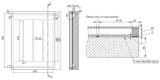
Figure 3.
The structural design and the dimensions of the parts.
The heat transfer medium is introduced into the solar collector by a copper connection fitting, located in the lower-left corner. The significant teardrop-shaped widening, visible in Figure 2, allows the developing flow from the circular cross-section into the rectangular cross-section flow channels of the solar collector without the formation of significant turbulent areas. In the main part of the solar collector, the flow of the heat transfer medium is divided into four streams; this segmentation allows the designers to achieve a uniform volumetric flow rate of the heat transfer medium. This ensures homogeneous heating of the medium by the incident solar radiation. The basic building element of the proposed solar collector is a block made from the prepared raw foam glass plate. The raw foam glass block had to be adjusted to the required dimensions, discussed above. The production also included a surface treatment, which consisted of a surface roughness treatment and chamfering of the edges. The next step was to make the desired shape of the distribution, respectively, the collection channel of teardrop shape, and to drill holes enabling the introduction of copper pipe sections serving as a connection with the hydraulic circuit of the measuring apparatus. After these treatments, the whole block was painted with a hydrophobic coating. After the coating had hardened, copper fittings were glued with a hydrophobic epoxy. The final step was the creation of dividing pillars and the installation of a transparent glass cover. In this step, water-soluble auxiliary blocks were used, which ensured the distance of the transparent cover from the foam glass block to provide the required gap, since the pillars would not be able to maintain the weight of the transparent cover in the unhardened state. The advantage of the procedure we used is that after the pillars have hardened, the auxiliary blocks are dissolved in water and flushed from the internal volume of the collector. The manufactured foam glass block with connection fittings and raw foam glass material are depicted in Figure 4.
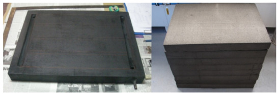
Figure 4.
The prototype of the foam glass block with surface treatment (left) and raw foam glass plates (right).
2.3. Methodology
The evaluation of the collector took place in two phases: the first was focused on the numerical evaluation, which resulted in the compilation of a theoretical curve of the efficiency of the solar; the second phase was focused on verifying the basic functionality of the concept, based on the results obtained from experimental tests of the collector. The evaluation of the collector was carried out in the months May and June, at the Renewable Energy Center, Faculty BERG. This center is located in Košice, Slovakia (latitude 48°43′ N and longitude 21°15′ E); the area is characterized as a temperate climate zone. A prototype of the proposed solar collector was installed on a measuring apparatus and connected to the hydraulic circuit shown in Figure 5. The inclination of the collector was 45°, which represents the optimal value for a given geographical location and selected time of year [42].
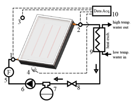
Figure 5.
The schematic diagram of the hydraulic circuit and measuring apparatus with depicted positions of measuring devices (1, 2—inlet and outlet thermocouples, 3—ambient air thermocouple, 4—solarimeter, 5—flowmeter, 6—circulation pump, 7—expansion vessel, 8—flow control valve, 9—heat exchanger, 10—data acquisition system).
The assembly of the hydraulic circuit was based on the principle that the circulation pump must operate in the cold branch of the hydraulic circuit, and that its heat output must not affect the heat transfer medium behind the temperature probes. The assembly of the solar collector connected to the hydraulic circuit was placed on a semi-mobile platform, which represented certain limitations in terms of available space, which necessitated some compromises such as the relative position of the valve and the circulation pump. In the presented arrangement, the service life of the pump could be reduced during long-term operation due to cavitation, but in the short-term operation of a given experimental system, this is not a major problem.
The basic characteristic that defines the solar collector in terms of its use is the solar collector thermal efficiency curve. Based on the shape and parameters of the curve, solar collectors can be evaluated and compared with each other. The thermal efficiency of a solar collector is generally defined as the ratio of the energy transferred by a heat transfer medium over a period of time, to the product of a solar collector absorber area and the solar radiation incident on the solar collector under steady-state conditions. This ratio can be termed as an energy balance equation and has the form [43,44]:
where η is solar collector thermal efficiency, qA is the heat flux dissipated by the absorber (i.e., the useful heat flux dissipated by the heat transfer medium), G is a solar radiation intensity, A is an absorber area, product τ·a is referred to as solar collector optical efficiency, k is the coefficient of heat loss, tm is a mean heat transfer medium temperature, te is an ambient temperature. The ratio (tm − tE)/G [m2.K.W−1] is called the reduced temperature difference determined for the solar collector and is one of the basic parameters for evaluating the thermal efficiency of solar collectors under different operating conditions [45]. Based on these theoretical findings, the basic linear curve of collector efficiency is numerically defined results section.
In the tests process, water was used as the heat transfer medium. The measuring apparatus consisted of a series of KIMO TTKE-363 thermocouples (type K, range −40 °C to +400 °C) placed according to Figure 5 in the hydraulic circuit, which recorded the temperature of the heat transfer medium at the inlet and outlet of the collector and the ambient temperature, and in the body of the proposed solar collector according to Figure 6, which records the temperature of the heat transfer medium in the various locations in the proposed solar collector.
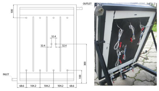
Figure 6.
Position of thermocouple probes and real image of the backside of the prototype.
Thermocouple data were recorded by the KIMO AMI 300 data acquisition system with a thermocouple module with an uncertainty of ±0.8 °C. The volumetric flow rate of the heat transfer medium was set using a TACOSETTER 100 rotameter with a measurement uncertainty of ±5% (F.S.). The intensity of solar radiation was recorded with a KIMO SL200 solarimeter, which operates with 5% accuracy and a recording frequency of 2/s. The solar cell operates in the range from 400 to 1300 nm. When measuring the intensity of solar radiation, it was necessary to compromise by using a solarimeter at the expense of a pyranometer. This compromise was forced by the availability of a solarimeter and, respectively, the unavailability of a pyranometer in the workplace. The used solarimeter operates in the wavelength range from 400 to 1300 nm, i.e., it covers the visible and most of the IR part of the spectrum from the solar spectral irradiance point of view. Although wavelengths above 1300 nm affect the energy balance of the solar collector, it is possible in our opinion, to accept the use of this device. This is mainly because the values of solar radiation intensity were no longer used in the evaluation of the thermal technical properties of the solar collector, such as the calculation of thermal efficiency. The intensity of solar radiation was mainly data that characterizes the insulating conditions of a specific measuring day.
3. Results
The numerical evaluation of the proposed solar collector was performed by numerical methods, which resulted in a theoretical curve of the thermal efficiency of the solar collector and the determination of the theoretical value of the stagnation temperature of the solar collector. The calculation itself used a widely accepted methodology based on the values of the overall transparency and absorptivity of the transparent cover and the heat transfer coefficient of the foam glass block.
The optical losses of the proposed solar collector are given by the product of the solar transmittance coefficient of the collector glazing τ = 0.78 and the solar radiation absorption coefficient according to [46] a = 0.94. The total optical loss then has a coefficient value (τ·a) = 0.73. The maximum value of the reduced temperature difference (tm − tE)/G corresponds to the stagnation state, which is the state of operation of the solar collector when the heat transfer medium does not circulate through the solar collector, but the absorber is exposed to solar radiation and, thus, captured heat is not removed. The value of the maximum stagnation state temperature tA,max is given by Equation (2), which is based on the above-mentioned Equation (1).
In the conditions of Central Europe, the maximum temperature tA,max of the solar collector in equilibrium state is determined either experimentally in tests of the solar collector or by calculation for the solar radiation intensity of G = 1000 W.m−2 [47] and the ambient temperature of te = 30 °C [48]. The presented calculation considers the heat transfer coefficient k = 3 Wm−2.K−1, which corresponds to the lowest quality level of the double-glazing structure of the transparent cover and the value of the heat transfer coefficient on the back of the collector k2 = 0.4 Wm−2.K−1 (normally for conventional solar collectors, k2 is at the level of 0.3 to 0.5 Wm−2.K−1 [48]).
Subsequently, the total heat transfer coefficient of the solar collector is k = 3.4 W.m−2.K−1. However, to calculate the maximum temperature of the absorber, due to the higher surface temperatures according to [48], it is necessary to correct the value of k using a correction factor c, which has the value c = 1.12 for k in the presented range. Then, the corrected total heat transfer coefficient of the collector is k′ = 3.8 W.m−2.K−1. Then, tA,max is 222 °C, and the value of the parameter x, i.e., the reduced temperature difference (tm − tE)/G is 0.222.
Based on these data, it is possible to compile a theoretical linear curve of the thermal efficiency of the presented solar collector, which is shown in Figure 7. A tabular representation of the thermal efficiency calculated with the use of the energy balance equation and input data according to [48] is given in Table 2.
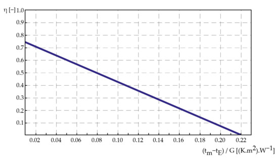
Figure 7.
The theoretical linear curve of the proposed solar collector thermal efficiency depending on x parameter.
Table 2.
The thermal efficiency of the proposed solar collector for selected temperature difference and intensity of solar radiation.
4. Discussion
4.1. Basic Evaluation of the Functionality of the Solar Collector
The functionality of the prototype of the proposed solar collector was evaluated based on the results of performed tests, which were specifically designed to reveal possible deficiencies in the concept before the actual evaluation of the thermal efficiency of the solar collector, which quantifies the operation of the proposed solar collector in terms of energy efficiency. The basic functionality was evaluated by a test that can be characterized by the stagnation state of the solar collector, and tests the monitored changes in the temperature of the heat transfer medium in the longitudinal profile of the solar collector, as well as changes in the temperature of the transparent cover and the rear wall of the insulation block.
The purpose of the tests marked as A, B, C was to verify the structural integrity of the foam glass block, which is affected by the fluid pressure and to verify the functionality and tightness of the connection between the foam glass block and the transparent cover. Tests also verifed the increase in the temperature of the heat transfer medium in the proposed solar collector, as well as the temperature of the outer surfaces of the solar collector, which would indicate critical points when occurring increased heat losses. The stagnant and quasi-stagnant state exposes the solar collector to increased thermal and pressure-induced stresses, which allow the manifestation of various design and manufacturing errors.
4.1.1. Test A
This test aimed to confirm the assumption that the change in solar radiation intensity has a characteristic effect on the development of temperature parameters of the solar temperature system, and to determine the maximum temperature values that the solar collector can reach, under-insulated conditions, with the limited quasi-stagnation flow. The input parameters of the test are characterized by a clear to semi-clear sky, with an ambient temperature of 24 °C. The initial temperature of the heat transfer medium was 22 °C, and its flow rate reached an almost negligible value in terms of the transferred heat output. In numerical terms, the flow rate of the heat transfer medium was set to 0.001389 L.s−1. The test was performed between 11:47 and 13:30 when the solar collector was exposed to sunlight and the surrounding atmospheric influence. However, the recording of values itself took place in three intervals as shown in Table 3.
Table 3.
Temperatures of each thermocouple probes (Tn) and values of solar radiation intensity (I).
The measurement confirmed the good functionality of the device, from the point of view of achieving high temperature values of the heat transfer medium in all profiles and, respectively, measuring points. An increase in temperature with time and increasing intensity of sunlight is also visible.
4.1.2. Test B
The purpose of this measurement was to obtain outputs whose values describe the relationship between the temperature development of the transparent cover and the rear insulating part of the collector, in connection to increasing the temperature of the working substance, in a certain time interval, under specific ambient conditions. The input parameters of the test were again characterized by a clear to semi-clear sky with low clouds and an ambient temperature of 21.0 °C, the initial temperature of the working substance was 21.3 °C, and a quasi-stagnant flow state (0.001389 L.s−1) was also considered again. The test was performed from 9:02 to 9:52 and the data were evaluated in ten-minute intervals. During the test, the value of solar radiation reached 500 W.m−2 (±5 W.m−2 fluctuations). The evaluated prototype was equipped with thermocouple probes at the middle of the transparent cover area and, secondly, in the middle of the back wall of the solar collector area. The values of the measured temperatures are summarized in Table 4.
Table 4.
The temperature of thermocouple probes located in the inlet (T1), in the middle of the transparent cover (Ttrans_cover), in the middle of the back wall of the insulation layer (Tback_wall), and in the middle of the flow channel (T5).
During the measurement, the ambient temperature increased; this condition is also recorded in Table 4. By analyzing the measurements, it was found that there is a slight increase in temperature both on the side of the transparent cover and on the side of the insulating layer, which can be seen in Figure 8 and Figure 9. However, their increment is minimal and is mainly related to the balance of the temperature of the monitored areas with the ambient temperature, as well as to the influence of diffuse radiation emitted from various reflecting surfaces of the surrounding environment.
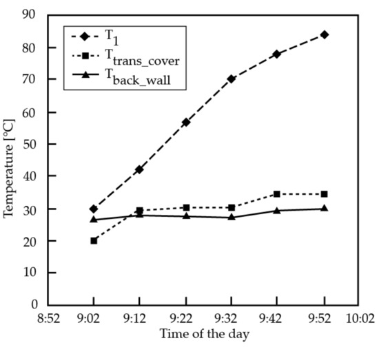
Figure 8.
Temperature development of thermocouple probe in inlet position, transparent cover, and back wall of insulation block.
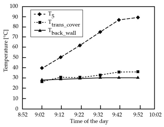
Figure 9.
Temperature development of thermocouple probe in inlet position, transparent cover, and back wall of insulation block.
4.1.3. Test C
The measurement was performed to characterize the temperature increase in individual levels of the collector field, due to the change in the amount of accumulated energy, due to the predominance of the diffuse component of solar radiation. In this test, semi-cloudy weather with more pronounced diffusion radiation prevailed; the ambient temperature was 23 °C and the initial temperature of the working substance was 16.4 °C. Again, the solar collector was tested under a quasi-stagnation state, with a minimum flow rate of 0.001389 L.s−1. The measurement results summarized in Table 5 show that the individual layers of the collector array are also affected by the change in the intensity of solar radiation. For evaluation, we chose individual thermocouples from each level (T1, T5, T7), which in the monitored interval reached the temperatures listed in the table of values.
Table 5.
Temperatures of each thermocouple probes (Tn) and values of solar radiation intensity (I).
From the graphical representation in Figure 10, it is evident that there is a comparable influence of individual outputs at all levels, in terms of the amount of incident solar energy. The characteristic change occurs only at the initial value of the T1 probe, which is located in channel One. It is most subject to the influence of the inflow of heat transfer medium at a given time. After repeated measurements, when the temperature has stabilized, this change no longer manifests itself, and the effect of the intensity of solar radiation is, in this case, comparable to the others.
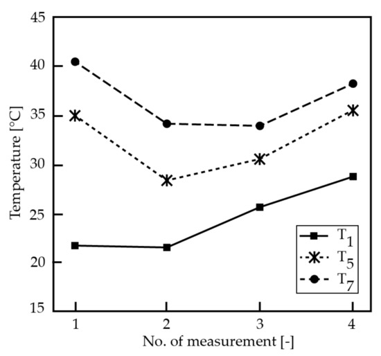
Figure 10.
Temperature increases at individual solar collector levels.
4.2. Identification of Possible Design Risks and Their Elimination
During the production of the prototype, and also in the experiments, several problem areas were identified, in terms of the concept or manufacturing. These problems will need to be addressed before the next phase of research or commercial deployment.
The anticipated risks are:
- Ensuring the transparency of the heat transfer medium distribution system in the solar collector. The transparency of this element has a significant effect on the thermal efficiency of the heat exchange processes in the absorber. Possible sources of pollution are:
- Incrustation on the walls of the absorber channels. Incrustation on the glass surface has a direct effect on the level of penetration of solar radiation into the absorber area (reduction of radiation intensity, an increase in optical losses of the collector). Incrustation on the conversion surface of the foam glass block reduces the rate of conversion of solar radiation into heat. The elimination measure consists of the use of a high-purity heat transfer medium without incrustation additives. The proposed solar collector cannot be operated in an open hydraulic circuit in which directly heated water flows through the collectors.
- Development of algae or other organisms causing gradual deterioration of the heat transfer fluid or the solar collector itself. This risk is particularly acute, as it can be assumed that the conditions in the absorber channels will be suitable for the life and reproduction of simple living organisms, especially green algae and cyanobacteria. It is not possible to rely on reaching and exceeding the pasteurization temperature during the operation of the solar system, because, in times of prevailing optimal conditions (low solar radiation intensity and, therefore, the low temperature of heat transfer medium), organisms can multiply in a short time and cause deterioration of the entire system. Probably the only effective measure to ensure permanently abiotic conditions is to add a suitable inhibitor to the heat transfer medium. However, the inhibitor must not affect the required properties of the heat transfer fluid and must also be suitable for use in water heating systems. From the above, it can be assumed that the collectors will not be able to operate in Drain-back systems.
- Ensuring the stability and coherence of the solar collector as a result of the pressure action of the heat transfer fluid. The very nature of the proposed concept implies the greater sensitivity of the construction to the increased fluid pressure in comparison with the metal pipes of conventional solar collectors. The elimination of this risk has its limits, given by the concept itself. Increasing the area of the pillars naturally entails a reduction in the net area of the absorber and, thus, a reduction in the energy production of the solar collector. The strength parameters of the pillars are determined by the type of used material and its bonds with the surface. Here, it is possible to search for more durable materials and a method of surface preparation for the best possible bonding of the joint. Another way to eliminate this problem is to operate the collector in such conditions that it is not exposed to an enormous increase in pressure due to heating of the heat transfer medium or hydrostatic pressure action of the fluid column at a high vertical configuration of the gravitational hydraulic circuit. A possible way to eliminate this risk is to use the collector in a thermosiphon configuration with an integrated tank located just above the collector, where the advantage of low hydraulic resistance of the collector could also be used.
- The high weight of the solar collector. If we consider a solar collector with an area 2 × 1 m and a foam glass block with a thickness of 6 cm with a bulk density of 140 kg.m−3 (interval is 125–150 kg.m−3), the weight of the foam glass block is approximately 17 kg. The weight of transparent double-layered glazing with a glass thickness of 4 mm with a total area of 2 × 2 m2 is 40 kg. The total gross weight of the solar collector is then about 60 kg. Compared to conventional flat plate solar collectors, it is about 15 kg more. The possibility of weight reduction is limited mainly by the use of two glasses; however, it is possible to consider lightweight glass or thinner borosilicate glass. In this calculation was considered the bulk density of the foam glass at the upper interval. When using a lighter type, together with lower thermal conductivity or thickness, (however, it is necessary to take into account the strength limits), it is possible to partially reduce the weight of the foam glass block.
5. Conclusions
The present paper deals with the design and evaluation of an innovative concept of a non-metallic flat plate liquid solar collector. The proposed concept considers the exclusion of metal parts from the energy-conversion part of the solar collector and their replacement by a foam glass block, and presents a change in philosophy regarding conducting the heat transfer medium. It can be assumed that the replacement of metal construction materials with cheaper non-metallic materials will lead to a reduction in the total cost of production of the solar collector, which should be reflected in the final price of the product. However, this must occur while maintaining a similar operational efficiency of the solar collector. Another positive aspect is the reduction of manufacturing energy consumption by excluding the most energy-intensive materials from the construction of the solar collector, which is directly reflected in the reduction of the energy payback period of the solar system. The key part of the proposed solar collector, the conversion-insulating block, is made of foam glass. This material has good thermal insulation properties and, in comparison with other insulating materials, has the advantage of higher compressive strength, chemical inertness, and water resistance at low weight The prototype designed and built by the authors was evaluated theoretically and by performed tests. The numerical evaluation resulted in the construction of a theoretical linear curve of the thermal efficiency of the solar collector and the calculation of the stagnation temperature. The corrected total heat transfer coefficient of the collector is k′ = 3.8 W.m−2.K−1 and tA,max is 222 °C. Subsequently, a functional prototype of the proposed solar collector was installed in an experimental measuring apparatus, enabling the tested operation of the solar collector and recording of its basic operating characteristics. The evaluation of the collector was carried out in the months of May and June, at the Renewable Energy Center, Faculty BERG. This center is located in Košice, Slovakia (latitude 48°43′ N and longitude 21°15′ E); the area is characterized as a temperate climate zone. The data obtained from the simulated operation verified the basic functionality of the proposed concept, but it is necessary to perform further measurements during the simulated operation, as well as measurements that will result in the compilation of the thermal efficiency curve of the proposed solar collector. As part of the evaluation, the risk points of the design were identified and theoretically discussed, which could reduce the overall efficiency of the solar collector or limit its application potential.
Author Contributions
Conceptualization, R.R. and M.B.; methodology, M.B.; validation, M.B.; data curation, M.B., T.M., S.Z., K.B. and J.D.; writing—original draft preparation, R.R. and M.B.; writing—review and editing, R.R. and M.B.; visualization, M.B. All authors have read and agreed to the published version of the manuscript.
Funding
This paper was created in connection with the project VEGA 1/0290/21 Study of the behavior of heterogeneous structures based on PCM and metal foams as heat accumulators with application potential in technologies for obtaining and processing of the earth resources. This research was funded by the Scientific Grant Agency of the Ministry of Education, Science, Research and Sport of the Slovak Republic (VEGA). This paper was created in connection with the project 048TUKE-4/2021 Universal educational—competitive platform.
Institutional Review Board Statement
Not applicable.
Informed Consent Statement
Not applicable.
Conflicts of Interest
The authors declare no conflict of interest.
References
- Armeanu, D.Ş.; Vintilă, G.; Gherghina, Ş.C. Does Renewable Energy Drive Sustainable Economic Growth? Multivariate Panel Data Evidence for EU-28 Countries. Energies 2017, 10, 381. [Google Scholar] [CrossRef]
- Garshasbi, S.; Haddad, S.; Paolini, R.; Santamouris, M.; Papangelis, G.; Dandou, A.; Methymaki, G.; Portalakis, P.; Tombrou, M. Urban mitigation and building adaptation to minimize the future cooling energy needs. Sol. Energy 2020, 204, 708–719. [Google Scholar] [CrossRef]
- Abd Alla, S.; Simoes, S.G.; Bianco, V. Addressing rising energy needs of megacities—Case study of Greater Cairo. Energy Build. 2021, 236, 110789. [Google Scholar] [CrossRef]
- Nadimi, R.; Tokimatsu, K. Fundamental energy needs quantification across poor households through simulation model. Energy Procedia 2019, 158, 3795–3801. [Google Scholar] [CrossRef]
- Vogt Gwerder, Y.; Marques, P.; Dias, L.C.; Freire, F. Life beyond the grid: A Life-Cycle Sustainability Assessment of household energy needs. Appl. Energy 2019, 255, 113881. [Google Scholar] [CrossRef]
- Wei, C.; Li, C.; Löschel, A.; Managi, S.; Lundgren, T. Digital technology and energy sustainability: Impacts and policy needs. Resour. Conserv. Recycl. 2021, 170, 105559. [Google Scholar] [CrossRef]
- Oryani, B.; Koo, Y.; Rezania, S. Structural Vector Autoregressive Approach to Evaluate the Impact of Electricity Generation Mix on Economic Growth and CO2 Emissions in Iran. Energies 2020, 13, 4268. [Google Scholar] [CrossRef]
- Nie, X.; Zhao, T.; Su, Y. Fossil fuel carbon contamination impacts soil organic carbon estimation in cropland. Catena 2021, 196, 104889. [Google Scholar] [CrossRef]
- Solarin, S.A. An environmental impact assessment of fossil fuel subsidies in emerging and developing economies. Environ. Impact Assess. Rev. 2020, 85, 106443. [Google Scholar] [CrossRef]
- Silva, L.F.O.; Santosh, M.; Schindler, M.; Gasparotto, J.; Dotto, G.L.; Oliveira, M.L.S.; Hochella, M.F., Jr. Nanoparticles in fossil and mineral fuel sectors and their impact on environment and human health: A review and perspective. Gondwana Res. 2021, 92, 184–201. [Google Scholar] [CrossRef]
- Gaete-Morales, C.; Gallego-Schmid, A.; Stamford, L.; Azapagic, A. Life cycle environmental impacts of electricity from fossil fuels in Chile over a ten-year period. J. Clean. Prod. 2019, 232, 1499–1512. [Google Scholar] [CrossRef]
- Schroth, A.W. Impacts of Anthropocene Fossil Fuel Combustion on Atmospheric Iron Supply to the Ocean. Encycl. Anthr. 2018, 1, 103–113. [Google Scholar]
- Hanif, I. Impact of fossil fuels energy consumption, energy policies, and urban sprawl on carbon emissions in East Asia and the Pacific: A panel investigation. Energy Strategy Rev. 2018, 21, 16–24. [Google Scholar] [CrossRef]
- Machol, B.; Rizk, S. Economic value of U.S. fossil fuel electricity health impacts. Environ. Int. 2013, 52, 75–80. [Google Scholar] [CrossRef]
- Hori, K.; Kim, J.; Kawase, R.; Kimura, M.; Matsui, T.; Machimura, T. Local energy system design support using a renewable energy mix multi-objective optimization model and a co-creative optimization process. Renew. Energy 2021, 96, 105174. [Google Scholar] [CrossRef]
- Ahn, K.; Chu, Z.; Lee, D. Effects of renewable energy use in the energy mix on social welfare. Energy Econ. 2021, 96, 105174. [Google Scholar] [CrossRef]
- Cany, C.; Mansilla, C.; Mathonnière, G.; da Costa, P. Nuclear contribution to the penetration of variable renewable energy sources in a French decarbonised power mix. Energy 2018, 150, 544–555. [Google Scholar] [CrossRef]
- Faúndez, P. Renewable energy in the equilibrium mix of electricity supply sources. Energy Econ. 2017, 67, 28–34. [Google Scholar] [CrossRef]
- Hong, S.; Bradshaw, C.J.A.; Brook, B.W. Global zero-carbon energy pathways using viable mixes of nuclear and renewables. Appl. Energy 2015, 143, 451–459. [Google Scholar] [CrossRef]
- Milstein, I.; Tishler, A. Intermittently renewable energy, optimal capacity mix and prices in a deregulated electricity market. Energy Policy 2011, 39, 3922–3927. [Google Scholar] [CrossRef]
- Tafarte, P.; Das, S.; Eichhorn, M.; Thrän, D. Small adaptations, big impacts: Options for an optimized mix of variable renewable energy sources. Energy 2014, 72, 80–92. [Google Scholar] [CrossRef]
- BP Statistical Review of World Energy 2019; BP plc: London, UK, 2019; pp. 5–10.
- Renewable Energy Statistics 2019; The International Renewable Energy Agency: Abu Dhabi, UAE, 2019; pp. 380–398.
- Perez, R.; Perez, M. A fundamental look at energy reserves for the planet. Int. Energy Agency SHC Programme Sol. Update 2009, 50, 2–3. [Google Scholar]
- Wu, Y.; Li, C.; Tian, Z.; Sun, J. Solar-driven integrated energy systems: State of the art and challenges. J. Power Sources 2020, 478, 228762. [Google Scholar] [CrossRef]
- Leonzio, G. Solar systems integrated with absorption heat pumps and thermal energy storages: State of art. Renew. Sustain. Energy Rev. 2017, 70, 492–505. [Google Scholar] [CrossRef]
- Nema, P.; Nema, R.K.; Rangnekar, S. A current and future state of art development of hybrid energy system using wind and PV-solar: A review. Renew. Sustain. Energy Rev. 2009, 13, 2096–2103. [Google Scholar] [CrossRef]
- Alahmer, A.; Ajib, S. Solar cooling technologies: State of art and perspectives. Energy Convers. Manag. 2020, 214, 112896. [Google Scholar] [CrossRef]
- Karimirad, M.; Rosa-Clot, M.; Armstrong, A.; Whittaker, T. Floating solar: Beyond the state of the art technology. Sol. Energy 2021, 219, 1–2. [Google Scholar] [CrossRef]
- Al-Shahri, O.A.; Ismail, F.B.; Hannan, M.A.; Hossain Lipu, M.S.; Al-Shetwi, A.Q.; Begum, R.A.; Al-Muhsen, N.F.O.; Soujeri, E. Solar photovoltaic energy optimization methods, challenges and issues: A comprehensive review. J. Clean. Prod. 2021, 284, 125465. [Google Scholar] [CrossRef]
- Ravi Kumar, K.; Krishna Chaitanya, N.V.V.; Sendhil Kumar, N. Solar thermal energy technologies and its applications for process heating and power generation—A review. J. Clean. Prod. 2021, 282, 125296. [Google Scholar] [CrossRef]
- Jäger-Waldau, A. PV Status Report 2019, EUR 29938 EN; Publications Office of the European Union: Luxembourg, 2019; pp. 10–12. [Google Scholar]
- Solar Heat Markets in Europe (Summary 2019), Solar Heat Europe; ESTIF: Brussels, Belgium, 2019; pp. 1–6.
- Evangelisti, L.; De Lieto, R.; Asdrubali, V.F. Latest advances on solar thermal collectors: A comprehensive review. Renew. Sustain. Energy Rev. 2019, 114, 109318. [Google Scholar] [CrossRef]
- Horodníková, J.; Khouri, S.; Rybár, R.; Kudelas, D. TESES rules as a tool of analysis for chosen OZE projects. Acta Montan. Slovaca 2008, 13, 350–356. [Google Scholar]
- Kosai, S.; Yamasue, E. Global warming potential and total material requirement in metal production: Identification of changes in environmental impact through metal substitution. Sci. Total Environ. 2019, 651, 1764–1775. [Google Scholar] [CrossRef] [PubMed]
- Taušová, M.; Horodníková, J.; Khouri, S. Financial analysis as a marketing tool in the process of awareness. Acta Montan. Slovca 2007, 12, 258–263. [Google Scholar]
- Kommalapati, R.; Kadiyala, A.; Shahriar, M.T.; Huque, Z. Review of the Life Cycle Greenhouse Gas Emissions from Different Photovoltaic and Concentrating Solar Power Electricity Generation Systems. Energies 2017, 10, 350. [Google Scholar] [CrossRef] [Green Version]
- Said, Z.; Sajid Hossain, M.; Abd Rahim, N. Evaluating the Optical Properties of TiO2 Nanofluids for a Direct Absorption Solar Collector. Numer. Heat Transf. Appl. 2015, 67, 1–18. [Google Scholar]
- König, J.; Lopez-Gil, A.; Cimavilla-Roman, P.; Rodriguez-Perez, M.A.; Petersen, R.; Østergaard, M.B.; Iversen, N.; Yue, Y.; Spreitzer, M. Synthesis and properties of open- and closed-porous foamed glass with a low density. Constr. Build. Mater. 2020, 247, 118574. [Google Scholar] [CrossRef]
- Arriagada, C.; Navarrete, I.; Lopez, M. Understanding the effect of porosity on the mechanical and thermal performance of glass foam lightweight aggregates and the influence of production factors. Constr. Build. Mater. 2019, 228, 116746. [Google Scholar] [CrossRef]
- Jacobson, M.Z.; Jadhav, V. World estimates of PV optimal tilt angles and ratios of sunlight incident upon tilted and tracked PV panels relative to horizontal panels. Sol. Energy 2018, 169, 55–66. [Google Scholar] [CrossRef]
- Vengadesan, E.; Senthi, R. A review on recent developments in thermal performance enhancement methods of flat plate solar air collector. Renew. Sustain. Energy Rev. 2020, 134, 110315. [Google Scholar] [CrossRef]
- Khedher, N.B. Experimental Evaluation of a Flat Plate Solar Collector Under Hail City Climate. Eng. Technol. Appl. Sci. Res. 2018, 8, 2750–2754. [Google Scholar] [CrossRef]
- Chaji, H.; Ajabshirchi, Y.; Esmaeilzadeh, E.; Zeinali Heris, S.; Hedayatizadeh, M.; Kahani, M. Experimental Study on Thermal Efficiency of Flat Plate Solar Collector Using TiO2/Water Nanofluid. Mod. Appl. Sci. 2013, 10, 60–69. [Google Scholar] [CrossRef]
- Tiwari, G.N.; Tiwari Shyam, A. Handbook of Solar Energy, Theory, Analysis and Applications; Springer: Singapore, 2016; pp. 171–246. [Google Scholar]
- Cihelka, J. Solar Thermal Technology; T. Malina Publishing: Praha, Czech Republic, 1994; pp. 64–71. [Google Scholar]
- Rybár, R. Use of Alternative Energy Sources in Urban Areas. Doctoral Dissertation, Technical University of Košice, Košice, Slovakia, 2001. [Google Scholar]
Publisher’s Note: MDPI stays neutral with regard to jurisdictional claims in published maps and institutional affiliations. |
© 2021 by the authors. Licensee MDPI, Basel, Switzerland. This article is an open access article distributed under the terms and conditions of the Creative Commons Attribution (CC BY) license (https://creativecommons.org/licenses/by/4.0/).