Review

Stationary Hybrid Renewable Energy Systems for Railway Electrification: A Review

by
Sergey V. Mitrofanov
1,*,
Natalya G. Kiryanova
1,2,* and
Anna M. Gorlova
2,3,4
1
Faculty of Energetics, Novosibirsk State Technical University, 630073 Novosibirsk, Russia
2
Scientific Center for Information Technologies and Artificial Intelligence, Sirius University of Science and Technology, 354340 Sochi, Russia
3
Heterogeneous Catalysis Department, Boreskov Institute of Catalysis SB RAS, 630090 Novosibirsk, Russia
4
Faculty of Natural Sciences, Novosibirsk State University, 630090 Novosibirsk, Russia
*
Authors to whom correspondence should be addressed.
Energies 2021, 14(18), 5946; https://doi.org/10.3390/en14185946
Submission received: 2 September 2021 / Revised: 13 September 2021 / Accepted: 15 September 2021 / Published: 18 September 2021

Abstract

:
This article provides an overview of modern technologies and implemented projects in the field of renewable energy systems for the electrification of railway transport. In the first part, the relevance of the use of renewable energy on the railways is discussed. Various types of power-generating systems in railway stations and platforms along the track, as well as in separate areas, are considered. The focus is on wind and solar energy conversion systems. The second part is devoted to the analysis of various types of energy storage devices used in projects for the electrification of railway transport since the energy storage system is one of the key elements in a hybrid renewable energy system. Systems with kinetic storage, electrochemical storage batteries, supercapacitors, hydrogen energy storage are considered. Particular attention is paid to technologies for accumulating and converting hydrogen into electrical energy, as well as hybrid systems that combine several types of storage devices with different ranges of charge/discharge rates. A comparative analysis of various hybrid electric power plant configurations, depending on the functions they perform in the electrification systems of railway transport, has been carried out.

1. Introduction

To date, rail transport is one of the largest users of electricity, both in Russia and in other countries with developed and actively developing economies (USA, France, Spain, China, and a number of other countries).
According to the strategy of scientific and technical development of the JSC Russian Railways [1], the goal of the transport sector by 2030 is to reduce greenhouse gas emissions to 20% below the level of 2008, which corresponds to the Resource Efficient Europe roadmap set out in the Europe 2020 Strategy.
The commitment of the Netherlands Railways to provide all-electric trains with 100% renewable energy (RE) was achieved in 2017 ahead of schedule [2].
It is planned that by 2021, the national rail transport of India will use up to 1 GW of solar energy [3]. Work is underway on projects to create complexes of solar panels installed on roofs, which will have a total capacity of up to 500 MW. Currently, a significant number are in operation, including at 900 railway stations. Their total capacity is 100 MW. In the future, Indian Railways can use 51,000 hectares of unused land to build solar power plants (SPPs) with a total capacity of up to 20 GW. Recently, Indian Railways announced their plans to use up to 200 MW of wind energy on the railways of India by 2021. The theoretical potential of solar energy capacity at India’s rail transport facilities is estimated at 266.034 GW [4].
One of the main disadvantages of RE is the instability of its generation, which leads to the inability of the power system to meet the consumer’s demand at any time. A way to solve this problem is to use various energy storage devices, for example, batteries, flywheels, electric double-layer capacitors, etc. The excess of energy generated by the RE power system can be stored and then supplied back to the grid when the energy generated at a certain moment from renewable sources is not enough to meet the demand.
In addition to various physical and electrochemical storage systems, energy can be stored in the form of hydrogen produced by water electrolysis using renewable sources. When the demand for electricity arises, hydrogen is supplied to a fuel cell (FC), where electricity is generated because of the electrochemical reaction of oxygen reduction from the air with hydrogen [5,6]. According to the Technology Roadmap—Hydrogen and Fuel Cells by the International Energy Agency [7], by 2025, hydrogen technologies should penetrate all energy sectors, CO2 capture technologies in hydrogen production should be improved, and the number of hydrogen storage systems suitable for integrating into energy systems based on RE sources should be increased. Thus, the importance of introducing hydrogen energy into the transport sector and, specifically, the electrification of railway transport is recognized by the world community [7].
The paper is organized as follows. In Section 2, different configurations of solar and wind power plants are described, a comparative analysis of such systems is given. In Section 3, energy storage systems (ESS) and their feasibility for railway electrification systems are discussed, the best options are chosen based on the analysis. Hydrogen technologies for hybrid renewable energy systems (HRES) are presented in Section 4. Hydrogen production by water electrolysis using RE is discussed, and a comparative analysis of different types of hydrogen FCs is given. Particular attention is paid to the role of hydrogen technologies in HRES for railway electrification.

2. Renewable Energy Systems for Railway Transport Electrification

The most used renewable energy systems (RES) are SPPs based on photovoltaic converters and wind farms. Most hybrid systems consider these types due to their greater versatility compared to other RE sources. Micro-hydro turbine power plants can also be used as an energy source. This type of RES is the most cost-effective, which was clearly demonstrated in [8,9], but the use of micro-hydro turbine power plants is strongly limited by the geographical peculiarities of the area.
Among the possible options for introducing RE sources into the electrification systems of railway transport, the following groups of design solutions can be defined by the type of RE source:
  • Power generation systems based on photovoltaic converters;
  • Generation systems based on wind power plants;
  • Hybrid generation systems.
Depending on the region and climatic conditions of the area, it may be economically acceptable to use systems based on one energy source or a combination of several sources. According to the report [10], the use of solar energy conversion systems is relevant for countries such as India, Saudi Arabia, Egypt, and Argentina, but not for the countries of northern Europe, for example, Sweden, Norway, and Finland. At the same time, some regions with low solar radiation can use wind energy quite efficiently. As a rule, these are countries with coastal territories and highlands or states located near the Arctic Circle.
In accordance with the recommendations of the International Union of Railways [11], the following options for the location of RES at railway transport facilities can be defined, presented in Figure 1.

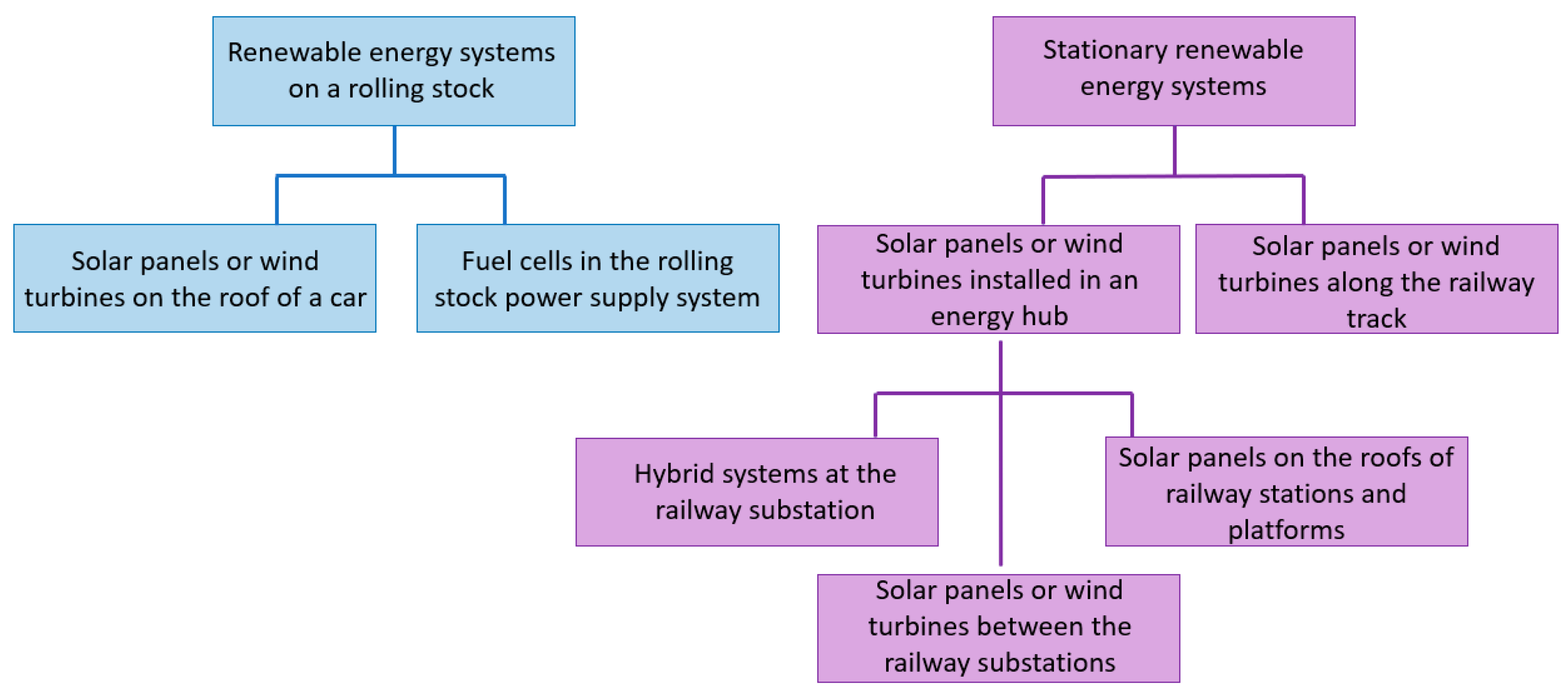
2.1. Renewable Energy Systems Installed on Rolling Stock

Installation of photoelectric converters on the roof of a train is the most convenient option for generating systems on rolling stock [12]. Researchers and engineers from southern countries, such as India [13,14,15,16], Ethiopia [17], Malaysia [18], etc., are showing particular interest in this technology due to the high level of insolation in these regions. PECs are compact, easy to operate, and do not require frequent maintenance due to the absence of moving parts. They can be installed horizontally on the roof, with minimal changes in the aerodynamic properties of the train.
In [19], the design of compact low-power wind turbines (WTs) with a vertical rotation axis of the rotor for mounting on the roof of a wagon is considered. The rated power of the WT is 3.6 kW. Generation systems similar in design are given in [20,21,22,23,24]. However, such a solution can cause an increase in the drag coefficient of the train, which will lead to an increase in the power consumption of the main traction motors. In addition, the presence of moving parts in the WT mechanism requires periodic maintenance and repair.

2.2. Stationary Renewable Energy Systems

The use of stationary systems using RE sources allows generating more “green” energy. This is due to the absence of restrictions on the scaling of generating plants for large areas and the use of proven designs for generating plants.

2.2.1. Wind Turbines with a Vertical Rotation Axis Installed along Railroad

The installation of wind generators with a vertical rotation axis along the railroad makes it possible to effectively use the airflow transverse to the direction of the train movement, which occurs when the train passes near the turbines. A feature of this type of WT is lower minimum operating speeds. They begin to work at a minimum speed of 1.5–2 m/s, in contrast to WTs with a horizontal rotation axis. They are more efficient at low wind speeds and reach the nominal operating mode at a speed of 10–12 m/s, which is important in low-wind areas and when using the wind flow generated by the movement of the train. Examples of such systems are presented in [25,26,27]. The power of a generator varies, depending on the model and dimensions, in a range from four hundred W to several tens of kW; however, the number of installed WTs is limited only by the length of the railway tracks and the terrain. The efficiency of these plants directly depends on the density of train traffic through the considered section of the railway track. As shown by the results of a simulation presented in [26], 10 Kliux Zebra WTs with a nominal capacity of 4 kW are capable of generating 32.3 MW∙h during the year. Similarly, in [27] with 10 WTs with a nominal capacity of 1.8 kW, located in a tunnel along the train route, showed the possibility of generating power of 79.83 MW∙h during the year. In [28], the design options for WTs with S-rotor and H-rotor are considered, the pros and cons of both systems are analyzed, and the higher efficiency of WT placement at the exit from the tunnels is substantiated in comparison with the placement of WTs in open areas.
As mentioned above, the unit power of this type of WT does not exceed several kW, which requires the installation of a large number over a long distance along the railway. Local connection of each individual installation to the overhead line through a converter is technically difficult and expensive since the rated voltage of the WT does not exceed 1000 V AC, while the rated voltage of the overhead line can reach 12–24 kV DC. The centralized connection scheme, at one or several points, will require the laying of a large number of cable lines along the tracks, which will have a significant impact on both the volume of capital costs and the level of losses in power lines on the way from the WT to the end consumer. This option is convenient for low-power consumers in the immediate vicinity of WTs. For example, for lighting systems or signal lamps on various sections of the railway track.

2.2.2. Wind Parks for Railway Electrification

The above-described versions of WT systems with a vertical axis of rotation are used in small wind power (wind turbines with a capacity of up to 100 kW). However, train and rail auxiliary systems are not the only application for wind energy.
The connection of large wind farms with high-power WTs with a horizontal axis of rotation makes it possible not only to cover the needs of the railway and household consumption but also to supply power to such a powerful consumer as an overhead line. This solution will not only reduce the consumption of electricity from the power system and thus reduce the carbon footprint of the railway company, but also improve the quality of electricity by compensating for voltage fluctuations in long inter-substation sections of the railway. A group of Chinese scientists [29,30,31] clearly demonstrated the positive effects of connecting a wind farm, caused by an increase in voltage in the connectivity nodes, and a negative effect on the quality of electricity and the total harmonic distortion in the system.
The power of the connected wind farms can vary from one hundred kW to tens of MW. For example, in Mongolia, a wind farm with an installed capacity of up to 50 MW is planned to supply power to railways, as well as SPPs, the first of which has already been put into operation; its capacity is 10 MW [32].
It should be noted that for the effective operation of large wind farms in the region, there must be sufficiently high average annual wind speeds. The most successful areas for the installation of WTs are considered to be coastal and high-mountain areas. Engineers from China have made significant progress in the projects for the integration of large-capacity wind parks (up to 20 MW) with an overhead railway line, which is described in detail in [29,30,31,33].
Wind farms can be connected to the railway electrification system through substations in the area of the railway stations, but the most optimal is the installation of additional power plants in the railway inter-substation zones at an equal distance from the substations. This will significantly reduce the power and voltage losses in the overhead line and will provide a greater freight-carrying capacity of the railway, reducing the likelihood of a power deficit in the rolling stock locomotive.
It should be noted that wind farms with a capacity exceeding 1 MW often operate in parallel with the power system, while lower power systems are used as part of hybrid microgrid systems, together with other types of RE sources and energy storage. Applications for hybrid systems in rail transport will be discussed in more detail in Section 2.2.5.

2.2.3. Photovoltaic Converters on the Roofs of Railway Stations and the Surrounding Area

SPPs based on photovoltaic converters are the most versatile option for RES because, unlike micro-hydroelectric power plants, photovoltaic converters are less tied to the source of energy and can be installed in any area and on almost any surface. At the same time, they do not have rotating parts, unlike WT, which greatly simplifies their operation and increases reliability.
Installing photovoltaic panels on railway station roofs, sheds over platforms, openings between railway lines, soundproof and windproof walls, and maintenance depot roofs is a very practical solution. It avoids the alienation of a significant plot of land for the construction of a solar station and ensures the location of the energy source in close proximity to consumers, which may be the station’s household needs.
Many developing (India, Pakistan, Vietnam, Malaysia, Turkey, etc.) and developed countries (Australia, Germany, Japan, etc.) are designing and implementing photovoltaic systems at railway stations [18,34,35,36,37,38,39]. The photogeneration system at the «Beijing South railway station» and «Hangzhou East railway station» in China [40] also deserves special attention, but the experience of Japan is of the greatest interest in the development of this technology. The article [41] indicates that the total capacity of photovoltaic stations on the roofs and adjacent territories of railway stations in the country exceeds 100 MW. The range of capacities of individual photovoltaic complexes varies, depending on the size of the station and the availability of free space on its territory, from 5 kW on the roof of the «Settu-Shi» platform to 453 kW at the «Tokyo station». According to experts of “JR-East”, considerable attention should be paid to the problem of shading from large buildings located near railway stations when installing solar panels in large cities. It was observed that shadowing even one panel in a group leads to the output power reduction of the entire system up to 60%. A detailed analysis of this problem is described in [42]. Since solar panels have to be placed on the roof of buildings in a horizontal position, or not at an optimal angle with respect to the sun, the efficiency of such stations can be reduced in comparison with solar stations of similar power but located in an open space at an optimal angle of inclination.
The location of photovoltaic modules above the railway line or along the land adjacent to the rail track between the stations is also considered as one of the options for the effective use of the territory available to the railway company in the construction of SPPs. In [33,40,43], examples of the installation of photovoltaic modules along railways are given. However, this method of placing the photovoltaic cells creates similar difficulties with connecting the installations to the overhead line, as for the WTS in Section 2.2.1. Since the photo panels need cleaning from dirt and dust, it should be noted that the location of the photovoltaic cells over a long distance complicates their maintenance.

2.2.4. Solar Farms for Railway Electrification

The use of photo panels connected in a specially designated area for a high-power solar farm (from several hundred kW to tens of MW) leads to the alienation of significant areas, but it has its own advantages, such as:
  • Photo panels are at an optimal distance from each other at an optimal angle and can be additionally equipped with solar trackers to constantly adjust the angle of inclination of the photo panel;
  • Losses for electricity transmission are reduced due to the compact arrangement of photo panels;
  • Maintenance of photo panels is simplified;
  • The solar station can simultaneously provide high power to compensate for power and voltage imbalances in the overhead line.
Today, the use of high-power solar stations to power the overhead train line is a common practice in many countries with a high level of insolation. Examples of such systems are given in [33,40,44]. The most popular option for the production of “green” energy is, of course, in countries with a high level of insolation. For example, in India, Bharat Heavy Electricals Limited (BHEL) has built a 1.7 MW SPP near Bina, Madhya Pradesh. The energy from the solar panels is transferred directly to the overhead catenary using an innovative converter that converts DC to single-phase 25 kV AC. Other projects that will use solar energy directly for rail transport are a 50 MW SPP on undeveloped land near Bhilai, Chhattisgarh state, and an SPP with a capacity of 2 MW near the village of Divana, Haryana state.
Large SPPs of the megawatt power can be strong support for energy-deficient junctions and sections of the railway, where significant voltage drops are observed when heavy trains pass. However, as in the case of WTs, a serious drawback of SPPs is the unevenness of electricity production depending on the time of day and cloud cover. To ensure reliable power supply to consumers in the power system, it is necessary to keep a significant spinning reserve capacity at hydro- and thermoelectric power stations to compensate for the unplanned decrease in power due to weather conditions, which significantly reduces the effect of reducing CO2 emissions into the atmosphere. The solution to this problem is the development of hybrid microgrid systems, including generation systems based on RES, as well as ESSs of various types.

2.2.5. Application of Hybrid Wind-Solar Power Generation Systems Based on the Smart Grid Concept in Railway Transport

Development and implementation of microgrid systems based on Smart Grid technologies in railway electrification systems allow solving a number of urgent problems, such as:
  • Increasing the voltage level and transmission capacity in remote sections of the grid;
  • Reducing the cost of purchasing electricity during periods of peak electricity consumption;
  • Reducing CO2 emissions due to an increase of the proportion of electricity generation from RE sources close to direct consumption.
The key trends in the development of such systems are:
  • The selection of the optimal configuration of power generation and storage systems at the design stage;
  • The development of an algorithm for optimal control of microgrid system modes during operation.
The solution to the first problem has received considerable attention in the works of many authors. In [45], the main problems of RE sources in rail transport systems are discussed. As the main disadvantage of RES installations, the authors highlight the variable operating mode and significant fluctuations in the output power. At short time intervals (from seconds to minutes), this problem is more typical for WTs, at longer intervals (hours, days)—for SPPs. It is possible to reduce the negative impact of these factors through the joint use of WTs and photovoltaic converters with an ESS. The authors also note that the peaks of electricity generation at WTs and photovoltaic converters do not coincide on a daily interval, thus avoiding significant gaps in the power supply from RES to the system and reducing the capacity of ESS. Articles [9,35,46] contain an analysis of various sources of RES and their best combinations with ESSs in a microgrid system. It was shown that, in most cases, combining multiple energy sources allows for greater system efficiency, reduced energy storage costs, and more stable system operation.
The search for the most efficient control algorithms for hybrid microgrid systems has received considerable attention in the publications of various authors [47,48]. In [49], a method and an algorithm for controlling a hybrid system based on the criterion of power maximization are proposed. The control is carried out through reversible converters, which provide connection of AC and DC systems in a hybrid system.
Particular attention is paid to the stability of the microgrid system during transients caused by a sharp change in load or output power from RES. Since the power flow between the structural blocks of the system is regulated by changing the opening angle of semiconductor converters, the absence of a time delay when changing the mode can lead to sharp voltage fluctuations. In [50], the control laws for convertors in a hybrid system have been developed. In [36], a solution to the problem of flexible control of modes using algorithms based on the fuzzy logic strategy with the use of a genetic algorithm is considered.
Based on the foregoing, we can conclude that the use of microgrid systems based on several sources of RES in most cases is a more efficient option for power supply than certain types of RES operating in parallel with an external energy system. This solution makes it possible to compensate for the shortcomings of each individual energy source through the integrated use of technologies for generation, energy storage, regenerative braking, and energy flow control. The power range of such systems can vary from several hundred kW to tens of MW, which makes it possible to use them both for powering stations and auxiliary systems of railway substations and for powering the overhead line of electrified rolling stock. However, the construction of these systems requires significant capital investment. It should also be noted that the efficiency of the microgrid system is highly dependent on the efficiency of the control system. It is the search for optimal methods and algorithms for controlling a complex system consisting of a large number of different subsystems and elements that is given the greatest attention in the works of most authors studying hybrid microgrid systems.
The choice of the configuration of the ESS plays a huge role in the operation of RES. This system can be implemented using ESSs of the same type, or it is a hybrid of several ones using different physical principles.

2.3. Comparative Analysis of the Renewable Energy System Configurations

Unfortunately, the choice of a universal configuration that most fully meets the needs of railway companies in all situations is impossible due to too many factors influencing the decision. Depending on the climatic characteristics of the region, the maximum permissible cost, the availability of free space for the installation of a plant, requirements for the reliability of the system, etc. In each specific case, the use of one or another version of the power supply system will be effective; therefore, the final choice is always made on the basis of a technical and economic comparison of configurations within the framework of the project being developed. However, in the process of analyzing the publications considered in the article, the most characteristic features of each system were identified, which made it possible to narrow the range of options under consideration at the stage of pre-design work. The results of the qualitative analysis are summarized in Table 1.
The table shows eight options for RES used for the electrification of railway transport:
  • Mini WTs on the roofs of wagons;
  • WTs with a vertical axis of rotation along railway tracks;
  • Wind parks on local sections of the railway;
  • Photovoltaic cells on the roofs of wagons;
  • Installation of photovoltaic cells on the roofs of railway stations, platforms, overhead line poles, soundproof walls;
  • Installation of photovoltaic cells along railway tracks;
  • Solar farms on local sections of the railway;
  • Hybrid systems.
Based on the review, the following recommendations can be formulated:
  • RES systems located on the roofs of the wagons are suitable for supplying the train’s own needs. In countries with a high level of insolation, the best option is to place the photovoltaic cell on the roofs of the wagons. In countries with a low level of insolation, it is possible to consider the option of using WTs. The power of one plant usually does not exceed 1 kW; however, their number can vary from a few pieces to several dozen pieces, depending on the length of the train.
  • To provide for the needs of electrical receivers on the railway track (lighting, signal lamps, etc.), it is possible to use WTs with a vertical axis of rotation. Unit power, depending on the design of the WT, can vary from 1.5 to 5 kW; however, it is possible to scale the power of the system by installing a different number of WTs along the railway track.
  • Placing solar panels along the railway and on special sheds can also be an effective option for meeting the railway’s own needs. The capacity of such a system is limited only by the length of the railway track, as practice shows. At present, the construction of systems with a nominal capacity of more than several hundred kW is associated with high capital costs. A similar situation exists with the placement of photovoltaic cells on the roofs of railway stations and platforms.
  • If the previous options were addressed through the lens of reducing the consumption of the railway and replacing the share of electricity consumption from the system, then the construction of large wind farms and solar farms with a capacity from several MW to several tens of MW allows ensuring the generation of a sufficient amount of electricity to supply the overhead railway line, as well as voltage regulation on the energy-deficient sections of the railway, those most distant from the power substations.
  • Hybrid microgrid systems, which include various generation systems based on RES, as well as ESSs of various types, are the most effective option in terms of reliability and quality of power supply. The presence of an energy storage unit allows avoiding large power failures and more efficiently meeting consumption peaks. However, the effective functioning of these systems is impossible without the development and implementation of algorithms capable of automatically selecting the optimal control strategies for dynamically changing railroad consumption schedules.

3. Stationary Energy Storage Systems for Electrified Railways

ESSs are one of the fastest-growing sectors of the electric power industry actively implemented in various areas, including the electrification of railway transport. This is especially influenced by the recent wide development of RE sources [51]. Due to the stochastic nature of RES generation, an additional means is required to ensure a balance between the generated and consumed energy; therefore, ESS is a widely recognized part of the RES integration into any energy system. This problem is especially relevant for railway transport since the train schedule, and therefore the load on the grid, is strictly regulated. ESS in the transport sector as on-board (mobile) or stationary (wayside) systems are becoming more widespread throughout the world.
Flywheels, electric double-layer capacitors (EDLC), and electrochemical batteries are usually used in railway electrification [52].

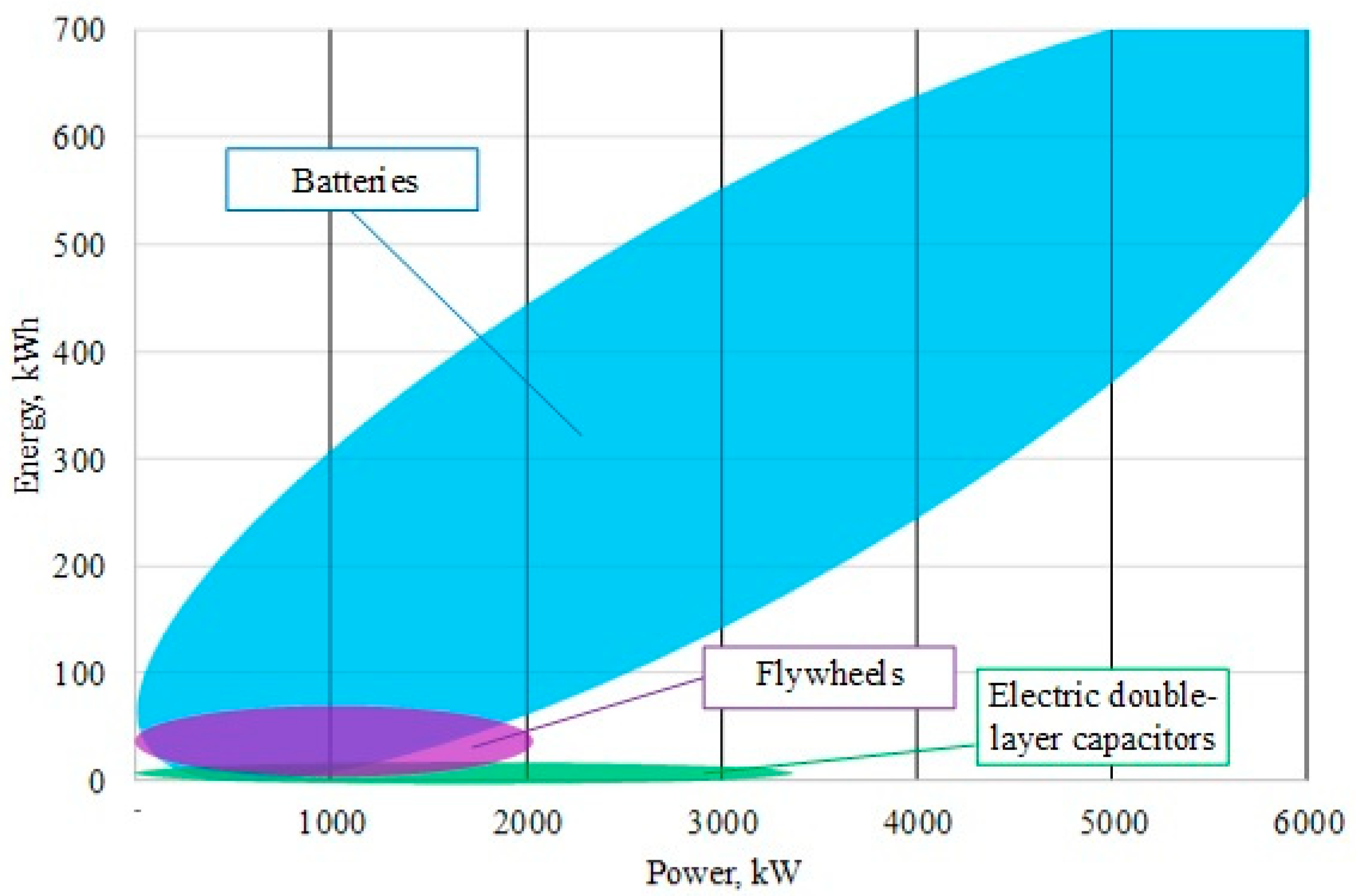
3.1. Types of Storage Systems

3.1.1. Flywheel

Flywheels work by converting electrical energy into kinetic energy from a rotating mass and vice versa. Inertial energy storage contains a body of rotation with a significant moment of inertia—a flywheel. The amount of stored kinetic energy depends on the speed of the rotating mass and the inertia: the higher the speed and the mass of the flywheel, the more rotational energy it can store. Conversion of kinetic energy into electrical energy and vice versa is due to the electrical machine: the rotor shaft is connected to the flywheel shaft. When the energy storage unit is charging, the flywheel is spun up to high speed (less 10,000 revolutions per minute (rpm) for low speed and from 10,000 to 100,000 rpm for high speed) [53]. When the energy storage unit is discharging, the flywheel rotates the shaft of the electric machine until friction losses and the conversion of kinetic energy into electrical energy completely extinguish inertia. This provides continuous flywheel rotation without additional power input and with very low losses.

3.1.2. Electric Double-Layer Capacitors

Unlike conventional capacitors, where the charge is concentrated on the surfaces of the electrodes and the energy of the electric field—in the volume of the interelectrode dielectric, double-layer capacitors are a hybrid of a capacitor and an electrochemical battery. EDLC is an implementation of an idea of the appearance of electrical layers in materials with different types of conductivity (solid and liquid) during their mutual contact proposed in 1879 by Helmholtz. Technical implementation of EDLC comprises a unit cell with two electrodes made of nanoporous carbon materials and a liquid electrolyte, separated by a porous polymer or asbestine separator. This structure actually creates two series-connected supercapacitors: one of the plates corresponding to the electric layer formed in the liquid is virtual from a technical point of view, and the current is collected from the electrical layers formed in the porous electrode; the boundary of the metal/electrolyte thickness of a few nanometers or even fractions of a nanometer is a dielectric. The opposite polarity of the plates in the system of two supercapacitors is formed due to the ion-conducting separator [54].

3.1.3. Electrochemical Energy Storage

The principle of operation of electrochemical energy storage is based on the conversion of electrical energy into chemical energy during charging and vice versa chemical energy into electrical energy during discharge due to a reversible electrochemical reaction.
Electrochemical energy storage usually classifies into primary batteries, secondary batteries, and fuel cells (FC) [55]. Primary and secondary batteries use built-in chemical components, while chemically bound energy of a fuel is provided from the outside for fuel cells. Primary batteries, unlike secondary batteries, cannot be recharged and cannot be called actual energy storage.
Depending on the chemical material used in the electrodes, there is a wide range of secondary electrochemical batteries. Lithium-ion (Li-ion) and nickel-metal hydride (Ni-MH) batteries are the most prevalent types of batteries used in transportation [56].

3.2. Comparison of Energy Storage Types

Comparative characteristics of the considered energy storage types are presented in Table 2. Since the article deals with stationary ESSs, when comparing the technologies under consideration, such indicators as gravimetric and volumetric energy density and power density were not taken into account.
Energy storage for stationary railway applications can be classed into two categories: short-term and long-term, based on storage duration.
The short-term duration category (flywheels and electric double-layer capacitors) typically has a small energy rating and is used in powerful applications—work period is regulated by seconds or minutes—high life cycles, and lifetime as well as high round-trip efficiency. Short-term energy storage is more suitable for high-power applications due to lower capital costs per unit of power.
The long-term duration category (electrochemical batteries and hydrogen FC) can store energy for hours or even days; long-term energy storage is more suitable for high-energy applications due to the relatively low capital cost per unit of energy. However, power capital cost and energy capital cost of Li-ion batteries are practically comparable, which causes a fair explanation for the current broad spectrum of Li-ion battery development and applications. In addition, fast response time provides successful applications in both long-term and short-term categories.
Figure 2 shows fields of application of the different storage techniques in stationary systems deployed at electrified railways according to energy stored and power output. Data based on literary examples of real ESSs. As can be seen from Figure 2, EDLC and flywheels are used for powerful applications with low energy ratings, while batteries have proven successful in both short-term and long-term applications.

3.3. Applications of Energy Storage Systems in Electrified Railway Systems

3.3.1. Regenerative Braking Energy Utilization—Short-Term

The induction motors on a railway vehicle act as generators when braking, converting kinetic energy into electrical energy. The tractive trains and power supply devices in the same supply section utilize the majority of the regenerative braking energy, with the remainder being reinjected into the power grid [61]. Stationary energy storage can recover and release the energy generated from several trains on the line as soon as needed [62]. Energy savings can be up to 45% [63]. The article [64] compares wayside energy storage devices: lead-acid batteries, Ni-MH batteries, Li-ion batteries, supercapacitors, and flywheels in the traction power supply system of the Polish transport company SKM. Supercapacitors are the most cost-effective over a 10-year service life. The article [63] explores different configurations of wayside energy storage application in DC electric rail transportation systems in conditions of maximum regenerative energy saving from trains and minimum capital and operating investment of the storage technologies. It was found that for the purposes of regenerative braking, hybrid ESS based on battery and supercapacitor had the best system performance and indicators for cost-benefit analysis. Practical examples of the use of energy storage for regenerative braking and the effects are shown in Table 3.

3.3.2. Damping of Voltage Fluctuations—Short-Term

The appearance of excess energy during the braking of railway vehicles increases line voltage. The overvoltage can damage electronic equipment, traction, and compressor motors located in the trains and the insulators. It can also cause protection and relays to malfunction and fail [67]. When the power supply is insufficient to satisfy the traction loads demand, the voltage drops significantly. The minimum allowed voltage drop or undervoltage situation in electric railway power systems is 33% [68].
Line voltage instability not only brings various risks to the power system but can result in a power system failure [58]. ESS installed as a stationary system at weak points of the line are expected to reduce line voltage fluctuations. Practical examples of using energy storage devices to reduce voltage drop during network loading are shown in Table 4.

3.3.3. Integration of Renewable Energy System Technologies—Long-Term

The available power of generation systems based on RES, primarily SPPs and wind farms, completely depends on weather conditions and are classified as stochastic generation. Ensuring the balance of active power leads to underutilization of the available power of RES in the case of its surplus or to limitation of the load in case of its deficit. ESS provides the most optimal process for integrating RES into electrified railway systems, allowing the processes of production and consumption of electrical energy to be spaced in time.
Smoothing of the RES output power by ESS is achieved by storing energy during periods of high generation and energy output for use when the RES output power decreases due to weather conditions. In this case, ESS must respond to changes in accordance with the speed of oscillations and have a sufficient supply of energy to operate in the range from several minutes to several hours.
Since the integration of RES into the electrified railway systems requires a long-term application of ESS, batteries and hydrogen FCs are better suited for it, as shown earlier in this review.

4. Hydrogen Technologies

In a number of works devoted to ESSs, FCs are presented as such systems. However, it should be noted that these devices themselves are only capable of producing electricity, not storing it. Therefore, FCs are always used in conjunction with a hydrogen storage system, which is actually an ESS. FCs are currently the most promising and safest devices for generating electricity from hydrogen. Depending on the size and type, they can be used both in “on board” and stationary modes. FCs are notable for their noiseless operation, stability of power generation provided that hydrogen is continuously supplied, and the ability to use one device to produce heat and electricity at the same time [5]. In the case of RE power systems, electricity generated from RE is used for water electrolysis, as a result of which hydrogen is formed. Further, hydrogen is placed in storage, and in case of demand for electricity, it is supplied to the FC. Thus, for the systems considered in this work, hydrogen energy storage consists of three main components: an FC, an electrolyzer, and a hydrogen storage system.

4.1. Hydrogen Energy Storage

4.1.1. Fuel Cells

FC serves as a converter in HRES: electricity is produced in FC during hydrogen oxidation with oxygen from the air. Thus, in fact, if a “direct” reaction of water splitting takes place in an electrolyzer, a “reverse” electrochemical reaction of its formation takes place in an FC. In principle, an FC consists of pipes for supplying and removing gases and water, cathode, anode, and electrolyte.
There are 5 types of hydrogen FCs depending on the electrolyte used: proton exchange membrane (PEMFC), alkali/alkaline anion exchange membrane (AFC/AEMFC), phosphoric acid (PAFC), molten carbonate (MCFC), and solid oxide (SOFC). Some of the main characteristics of these FCs are presented in Table 5.
Since both hydrogen and FCs are not used for continuous power generation, it is low-temperature FCs that are a more suitable option for HRES because they are characterized by quick response and short ramp-up time. In turn, among low-temperature ones, PEMFCs are of greatest interest since, unlike AFCs, they do not contain corrosive medium and can also use air as an oxidizing agent (pure oxygen is required for AFC). Indeed, in the majority of studies on HRES, PEMFCs have been used.
PEMFCs are currently the most used among all FC: according to [71], in 2019, the total installed capacity of PEMFCs reached 934.2 MW. In contrast, for PAFCs, which are next in the rating, the same value was only 106.7 MW. The maximum lifetime of stationary PEMFCs at the moment is about 30,000 h [81]. PEMFC power generation efficiency can be as high as 72% [71] but is typically in the 55–65% range. It should be noted that, according to the authors of [82], it depends on the rated power of an FC: for ones with a capacity of 1–100 kW, it is about 40%, while at a rated power of 1–10 MW, the efficiency of power generation increases to 60%.
It is also important to note that an FC produces heat simultaneously with power. According to the assessment given in [82], the ratio of heat and power produced by an FC (H:P) decreases with an increase in the rated power: from 1 for FCs with a capacity of 1–100 kW to 0.3 for FCs with a capacity of 1–10 MW. However, the generated heat can also be used, for example, for heating water [83,84]. For example, in [84], it is shown that in this case, the total efficiency of an FC increased to 70%, while the efficiency of power generation was 35–50%.

4.1.2. Electrolyzers for Hydrogen Production from Water

The main elements of electrolyzers for producing hydrogen from water are a conductive cap, anode, cathode, electrolyte, and pipes for supplying/removing water, its splitting products (hydrogen, oxygen), and electrolyte. The most widespread now are electrolyzers with concentrated alkali solution electrolytes. However, proton exchange membrane electrolytes are considered as the most suitable alternative, which allows the cell to function at partial load or overload, as well as achieve a higher power density [85,86]. At the moment, alkaline electrolysis is more profitable due to the mature technology; however, in the future, a decrease in the cost and an increase in the efficiency of proton exchange membrane electrolyzers is expected, which could make them even more attractive. So, according to the overview given in [87], the energy consumption of currently commercially available electrolyzers with a proton-exchange membrane is in the range of 4.4–6.5 kW/Nm3 H2. The authors also carried out an analysis of a pilot plant, which showed that at nominal power (5.4 kW/Nm3 H2), the efficiency of an electrolyzer of this type is 56%, including cooling, purification, and compression, and at a lower load (4.7 kW/Nm3 H2) efficiency increased to 64%. Considering this fact, as well as the fact that for safety reasons, the operation of the electrolyzer is not recommended at a load below 15–20% of the rated power, the authors of [8] included in the HRES model from 2 to 34 (depending on the RE source) small electrolyzers with a capacity of 1 kW each instead of a large one. According to the authors, despite the higher cost of such a solution, it will reduce the size of other components of the system (in particular, the hydrogen container and its storage capacity) due to the more stable hydrogen generation. A similar approach was applied in work [88], which is devoted to the optimization of the system “solar panels + membrane electrolyzers” in order to ensure the maximum efficient use of solar energy for hydrogen production. As a result of the study, it was shown that for a system consisting of 4 solar panels with a power of 75 W each and 5 electrolyzers with a power of 50 W each, connected in parallel, the energy transfer was about 95% of the theoretical maximum.
Since both an electrolyzer and an FC are designed in a similar way and can use a proton-exchange membrane as an electrolyte, it is proposed to combine these two devices in one unitized regenerative (reversible) FC (URFC) in order to reduce the cost of an HRES [89]. It also allows making the HRES more compact, which can also be important for using it in small areas.

4.1.3. Hydrogen Storage Systems

Hydrogen has the highest gravimetric energy density in comparison with other fuels, but its volumetric energy density is very low. Thus, the development of compact and safe hydrogen storage is one of the key problems of the hydrogen economy.
In Table 6 advantages and disadvantages of different types of hydrogen storage systems are presented. It should be noted that, despite the shortcomings, each of the systems can be used in a specific area.

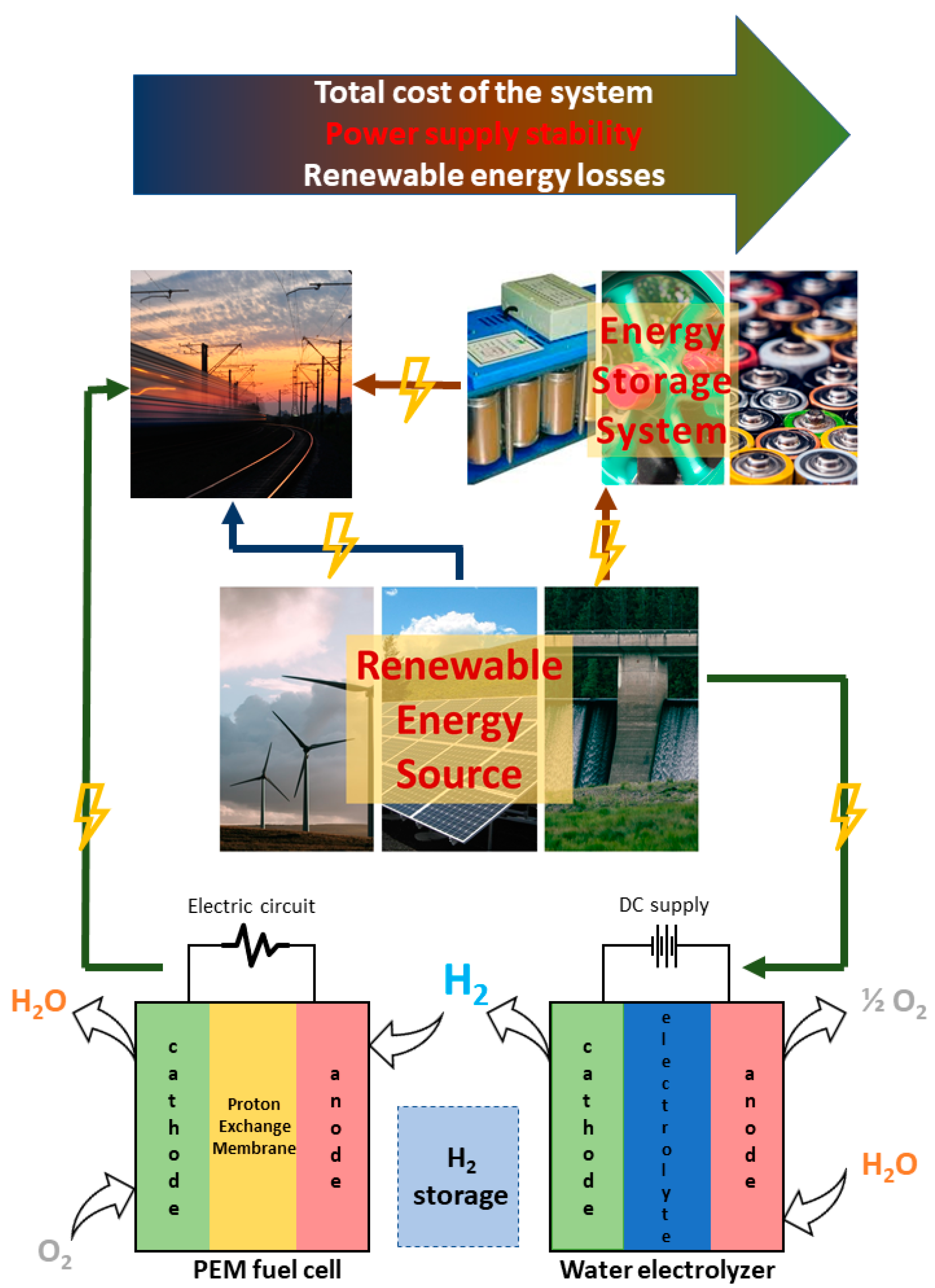
4.2. Application of Hydrogen Technologies for Hybrid Power Systems

At the moment, there are few real HRES projects similar to the ones described above; however, not a single case with their use on the railway has been found. For example, a system consisting of solar panels (2 kW), a lead-acid battery (48 V/300 A∙h), an alkaline electrolyzer (0.5 Nm3 H2/h), a PEMFC (200 W), and a hydrogen storage system based on the LaNi5 alloy (10 Nm3) functioned for several months in China [91]. It has been shown that about 45% of solar energy is stored in the form of hydrogen in such a plant. Unfortunately, due to the low efficiency of solar panels, the total efficiency of the power plant was only 4%. This value is 2 times higher for a similar power plant PHOEBUS, which operated in Germany for 10 years [92]. It has been demonstrated that at low insolation, 50–52% of the total electricity demand was delivered by the battery, while 20–25% was supplied by the FC. As a result of the project, the authors concluded that the most stable and efficient power supply could be provided by systems with low-capacity batteries in combination with hydrogen.
Also, in the literature, the results of HRES modeling for certain areas are presented. So, for example, in [8], an HRES simulation for various types of RE (solar, wind, hydro-power) is presented. Calculations have shown that for mountainous country in Italy, the HRES with a micro-hydro turbine is the best choice. The efficiency of such a system, which, in addition to a micro-hydro turbine, consists of electrolyzers, a PEMFC, a battery, and a hydrogen storage system, was 36.5%. While when using solar or wind energy, it dropped to 4.7 or 7.1, respectively. It should be noted that in the case of micro-hydro turbine, the largest amount of energy (30.2% of the power from RES) was sent directly to the consumer; in contrast, in the case of solar panels and WTs, 20.2% and 9.2% of the generated energy was directly used, respectively. For all RES, the authors have shown that PEMFCs produce 38% of the input energy sent to the electrolyzer. It is noted that this value is higher for batteries, but they are not suitable for long-term seasonal energy storage. For Newfoundland, modeling was also made for various HRES using wind energy [93]. It was shown that a system consisting of a wind generator, an FC (3.5 kW), a converter (3.5 kW), an electrolyzer (7.5 kW), and a hydrogen storage system with a capacity of 10 kg could be the best choice for use if it were not for the high cost of FCs.
Since the power generation from renewable sources often cannot be constant and depends on both the time of day and the season, several sources can be used simultaneously to increase stability. For example, in [94], the HRES used a 10 kW wind turbine and a 1 kW solar panel. Combined with PEMFC (5 kW), this system provides high stability in power generation.
For transport, including railway, it is also a possible scenario when electricity from renewable sources is used to produce hydrogen in a stationary installation, while PEMFC and a battery (PEMFC provide a constant average power, while the batteries meet power peaks [95]) installed directly on board the vehicle. Thus, a hydrogen refueling infrastructure can be formed. A similar system using a WT is proposed in [96]—it is shown that it is suitable for use in rail transport in Berlin and Brandenburg.
Thus, 3 ways of using RE to power a grid can be defined (Figure 3):
  • The generated electricity through the converter is fed directly to the grid (blue arrows);
  • The generated electricity is stored in an energy storage device and then, on-demand, is supplied to the grid (brown arrows);
  • The generated electricity is used to produce hydrogen by water electrolysis; when the need for electricity arises, hydrogen from the hydrogen storage system is supplied to the FC, where electricity is generated, which is fed to the grid (green arrows).
Option 2 looks like the easiest way to provide relatively stable power to the grid from a RE source. However, it has been shown [97,98,99,100,101] that it is the combination of a “physical” energy storage (battery, for example) device and hydrogen that is the most economically viable for use in hybrid power plants based on RE. In addition, it allows for better stability compared to a situation where only one type of ESS is used, which is of particular importance for railway electrification. On the other hand, the total cost of a system, as well as renewable energy losses, increase with the integration of hydrogen energy storage in a system. Therefore, these problems remain challenging and are to be solved in future studies.

5. Conclusions

Renewable energy sources are increasingly being introduced into all sectors of the economy, and rail transport is no exception. To date, engineers from different countries have already developed and continue to develop many technical solutions based on renewable energy sources and energy storage systems to improve the efficiency and environmental friendliness of railway transport.
  • The analysis of the publications allowed defining the main groups of technical solutions for the integration of renewable energy systems into the railway infrastructure. Their advantages and disadvantages were described. Examples of the implementation of these systems in various countries were given. The analysis identified the main criteria for the feasibility of using various options for renewable energy systems at the design stage.
  • Various types of energy storage systems that play a key role in integrating renewable energy with rail electrification systems were also considered. A comparative analysis of the technical and economic characteristics of various types of storage devices has been carried out.
  • In this review, special attention was paid to works describing the configuration of hybrid energy storage systems based on hydrogen storage, electrochemical storage batteries, and supercapacitors. Optimally selected characteristics of the storage system make it possible to compensate for the shortcomings of each individual element, providing both high-speed performance and high peak power values in the event of sudden changes in the mode, and a large capacity of stored energy, which allows using renewable energy systems with maximum efficiency.
  • The analysis of publications showed that at present, the greatest interest from researchers is shown to hybrid microgrid systems, which include various generation systems based on renewable energy sources, as well as energy storage systems of various types. This option is the most effective from the standpoint of reliability and quality of power supply since it reduces the likelihood of imbalances between the generation and consumption of electrical energy caused by the variable operating mode and significant fluctuations in the output power of renewable energy systems.
Summing up, we can say that today modern technologies based on renewable energy sources and energy storage systems have found their application in the electrification of railway transport and the current trend towards the development of “green” technologies will lead in the future to a significant increase in the share of renewable energy in this industry.

Funding

The reported study was funded by RFBR, Sirius University of Science and Technology, JSC Russian Railways and Educational Fund “Talent and success”, project number 20-38-51007.

Acknowledgments

The authors thank student Karina Matseruk for the help in the preparation of the manuscript and Pavel V. Matrenin for valuable comments.

Conflicts of Interest

The authors declare no conflict of interest. The funders had no role in the design of the study; in the collection, analyses, or interpretation of data; in the writing of the manuscript, or in the decision to publish the results.

References

  1. Strategiya Nauchno-Tekhnologicheskogo Razvityia Kholdinga “RZhD” na Period do 2020 goda i na Perspectivu do 2025 goda (Belaya Kniga); JSC Russian Railways: Moscow, Russia, 2018; (In Russian). Available online: http://www.rzd-expo.ru/innovation/BelKniga_2015.pdf (accessed on 14 September 2021).
  2. The State of the Global Renewable Energy Transition. Highlights of the REN21 Renewables 2018 Global Status Report in Perspective. Renewable Energy Policy Network for the 21st Century (REN21). 2018. 52p. Available online: https://www.ren21.net/wp-content/uploads/2019/05/GSR2018_Highlights_English.pdf (accessed on 14 September 2021).
  3. Al’ternativnaya Energetika na Zheleznodorozhnom Transporte Indii; Center of Scientific-Technical Information and Libraries—JSC Russian Railways Branch: Moscow, Russia, 2021; (In Russian). Available online: https://lib.rgups.ru/site/assets/files/1207/al_ternativnaia_energetika_na_zheleznodorozhnom_transporte_indii.pdf (accessed on 14 September 2021).
  4. Singh, A. Indian Railways Power house of India. Zenodo 2019. Available online: https://zenodo.org/record/2598043#.YUPzebgzaUk (accessed on 14 September 2021). [CrossRef]
  5. Cigolotti, V.; Genovese, M.; Fragiacomo, P. Comprehensive Review on Fuel Cell Technology for Stationary Applications as Sustainable and Efficient Poly-Generation Energy Systems. Energies 2021, 14, 4963. [Google Scholar] [CrossRef]
  6. Jiao, K.; Xuan, J.; Du, Q.; Bao, Z.; Xie, B.; Wang, B.; Zhao, Y.; Fan, L.; Wang, H.; Hou, Z.; et al. Designing the next generation of proton-exchange membrane fuel cells. Nature 2021, 595, 361–369. [Google Scholar] [CrossRef]
  7. International Energy Agency. Technology Roadmap: Hydrogen and Fuel Cells; International Energy Agency: Paris, France, 2015; Available online: https://www.iea.org/reports/technology-roadmap-hydrogen-and-fuel-cells (accessed on 14 September 2021).
  8. Santarelli, M.; Call, M.; Macagno, S. Design and analysis of stand-alone hydrogen energy systems with different renewable sources. Int. J. Hydrogen Energy 2004, 29, 1571–1586. [Google Scholar] [CrossRef]
  9. Kameya, T.; Katsuma, H.; Suzuki, G.; Harada, Y. Proposal of LRT Using Renewable Energy. In Proceedings of the 30th ISES Biennial Solar World Congress, Kassel, Germany, 28 August–2 September 2011; pp. 1–7. [Google Scholar] [CrossRef]
  10. Korfiati, A.; Gkonos, C.; Veronesi, F.; Gaki, A.; Grassi, S.; Schenkel, R.; Volkwein, S.; Raubal, M.; Hurni, L. Estimation of the Global Solar Energy Potential and Photovoltaic Cost with the use of Open Data. Int. J. Sustain. Energy Plan. Manag. 2016, 9, 17–30. [Google Scholar] [CrossRef]
  11. International Union of Railways. Technologies and Potential Developments for Energy Efficiency and CO2 Reductions in Rail Systems; International Union of Railways: Paris, France, 2016. [Google Scholar]
  12. Rohollahi, E.; Abdolzadeh, M.; Mehrabian, M.A. Prediction of the power generated by photovoltaic cells fixed on the roof of a moving passenger coach: A case study. Proc. Inst. Mech. Eng. Part F J. Rail Rapid Transit 2014, 229, 830–837. [Google Scholar] [CrossRef]
  13. Darshana, M.K.; Karnataki, K.; Shankar, G.; Sheela, K.R. A practical implementation of energy harvesting, monitoring and analysis system for solar photo voltaic terrestrial vehicles in Indian scenarios: A case of pilot implementation in the Indian Railways. In Proceedings of the 2015 IEEE International WIE Conference on Electrical and Computer Engineering (WIECON-ECE), Dhaka, Bangladesh, 19–20 December 2015; pp. 542–545. [Google Scholar] [CrossRef]
  14. Vasisht, S.M.; Vishal, C.; Srinivasan, J.; Ramasesha, S.K. Solar photovoltaic assistance for LHB rail coaches. Curr. Sci. 2014, 107, 255–258. [Google Scholar] [CrossRef]
  15. Vasisht, M.S.; Vashista, G.; Srinivasan, J.; Ramasesha, S.K. Rail coaches with rooftop solar photovoltaic systems: A feasibility study. Energy 2017, 118, 684–691. [Google Scholar] [CrossRef]
  16. Gangwar, M.; Sharma, S.M. Evaluating choice of traction option for a sustainable Indian Railways. Transp. Res. Part D Transp. Environ. 2014, 33, 135–145. [Google Scholar] [CrossRef]
  17. Thelkar, A.R.; Veerasamy, B.; Mekonnen, T.; Ahmmed, M.; Alem, A.; Jote, A. Interfacing of regulator and rectifier unit with solar charge controller for optimal utilization of solar power on railway coaches. In Proceedings of the 2016 IEEE International Conference on Renewable Energy Research and Applications (ICRERA), Birmingham, UK, 20–23 November 2016; pp. 730–735. [Google Scholar] [CrossRef]
  18. Omar, W.A.W.; Hayder, G.; Aldrees, A.; Taha, A.T.B. Feasibility study on use of solar energy in Malaysia’s light rail transit. IOP Conf. Ser. Earth Environ. Sci. 2021, 708. [Google Scholar] [CrossRef]
  19. Srivastava, A.; Singh, A.; Joshi, G.; Gupta, A. Utilization of wind energy from railways using vertical axis wind turbine. In Proceedings of the 2015 International Conference on Energy Economics and Environment (ICEEE), Greater Noida, India, 27–28 March 2015; pp. 1–5. [Google Scholar]
  20. Bharech, S.; Singhal, D. Development of a model to convert wind energy of a speeding locomotive into electrical energy. In Proceedings of the 1st National Convention of Electrical Engineers & National Seminar on Renewable Energy and Green Technology for Sustainable Development, Bhopal, India, 17–18 October 2015. [Google Scholar]
  21. Mishra, A.; Ashhad, F. A Concept for Wind power Generated in High Speed Luxury Trains. Int. J. Appl. Eng. Res. 2019, 14, 38–42. [Google Scholar]
  22. Prasanth, G.; Sudheshnan, T. A renewable energy approach by fast moving vehicles. In Proceedings of the National Seminar & Exhibition on Non-Destructive Evaluation, Tirupur, India, 8–10 December 2011; pp. 232–236. [Google Scholar]
  23. Zulu, J.; Lencwe, M.J.; Chowdhury, S.P.D. Green Energy for railway train mounted Wind Generator. In Proceedings of the 10th International Renewable Energy Congress (IREC), Sousse, Tunisia, 26–28 March 2019; pp. 1–6. [Google Scholar]
  24. Nurmanova, V.; Bagheri, M.; Sultanbek, A.; Hekmati, A.; Bevrani, H. Feasibility study on wind energy harvesting system implementation in moving trains. In Proceedings of the 2017 International Siberian Conference on Control and Communications (SIBCON), Astana, Kazakhstan, 29–30 June 2017; pp. 1–6. [Google Scholar]
  25. Kumar, A.; Karandikar, P.B.; Chavan, D.S. Generating and saving energy by installing wind turbines along the railway tracks. In Proceedings of the 2015 International Conference on Energy Systems and Applications, Pune, India, 30 October–1 November 2015; pp. 25–27. [Google Scholar]
  26. Oñederra, O.; Asensio, F.J.; Saldaña, G.; Martín, J.I.S.; Zamora, I. Wind Energy Harnessing in a Railway Infrastructure: Converter Topology and Control Proposal. Electronics 2020, 9, 1943. [Google Scholar] [CrossRef]
  27. Asensio, F.J.; Martin, J.I.S.; Zamora, I.; Oñederra, O.; Saldaña, G.; Eguia, P. A system approach to harnessing wind energy in a railway infrastructure. In Proceedings of the IECON 2018–44th Annual Conference of the IEEE Industrial Electronics Society, Washington, DC, USA, 21–23 October 2018; pp. 1646–1651. [Google Scholar] [CrossRef]
  28. Pan, H.; Li, H.; Zhang, T.; Laghari, A.A.; Zhang, Z.; Yuan, Y.; Qian, B. A portable renewable wind energy harvesting system integrated S-rotor and H-rotor for self-powered applications in high-speed railway tunnels. Energy Convers. Manag. 2019, 196, 56–68. [Google Scholar] [CrossRef]
  29. Chen, Y.; Chen, M.; Liu, Y.; Chen, L. Analysing the Voltage Unbalance Impact of Wind Farm on Traction Power Supply System. In Proceedings of the 2019 14th IEEE Conference on Industrial Electronics and Applications (ICIEA), Xi’an, China, 19–21 June 2019; pp. 1557–1561. [Google Scholar] [CrossRef]
  30. Ding, F.; Zhang, D.; He, J.; Liu, H.; Li, Y. Evaluation of the influence of electrified railway on wind farm. In Proceedings of the 2017 IEEE Transportation Electrification Conference and Expo, Asia-Pacific (ITEC Asia-Pacific), Harbin, China, 7–10 August 2017; pp. 1–6. [Google Scholar] [CrossRef]
  31. Zhang, G.F.; Li, S.H.; Sun, F.; Bai, X.; Cheng, X.K. Power Quality Evaluation of Electrified Railway’s Impact on Wind Farm Electric and Its Engineering Application. J.Phys. Conf. Ser. 2018, 1087, 042066. [Google Scholar] [CrossRef]
  32. Energy Charter Secretariat. In-Depth Review of Energy Efficiency Policies and Programmes; Energy Charter Secretariat: Mongolia, 2011; ISBN 9789059480926. Available online: https://www.energycharter.org/what-we-do/energy-efficiency/energy-efficiency-country-reviews/in-depth-review-of-energy-efficiency-policies-and-programmes/ (accessed on 14 September 2021).
  33. Ji, L.; Ning, F.; Ma, J.; Jia, L. SWOT analysis for orchestrated development of a solar railway system in China. IET Renew. Power Gener. 2020, 14, 3628–3635. [Google Scholar] [CrossRef]
  34. Shen, X.; Zhang, Y.; Chen, S. Investigation of grid-connected photovoltaic generation system applied for Urban Rail Transit energy-savings. In Proceedings of the 2012 IEEE Industry Applications Society Annual Meeting, Las Vegas, NV, USA, 7–11 October 2012; pp. 1–4. [Google Scholar] [CrossRef]
  35. Sengor, I.; Kilickiran, H.C.; Akdemir, H.; Kekezoglu, B.; Erdinc, O.; Catalao, J.P.S. Energy Management of a Smart Railway Station Considering Regenerative Braking and Stochastic Behaviour of ESS and PV Generation. IEEE Trans. Sustain. Energy 2017, 9, 1041–1050. [Google Scholar] [CrossRef]
  36. Pankovits, P.; Pouget, J.; Robyns, B.; Delhaye, F.; Brisset, S. Towards railway-smartgrid: Energy management optimization for hybrid railway power substations. In Proceedings of the IEEE PES Innovative Smart Grid Technologies, Europe, Istanbul, Turkey, 12–15 October 2014; pp. 1–6. [Google Scholar] [CrossRef]
  37. Jaffery, S.H.I.; Khan, H.A.; Khan, M.; Ali, S. A study on the feasibility of solar powered railway system for light weight urban transport. In Proceedings of the World Renewable Energy Forum, Denver, CO, USA, 13–17 May 2012; pp. 1892–1896. [Google Scholar]
  38. Jaffery, S.H.I.; Khan, M.; Ali, L.; Khan, H.; Mufti, R.A.; Khan, A.; Khan, N. The potential of solar powered transportation and the case for solar powered railway in Pakistan. Renew. Sustain. Energy Rev. 2014, 39, 270–276. [Google Scholar] [CrossRef]
  39. Patil, T.D.; Patil, K.D.; Mahajan, S.M. Efficient Use of Renewable Energy in Train and Railway Station. Int. J. Innov. Technol. Explor. Eng. 2014, 3, 18–22. [Google Scholar]
  40. Jia, L.; Ma, J.; Cheng, P.; Liu, Y. A perspective of solar energy-powered road and rail transportation in China. CSEE J. Power Energy Syst. 2020, 6, 760–771. [Google Scholar] [CrossRef]
  41. Hayashiya, H.; Itagaki, H.; Morita, Y.; Mitoma, Y.; Furukawa, T.; Kuraoka, T.; Fukasawa, Y.; Oikawa, T. Potentials, peculiarities and prospects of solar power generation on the railway premises. In Proceedings of the 2012 International Conference on Renewable Energy Research and Applications (ICRERA), Nagasaki, Japan, 11–14 November 2012; pp. 1–6. [Google Scholar]
  42. Morita, Y.; Honda, M.; Kuraoka, T.; Fukasawa, Y.; Mitoma, Y.; Yoshizumi, H.; Hayashiya, H. Analysis of local smoothing effect on the PV on Tokyo station. In Proceedings of the 2012 International Conference on Renewable Energy Research and Applications (ICRERA), Nagasaki, Japan, 11–14 November 2012; pp. 1–6. [Google Scholar]
  43. Nazir, C.P. Solar Energy for Traction of High Speed Rail Transportation: A Techno-economic Analysis. Civ. Eng. J. 2019, 5, 1566–1576. [Google Scholar] [CrossRef] [Green Version]
  44. Zhou, X. A Study on Potential for Using New Energy and Renewable Energy Sources in Railways. Int. J. Energy Power Eng. 2019, 8, 45. [Google Scholar] [CrossRef] [Green Version]
  45. Ostapchuk, O.; Kuznietsov, M.; Kuznetsov, V.; Kuznetsov, V. Problems of the use of renewable energy sources in the structure of railway power supply. IOP Conf. Ser. Mater. Sci. Eng. 2020, 985, 012011. [Google Scholar] [CrossRef]
  46. Pankovits, P.; Ployard, M.; Pouget, J.; Brisset, S.; Abbes, D.; Robyns, B. Design and operation optimization of a hybrid railway power substation. In Proceedings of the 2013 15th European Conference on Power Electronics and Applications (EPE), Lille, France, 2–6 September 2013; pp. 1–8. [Google Scholar]
  47. Aguado, J.A.; Racero, A.J.S.; De La Torre, S. Optimal Operation of Electric Railways With Renewable Energy and Electric Storage Systems. IEEE Trans. Smart Grid 2016, 9, 993–1001. [Google Scholar] [CrossRef]
  48. Boudoudouh, S.; Maaroufi, M. Renewable Energy Sources Integration and Control in Railway Microgrid. IEEE Trans. Ind. Appl. 2018, 55, 2045–2052. [Google Scholar] [CrossRef]
  49. Nasr, S.; Iordache, M.; Petit, M. Smart micro-grid integration in DC railway systems. In Proceedings of the IEEE PES Innovative Smart Grid Technologies, Europe, Istanbul, Turkey, 12–15 October 2014; pp. 1–6. [Google Scholar] [CrossRef]
  50. Perez, F.; Iovine, A.; Damm, G.; Galai-Dol, L.; Ribeiro, P.F. Stability Analysis of a DC MicroGrid for a Smart Railway Station Integrating Renewable Sources. IEEE Trans. Control. Syst. Technol. 2019, 28, 1802–1816. [Google Scholar] [CrossRef]
  51. Jamal, T.; Salehin, S. Hybrid renewable energy sources power systems. Hybrid Renew. Energy Syst. Microgrids 2021, 179–214. Available online: https://www.sciencedirect.com/science/article/pii/B9780128217245000106?via%3Dihub (accessed on 14 September 2021). [CrossRef]
  52. Ghaviha, N.; Campillo, J.; Bohlin, M.; Dahlquist, E. Review of Application of Energy Storage Devices in Railway Transportation. Energy Procedia 2017, 105, 4561–4568. [Google Scholar] [CrossRef]
  53. Olabi, A.; Wilberforce, T.; Abdelkareem, M.; Ramadan, M. Critical Review of Flywheel Energy Storage System. Energies 2021, 14, 2159. [Google Scholar] [CrossRef]
  54. Sharma, P.; Bhatti, T. A review on electrochemical double-layer capacitors. Energy Convers. Manag. 2010, 51, 2901–2912. [Google Scholar] [CrossRef]
  55. Buckley, D.N.; O’Dwyer, C.; Quill, N.; Lynch, R.P. Electrochemical Energy Storage. In Energy Storage Options and Their Environmental Impact; The Royal Society of Chemistry: Croydon, UK, 2019; pp. 115–149. ISBN 978-1-78801-399-4. Available online: https://pubs.rsc.org/en/content/chapter/bk9781788013994-00115/978-1-78801-399-4 (accessed on 14 September 2021).
  56. Ratniyomchai, T.; Hillmansen, S.; Tricoli, P. Recent developments and applications of energy storage devices in electrified railways. IET Electr. Syst. Transp. 2014, 4, 9–20. [Google Scholar] [CrossRef]
  57. Hossain, E.; Faruque, H.; Sunny, S.H.; Mohammad, N.; Nawar, N. A Comprehensive Review on Energy Storage Systems: Types, Comparison, Current Scenario, Applications, Barriers, and Potential Solutions, Policies, and Future Prospects. Energies 2020, 13, 3651. [Google Scholar] [CrossRef]
  58. Liu, X.; Li, K. Energy storage devices in electrified railway systems: A review. Transp. Saf. Environ. 2020, 2, 183–201. [Google Scholar] [CrossRef]
  59. Meishner, F.; Sauer, D.U. Wayside energy recovery systems in DC urban railway grids. eTransportation 2019, 1, 100001. [Google Scholar] [CrossRef]
  60. Okui, A.; Hase, S.; Shigeeda, H.; Konishi, T.; Yoshi, T. Application of energy storage system for railway transportation in Japan. In Proceedings of the The 2010 International Power Electronics Conference-ECCE ASIA, Sapporo, Japan, 21–24 June 2010; pp. 3117–3123. [Google Scholar]
  61. Chen, J.; Hu, H.; Ge, Y.; Wang, K.; Huang, W.; He, Z. An Energy Storage System for Recycling Regenerative Braking Energy in High-Speed Railway. IEEE Trans. Power Deliv. 2020, 36, 320–330. [Google Scholar] [CrossRef]
  62. Cipolletta, G.; Femine, A.D.; Gallo, D.; Luiso, M.; Landi, C. Design of a Stationary Energy Recovery System in Rail Transport. Energies 2021, 14, 2560. [Google Scholar] [CrossRef]
  63. Dutta, O.; Saleh, M.; Khodaparastan, M.; Mohamed, A. A Dual-Stage Modeling and Optimization Framework for Wayside Energy Storage in Electric Rail Transit Systems. Energies 2020, 13, 1614. [Google Scholar] [CrossRef] [Green Version]
  64. Radu, P.V.; Drazek, Z. Analysis of wayside energy storage devices for DC heavy rail transport. MATEC Web Conf. 2018, 180. [Google Scholar] [CrossRef] [Green Version]
  65. Radcliffe, P.; Wallace, J.S.; Shu, L.H. Stationary applications of energy storage technologies for transit systems. In Proceedings of the 2010 IEEE Electrical Power & Energy Conference, Halifax, NS, Canada, 25–27 August 2010; pp. 1–7. [Google Scholar]
  66. Hayashiya, H.; Hara, D.; Tojo, M.; Watanabe, K.; Hino, M.; Suzuki, T.; Okamoto, H.; Takahashi, H.; Kato, T.; Teshima, M. Lithium-ion battery installation in traction power supply system for regenerative energy utilization: Initial report of effect evaluation after half a year operation. In Proceedings of the 2014 16th International Power Electronics and Motion Control Conference and Exposition, Antalya, Turkey, 21–24 September 2014; pp. 119–124. [Google Scholar] [CrossRef]
  67. Kaleybar, H.J.; Brenna, M.; Foiadelli, F.; Fazel, S.S.; Zaninelli, D. Power Quality Phenomena in Electric Railway Power Supply Systems: An Exhaustive Framework and Classification. Energies 2020, 13, 6662. [Google Scholar] [CrossRef]
  68. Brenna, M.; Foiadelli, F.; Zaninelli, D. DC Railway Electrification Systems. In Electrical Railway Transportation Systems; Wiley-IEEE Press: Hoboken, NJ, USA, 2018; pp. 99–176. [Google Scholar] [CrossRef]
  69. Lamedica, R.; Ruvio, A.; Galdi, V.; Graber, G.; Sforza, P.; GuidiBuffarini, G.; Spalvieri, C. Application of battery auxiliary substations in 3kV railway systems. In Proceedings of the 2015 AEIT International Annual Conference (AEIT), Naples, Italy, 14–16 October 2015; pp. 1–6. [Google Scholar]
  70. Lee, H.; Kim, G.; Lee, C.; Joung, E. Field Tests of DC 1500 V Stationary Energy Storage System. Int. J. Railw. 2012, 5, 124–128. [Google Scholar] [CrossRef]
  71. Wang, Y.; Seo, B.; Wang, B.; Zamel, N.; Jiao, K.; Adroher, X.C. Fundamentals, materials, and machine learning of polymer electrolyte membrane fuel cell technology. Energy AI 2020, 1, 100014. [Google Scholar] [CrossRef]
  72. Ferriday, T.; Middleton, P.H. Alkaline fuel cell technology—A review. Int. J. Hydrogen Energy 2021, 46, 18489–18510. [Google Scholar] [CrossRef]
  73. Ramadhani, F.; Hussain, M.A.; Mokhlis, H. A Comprehensive Review and Technical Guideline for Optimal Design and Operations of Fuel Cell-Based Cogeneration Systems. Processes 2019, 7, 950. [Google Scholar] [CrossRef] [Green Version]
  74. Wee, J.-H. Carbon dioxide emission reduction using molten carbonate fuel cell systems. Renew. Sustain. Energy Rev. 2014, 32, 178–191. [Google Scholar] [CrossRef]
  75. Leo, T. Molten Carbonate Fuel Cells: Theory and Application. Compr. Renew. Energy 2012, 4, 247–259. [Google Scholar] [CrossRef]
  76. Cassir, M.; Ringuedé, A.; Lair, V. Molten Carbonates from Fuel Cells to New Energy Devices. In Molten Salts Chemistry; Elsevier: Burlington, VT, USA, 2013; pp. 355–371. Available online: https://www.sciencedirect.com/science/article/pii/B9780123985385000172?via%3Dihub (accessed on 14 September 2021). [CrossRef]
  77. Kirubakaran, A.; Jain, S.; Nema, R. A review on fuel cell technologies and power electronic interface. Renew. Sustain. Energy Rev. 2009, 13, 2430–2440. [Google Scholar] [CrossRef]
  78. Singh, M.; Zappa, D.; Comini, E. Solid oxide fuel cell: Decade of progress, future perspectives and challenges. Int. J. Hydrogen Energy 2021, 46, 27643–27674. [Google Scholar] [CrossRef]
  79. Park, E.D.; Lee, D.; Lee, H.C. Recent progress in selective CO removal in a H2-rich stream. Catal. Today 2009, 139, 280–290. [Google Scholar] [CrossRef]
  80. Miyaoka, H.; Miyaoka, H.; Ichikawa, T.; Ichikawa, T.; Kojima, Y. Highly purified hydrogen production from ammonia for PEM fuel cell. Int. J. Hydrogen Energy 2018, 43, 14486–14492. [Google Scholar] [CrossRef]
  81. Li, B.; Roche, R.; Miraoui, A. Microgrid sizing with combined evolutionary algorithm and MILP unit commitment. Appl. Energy 2017, 188, 547–562. [Google Scholar] [CrossRef] [Green Version]
  82. Bauen, A.; Hart, D.; Chase, A. Fuel cells for distributed generation in developing countries—An analysis. Int. J. Hydrogen Energy 2003, 28, 695–701. [Google Scholar] [CrossRef]
  83. Facci, A.L.; Ubertini, S. Analysis of a fuel cell combined heat and power plant under realistic smart management scenarios. Appl. Energy 2018, 216, 60–72. [Google Scholar] [CrossRef]
  84. Shabani, B.; Andrews, J. An experimental investigation of a PEM fuel cell to supply both heat and power in a solar-hydrogen RAPS system. Int. J. Hydrogen Energy 2011, 36, 5442–5452. [Google Scholar] [CrossRef]
  85. Götz, M.; Lefebvre, J.; Mörs, F.; Koch, A.M.; Graf, F.; Bajohr, S.; Reimert, R.; Kolb, T. Renewable Power-to-Gas: A technological and economic review. Renew. Energy 2016, 85, 1371–1390. [Google Scholar] [CrossRef] [Green Version]
  86. Parra, D.; Patel, M.K. Techno-economic implications of the electrolyser technology and size for power-to-gas systems. Int. J. Hydrogen Energy 2016, 41, 3748–3761. [Google Scholar] [CrossRef]
  87. Buttler, A.; Spliethoff, H. Current status of water electrolysis for energy storage, grid balancing and sector coupling via power-to-gas and power-to-liquids: A review. Renew. Sustain. Energy Rev. 2018, 82, 2440–2454. [Google Scholar] [CrossRef]
  88. Paul, B.; Andrews, J. Optimal coupling of PV arrays to PEM electrolysers in solar–hydrogen systems for remote area power supply. Int. J. Hydrogen Energy 2008, 33, 490–498. [Google Scholar] [CrossRef]
  89. Pu, Z.; Zhang, G.; Hassanpour, A.; Zheng, D.; Wang, S.; Liao, S.; Chen, Z.; Sun, S. Regenerative fuel cells: Recent progress, challenges, perspectives and their applications for space energy system. Appl. Energy 2020, 283, 116376. [Google Scholar] [CrossRef]
  90. Moradi, R.; Groth, K.M. Hydrogen storage and delivery: Review of the state of the art technologies and risk and reliability analysis. Int. J. Hydrogen Energy 2019, 44, 12254–12269. [Google Scholar] [CrossRef]
  91. Liu, Z.; Qiu, Z.; Luo, Y.; Mao, Z.; Wang, C. Operation of first solar-hydrogen system in China. Int. J. Hydrogen Energy 2010, 35, 2762–2766. [Google Scholar] [CrossRef]
  92. Ghosh, P.C.; Emonts, B.; Janßen, H.; Mergel, J.; Stolten, D. Ten years of operational experience with a hydrogen-based renewable energy supply system. Sol. Energy 2003, 75, 469–478. [Google Scholar] [CrossRef]
  93. Khan, M.J.; Iqbal, M.T. Pre-feasibility study of stand-alone hybrid energy systems for applications in Newfoundland. Renew. Energy 2005, 30, 835–854. [Google Scholar] [CrossRef]
  94. Agbossou, K.; Chahine, R.; Hamelin, J.; Laurencelle, F.; Anouar, A.; St-Arnaud, J.-M.; Bose, T.K. Renewable energy systems based on hydrogen for remote applications. J. Power Sources 2001, 96, 168–172. [Google Scholar] [CrossRef]
  95. Zenith, F.; Isaac, R.; Hoffrichter, A.; Thomassen, M.S.; Møller-Holst, S. Techno-economic analysis of freight railway electrification by overhead line, hydrogen and batteries: Case studies in Norway and USA. Proc. Inst. Mech. Eng. Part. F J. Rail Rapid Transit 2019, 234, 791–802. [Google Scholar] [CrossRef] [Green Version]
  96. Herwartz, S.; Pagenkopf, J.; Streuling, C. Sector coupling potential of wind-based hydrogen production and fuel cell train operation in regional rail transport in Berlin and Brandenburg. Int. J. Hydrogen Energy 2021, 46, 29597–29615. [Google Scholar] [CrossRef]
  97. Dong, W.; Li, Y.; Xiang, J. Optimal Sizing of a Stand-Alone Hybrid Power System Based on Battery/Hydrogen with an Improved Ant Colony Optimization. Energies 2016, 9, 785. [Google Scholar] [CrossRef]
  98. Dawood, F.; Shafiullah, G.M.; Anda, M. Stand-Alone Microgrid with 100% Renewable Energy: A Case Study with Hybrid Solar PV-Battery-Hydrogen. Sustainability 2020, 12, 2047. [Google Scholar] [CrossRef] [Green Version]
  99. Li, C.-H.; Zhu, X.-J.; Cao, G.-Y.; Sui, S.; Hu, M.-R. Dynamic modeling and sizing optimization of stand-alone photovoltaic power systems using hybrid energy storage technology. Renew. Energy 2009, 34, 815–826. [Google Scholar] [CrossRef]
  100. Nordin, N.D.; Rahman, H.A. Comparison of optimum design, sizing, and economic analysis of standalone photovoltaic/battery without and with hydrogen production systems. Renew. Energy 2019, 141, 107–123. [Google Scholar] [CrossRef]
  101. Marocco, P.; Ferrero, D.; Lanzini, A.; Santarelli, M. Optimal design of stand-alone solutions based on RES + hydrogen storage feeding off-grid communities. Energy Convers. Manag. 2021, 238, 114147. [Google Scholar] [CrossRef]
Figure 1. RE sources classification for the railway transport electrification systems.
Energies 14 05946 g001
Figure 2. Power rating and energy capacity of different stationary (wayside) ESSs for electrified railway systems (data based on references [56,59,60]).
Energies 14 05946 g002
Figure 3. Scheme of the railway electrification by means of RES.
Energies 14 05946 g003
Table 1. Summary table of RE technologies in railway transport.
FactorOption Number
12345678
Power range, kW0.1–1.50.4–100100–1 × 1070.1–110–100010–1000100–1 × 106100–1 × 10⁷
Operational reliability of the RESMMHHHHHH
The area of the alienated territory-LH--MHH
Capital investmentLMHLMMHH
Operating costsMHHLMMMH
The main power supply replacement rateLLMLMMMH
The danger of photovoltaic cell shading by surrounding objects---LHHLL
The danger of reducing the efficiency of WTs by turbulent flowsLHL----L
The likelihood of mismatching the peaks of production and consumption of electricityHHHHHHHM
The degree of influence of the factor: H—high, M—moderate, L—low.
Table 2. Comparative characteristics of storage types *.
FlywheelEDLCLi-ionNi-MHHydrogen FC
Power rating (MW)0.25–200–0.30–1000.001–0.03<58.5
Energy rating (MWh)0.0052–50.00050.004–100.01–0.050.312–39
Cycle efficiency (%)90–9584–9775–9765–7020–66
Daily self-discharge (%)>20% per hour~20–300.1–0.31–2Almost zero
Typical storage durationseconds–minutesseconds–hoursminutes–daysminutes–dayshours–days
Response timeSecondsMillisecondsMillisecondsMillisecondsSeconds
Lifetime (years)15–2010–308–1515–205–15
Life cycles (cycles)20,000–100,000>100,0001000–10,0001500–30001000–10,000
Power capital cost ($/kW)250–350100–300900–1300420–1200∼500
Energy capital cost ($/kWh)1000–5000300–2000273–1000240–1200∼15
* Data based on [57,58].
Table 3. Examples of ESS using for regenerative braking.
Li-ion BatteryEDLC (Supercapacitor)Flywheel
P, kWW, kWhEffectsP, kWW, kWhEffectsP, kWW, kWhEffects
100037.4saves more than 310 MWh energy per year [60]10002.3saved 320 MWh energy consumption per year [65]20002512% energy-saving effect [60]
200076.12total energy-saving effect is estimated to be more than 400 MWh per year [66]7002.3monthly energy reduction in substation by 15 MWh [59]6006.6saves about 24% of the total energy consumption [11]
Table 4. Examples of ESS using for voltage regulation.
Li-ion BatteryEDLC (Supercapacitor)Flywheel
P, kWW, kWhEffectsP, kWW, kWhEffectsP, kWW, kWhEffects
2000500reduces voltage drop by 5.26% [69]1865.610.386reduces voltage drop by 13% [70]3003reduces voltage drop by 12.7% [65]
Table 5. Characteristics of different types of hydrogen FC.
Low-TemperatureMid-TemperatureHigh-Temperature
PEMFC [5,71]AFC/AEMFC [71,72]PAFC [73]MCFC [74,75,76]SOFC [77,78]
ElectrolytePolymer membrane30–40% KOH/Quaternary ammonia- or piperidinium based polymersPhosphoric acidMolten carbonate (Li2CO3-K2CO3)Yttria-stabilized zirconia
Efficiency, %40–7240–7040–4245–6050–60
Operating temperature, °C−40–12040–75/50–90150–220600–650500–1000
Type of fuelHighly pure H2 (<10 ppm CO [79], <0.1 ppm NH3 [80])Highly pure H2
(CO2 sensitive)
Pure H2 (<5% CO)H2-rich mixturesH2-rich mixtures
Type of oxidantAir/pure O2Pure O2AirAirAir
Ramp-up timeSecondsSecondsMinutesHoursHours
Table 6. An analysis of different hydrogen storage systems (based on [90]).
Type of Hydrogen StorageAdvantagesDisadvantages
Compressed hydrogen(1) The simplest and the cheapest way to store hydrogen;
(2) Light-weight composite tanks have been developed.
(1) High-pressure tanks are not safe; there is a risk of explosion.
Liquefied hydrogen(1) Higher density of stored hydrogen allows reducing the volume of a tank;
(2) In case of a leak, a severe explosion won’t happen unless ignition is caused.
(1) Extremely low temperature (−250 °C) must be maintained;
(2) Extremely low temperatures can damage or disrupt valves or pressure relief devices.
Physical sorption—MOFs, porous carbon materials, etc.(1) Low hydrogen binding energy;
(2) Fast charge and discharge kinetics;
(3) No thermal management issues during charge and discharge.
(1) Weight of the used materials;
(2) Low temperature and high pressure are needed for storage;
(3) Low gravimetric and volumetric hydrogen density.
Chemical sorption—hydrides, carbohydrates, formic acid, liquid organics, alloys, etc.(1) Can be stored and transported at ambient conditions, no risks of explosion;
(2) High gravimetric and volumetric hydrogen density.
(1) In some cases, hydrogen desorption is irreversible;
(2) Water and/or catalysts and/or heating are needed to “discharge” some of the materials;
(3) Some of the materials are very expensive.
Publisher’s Note: MDPI stays neutral with regard to jurisdictional claims in published maps and institutional affiliations.

