Article

Load Sharing Scheme Incorporating Power Security Margins for Parallel Operation of Voltage Source Inverters

Department of Electrical and Computer Engineering, University of Central Florida, Orlando, FL 32816, USA
*
Author to whom correspondence should be addressed.
Energies 2021, 14(18), 5825; https://doi.org/10.3390/en14185825
Submission received: 12 August 2021 / Revised: 8 September 2021 / Accepted: 10 September 2021 / Published: 15 September 2021
(This article belongs to the Section A1: Smart Grids and Microgrids)

Abstract

:
The interconnection of distributed energy resources (DERs) in microgrids (MGs) operating in both islanded and grid-connected modes require coordinated control strategies. DERs are interfaced with voltage source inverters (VSIs) enabling interconnection. This paper proposes a load demand sharing scheme for the parallel operation of VSIs in an islanded voltage source inverter-based microgrid (VSI-MG). The ride-through capability of a heavily loaded VSI-MG, where some of the VSIs are fully loaded due to the occurrence of an event is investigated. In developing analytical equations to model the VSI, the concept of virtual synchronous machines (VSM) is applied to enable the VSI mimic the inertia effect of synchronous machines. A power frame transformation (PFT) that takes the line ratios of the MG network into account is also incorporated to yield satisfactory transient responses of both network frequency and bus voltages in the MG network. A Jacobian-based method is then developed to take into account the operational capacity of each VSI in the VSI-MG. The resulting amendable droop control constrains the VSIs within their power capabilities when an event occurs. Simulation results presented within demonstrate the effectiveness of the proposed procedure which has great potential to facilitate efforts in maintaining system reliability and resiliency.

1. Introduction

The microgrid (MG) concept emanates from the evolution of electric power systems in which distributed energy resources (DERs) comprising distributed generation (DG), such as wind turbine generators (WTG), solar photovoltaic systems (PV), diesel engine generators (DEG), microturbine generators (MTG), along with energy storage systems (ESS) can be interconnected within a medium-voltage transmission or a low-voltage distribution network to supply power to connected loads [1,2,3,4]. MG networks consisting of controllable connected loads can be operated in both grid-connected and islanded modes of operation. In the grid-connected operating mode, the bus voltages and network frequency are maintained by the utility grid. In the islanded operating mode, the DERs maintain the bus voltages and network frequency in the MG network. MG networks have demonstrated in recent decades to be valuable for power systems with regards to improved reliability and resiliency, reduced energy costs, reduction in emission, reduced costs of upgrades on system infrastructure, and improved energy efficiency and power quality [5].
To enable interconnection in islanded and grid-connected operating modes, voltage source inverters (VSIs) are a class of power electronic converters that are interfaced with these DERs in alternating current MGs [6]. Investigations are often performed in relation to stability analyses, modeling and operational control of these MG networks [7,8]. In either operating modes, some challenges include sharing of active (P) and reactive (Q) power, voltage regulation, uncertainty from intermittent resources, low inertia, transition between operating modes with re-synchronization, protection from disturbances and balance of power in the interconnected network [9,10]. Various distributed, centralized, and decentralized control strategies which can be combined into a hierarchical control structure have been proposed to take on these challenges through VSIs [10,11,12,13]. Within the control hierarchy, three levels exist: primary control, secondary control, and tertiary control. Discussions and a summary of control problems, solutions, and objectives in MG networks can be found in [14]. DGs in MG networks can be categorized into non-dispatchable or dispatchable units. Dispatchable units, such as DEGs, MTGs and ESSs, cannot only generate controlled power on demand but also regulate associated bus voltages and network frequency while in the islanded mode of operation [15].
A scheme for sharing load demand is formulated in this paper for the parallel operation of dispatchable DGs in an islanded MG network. The conventional decentralized droop control is employed which is based on local measurements and requires no communication link [16]. Various load demand sharing and control strategies ranging from the conventional droop to adaptive/improved droop and also a network-based droop were compared and reviewed in [12]. A broader classification of these power sharing and control strategies into conventional droop methods, consensus-based methods, angle droop control methods, virtual impedance methods, voltage-active power droop/frequency-reactive power boost (VPD/FQB) methods, virtual inertia methods, and a few others can be found in [9]. A performance evaluation was also done to compare and contrast the conventional droop control, a transient droop control, a generalized droop control, inverse droop control, and virtual synchronous machines (VSM) methods in [17]. A majority of these approaches and methods stem from conventional droop methods.
Most control methods in the literature looking to undertake the sharing of load demand start with detailed dynamic modeling of components installed in the MG network. The subsequent models are linearized around stable operating points which leads to a state-space representation. Then eigenvalue, participation and sensitivity analysis could be performed to investigate small-signal stability. After evaluating stability conditions, time-domain computer simulations or experimental procedures are performed to validate the accuracy of the detailed model and control method proposed [18,19,20,21]. The detailed models are usually of a high order and, while investigating larger MG networks, could become computationally burdensome. To lessen the computational burden, reduced-order models can be developed through simplifying assumptions with quasi-stationary approximations or proven conditions by analyzing the timescale separation between the network modes and the power control modes [22,23,24]. It was discovered subsequently in [25] that even this ratio of timescales would be insufficient in justifying excluding certain fast dynamic states when analyzing small-signal stability and, therefore, new stability certificates were proposed to assess stability.
There is an opportunity to fill a gap that investigates how other controllable VSIs take part in sharing load demand when one or more VSIs approach or have reached their power capability in an islanded MG network. The ride-through capability of a heavily loaded VSI-MG in the presence of a fully loaded VSI in an all islanded VSI-MG is investigated in this paper. From an operational viewpoint, a forced outage or load shedding could be avoided if the VSI-MG is able to ride through the event and facilitates efforts in maintaining system reliability and resiliency. An earlier investigation looking into this can be found in [26]. There was no convergence on the fixed gradient representing the droop characteristics, but the presence of an ESS ensured islanded mode of operation could be transiently possible. In steady state, even in this “fixed droop” control method, the output power capability of the VSI should be enforced. This engendered the development of the “variable droop” control method in [27] by providing a supplementary control block to the “fixed droop” control method. To address concerns during an increment in load demand when a few or all of the grid-forming sources (consisting of an ESS, VSIs and a MTG) become fully loaded in an MG network, an overload mitigation controller is developed in [28]. When one or more VSIs are fully loaded resulting from a rapid reduction in frequency, the extra load demand is transferred to other sources. The MTG exhibits this overload mitigation controller when its electromagnetic torque exceeds the maximum reachable mechanical torque [28]. In this paper, the focus is on VSIs being the only grid-forming sources in the MG network for the interfaced DERs.
Studies investigating the ride-through capability of the interconnected MG network when there are one or more fully loaded VSIs in an all islanded VSI-MG is the existing gap this paper intents to fill. Traditional DGs respond slower than DGs interfaced with VSIs. During an event, the dynamic response of a VSI-interfaced DG in an MG network includes millisecond electromechanical and microsecond electromagnetic transient processes [25,29]. The concept of virtual synchronous machines (VSM) is employed to address this paper’s objective [30]. This concept mimics the inertia effect of traditional synchronous machines where the droop gain of the droop controller’s power feedback and the time constant of the associated filter have a direct relation to the damping factor and inertia constant of a VSM, respectively [31]. By including the traditional second-order swing equation, inertia is incorporated virtually to the VSI-interfaced DGs [32,33,34].
This paper extends from an earlier work in [35] with the inclusion of a virtual active and reactive power frame transformation (PFT) and its feasibility to maintain system resilience in the parallel operation of VSIs. The PFT aids in avoiding power control cross-coupling that occurs in low-voltage MG networks due to line impedances in these networks not being predominantly inductive in nature [36,37,38]. Considering the non-negligible resistance-to-reactance ( R / X ) line ratios of these networks, the premise in conventional droop methods and medium- to high-voltage transmission networks of active power (P) being decoupled from the magnitude of associated bus voltages | V | and reactive power (Q) being decoupled from network frequency ω deteriorates in these low-voltage MG networks. This PFT takes into account the R / X ratio of the line impedance in order to account for P | V | and Q ω coupling that is prevalent in these low-voltage MG networks [36]. With the Jacobian-based method proposed, the load demand can be redistributed to other VSIs when some VSIs are fully loaded, so that a new steady-state network frequency and bus voltages can be attained. Stability can be evaluated during events in the same way performed for conventional power systems [39]. The contributions of the paper are as follows:
  • A Jacobian-based method that incorporates the operational power capabilities of the VSIs and associated dynamic state variables contributing towards potential power violations is proposed;
  • A set of electrodynamic equations is developed that incorporates the VSM and PFT concepts in conjunction with the Jacobian-based method resulting in an amendable droop control that constrains the VSIs within their power capabilities during commensurate changes in load demand.
The remainder of this paper is organized as follows. The set of algebraic and electrodynamic equations that describe the VSI-MG is developed in Section 2, in which it is also illustrated how the concepts of the VSM and the PFT can be applied. The Jacobian-based method is introduced in Section 3 as a precursor to the amendable droop control. Section 4 presents and discusses simulation results via the MATLAB/Simulink software environment by investigating different scenarios imposed on an MG test network. The paper concludes with remarks on the merits and effectiveness of the proposed control and load sharing scheme in Section 5.

2. VSI-MG Mathematical Model

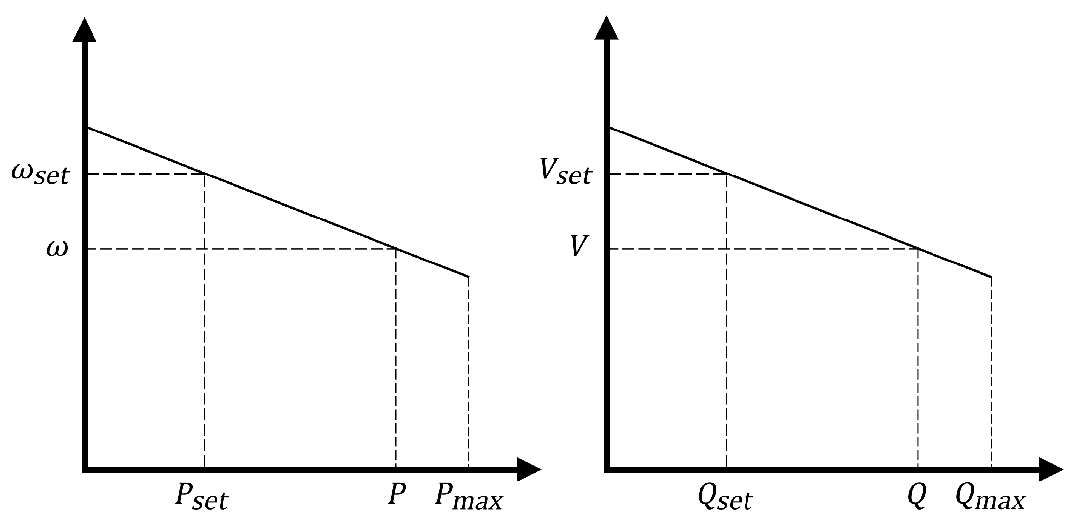
2.1. VSI Power and Droop Control

The primary control function for a VSI in an islanded MG network is implemented by the following conventional droop control laws as shown:
ω r e f = ω s e t k p ω 0 S r P = ω s e t m p P
V r e f = V s e t k q V 0 S r Q = V s e t n q Q
where V r e f and ω r e f are the reference voltage and frequency, respectively, and V s e t and ω s e t are the nominal setpoints for the voltage and frequency controllers, respectively. The rating of the VSI with respect to the base power S b a s e is given by S r = S i n v / S b a s e . The nominal frequency droop gain in per-unit at the maximum active power is k p , and the nominal voltage droop gain in per-unit at the maximum reactive power is k q . These nominal droop gains are often approximated to be within 0.5 3 % [18,25]. The nominal voltage and frequency are defined using V 0 and ω 0 , respectively. The active and reactive power outputs of the VSI are defined through the variables P and Q, respectively. The instantaneous active and reactive power values ( P i and Q i ) are filtered through a low pass filter with cutoff frequency ω c to remove oscillations and noise as shown:
P = ω c s + ω c P i , Q = ω c s + ω c Q i
By measuring the dq frame output current ( i o d , i o q ) and output voltage ( v o d , v o q ) signals, the instantaneous powers ( P i and Q i ) are obtained as shown:
P i = v o d i o d + v o q i o q , Q i = v o q i o d v o d i o q

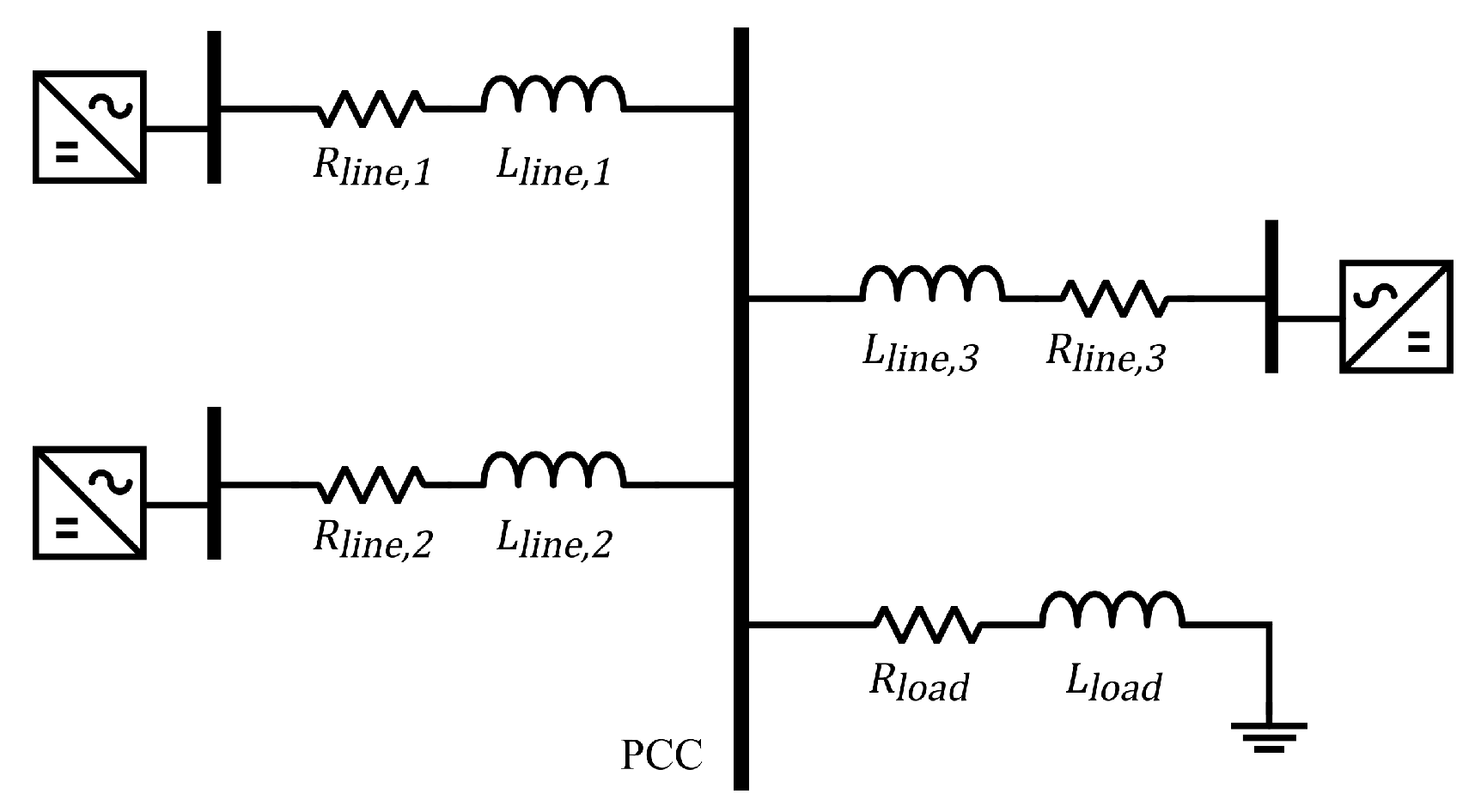
2.2. Interconnecting Load and Network

Consideration is made towards a generic R L load. The equations for the dq frame load currents connected at bus a is as shown:
d I l d , d , a d t = R l d , a L l d , a I l d , d , a + ω 0 I l d , q , a + V d , a L l d , a
d I l d , q , a d t = R l d , a L l d , a I l d , q , a ω 0 I l d , d , a + V q , a L l d , a
where the load inductance and load resistance are L l d , R l d , and the dq axis load currents are I l d , d , I l d , q , respectively. The dq axis bus voltages are V d , V q , respectively.
With consideration made towards a generic R L line, the equations for the dq frame line currents connected between adjacent buses a and b are as shown:
d I l n , d , a b d t = R l n , a b L l n , a b I l n , d , a b + ω 0 I l n , q , a b + V d , a V d , b L l n , a b
d I l n , q , a b d t = R l n , a b L l n , a b I l n , q , a b ω 0 I l n , d , a b + V q , a V q , b L l n , a b
where the line inductance and line resistance are L l n , R l n , and the dq axis line currents are I l n , d , I l n , q , respectively.
The full system model made up of Equations (1)–(8) for the VSI, the load and the network as extensively reported in the literature, is formulated in the dq frame [18,19,20,21,22,23,24,25].

2.3. Concept of the VSM

To mimic the inertia effect through the traditional second-order swing equation of synchronous machines for VSIs, the equation describing the active power droop control in Equation (1) and in conjunction with the filter equations (Equation (3)) can be rewritten as shown:
ω r e f = ω s e t m p ω c s + ω c P
The reference frequency can be assumed to follow the output frequency, i.e., ω r e f = ω , since the inner current and voltage loop act quick enough due to higher bandwidth [32]. In differential form, Equation (9) can be rewritten for a VSI at bus a, and reconstructed as shown:
d ω a d t = 1 τ a ( ω s e t , a ω a m p , a P a )
where the power controller’s filter time constant for the VSI at bus a is given by τ a = 1 / ω c , a . An analogy could then be made between Equation (10) and the traditional second-order swing equation [30,32,40]. The damping coefficient D and inertia J have the following relational proportionality:
D 1 m p ω 0 , J 1 m p ω c ω 0
From Equation (11), there is a functional equivalence between droop control and a VSM with a small inertia. The cutoff frequency, ω c , of the first order low pass filter serves an analogous function of the virtual inertia. Furthermore, an increasing droop gain, m p , implies a decreasing equivalence for the damping coefficient and therefore mathematically confirming that VSIs contribute more to damping of electromechanical modes [30,32,40]. From Equation (10), with the required level of accuracy, the angle at bus a where a VSI is connected can be described using:
d θ a d t = ω a ω 0
By mirroring Equation (10) and applying Equation (2) in conjunction with Equation (3), the reactive power and the voltage at bus a where a VSI is connected can be characterized using:
d V a d t = 1 τ a ( V s e t , a V a n q , a Q a )
To complete the mimicry of the VSI as a VSM, the algebraic equations shown below would also be included. The active and reactive power, identified by real ( ) and imaginary ( ) components generated by a VSI at bus a with lines and a load connected are:
P a = V a e j θ a b A a I l n , a b * + V a e j θ a I l d , a *
Q a = V a e j θ a b A a I l n , a b * + V a e j θ a I l d , a *
where A a is the set of bus numbers that are directly connected to bus a, and the following phasor equations shown below describe the voltage, load currents, and line currents respectively to be used in Equations (14) and (15):
V a = V d , a + j V q , a = V a e j θ a
I l d , a = I l d , d , a + j I l d , q , a
I l n , a b = I l n , d , a b + j I l n , q , a b

2.4. Concept of the PFT

Low-voltage MG networks are characterized as having non-negligible R / X line ratios compared to relatively negligible R / X line ratios that are common in medium- to high-voltage transmission networks where assumptions can be made stating P and ω are tightly coupled and also Q and | V | . This implies that P can be decoupled from | V | and Q decoupled from ω during control implementation. This assumption is unpractical in low-voltage MG networks as P and Q are both coupled to | V | and ω . Therefore, there is the need to modify the droop controls (1) and (2) using a PFT that takes into account the R / X ratio of the line impedance in order to account for and incorporate P | V | and Q ω coupling that is prevalent in low-voltage MG networks [36,37,38]. With the PFT, both P and Q have influences on both ω and | V | .
Using Figure 1, the conventional droop controls (1) and (2) can be rewritten for a VSI at bus a as shown:
ω a = ω s e t , a m p , a ( P a P s e t , a )
V a = V s e t , a n q , a ( Q a Q s e t , a )
where ω s e t and V s e t are the nominal setpoint frequency and magnitude of the output voltage at a non-zero setpoint active and reactive power, P s e t and Q s e t , respectively, when comparing Equations (1) and (2) with Equations (19) and (20). In other words, a non-zero P s e t and Q s e t in Equations (19) and (20) that corresponds to ω s e t and V s e t , respectively, both equal zero in Equations (1) and (2).
In a similar manner, Equations (10) and (13) can be rewritten for a VSI connected at bus a as shown:
d ω a d t = 1 τ a ω s e t , a ω a m p , a ( P a P s e t , a )
d V a d t = 1 τ a V s e t , a V a n q , a ( Q a Q s e t , a )
The PFT is shown in Equation (23) and a complete derivation appears in [36]. The resulting decoupled (or sometimes termed virtual) active and reactive powers indicated by P a and Q a for a VSI-fed bus a and a single line emanating from that bus are defined as shown:
P a Q a = X l n , a Z l n , a R l n , a Z l n , a R l n , a Z l n , a X l n , a Z l n , a P a Q a
where R l n , a , X l n , a and Z l n , a are the coupling line resistance, line inductive reactance, and line impedance magnitude from bus a, respectively. The conventional droop controls in Equations (19) and (20) would be modified and, subsequently, Equations (21) and (22) would incorporate the PFT at a bus a to a point of common coupling among the interconnected VSIs as follows:
ω a = ω s e t , a m p , a ( P a P s e t , a )
V a = V s e t , a n q , a ( Q a Q s e t , a )
d ω a d t = 1 τ a ω s e t , a ω a m p , a ( P a P s e t , a )
d V a d t = 1 τ a V s e t , a V a n q , a ( Q a Q s e t , a )
It should be noted that the modified droop controls via the PFT do not eliminate the cross-coupling between P and Q when the impedances offered by both R l n and L l n are comparable. However, it does seamlessly handle the transition to | V | controlling P and ω controlling Q that occurs in low-voltage MG networks as R l n increases relative to the impedance offered by L l n . For instance, in predominantly inductive lines, the PFT would ensure P P and Q Q ; whereas for predominantly resistive lines, the PFT acts differently and ensures P Q and Q P . It should also be noted that the PFT exhibits better load demand sharing in the parallel operation of VSIs operating in an islanded grid or connected to an infinite bus compared to VSIs operating in a meshed network. The functional purpose of the PFT is to transfer P and Q to a new reference frame where they are independent of the effective coupling line impedance.

3. Jacobian-Based Method

To control the VSIs within their maximum power capability, a Jacobian-based method is developed that aids in the VSI-MG to redistribute loads if one of the VSIs attains its output power capability. So, in the occurrence of an event, such as a change in load demand, a new steady-state network frequency can be established. The method proposed starts through the use of Equations (5)–(8), (12), (21) and (22) to characterize the dynamic states of the system should one choose to adopt the conventional droop controls (19) and (20) as was done in [35]. Alternatively, to implement the modified droop controls via the PFT as seen in Equations (24) and (25), Equations (5)–(8), (12), (26) and (27) are used to characterize the dynamic states of the system. Both scenarios are investigated within the paper. By applying appropriate numerical procedures, these dynamic states are computed as functions of time. While advancing the dynamic states in time, the algebraic active and reactive power Equations (14) and (15) are paid attention to for capacity violations. At the occurrence of a violation, Equation (28) describing correction terms is built at that time instant and used in amending the droop control laws.
Δ θ 1 Δ θ k Δ V 1 Δ V k = P 1 θ 1 P 1 θ k P 1 V 1 P 1 V k P k θ 1 P k θ k P k V 1 P k V k Q 1 θ 1 Q 1 θ k Q 1 V 1 Q 1 V k Q k θ 1 Q k θ k Q k V 1 Q k V k 1 P 1 r ( P 1 ^ P 1 ) P k r ( P k ^ P k ) Q 1 r ( Q 1 ^ Q 1 ) Q k r ( Q k ^ Q k )
In Equation (28), k is the last n-index in the subset k n and belongs to the set of all network buses N, where there is a connection to a VSI; and the invertible Jacobian matrix contains the partial derivatives of the active and reactive power equations (Equations (14) and (15)) with respect to angle and voltage dynamic states. For instance, in an MG network with 6 buses defined by the set N = { 1 , 2 , 3 , 4 , 5 , 6 } and having the subset k n = { 3 , 4 , 5 , 6 } where there is a connection to a VSI; the first and last entries ( 1 , 1 ) and ( k , k ) in the resulting 4– b y –4 Jacobian matrix would be P 3 / θ 3 and Q 6 / V 6 , respectively. The terms Δ θ a and Δ V a are the correction terms corresponding to a bus a in k n . The terms P a ^ and Q a ^ corresponding to a bus a in k n represent the operational active and reactive power capabilities of the VSI. P a ^ and Q a ^ are set to be less than the physical active and reactive power capabilities, P m a x and Q m a x of the VSI, respectively. This allows a margin in the application of Equation (28) as P a ^ and Q a ^ can be momentarily exceeded but not P m a x and Q m a x . The terms P a r and Q a r for a bus a in k n are ratio terms given by:
P a r = n k n P n P a , Q a r = n k n Q n Q a , a k n
In constructing Equation (28), on its rightmost column matrix, only the violation detected is entered with the other entries being made equal to zero. Then, the new correction terms on the leftmost column matrix of Equation (28) are computed and used to supplement the requisite dynamic states in Equations (12) and (22) if one chooses to adopt the conventional droop controls or supplement dynamic states in Equations (12) and (27) if one chooses to adopt the modified droop controls via the PFT, at the next iteration in time. This is shown in Equations (30)–(32). The correction terms Δ θ a and Δ V a approach zero when the violations are resolved.
d θ a Δ θ a d t = ω a ω 0
d V a Δ V a d t = 1 τ a V s e t , a V a n q , a ( Q a Q s e t , a )
With this amendable droop control, what occurs consequently is the collective slow retardation of the dynamic states that has a greater contribution continuously to the violation encountered. For a violation in active power, the angle states that contribute to that violation would incur a slightly increasing gradient to hold that violation while other VSIs increase their outputs to meet the active power generation insufficiency in the MG network. A similar occurrence is exhibited with a violation in reactive power and voltage states contributing to that violation. If adopting the modified droop controls via the PFT, both angle and voltage dynamic states experience the same phenomena because they both have contributing coupling effects to active and reactive power violations. By adopting this scheme, the VSIs would seek a new steady-state network frequency after the load demand has been redistributed from fully loaded VSIs to VSIs that have sufficient margin to meet a deficiency in power generation across the MG network. This is the load sharing scheme proposed.
A new steady-state network frequency can be reached if all VSIs in the MG network can cooperatively ride through and survive the power violation, and redistribute the load demand with adherence to the droop control method (conventional or PFT) adopted. Both droop control methods are “fixed gradient” methods and all interconnecting VSIs in the MG network seek this new point of operation in frequency on their respective gradients without exceeding its security margin set by its own power-generating capability. The Jacobian-based method developed would aid in this regard [35].

4. Simulation Studies and Results

The interconnected network shown in Figure 2 is a 381 V, 50 Hz VSI-MG under study. The parameters for this MG network including the VSI model parameters are presented in Table 1. The steady-state initial operating conditions in per-unit (on a 10 kVA, 381 V, 100 π rad/s base) were computed and are shown in Table 2. In Table 1 and Table 2, a corresponds to the associated bus and line number position in the order (1, 2, 3) of the VSI and is consistent with Figure 2. The operational power capability P a ^ and Q a ^ are set at 99 % of the physical power capability P m a x and Q m a x , respectively, for each VSI.

4.1. Simulation Results
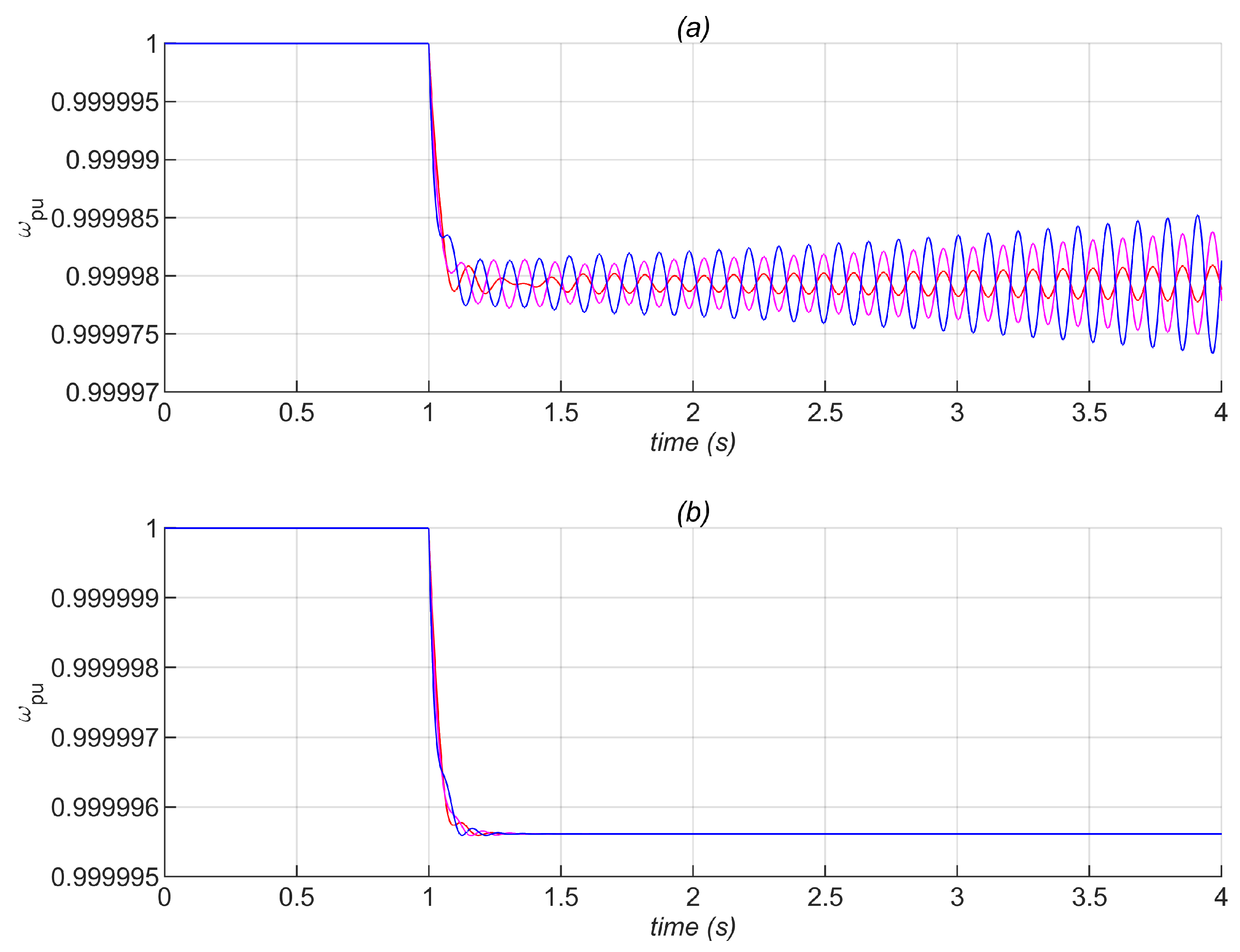
The initial load demand in per-unit at the point of common coupling (PCC) using the parameters in Table 1 is 1.5550 + j 0.3949 on a 10 kVA base. With the aid of MATLAB, and applying appropriate numerical methods incorporating the VSM and PFT concepts and in conjunction with the Jacobian-based method resulting in the amendable droop control, the following results are presented within.

4.1.1. Analyzing m p and Impact on Stability

The impact of increasing droop gain m p on stability in a VSI-MG network is extensively addressed in the literature. By increasing m p , the MG network becomes more oscillatory as some network modes move towards an unstable region and eventually leads to instability [5,18,19]. This is also consistent with the functional equivalence of the indirect relationship between m p and damping as mentioned when discussing the concept of the VSM [30,32,40]. As investigated in [18], the dominant eigenvalues correspond to low-frequency dominant modes and are also predominantly sensitive to the state variables of the power control scheme. These dominant eigenvalues are highly sensitive to m p . Comparisons are thus made between the conventional and PFT droop controls by increasing m p and presented in Figure 3 with regards to network frequency. At time = 1 s, the load demand is increased by 1 % and m p is increased from 0.2 % to 0.4 % . With the conventional droop control, the MG network becomes unstable at m p 0.38 % . Whereas with the PFT droop control, the MG network becomes unstable at m p 2.25 % . Figure 3 excludes the application of the Jacobian-based method. The PFT droop control thus expands the stability margin for the MG network.

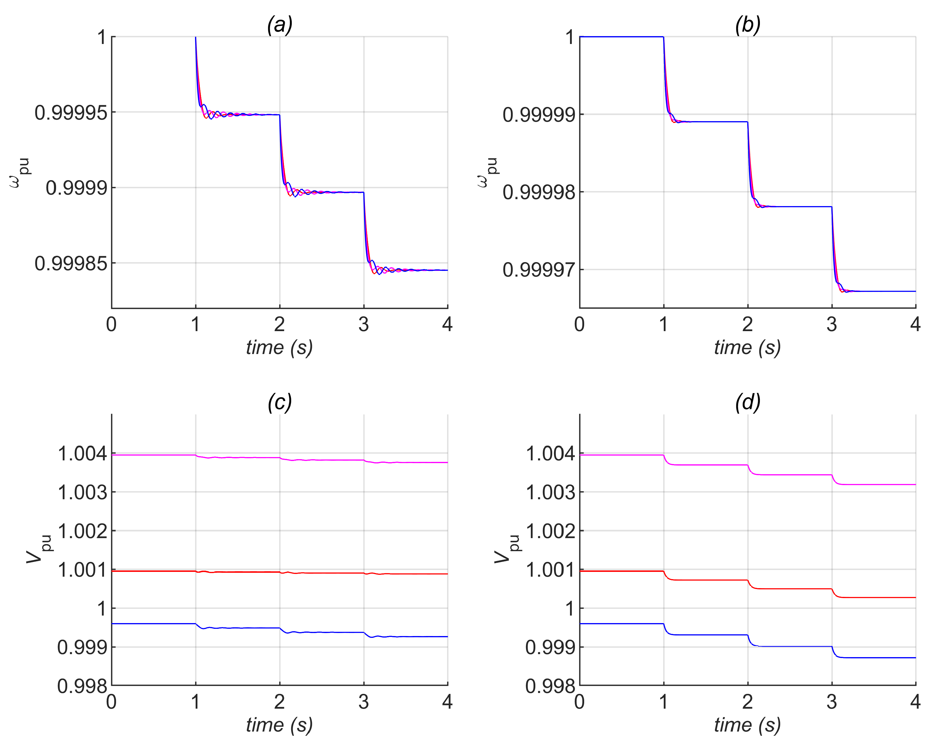
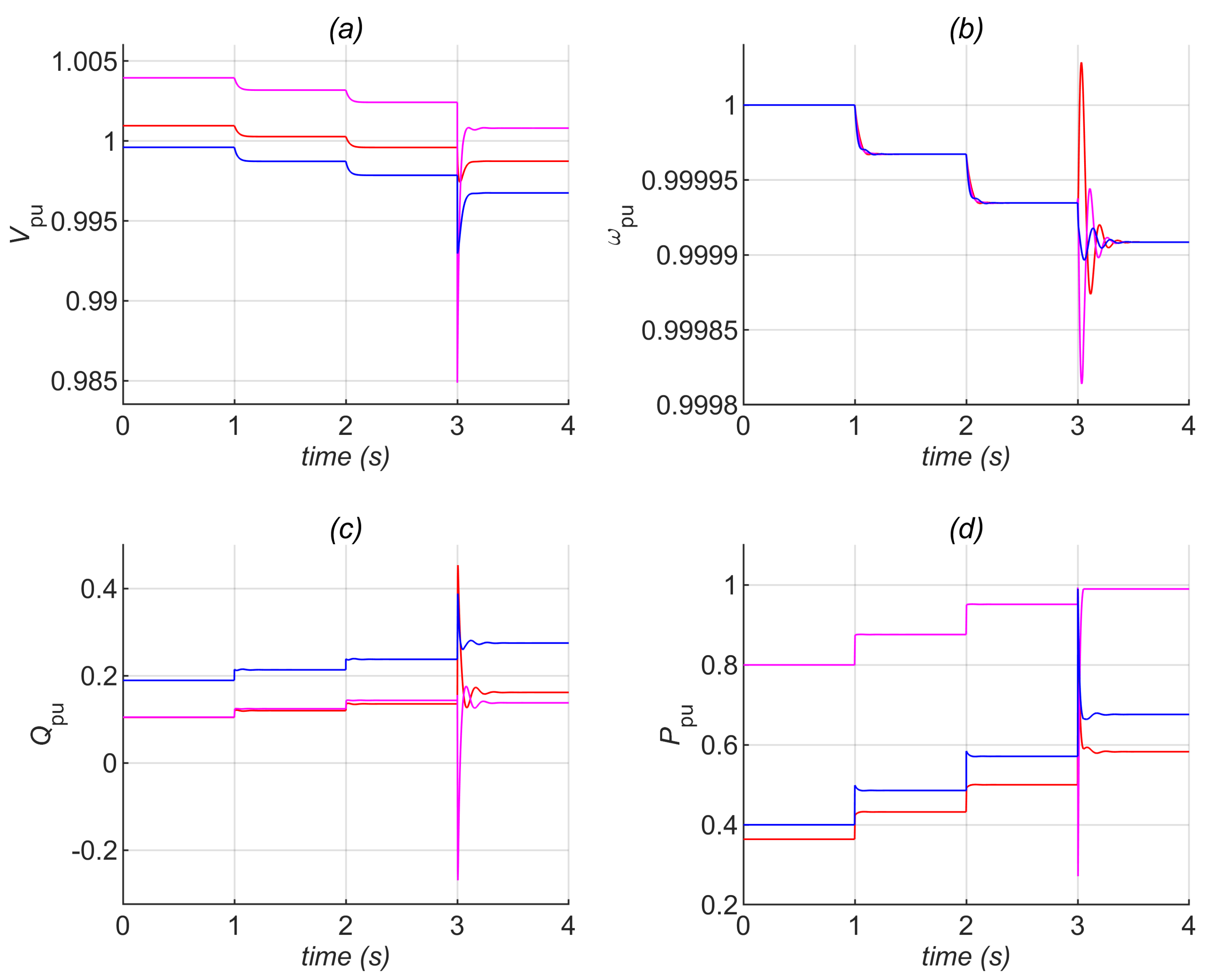
4.1.2. Voltage and Frequency Regulation

The transient response of bus voltages and network frequency are critical during power imbalances in the MG network. Comparisons are made between the conventional and PFT droop controls and presented in Figure 4. The load demand is increased by 5 % for each second in time. The results in Figure 4 exclude the application of the Jacobian-based method and shows the oscillatory behavior of the conventional droop control in comparison with the fairly non-oscillatory behavior of the PFT droop control. There is a more satisfactory transient voltage response and regulated frequency with the PFT droop control in comparison to the conventional droop control. Both voltage and frequency transient responses with the PFT droop control are a result of capturing the seamless transition to | V | controlling P and ω controlling Q that occurs in low-voltage MG networks as line resistances increases relative to line reactances. The R / X line ratio of the VSI-MG network in Figure 2 is ≈ 2.02 . For this reason, both ω and | V | have a controlling influence on P and Q as observed in the PFT droop control and are not decoupled as with the conventional droop control.

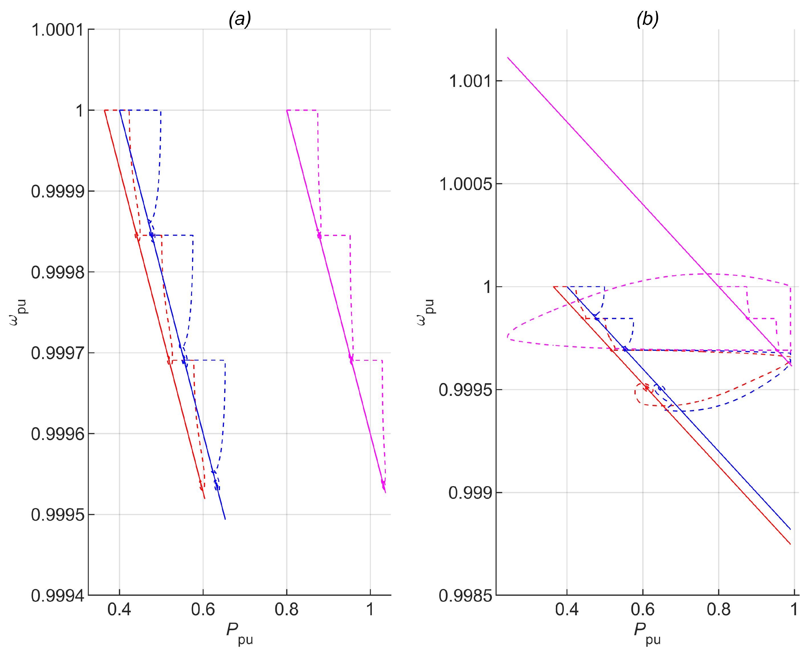
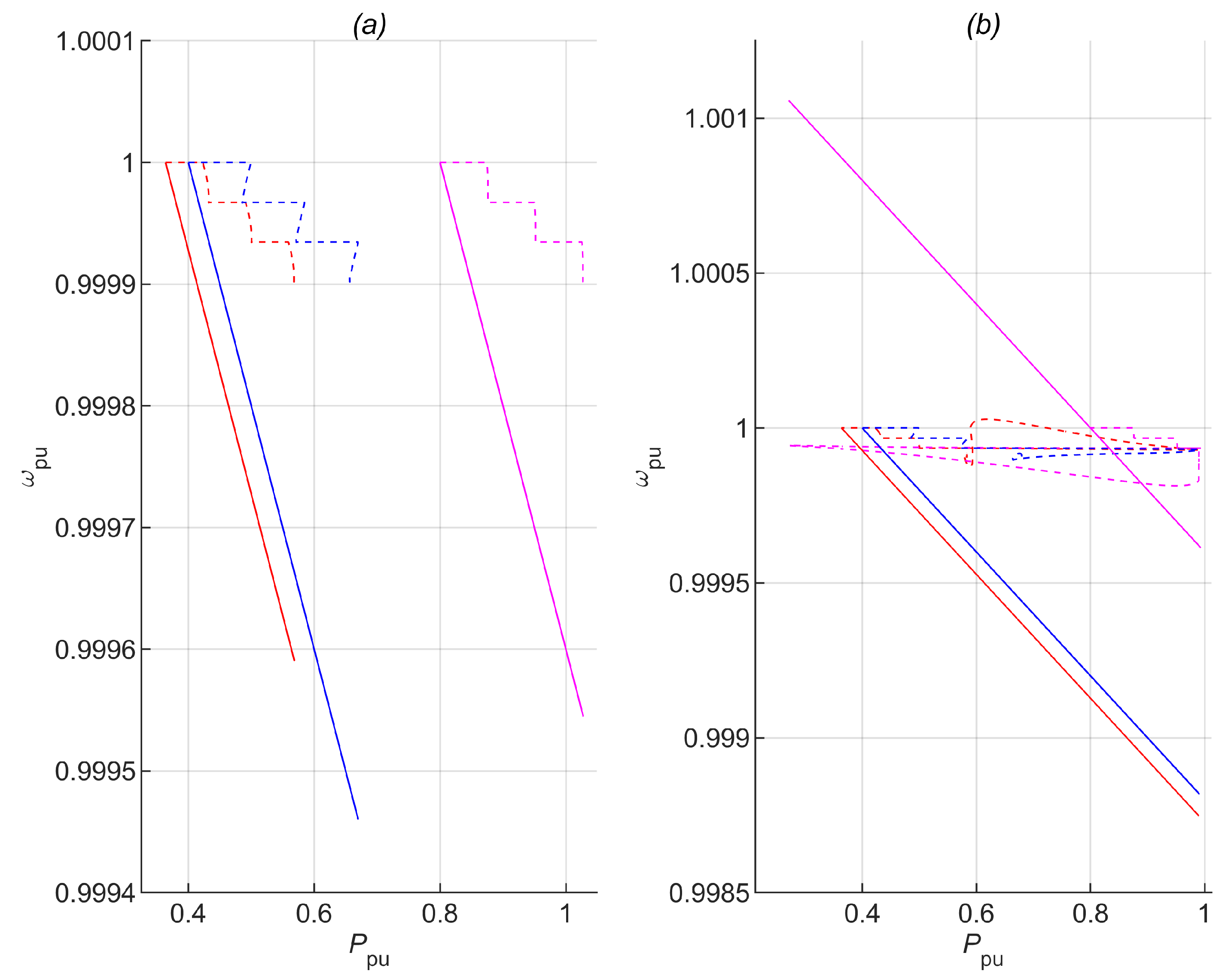
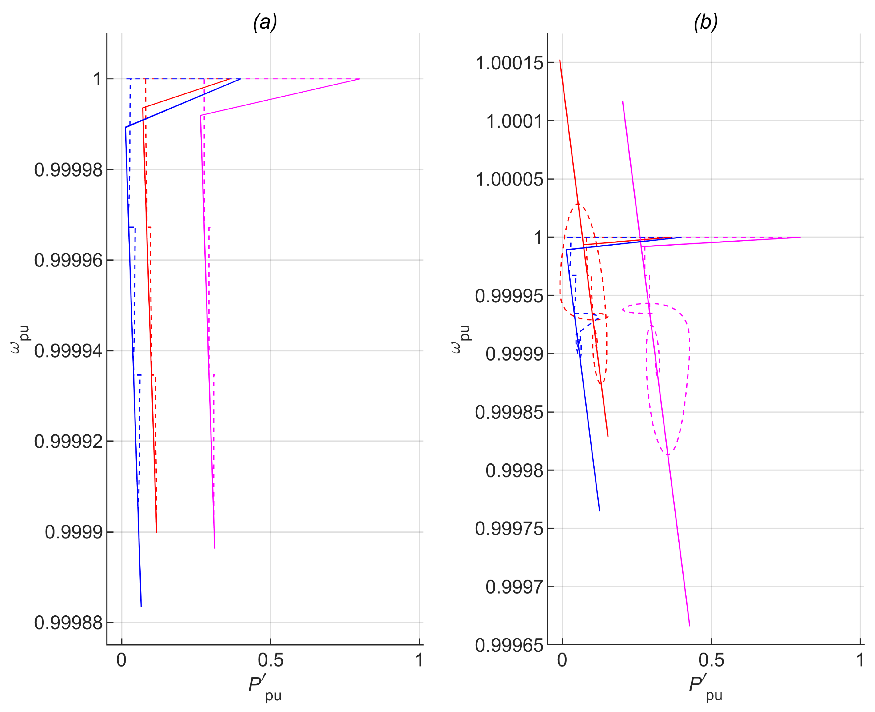
4.1.3. Application of the Jacobian-Based Method

With investigations into the impact m p has on stability and also the transient response of bus voltages and network frequency assessed, the Jacobian-based method is then incorporated with the PFT droop control. Its performance to changes in load demand in the presence of a fully loaded VSI is presented in Figure 5. The load demand is increased by 15 % for each second in time. The VSIs are all rated to supply an output active and reactive power of 1 p.u. With the application of the PFT droop control, the change in load demand is not shared equally among the VSIs and is not the focus of this paper. From Figure 5, the change in load demand is being shared with respect to both ω and | V | that have a controlling influence on P and Q. The active power output of the VSI at bus 2 momentarily reaches and exceeds its set operational power capability P a ^ of 0.99 p.u at time ≈3 s but not its physical power capability P m a x of 1 p.u. This triggers the amendment of Equations (12) and (27) resulting in Equations (30) and (32), respectively, for each VSI using Equation (28) in order to abate the increasing active power output from the VSI at bus 2, while the other VSIs ramp up their active power generation to meet any insufficiency. Accompanying this is a dip in voltage at bus 2 due to Equation (28) amending its voltage. Later at time ≈3.05 s, the VSI at bus 2 again reaches its operational power capability, but in this situation, the other VSIs slowly reach the sufficient active power generation required to sustain future occurrences of the VSI at bus 2 from exceeding its set operational power capability. The VSI-MG network is seen to attain a lower steady-state network frequency and bus voltages as the load demand increases.

4.2. Discussion

To illustrate the effectiveness of the Jacobian-based method in Equation (28), Figure 6, Figure 7 and Figure 8 show the search path (dashed lines) for equilibrium on the P ω conventional droop, the P ω PFT droop, and the P ω corrected PFT droop control characteristics, respectively. The load demand is increased by 15 % for each second in time. Although not drawn to scale, do note that Figure 6a,b and Figure 7a,b have the same droop gain, m p = 0.2 % . The droop gains are also the same in Figure 8a,b, but transformed through the PFT and hence termed “corrected”. The VSIs are all rated to supply an output active and reactive power of 1 p.u. While integrating the state equations over time, Equation (28) aids in averting each VSI from surpassing its set operational power capability.
In Figure 6, Figure 7 and Figure 8, the droop characteristics are represented by solid lines with a negative gradient. The response of the conventional droop controller, without and with Equation (28) are shown in Figure 6a,b, respectively. There is convergence on the P ω droop characteristics except in Figure 6b, where at a later time ≥3 s, Equation (28) supplements and amends Equations (12) and (22) resulting in Equations (30) and (31), respectively, to accommodate the active power output capability enforced by the VSI at bus 2. Similarly, the responses of the PFT droop controller, without and with Equation (28), are shown in Figure 7a,b, respectively. Convergence is not exhibited on the P ω droop characteristics, but Figure 7b shows Equation (28) still performing well by supplementing and amending Equations (12) and (27) which results in Equations (30) and (32), respectively, where at a later time ≥ 3 s, the active power output capability enforced by the VSI at bus 2 is still accommodated with fewer power violations compared to Figure 6b. Convergence is thus exhibited on the corrected transformed P ω droop characteristics, without and with Equation (28) as shown in Figure 8a,b, respectively.

5. Conclusions

In the presence of a fully loaded VSI, that is part of a VSI-MG, simulations were shown to validate the effectiveness of the Jacobian-based method proposed and the resulting amendable control. In the occurrence of an event, such as a change in load demand, loads are seen to be redistributed to VSIs with sufficient power generating margins to support the VSI-MG in the presence of a VSI attaining its maximum operational power capability. The conventional and PFT droop controls were compared with the latter shown to exhibit better transient responses and frequency regulation, reduce the number of power violations, expand stability margins and incorporate line characteristics to handle | V | and ω having a combined controlling impact on Q and P that occurs in low-voltage MG networks. Application and suitability to multi-bus MG networks having a number of buses without a direct connection to a VSI; and also scenarios investigating multiple power violations at the same time are open questions to be investigated. The Jacobian-based method described can be used to improve the ride-through capability of the VSI-MG network incorporating both the conventional and PFT droop controls. The intention is to facilitate efforts in maintaining system reliability and resiliency.

Author Contributions

Conceptualization, C.E. and Q.L.; methodology, C.E.; software, C.E.; validation, C.E. and Q.L.; writing—original draft preparation, C.E.; writing—review and editing, Q.L.; supervision, Q.L.; funding acquisition, Q.L. All authors have read and agreed to the published version of the manuscript.

Funding

This work is supported by the U.S. National Science Foundation under Grant ECCS-1808988.

Acknowledgments

The authors would like to gratefully acknowledge Guanyu Tian (University of Central Florida) and Petr Vorobev (Skolkovo Institute of Science and Technology) for insightful discussions and their suggestions towards this research.

Conflicts of Interest

The authors declare no conflict of interest.

References

  1. Lasseter, R.H. Microgrids. In Proceedings of the 2002 IEEE Power Engineering Society Winter Meeting, New York, NY, USA, 27–31 January 2002; pp. 305–308. [Google Scholar]
  2. Sen, S.; Kumar, V. Microgrid modelling: A comprehensive survey. Annu. Rev. Control 2018, 46, 216–250. [Google Scholar] [CrossRef]
  3. Arani, A.A.K.; Gharehpetian, G.B.; Abedi, M. Review on energy storage systems control methods in microgrids. Int. J. Electr. Power Energy Syst. 2019, 107, 745–757. [Google Scholar] [CrossRef]
  4. Eyisi, C.; Al-Sumaiti, A.S.; Turitsyn, K.; Li, Q. Mathematical models for optimization of grid-integrated energy storage systems: A review. In Proceedings of the 2019 North American Power Symposium (NAPS), Wichita, KS, USA, 13–15 October 2019; pp. 1–5. [Google Scholar]
  5. Parhizi, S.; Lotfi, H.; Khodaei, A.; Bahramirad, S. State of the art in research on microgrids: A review. IEEE Access 2015, 3, 890–925. [Google Scholar] [CrossRef]
  6. Sen, S.; Kumar, V. Microgrid control: A comprehensive survey. Annu. Rev. Control 2018, 45, 118–151. [Google Scholar] [CrossRef]
  7. Farrokhabadi, M.; Cañizares, C.A.; Simpson-Porco, J.W.; Nasr, E.; Fan, L.; Mendoza-Araya, P.A.; Tonkoski, R.; Tamrakar, U.; Hatziargyriou, N.; Lagos, D.; et al. Microgrid stability definitions, analysis, and examples. IEEE Trans. Power Syst. 2020, 35, 13–29. [Google Scholar] [CrossRef]
  8. Schiffer, J.; Zonetti, D.; Ortega, R.; Stanković, A.M.; Sezi, T.; Raisch, J. A survey on modeling of microgrids—From fundamental physics to phasors and voltage sources. Automatica 2016, 74, 135–150. [Google Scholar] [CrossRef] [Green Version]
  9. Sahoo, S.K.; Sinha, A.K.; Kishore, N.K. Control techniques in AC, DC, and hybrid AC–DC microgrid: A review. IEEE J. Emerg. Sel. Top. Power Electron. 2018, 6, 738–759. [Google Scholar] [CrossRef]
  10. Olivares, D.E.; Mehrizi-Sani, A.; Etemadi, A.H.; Cañizares, C.A.; Iravani, R.; Kazerani, M.; Hajimiragha, A.H.; Gomis-Bellmunt, O.; Saeedifard, M.; Palma-Behnke, R.; et al. Trends in microgrid control. IEEE Trans. Smart Grid 2014, 5, 1905–1919. [Google Scholar] [CrossRef]
  11. Han, H.; Hou, X.; Yang, J.; Wu, J.; Su, M.; Guerrero, J.M. Review of power sharing control strategies for islanding operation of AC microgrids. IEEE Trans. Smart Grid 2016, 7, 200–215. [Google Scholar] [CrossRef] [Green Version]
  12. Han, Y.; Li, H.; Shen, P.; Coelho, E.A.A.; Guerrero, J.M. Review of active and reactive power sharing strategies in hierarchical controlled microgrids. IEEE Trans. Power Electron. 2017, 32, 2427–2451. [Google Scholar] [CrossRef] [Green Version]
  13. Guerrero, J.M.; Chandorkar, M.; Lee, T.-L.; Loh, P.C. Advanced control architectures for intelligent microgrids—Part I: Decentralized and hierarchical control. IEEE Trans. Ind. Electron. 2013, 60, 1254–1262. [Google Scholar] [CrossRef] [Green Version]
  14. Eid, B.M.; Abd Rahim, N.; Selvaraj, J.; El Khateb, A.H. Control methods and objectives for electronically coupled distributed energy resources in microgrids: A review. IEEE Syst. J. 2016, 10, 446–458. [Google Scholar] [CrossRef]
  15. Ahn, S.-J.; Park, J.-W.; Chung, I.-Y.; Moon, S.-I.; Kang, S.-H.; Nam, S.-R. Power-sharing method of multiple distributed generators considering control modes and configurations of a microgrid. IEEE Trans. Power Deliv. 2010, 25, 2007–2016. [Google Scholar] [CrossRef]
  16. Chandorkar, M.C.; Divan, D.M.; Adapa, R. Control of parallel connected inverters in standalone AC supply systems. IEEE Trans. Ind. Appl. 1993, 29, 136–143. [Google Scholar] [CrossRef]
  17. Vijay, A.S.; Dheer, D.K.; Tiwari, A.; Doolla, S. Performance evaluation of homogeneous and heterogeneous droop-based systems in microgrid—Stability and transient response perspective. IEEE Trans. Energy Convers. 2019, 34, 36–46. [Google Scholar] [CrossRef]
  18. Pogaku, N.; Prodanovic, M.; Green, T.C. Modeling, analysis and testing of autonomous operation of an inverter-based microgrid. IEEE Trans. Power Electron. 2007, 22, 613–625. [Google Scholar] [CrossRef] [Green Version]
  19. Mohamed, Y.A.-R.I.; El-Saadany, E.F. Adaptive decentralized droop controller to preserve power sharing stability of paralleled inverters in distributed generation microgrids. IEEE Trans. Power Electron. 2008, 23, 2806–2816. [Google Scholar] [CrossRef]
  20. Bottrell, N.; Prodanovic, M.; Green, T.C. Dynamic stability of a microgrid with an active load. IEEE Trans. Power Electron. 2013, 28, 5107–5119. [Google Scholar] [CrossRef] [Green Version]
  21. Rasheduzzaman, M.; Mueller, J.A.; Kimball, J.W. An accurate small-signal model of inverter-dominated islanded microgrids using dq reference frame. IEEE J. Emerg. Sel. Top. Power Electron. 2014, 2, 1070–1080. [Google Scholar] [CrossRef]
  22. Luo, L.; Dhople, S.V. Spatiotemporal model reduction of inverter-based islanded microgrids. IEEE Trans. Energy Convers. 2014, 29, 823–832. [Google Scholar] [CrossRef] [Green Version]
  23. Nikolakakos, I.P.; Zeineldin, H.H.; El-Moursi, M.S.; Hatziargyriou, N.D. Stability evaluation of interconnected multi-inverter microgrids through critical clusters. IEEE Trans. Power Syst. 2016, 31, 3060–3072. [Google Scholar] [CrossRef]
  24. Rasheduzzaman, M.; Mueller, J.A.; Kimball, J.W. Reduced-order small-signal model of microgrid systems. IEEE Trans. Sustain. Energy 2015, 6, 1292–1305. [Google Scholar] [CrossRef]
  25. Vorobev, P.; Huang, P.-H.; Al Hosani, M.; Kirtley, J.L.; Turitsyn, K. High-fidelity model order reduction for microgrids stability assessment. IEEE Trans. Power Syst. 2018, 33, 874–887. [Google Scholar] [CrossRef] [Green Version]
  26. Piagi, P.; Lasseter, R.H. Autonomous control of microgrids. In Proceedings of the 2006 IEEE Power Engineering Society General Meeting, Montreal, QC, Canada, 18–22 June 2006; pp. 1–8. [Google Scholar]
  27. Kang, H.-K.; Ahn, S.-J.; Moon, S.-I. A new method to determine the droop of inverter-based DGs. In Proceedings of the 2009 IEEE Power & Energy Society General Meeting, Calgary, AB, Canada, 26–30 July 2009; pp. 1–6. [Google Scholar]
  28. Du, W.; Lasseter, R.H.; Khalsa, A.S. Survivability of autonomous microgrid during overload events. IEEE Trans. Smart Grid 2019, 10, 3515–3524. [Google Scholar] [CrossRef]
  29. Shuai, Z.; Sun, Y.; Shen, Z.J.; Tian, W.; Tu, C.; Li, Y.; Yin, X. Microgrid stability: Classification and a review. Renew. Sustain. Energy Rev. 2016, 58, 167–179. [Google Scholar] [CrossRef]
  30. D’Arco, S.; Suul, J.A. Virtual synchronous machines—Classification of implementations and analysis of equivalence to droop controllers for microgrids. In Proceedings of the 2013 IEEE Grenoble Conference, Grenoble, France, 16–20 June 2013; pp. 1–7. [Google Scholar]
  31. Beck, H.-P.; Hesse, R. Virtual synchronous machine. In Proceedings of the 2007 9th International Conference on Electrical Power Quality and Utilisation, Barcelona, Spain, 9–11 October 2007; pp. 1–6. [Google Scholar]
  32. Soni, N.; Doolla, S.; Chandorkar, M.C. Inertia design methods for islanded microgrids having static and rotating energy sources. IEEE Trans. Ind. Appl. 2016, 52, 5165–5174. [Google Scholar] [CrossRef]
  33. Liu, J.; Miura, Y.; Ise, T. Comparison of dynamic characteristics between virtual synchronous generator and droop control in inverter-based distributed generators. IEEE Trans. Power Electron. 2016, 3, 3600–3611. [Google Scholar] [CrossRef]
  34. Alsiraji, H.A.; El-Shatshat, R. Comprehensive assessment of virtual synchronous machine based voltage source converter controllers. IET Gener. Transm. Distrib. 2017, 11, 1762–1769. [Google Scholar] [CrossRef]
  35. Eyisi, C.; Tian, G.; Vorobev, P.; Li, Q. Load Sharing Strategy Incorporating Power Limits in Islanded Inverter-Based Microgrids. In Proceedings of the 2020 IEEE Electric Power and Energy Conference (EPEC), Edmonton, AB, Canada, 9–10 November 2020; pp. 1–6. [Google Scholar]
  36. De Brabandere, K.; Bolsens, B.; Van den Keybus, J.; Woyte, A.; Driesen, J.; Bemlans, R. A voltage and frequency droop control method for parallel inverters. IEEE Trans. Power Electron. 2007, 22, 1107–1115. [Google Scholar] [CrossRef]
  37. Qunais, T.; Karimi-Ghartemani, M. Systematic modeling of a class of microgrids and its application to impact analysis of cross-coupling droop terms. IEEE Trans. Energy Convers. 2019, 34, 1632–1643. [Google Scholar] [CrossRef]
  38. Raman, G.; Peng, J.C.-H. Mitigating stability issues due to line dynamics in droop-controlled multi-inverter systems. IEEE Trans. Power Syst. 2020, 35, 2082–2092. [Google Scholar] [CrossRef]
  39. Mohan, N. Electric Power Systems: A First Course; John Wiley & Sons: Hoboken, NJ, USA, 2012; pp. 178–188. [Google Scholar]
  40. Hou, X.; Sun, Y.; Zhang, X.; Lu, J.; Wang, P.; Guerrero, J.M. Improvement of frequency regulation in VSG-based AC microgrid via adaptive virtual inertia. IEEE Trans. Power Electron. 2020, 35, 1589–1602. [Google Scholar] [CrossRef]
Figure 1. Droop Control Characteristics.
Energies 14 05825 g001
Figure 2. VSI-MG Test Network.
Energies 14 05825 g002
Figure 3. Frequency (a) Conventional using m p = 0.4 % , (b) PFT using m p = 0.4 % ; at VSI Buses (1—red, 2—magenta, 3—blue).
Energies 14 05825 g003
Figure 4. (a) Frequency, Conventional, (b) Frequency, PFT, (c) Bus Voltages, Conventional, (d) Bus Voltages, PFT, at VSI Buses (1—red, 2—magenta, 3—blue).
Energies 14 05825 g004
Figure 5. (a) Bus Voltages, (b) Frequency, (c) Reactive Power Output, (d) Active Power Output, with Jacobian and PFT; at VSI Buses (1—red, 2—magenta, 3—blue).
Energies 14 05825 g005
Figure 6. P ω Droop Relation (a) no Jacobian, Conventional, (b) with Jacobian, Conventional; for VSIs at Buses (1—red, 2—magenta, 3—blue).
Energies 14 05825 g006
Figure 7. P ω Droop Relation (a) no Jacobian, PFT, (b) with Jacobian, PFT; for VSIs at Buses (1—red, 2—magenta, 3—blue).
Energies 14 05825 g007
Figure 8. P ω Droop Relation (a) no Jacobian, PFT corrected, (b) with Jacobian, PFT corrected; for VSIs at Buses (1—red, 2—magenta, 3—blue).
Energies 14 05825 g008
Table 1. Network and VSI Model Parameters.
ParameterDescription (Value)
S b a s e Inverter Base Apparent Power (10 kVA)
V 0 Nominal Voltage (381 V)
ω 0 Nominal Frequency ( 100 π rad/s)
ω c Filter Constant ( 10 π rad/s/W)
m p P ω Droop Gain ( 6.283 × 10 5 rad/s/W),
i.e., k p ( 0.2 % at P m a x = 10 kW)
n q Q V Droop Gain ( 3.81 × 10 4 V/Var),
i.e., k q ( 1 % at Q m a x = 10 kVar)
R l n Line Resistance ( 0.165   Ω /km)
L l n Line Inductance ( 0.26 mH/km)
l n a Line Length in km ( l n 1 = 1 , l n 2 = 0.8 , l n 3 = 0.6 )
R l d Load Resistance ( 8.7037   Ω )
L l d Load Inductance ( 7.0357 mH)
Table 2. Steady-State Initial Operating Conditions.
ParameterDescription (Value)
ω 0 Nominal System Frequency ( 1.0 )
V p c c Voltage at PCC ( 0.99623 )
θ p c c Voltage Angle in rad at PCC ( 0.00086 )
V a Bus a Voltages ( 1.00095 , 1.00395 , 0.99960 )
θ a Bus a Voltage Angles in rad ( 0.0 , 0.00178 , 0.00080 )
V s e t , a Nominal a-VSI Voltage Setpoints ( 1.0020 , 1.0050 , 1.0015 )
ω s e t , a Nominal a-VSI Frequency Setpoints
( 1.00073 , 1.00160 , 1.00080 )
P a + j Q a a-VSI Power Outputs ( 0.36383 + j 0.10459 ,
0.80000 + j 0.10511 , 0.40000 + j 0.18957 )
I l n , d q , a Line a Currents ( 0.36348 j 0.10449 ,
0.79704 j 0.10328 , 0.40001 j 0.18997 )
I l d , d q Load Current ( 1.56053 j 0.39773 )
Publisher’s Note: MDPI stays neutral with regard to jurisdictional claims in published maps and institutional affiliations.

