Article

Synthesis and Analysis of Three-Port DC/DC Converters with Two Bidirectional Ports Based on Power Flow Graph Technique

1
Faculty of Engineering and Information Technology, University of Technology Sydney, Sydney, NSW 2007, Australia
2
Department of Electrical Engineering, City University of Hong Kong, Tai Chee Avenue, Kowloon Tong, Hong Kong
3
Institute for Superconducting and Electronic Materials, AIIM, University of Wollongong, Wollongong, NSW 2522, Australia
*
Author to whom correspondence should be addressed.
Energies 2021, 14(18), 5751; https://doi.org/10.3390/en14185751
Submission received: 10 July 2021 / Revised: 5 September 2021 / Accepted: 10 September 2021 / Published: 13 September 2021

Abstract

:
This paper presents a systematic topological study to derive all possible basic and non-isolated three-port converters (TPCs) using power flow diagrams. Unlike most reported TPCs with one bidirectional port, this paper considers up to two bidirectional ports and provides a comprehensive analytical tool. This tool acts as a framework for all power flow combinations, selection, and design. Some viable converter configurations have been identified and selected for further analysis.

1. Introduction

Power electronic converter is an interface which allows the integration of different energy sources to perform efficient power conversion, fast control, and effective power conditioning [1,2,3,4,5]. Using multiple separate single-input single-output (SISO) converters may produce an inefficient, costly, and bulky design [6]. Therefore, multiple-port power converters have been presented to cover the requirements of different applications, such as photovoltaic battery hybrid system [7] and fuel-cell supercapacitor hybrid power system [8]. Renewable energy sources (RESs), such as solar energy, become an important complement or even replacements of conventional energy sources due to their sustainable supply of energy for long term. To get continuous and more stable power from RESs, there is a need to integrate the energy storage elements, such as batteries, supercapacitors, and flywheeels, etc. This will not only provide stable power supply for the loads but also improve the overall system reliability.
Consequently, different topologies of possible three-port converters should be available to cater for various types of input sources and load ports [9,10,11,12]. These ports could be a unidirectional port, such as a PV energy source, or a bidirectional port, such as battery or DC bus [13,14]. Therefore, the arrangement of converters and controlling the power flow distribution of the TPCs plays a vital role on the overall performance and efficiency. Nevertheless, a number of research studies have been presented for TPCs along with different topologies. However, to the best knowledge of the authors, few papers have provided a systematic topological study and a comprehensive comparison among these different configurations [6]. In [15], a systematic analytical technique for different configurations is constructed. The extension of this work with different buck, boost, and buck-boost converters is presented [16,17]. In [18], a comprehensive topological study and comparison of five different structures of three-port DC/DC converters are presented. However, some TPCs cannot be derived based on these five structures as in [19,20], where some ports share components. Furthermore, these five structures provide a general structure but does not show exactly how the power flow through these ports is and if it is fully or partially controlled. However, for some applications, such as electric vehicles, a bidirectional output port is needed to handle regenerative braking [21,22]. Therefore, in paper [23], all possible power flow combinations had been studied for two bidirectional ports. This paper extends the work in [23] through a systematic topological study of all power flow combinations with particular focus on practical design and implementation of a selected topology for a practical application.
This paper focuses on providing a systematic topological study to derive all possible configurations of TPC with two bidirectional ports in contrast to [15] where the output port was unidirectional. The significance of this work is to investigate and demonstrate which configuration has less power conversion stages between any two ports. Furthermore, it shows if all ports are fully or partially controlled, as well as presenting the appropriate configuration for specific applications. The paper is organised as follows: in Section 2, a brief review of a systematic topological derivation of three-port converters with one bidirectional port. In Section 3, a brief review of power flow graphs is discussed. Followed by the power flow graph derivation for two bidirectional ports is proposed. In Section 4, circuit realisation based on proposed power flow graphs are proposed. In Section 5, principles of operation of Type I-III-IC is explained briefly, followed by conclusion in Section 7.

2. A Review of Three-Port Configurations

There are many ways of deriving the TPCs’ configuration, as explained previously in [15,16,17,18,24]. In [15], a systematic analytical technique for different configurations is constructed based on the power flow graph tool. The extension of this work with different buck, boost, and buck-boost converters is presented in [16]. This work was specifically designed for some specific configurations. Similarly, power flow graphs have been used to construct different configurations for IoT applications, as in [17]. A computer program was used to drive different topologies of three-port converters [25]. As compared to the manual derivation method, this programmable method is faster and covers more viable topologies. However, the main structure is limited to one inductor and three switches. Therefore, any changes in the three-port converter, such as the bidirectional port, leads to a repeat of the whole derivation process. In [18], five TPC structures were constructed limited to a single bidirectional port. Therefore, this paper focuses on analyzing two bidirectional ports where all these structures are modified, as shown in Figure 1. These structures are evaluated comprehensively based on three dimensions: efficiency, the complexity of the topology, and control simplicity. A comparison of these five structures is outlined in Table 1.
Many factors can affect the efficiency of a TPC. One factor is the number of power processing stages between any two ports. The TPC structure in Figure 1a is the best in terms of efficiency as a single power processing between any two ports. The TPC structures in Figure 1c,d come after the TPC structure in Figure 1a as two paths have single power processing. After that, the TPC structure in Figure 1b has two paths of single power processing. However, it has two power processing in the primary path (PV source to DC bus). Finally, the TPC structure in Figure 1e has two power processing between any two ports. Based on the topology complexity, the TPC structures in Figure 1b,c are the best, as only two converters are needed. The next best is the TPC structure in Figure 1d, where two converters are bidirectional, then the TPC structure in Figure 1a, which has two unidirectional converters and one bidirectional converter. Finally, the TPC structure in Figure 1e has two bidirectional converters and one unidirectional converter. This feature could be advantageous based on the control simplicity as fewer control parameters (controller) are used. However, the system will have less control objective as well. Therefore, the TPC structures in Figure 1b,d are the simplest as every converter achieves one control objective for all different modes of operation. The TPC structure in Figure 1c has two control objectives. However, these objectives will change in different modes, which increase the complexity of this structure. Finally, the TPC structure in Figure 1a,e has three control objectives which are the most complex to control.

3. Power Flow of Three-Port Converters

Power flow graphs technique was first presented in [26,27] for power factor correction PFC converters. The technique is extended in [15] to derive all possible three-port DC/DC converters with unidirectional output power. Similar technique is used here to drive all possible TPCs with two bidirectional ports.

3.1. Power Flow Subgraphs

There are three types of power flow subgraphs: (1) In Type I, the power is transferred separately from one port to another, as shown in Figure 2a; (2) Type II, the power is transferred simultaneously from two ports to one, as shown in Figure 2b; (3) In Type III, the power is transferred simultaneously from one port to two ports, as shown in Figure 2c. If all ports are unidirectional, only Type I and Type II are used.

3.2. Power Flow Graphs for One Bidirectional Port

Power flow graph configuration consists of a mixture of power flow subgraphs that ensure all ports are connected together and describe the paths of power transfer. Based on that, all possible combinations are studied, such as two of Type I, two of Type II, two of Type III, Type I + Type II, Type I + Type III, and so on. After the derivation, all impractical configurations are eliminated. One example of input ports being bidirectional (for battery application, for example) and one unidirectional output port had been studied in [15]. Based on the power flow subgraphs, as shown in Figure 2, complete power flow graphs for all double-input single-output (DISO) converters are constructed in Figure 3. All possible converter connections are explained in four different power flow graphs, namely, Type I-I, Type I-II, Type I-III, and Type II-III. Type I-I graph which integrates two of Type I subgraphs and so on. Type II-II and Type III-III are not acceptable because Type II-II makes output port bidirectional which is unnecessary and Type III-III makes a redundant power flow graph.

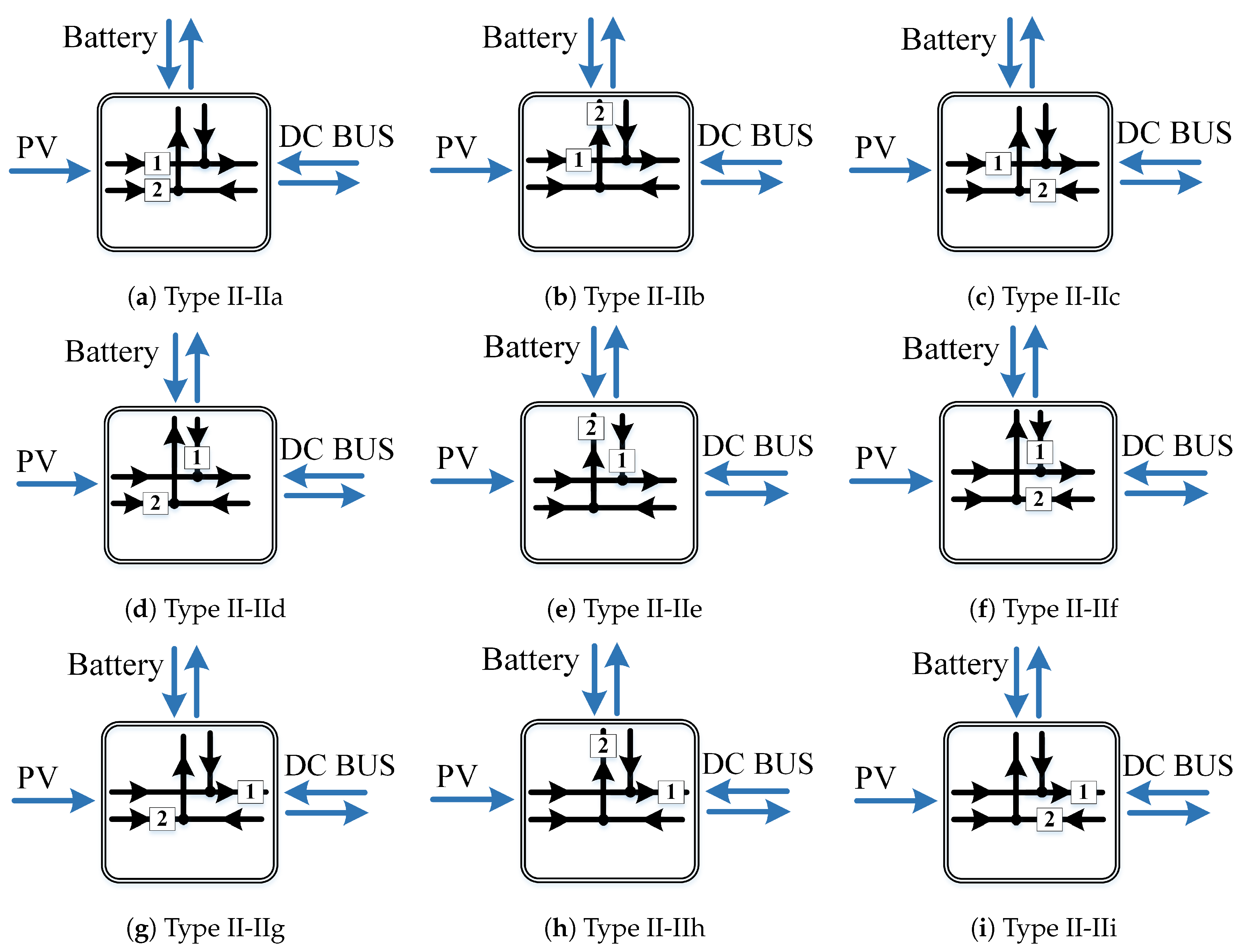
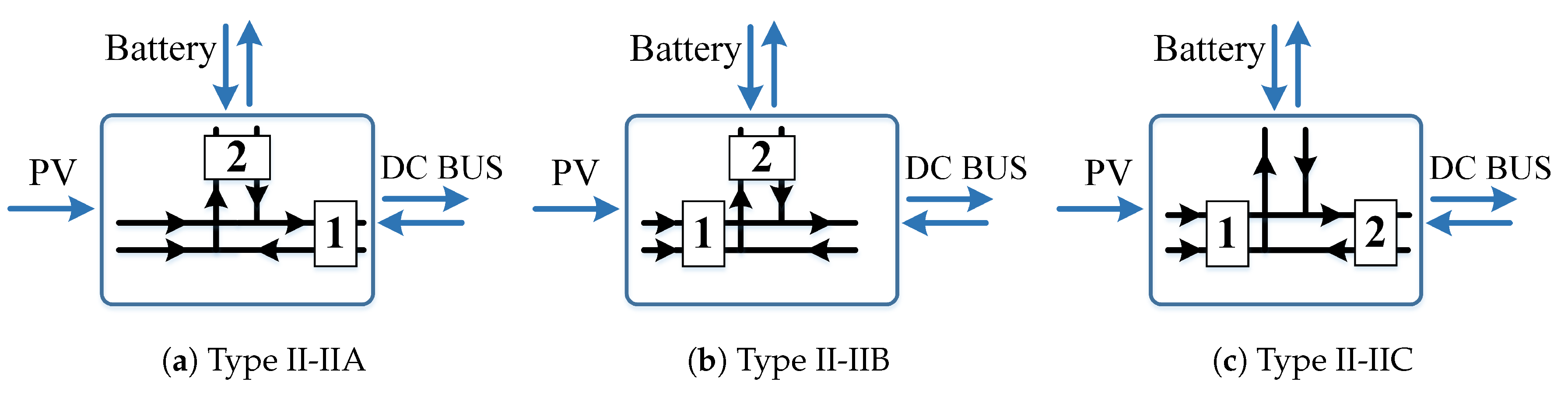
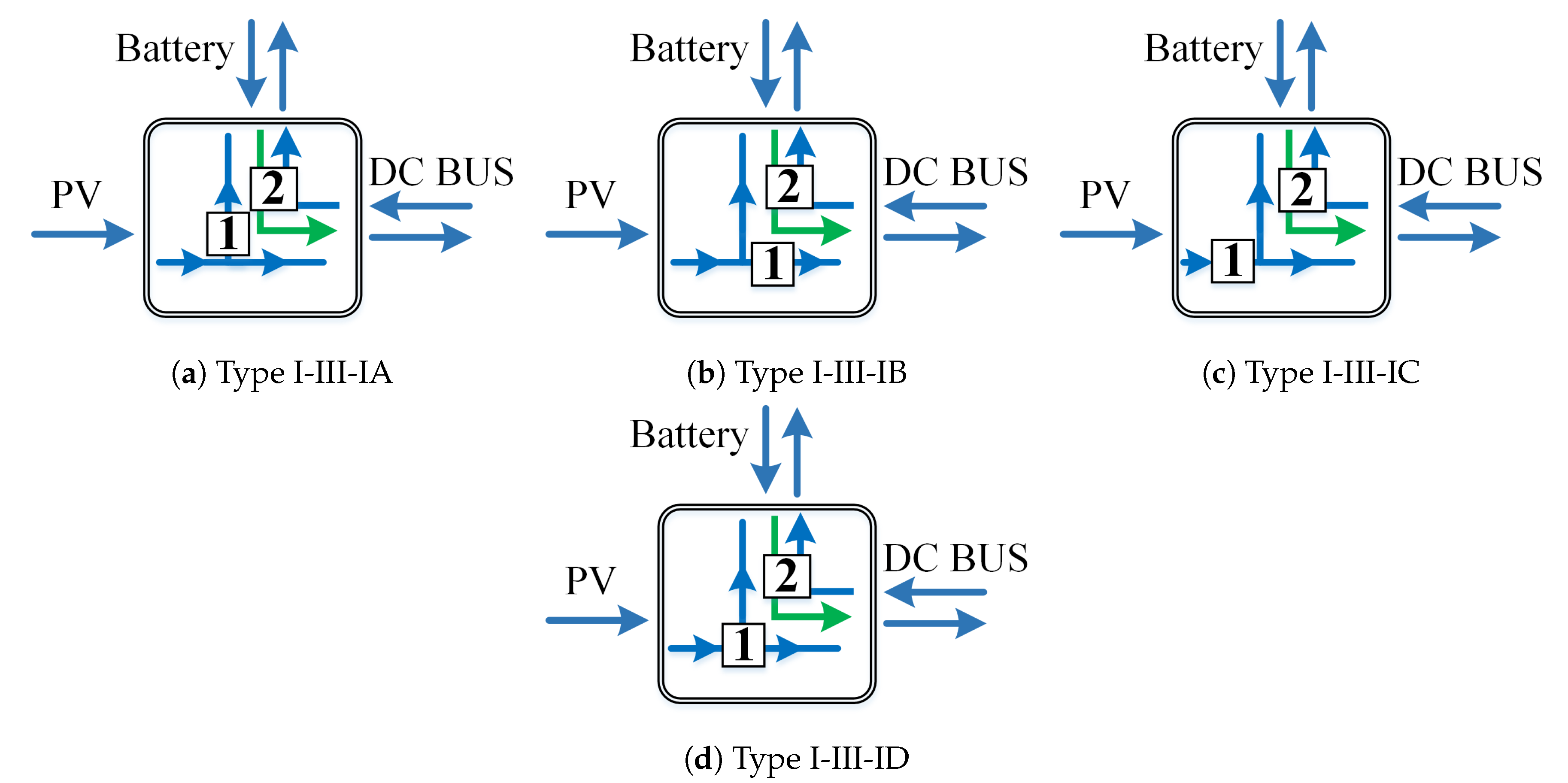
3.3. Proposed Power Flow Graphs Derivation for Two Bidirectional Port

In addition to the battery, a bidirectional output port is useful in applications, such as electric vehicles (regenerative/braking mode) and DC microgrids. Power flow subgraphs of three-port converter with a bidirectional output port are the same as the unidirectional output port as in Figure 2. In this paper, PV is considered one of the renewable energy sources for the input port, and a DC bus is the bidirectional output port.
All possible combinations of power flow subgraphs are studied to ensure that all ports are connected together with minimum power flow paths. Starting from Type I, a minimum of three of Type I is required to connect all ports. Therefore, two power flow graphs illustrating three Type-I configurations are shown in Figure 4a, and Figure 4b using all ports. However, one power flow path is not considered, such as in Type I-I-IA, PV to the battery or in Type I-I-IB, PV to the DC bus. Therefore, four of Type I is constructed in Figure 4c. Additionally, these configurations are separated and require three individual converters, which results in less efficient and costly system. As a result, power flow graphs of Type I and Type II are mixed, the resultant configurations are shown in Figure 4d, and Figure 4e. However, no direct connection between PV to battery as shown in Figure 4d, and no direct connection between PV to DC bus, as shown in Figure 4e exists. To overcome this issue, Type I-II-IA and Type I-II-IB are presented, as in Figure 4f and Figure 4g, respectively. However, the last two configurations increase the number of switches. Another possible combination is one power flow graph of two of Type II, as shown in Figure 4h. The last possible combination is two of Type I with Type III, as shown in Figure 4i. The advantage of this configuration is in using the Type III configuration, which has one input (PV) and two outputs (battery and DC bus), with a bidirectional converter connected between the battery and DC bus. It is worth noting that there are no possible configurations of Type II-III and Type III-III as one direction of the bidirectional port will not be connected in this power flow configuration. As clearly displayed in Figure 4, there are significant changes in the power flow graphs in comparison to a one bidirectional port in [15] and is presented in Figure 3.
According to the circuit theory [26], to construct two subgraphs together, a minimum of two separate and basic converters are required. Therefore, two converters are placed on the power flow graphs in proper paths to build all possible three-port converters, as in Figure 5. In Figure 5a, one unidirectional converter connects the PV to DC bus, and a bidirectional converter is connected between the battery and the DC bus. The difference between Figure 5a,b is the connection of the PV source with the battery instead of the DC bus. In Figure 5c, two unidirectional converters and one bidirectional converter have been used. Figure 5d,e have a central converter with a bidirectional port from the DC bus and the battery. The only difference is the connection of the unidirectional converter.
For Type II-II, two converters are placed on the power flow graphs in their proper paths to build all possible three-port converters using only unidirectional SISO converters, as in Figure 6. Upon further inspection of each configuration, one of the ports is connected directly without a converter, leaving it out of control. Therefore, there is a trade-off between controllability and the number of converters. As the direction of this work is towards full control, only three configurations, where all ports are controlled, are useful, as in Figure 7. It is worth noting that Type II-IIA and Type II-IIB are equivalent to P1S3-I and P1S3-II structures, respectively. In addition, an example of each of these configurations are presented in [23,28].
Similarly, Type I-III-I configurations are proposed in Figure 8. All of these configurations have a bidirectional converter between the battery and the DC bus. In Figure 8a, the PV source is connected directly to the DC bus and to the battery through a unidirectional converter. In Figure 8b, the PV is connected directly to the battery. In Figure 8c, the PV source is connected to the DC bus and the battery through a converter. In Figure 8d, the PV source is connected to the battery and DC bus through a central converter. In Figure 5, Figure 6, Figure 7 and Figure 8, converters 1 and 2 could be transformer-based, bridge-based, Ćuk, ZETA, SEPIC, or basic converters, such as buck, boost, or buck-boost converters. Therefore, for simplicity, only basic converters will be considered, as shown in Table 2. Type I-III-IA and Type I-III-IB are identical due to spatial symmetry between the two bidirectional ports. Therefore, both of them have the same combinations. This paper studies all possible power flow graphs more specifically those converters having three power flow sub graphs. Each of these configurations has been studied, and and circuit realisation undertaken.

4. Circuit Realisation Based on Proposed Power Flow Graphs

This section includes the circuit realisation based on the proposed power flow graphs, which was initially proposed in the previous section. A Type I-II-IA circuit is based on the power flow graph shown in Figure 9. This structure has a central converter and a unidirectional converter between the PV source to the battery. The central converter can achieve the PV source to the battery and the DC bus through a single inductor by using two paths. These two sources have the time-sharing between them to ensure the switches are working in an alternate pattern [29,30]. In addition, a bidirectional path can be constructed between the DC bus and battery using the same central converter. Finally, a separate converter is used to connect the PV source to the battery. Compared with other topologies, this topology can achieve single power processing for all seven modes at the cost of adding only one additional switch.
The first circuit of Type I-III-IA, in Figure 10a is based on the proposed power flow graph as depicted in Figure 8a. This configuration has a direct connection between the PV source and the DC bus. The first converter is connected between the PV source and the battery. The second converter is a bidirectional converter between the battery and the DC bus. This converter will have high efficiency in the PV source to the battery and the DC bus mode as it involves single power processing among the ports. Similarly, the battery to the DC bus and the DC bus to the battery mode also involves single power processing. On the other hand, to achieve the PV source to the DC bus and the PV source to the battery modes, all switches are required to complete the path and achieve these modes. This results in double power processing, which will degrade the efficiency but ensure that the system will work even if the battery or the DC bus are disconnected.
The second circuit of Type I-III-IB, in Figure 10b is based on proposed the power flow graph as depicted in Figure 8b. This configuration has a direct connection between the PV source and the battery. The first converter is connected between the PV source and the DC bus. The second converter is a bidirectional converter between the battery and the DC bus. This converter will have high efficiency in the PV source to the battery and the DC bus mode as it involves single power processing among the ports. Similarly, the battery to the DC bus and the DC bus to the battery mode involves single power processing. On the other hand, in order to achieve the PV source to the DC bus and the PV source to the battery modes, all switches are required to complete the path and achieve these modes. As above, this results in double power processing, which will degrade the efficiency but will ensure that the system will work even if the battery or the DC bus are disconnected.
The third circuit of Type I-III-IC configuration is realised based on the proposed power flow graph in Figure 10c. This configuration has a direct connection between the battery and the DC bus. The first converter is connected between the PV source to the battery and the DC bus. The second converter is a bidirectional converter between the battery and the DC bus. This converter can have high efficiency in the PV source to the battery and the DC bus mode as it involves single power processing among the ports. Similarly, the battery to the DC bus and the DC bus to the battery mode also involves single power processing. This converter works similar to the converter mentioned above in the PV source to the DC bus and the PV source to the battery modes.
The fourth circuit of Type I-III-ID is based on the power flow graph shown in Figure 10d. This structure has a central converter and a bidirectional converter between the battery and the DC bus. The central converter can couple the PV source to the battery and the DC bus through a single inductor using a different path but increases the number of switches.
However, the PV source to the DC bus and the PV source to the battery mode is achievable through single power processing without using all the switches to complete the path.

5. Principles of Type I-III-IC Operation

This section discusses principles of operations and simulation results of Type I-III-IC, which has been chosen for the purpose of illustration. The converter connected with the PV source to the battery and the DC bus is a boost converter. The battery is connected to the DC bus using a bidirectional buck-boost converter. The circuit realisation is shown in Figure 10c. These simulations results include Mode 5, 6, and 7, as the first four modes are SISO which are easy to implement. According to design requirement, the converter operates in continuous conduction mode (CCM) [32]. The circuit has seven modes of operation. These modes are discussed as below:
1.
PV to DC bus: In this mode, the PV source supplies the power only to the DC bus as the battery is at maximum SoC;
2.
PV to battery: In this mode, the PV source supplies the power to the battery at no load condition;
3.
Battery to DC bus: In this mode, the battery supplies the power to the DC bus as the PV source cannot supply power during nighttime;
4.
DC bus to Battery: In this mode, the DC bus supplies the power to the battery as the PV source cannot supply power during nighttime;
5.
PV to battery and DC bus: In this mode, the PV source has sufficient power to supply the battery and the DC bus. Figure 11 shows two switching states and explained as follows:
  • State I [ t 0 < t < t 1 ]: S 1 is turned ON. The PV source starts to charge the inductor where I L 1 = I P V , as shown in Figure 11a. When S 1 turns OFF at t = t 1 , this state ends;
  • State II [ t 1 < t < t 2 ]: S 1 is turned OFF. L 1 starts to discharge to the battery and the DC bus, as shown in Figure 11b. When S 1 turns ON at t = t 2 , this state ends. The simulation waveforms are shown in Figure 11c.
6.
PV and battery to DC bus: In this mode, the battery and the PV source provide the power to the DC bus. The system now operates as a DISO converter. Figure 12 shows four switching states and explained as follows:
  • State I [ t 0 < t < t 1 ]: S 1 and S 3 are turned ON while S 2 , S 4 are OFF. PV starts to charge L 1 . In addition, L 2 starts to charge from the battery via S 3 , as shown in Figure 12a. The voltage across L 1 is given by v L 1 = V P V and that across the inductor L 2 is given by v L 2 = V B . This mode ends when S 3 turns OFF at t = t 1 ;
  • State II [ t 1 < t < t 2 ]: S 1 and S 4 are turned ON while S 2 , S 3 are OFF, PV source continues to charge L 1 . In addition, L 2 starts to discharge into the DC bus and C 2 , as shown in Figure 12b. The voltage across L 1 is given by v L 1 = V P V and across L 2 is given by v L 2 = V D C . This mode ends when S 1 turns OFF at t = t 2 .
  • State III [ t 2 < t < t 3 ]: S 2 and S 4 are turned ON while S 1 , S 3 are OFF, L 1 starts to discharge to the battery via S 2 . In addition, L 2 continues to discharge into the DC bus and the capacitor C 2 , as shown in Figure 12c. The voltage across the inductor L 1 is given by v L 1 = V P V V D C V B and across L 2 is given by v L 2 = V D C . This mode ends when S 3 turns ON at t = t 3 ;
  • State IV [ t 3 < t < t 4 ]: S 2 and S 3 are turned ON while S 1 , S 4 are OFF. L 1 continues to discharge into the battery. In addition, L 2 start to charge from the battery and C 1 , as shown in Figure 12d. The voltage across L 1 is given by v L 1 = V P V V D C V B and across L 2 is given by v L 2 = V B . This mode ends when S 1 turns ON at t = t 4 . The simulation waveforms are shown in Figure 12e;
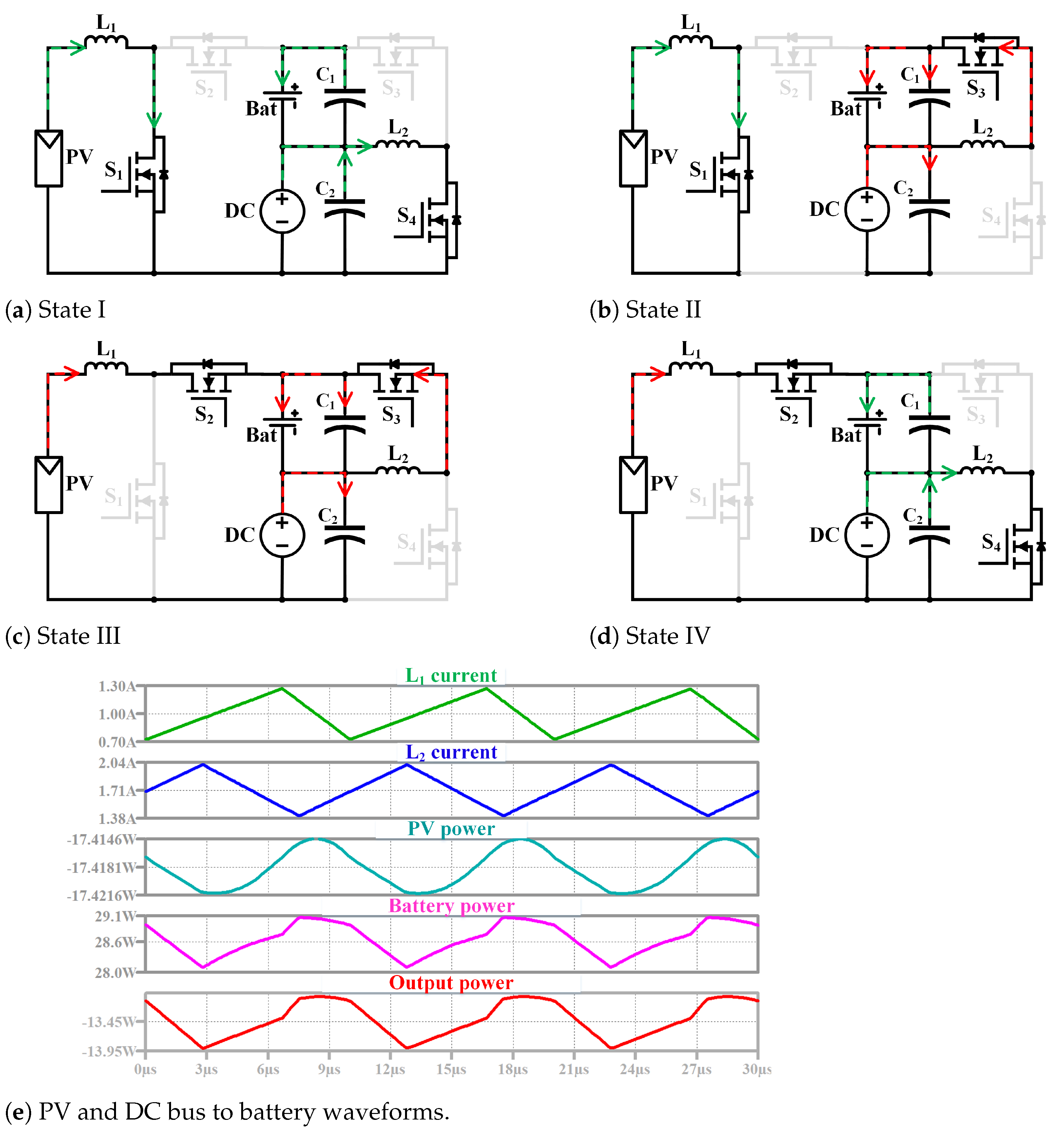
7.
PV and DC bus to battery: As the battery is low in SoC, as well as PV source is generating less power, therefore DC bus and PV source together charge the battery at the rated current. The TPC operates as a DISO converter. This mode consists of four switching states, as shown in Figure 13 and as follows:
  • State I [ t 0 < t < t 1 ]: S 1 and S 4 are turned ON while S 2 and S 3 are OFF. The PV source starts to charge L 1 where I L 1 = I P V . In addition, L 2 starts to be charged from the DC bus via S 4 where I L 2 = I D C + I C 2 , as shown in Figure 13a. When S 4 turns OFF at t = t 1 , this state ends;
  • State II [ t 1 < t < t 2 ]: S 1 and S 3 are turned ON while S 2 and S 4 are OFF. L 1 continues to be charged from the PV source and L 2 starts to discharge into the battery, as shown in Figure 13b. When S 1 turns OFF at t = t 2 , this state ends;
  • State III [ t 2 < t < t 3 ]: S 2 and S 3 are turned ON while S 1 and S 4 are OFF. L 1 starts to discharge into the battery via S 2 and L 2 continues to discharge into the battery, as shown in Figure 13c. When S 4 turns ON at t = t 3 , this state ends.
  • State IV [ t 3 < t < t 4 ]: S 2 and S 4 are turned ON while S 1 and S 3 are OFF. L 1 continues to discharge into the battery and L 2 starts be charged from DC bus, as shown in Figure 13d. When S 1 turns ON at t = t 4 , this state ends. The simulation waveforms are shown in Figure 13e.
Controlling TPC at low-load could leads to a very low efficiency as it is only able to operate in CCM when currents are low. Therefore, a new modulation strategy in [32], for imposing DCM is presented to increase the efficiency. Control structure and mode selection could apply to the proposed circuit is explained in [28].

6. Proposed Circuits Simulation Results

This section discusses LTspice simulation results of the proposed circuits that were presented in Section 4. The simulation results of Type I-II-IA circuit is depicted in Figure 14. Followed by the simulation results of Type I-III-IA, and Type I-III-IB circuits, as shown in Figure 15 and Figure 16, respectively. Principles of operations and simulation results of Type I-III-IC are thoroughly explained in Section 5.

7. Conclusions

This paper has presented a topological study to derive all possible three-port converters by using power flow graphs. Based on three-port converters with one bidirectional port, three-port converters with two bidirectional port are discussed in detail. Using power flow graphs, the number of possible converter candidates are minimised to select best topologies with desired performances. The impractical configurations due to their indirect connection, violating the circuit rules and multiple conversion stages have been eliminated. Useful converter configurations have been identified and corresponding circuit realisations are demonstrated. Additionally, a comparison is carried out for all these useful configurations.

Author Contributions

H.A. proposed the methodology, wrote original draft and investigation; D.D.-C.L. provided guidance, review and editing; Y.P.S. revised the paper; C.K.T. revised the paper; and K.W.S. revised the paper. All authors have read and agreed to the published version of the manuscript.

Funding

This research was funded partially by the Australian Government through the Australian Research Council (Discovery Project No. DP180100129).

Institutional Review Board Statement

Not applicable.

Informed Consent Statement

Not applicable.

Data Availability Statement

Not applicable.

Conflicts of Interest

The authors declare no conflict of interest. The funders had no role in the design of the study; in the collection, analyses, or interpretation of data.

Abbreviations

The following abbreviations are used in this manuscript:
TPCsThree-port converters;
RESsRenewable energy sources;
SISOSingle-input single-output;
DISODouble-input single-output.

References

  1. Sinha, S.; Chandel, S. Review of recent trends in optimization techniques for solar photovoltaic–wind based hybrid energy systems. Renew. Sustain. Energy Rev. 2015, 50, 755–769. [Google Scholar] [CrossRef]
  2. Rajesh, R.; Mabel, M.C. A comprehensive review of photovoltaic systems. Renew. Sustain. Energy Rev. 2015, 51, 231–248. [Google Scholar] [CrossRef]
  3. Mei, Q.; Zhen-Lin, X.; Wu, W.Y. A novel multi-port DC/DC converter for hybrid renewable energy distributed generation systems connected to power grid. In Proceedings of the 2008 IEEE International Conference on Industrial Technology, Chengdu, China, 21–24 April 2008; pp. 1–5. [Google Scholar]
  4. Chiu, H.J.; Yao, C.J.; Lo, Y.K. A DC/DC converter topology for renewable energy systems. Int. J. Circuit Theory Appl. 2009, 37, 485–495. [Google Scholar] [CrossRef]
  5. An, L.; Lu, D.D.C. Design of a single-switch DC/DC converter for a PV-battery-powered pump system with PFM + PWM control. IEEE Trans. Ind. Electron. 2015, 62, 910–921. [Google Scholar] [CrossRef]
  6. Bhattacharjee, A.K.; Kutkut, N.; Batarseh, I. Review of multiport converters for solar and energy storage integration. IEEE Trans. Power Electron. 2019, 34, 1431–1445. [Google Scholar] [CrossRef]
  7. Kim, S.K.; Jeon, J.H.; Cho, C.H.; Ahn, J.B.; Kwon, S.H. Dynamic modeling and control of a grid-connected hybrid generation system with versatile power transfer. IEEE Trans. Ind. Electron. 2008, 55, 1677–1688. [Google Scholar] [CrossRef]
  8. Jin, K.; Ruan, X.; Yang, M.; Xu, M. A hybrid fuel cell power system. IEEE Trans. Ind. Electron. 2009, 56, 1212–1222. [Google Scholar] [CrossRef]
  9. Zhang, N.; Sutanto, D.; Muttaqi, K.M. A review of topologies of three-port DC–DC converters for the integration of renewable energy and energy storage system. Renew. Sustain. Energy Rev. 2016, 56, 388–401. [Google Scholar] [CrossRef] [Green Version]
  10. Cheng, T.; Lu, D.D.; Gong, A.; Verstraete, D. Analysis of a three-port DC/DC converter for PV-battery system using DISO boost and SISO buck converters. In Proceedings of the Power Engineering Conference (AUPEC), 2015 Australasian Universities, Wollongong, Australia, 27–30 September 2015; pp. 1–6. [Google Scholar]
  11. Qian, Z.; Abdel-Rahman, O.; Al-Atrash, H.; Batarseh, I. Modeling and control of three-port DC/DC converter interface for satellite applications. IEEE Trans. Power Electron. 2010, 25, 637–649. [Google Scholar] [CrossRef]
  12. Kardan, F.; Alizadeh, R.; Banaei, M.R. A New Three Input DC/DC Converter for Hybrid PV/FC/Battery Applications. IEEE J. Emerg. Sel. Top. Power Electron. 2017, 5, 1771–1778. [Google Scholar] [CrossRef]
  13. Ganjavi, A.; Ghoreishy, H.; Ahmad, A.A.; Zhagn, Z. A Three-Level Three-port Bidirectional DC/DC Converter. In Proceedings of the 2018 IEEE International Power Electronics and Application Conference and Exposition (PEAC), Shenzhen, China, 4–7 November 2018; pp. 1–4. [Google Scholar]
  14. Gao, S.; Shi, J.; Dong, X.; Jia, Y.; Wu, H.; Hu, H. Performance Evaluation of A Non-Isolated Three-Port Converter for PV-Battery Hybrid Energy System. In Proceedings of the IECON 2018—44th Annual Conference of the IEEE Industrial Electronics Society, Washington, DC, USA, 21–23 October 2018; pp. 1394–1399. [Google Scholar]
  15. Yang, P.; Tse, C.K.; Xu, J.; Zhou, G. Synthesis and Analysis of Double-Input Single-Output DC/DC Converters. IEEE Trans. Ind. Electron. 2015, 62, 6284–6295. [Google Scholar] [CrossRef]
  16. Zogogianni, C.G.; Tatakis, E.C.; Vekic, M.S. Non-Isolated Reduced Redundant Power Processing DC/DC Converters: A Systematic Study of Topologies with Wide Voltage Ratio for High-Power Applications. IEEE Trans. Power Electron. 2019, 34, 8491–8502. [Google Scholar] [CrossRef]
  17. Chen, X.; Yang, P.; Peng, Y. Synthesis and Analysis of Power Management Units for IoT Applications. In Proceedings of the 2020 15th IEEE Conference on Industrial Electronics and Applications (ICIEA), Kristiansand, Norway, 9–13 November 2020; pp. 1383–1388. [Google Scholar] [CrossRef]
  18. Wang, Z.; Luo, Q.; Wei, Y.; Mou, D.; Lu, X.; Sun, P. Topology Analysis and Review of Three-Port DC–DC Converters. IEEE Trans. Power Electron. 2020, 35, 11783–11800. [Google Scholar] [CrossRef]
  19. Cheng, T.; Lu, D.D.C.; Qin, L. Non-Isolated Single-Inductor DC/DC Converter with Fully Reconfigurable Structure for Renewable Energy Applications. IEEE Trans. Circuits Syst. II Express Briefs 2018, 65, 351–355. [Google Scholar] [CrossRef]
  20. Al-Soeidat, M.R.; Aljarajreh, H.; Khawaldeh, H.A.; Lu, D.D.C.; Zhu, J. A Reconfigurable Three-Port DC–DC Converter for Integrated PV-Battery System. IEEE J. Emerg. Sel. Top. Power Electron. 2020, 8, 3423–3433. [Google Scholar] [CrossRef]
  21. Waseem, M.; Saeed, L.; Khan, M.Y.A.; Saleem, J.; Majid, A. A multi input multi output bidirectional DC/DC boost converter with backup battery port. In Proceedings of the 2018 1st International Conference on Power, Energy and Smart Grid (ICPESG), Mirpur Azad Kashmir, Pakistan, 9–10 April 2018; pp. 1–6. [Google Scholar]
  22. Moradisizkoohi, H.; Elsayad, N.; Mohammed, O.A. A Family of Three-Port Three-Level Converter Based on Asymmetrical Bidirectional Half-Bridge Topology for Fuel Cell Electric Vehicle Applications. IEEE Trans. Power Electron. 2019, 34, 11706–11724. [Google Scholar] [CrossRef]
  23. Aljarajreh, H.; Lu, D.D.; Tse, C.K. Synthesis of Dual-Input Single-Output DC/DC Converters. In Proceedings of the 2019 IEEE International Symposium on Circuits and Systems (ISCAS), Sapporo, Japan, 26–29 May 2019; pp. 1–5. [Google Scholar] [CrossRef]
  24. Marchesoni, M.; Passalacqua, M.; Vaccaro, L. A refined loss evaluation of a three-switch double input DC-DC converter for hybrid vehicle applications. Energies 2020, 13, 204. [Google Scholar] [CrossRef] [Green Version]
  25. Chen, G.; Jin, Z.; Liu, Y.; Hu, Y.; Zhang, J.; Qing, X. Programmable Topology Derivation and Analysis of Integrated Three-Port DC–DC Converters with Reduced Switches for Low-Cost Applications. IEEE Trans. Ind. Electron. 2019, 66, 6649–6660. [Google Scholar] [CrossRef] [Green Version]
  26. Tse, C.K.; Chow, M.H.; Cheung, M.K. A family of PFC voltage regulator configurations with reduced redundant power processing. IEEE Trans. Power Electron. 2001, 16, 794–802. [Google Scholar] [CrossRef] [Green Version]
  27. Tse, C.K. Circuit theory of power factor correction in switching converters. Int. J. Circuit Theory Appl. 2003, 31, 157–198. [Google Scholar] [CrossRef] [Green Version]
  28. Aljarajreh, H.; Lu, D.D.C.; Siwakoti, Y.P.; Aguilera, R.P.; Tse, C.K. A Method of Seamless Transitions between Different Operating Modes for Three-Port DC/DC Converters. IEEE Access 2021, 9, 59184–59195. [Google Scholar] [CrossRef]
  29. Wang, B.; Xian, L.; Kanamarlapudi, V.R.K.; Tseng, K.J.; Ukil, A.; Gooi, H.B. A Digital Method of Power-Sharing and Cross-Regulation Suppression for Single-Inductor Multiple-Input Multiple-Output DC–DC Converter. IEEE Trans. Ind. Electron. 2017, 64, 2836–2847. [Google Scholar] [CrossRef]
  30. Wang, B.; Zhang, X.; Ye, J.; Gooi, H.B. Deadbeat Control for a Single-Inductor Multiple-Input Multiple-Output DC–DC Converter. IEEE Trans. Power Electron. 2019, 34, 1914–1924. [Google Scholar] [CrossRef]
  31. Cheng, T.; Lu, D.D.C. Three-port converters with a flexible power flow for integrating PV and energy storage into a DC bus. J. Power Electron. 2017, 17, 1433–1444. [Google Scholar]
  32. Passalacqua, M.; Marchesoni, M.; Vaccaro, L. A New Modulation Strategy for Exploiting Discontinuous Conduction Mode in a Double-Input Three-Switch Bidirectional DC–DC Converter. IEEE Trans. Ind. Electron. 2020, 68, 10815–10825. [Google Scholar] [CrossRef]
Figure 1. A modified TPC structures with two bidirectional ports based on [18].
Energies 14 05751 g001
Figure 2. Power flow subgraph of DISO converters [15].
Energies 14 05751 g002
Figure 3. Power flow graphs of TPC with one of input ports being connected to battery as the bidirectional port [15].
Energies 14 05751 g003
Figure 4. All possible power flow graphs of three-port configurations. (a) Battery to DC bus, DC bus to battery and PV to DC bus. (b) Battery to DC bus, DC bus to battery and PV to battery. (c) Battery to DC bus, DC bus to battery, PV to DC bus and PV to battery. (d) PV and battery to DC bus + DC bus to battery. (e) PV and DC bus to battery + battery to DC bus. (f) PV to battery path added to (d). (g) PV to DC bus path added to (e). (h) Mixture of 2 of Type I and Type III configurations. (i) Mixture of 2 of Type II configurations.
Energies 14 05751 g004
Figure 5. Some possible power flow graphs configurations based on Figure 4.
Energies 14 05751 g005
Figure 6. All possible configurations of 2 of Type II-II using unidirectional SISO converters.
Energies 14 05751 g006
Figure 7. Modified configurations of Type II-II [23].
Energies 14 05751 g007
Figure 8. All possible arrangements of Type I-III-I configurations.
Energies 14 05751 g008
Figure 9. Type I-II-IA circuit realisation.
Energies 14 05751 g009
Figure 10. Circuit realisations of Type I-III-I configuration. (a) Type I-III-IA circuit realisation. (b) Type I-III-IB circuit realisation. (c) Type I-III-IC circuit realisation. (d) Type I-III-ID circuit realisation [31].
Energies 14 05751 g010
Figure 11. Type I-III-IC circuit Mode 5 SIDO.
Energies 14 05751 g011
Figure 12. Type I-III-IC circuit Mode 6 DISO.
Energies 14 05751 g012
Figure 13. Type I-III-IC circuit Mode 7 DISO.
Energies 14 05751 g013
Figure 14. Simulation results of Type I-II-IA.
Energies 14 05751 g014
Figure 15. Simulation results of Type I-III-IA.
Energies 14 05751 g015
Figure 16. Simulation results of Type I-III-IB.
Energies 14 05751 g016
Table 1. A comparison between different TPC structures [18].
EfficiencyThe Complexity of the TopologyControl Simplicity
P1S2 structureHighestHighLowest
P2S2 structureLowLowestHighest
P1S3-I structureHighLowestHigh
P1S3-II structureHighLowHighest
P2S4 structureLowestHighestLowest
Table 2. Possible combinations of proposed converter structures based on non-isolated basic DC/DC converters.
ConfigurationConverter 1Converter 2Condition
Type I-I-IAAnyAny
Type I-I-IBAnyAny
Type II-IIABoostBoost V B a t < V P V < V D C
Buck V P V < V B a t & V P V < V D C
BuckBoost V B a t < V P V & V D C < V P V
Buck V D C < V P V < V B a t
Buck-boostBoost V B a t < V P V
Buck V P V < V B a t
Type II-IIBBoostBoost V B a t < V D C & V P V < V D C
Buck V P V < V D C < V B a t
BuckBoost V B a t < V D C < V P V
Buck V D C < V B a t & V D C < V P V
Buck-boostBuck-boost
Type II-IICBoostBoost V P V < V B a t < V D C
Buck V P V < V B a t & V D C < V B a t
BuckBoost V B a t < V P V & V B a t < V D C
Buck V D C < V B a t < V P V
Type I-III-IABoostBuck-boost V D C < V P V
BuckBuck-boost V B a t < V P V & V D C < V P V
Type I-III-ICBoostBuck-boost
BuckBuck-boost V B a t < V P V & V D C < V P V
Type I-III-IDBoostBuck-boost V P V < V B a t & V P V < V D C
BuckBuck-boost V B a t < V P V & V D C < V P V
Publisher’s Note: MDPI stays neutral with regard to jurisdictional claims in published maps and institutional affiliations.

