1. Introduction
The axial flux permanent magnet machine (AFPMM) is considered for the advanced electric traction in electric vehicle (EV) and plug-in electric vehicle (PHEV) applications. It has more noticeable advantages than the traditional radial flux motor (RFM), such as the smaller size, planar air gap, lower noise, and higher torque/power density [
1,
2,
3]. Among the AFPMM, there exist many topologies [
4,
5,
6].
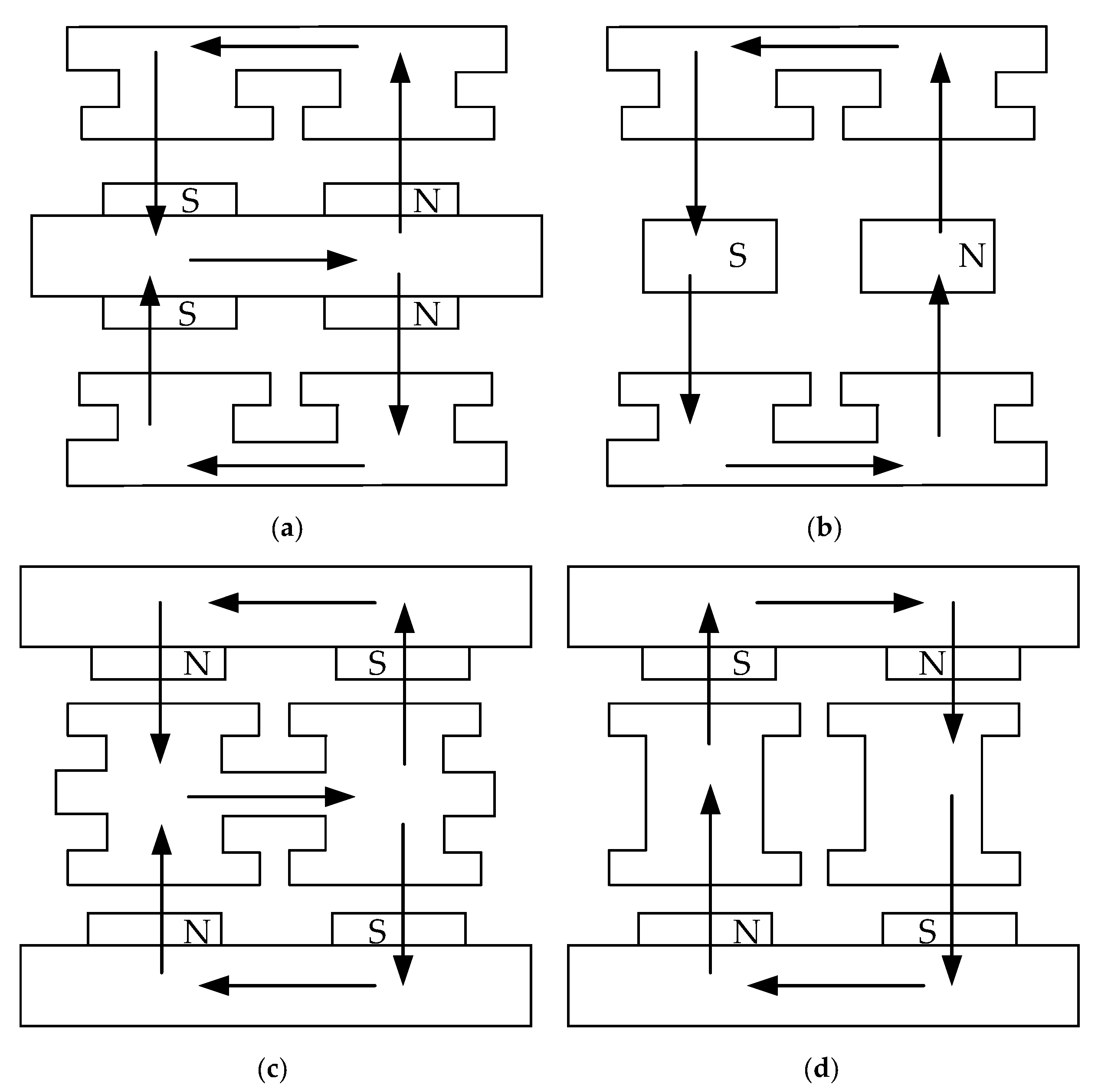
Figure 1 shows several topologies for double-sided AFPMM: (a) double-stator single-rotor (DSSR) with surface-mounted PM, (b) DSSR with interior PM, (c) toroidally wound internal stator (TORUS), and (d) yokeless and segmented armature (YASA). The copper loss, as well as leakage inductance in TORUS and YASA structures, are lower because of the short-end windings. In addition, compared with other topologies, the YASA machine could be a more excellent variant. As the name denotes, YASA has no stator yoke, and the stator consists of the concentrated winding and independent stator core. YASA configuration exhibits a higher winding fill factor, shorter end winding, and limited mutual inductance between different phases because of the modular stator and the absence of the stator yoke [
7]. The stator core weight is also reduced by about 50%, leading to an around 20% increase in the torque density of the motor [
8]. For this reason, the topology of the YASA machine has been widely investigated in recent years.
The YASA structure is comprised of two external rotors and an inner stator. The elimination of the stator yoke results in its special magnetic flux path. As shown in
Figure 1d, the flux starts from the N-pole of one rotor, traverses the double air gap and the stator core, reaches the other rotor, then comes back and forms the whole magnetic loop. Different high-performance ferromagnetic materials can be used to manufacture the stator core, such as lamination silicon steel, soft magnet composite (SMC) [
9,
10], and amorphous alloy [
11]. Among these materials, the amorphous alloy has a small coercivity force and low core loss but has difficult machinability and bad mechanical strength; hence, it is rarely used [
12]. SMC has good magnetic conductivity, high machinability, and isotropic electromagnetic and thermal properties. However, the saturation magnetic flux density of SMC is lower than of lamination silicon steel. Under low-frequency conditions, the core loss is higher [
13]. Considering mainly alternating magnetization existing in the stator core, grain-oriented lamination electrical steel is used to be a better substitution of the YASA stator core [
14].
The middle stator structure also makes the thermal design of the stator a challenge, which limits the output power of the machine. An air-cooling structure is developed for the stator of a 4 kW YASA machine in [
15]. Laminated stator housing made of aluminum alloy is designed to fix the modular stator and decrease additional eddy current. Several inward heat extraction fins are integrated into the stator support to provide a thermal conduction path from the winding to the stator surface. As for high power density applications, especially in electric vehicles, the impact of air cooling is very weak. Therefore, liquid cooling is more suitable for these occasions. Based on [
15], aluminum alloy housing combined with a direct water-cooling system is developed for a 50 kW YASA motor [
13]. Some fins are installed between the slots, and the U-shaped water pipes are placed in the fins to enhance the cooling performance of the stator. The radial ends of the fins are slotted to suppress the additional eddy current. Nevertheless, it is difficult to process such a stator housing. Two annular plastic plates are used to fix the segment stators and the concentrated windings in [
16]. Multiple parallel-connected water pipes are installed near the outer radius of the stator to export the generated heat. Direct oil cooling technology is presented in [
8]. The modular stator is placed in a glass fiber support, and the oil coolant is injected into the housing to decrease the temperature of the stator. Reference [
17] improves the above-oil cooling structure and proposes an oil-immersed, forced cooling system for a 30 kW YASA motor. However, the performance of the stator cooling system still cannot meet the requirement for the high power density of the machine.
With the development of innovative materials and the manufacturing industry, thermal phase-change materials, which release/absorb sufficient energy at phase transition to provide useful heat/cooling, are attracting more and more attention. The heat pipe, as the small size, lightweight, but highly efficient passive phase-change cooling element, has been used in the thermal management system of electric motors. In the current state, the heat pipes have been developed and adapted as an effective thermal management method in the field of the motor. L-shaped flat heat pipes are mounted on the surface of the motor housing to enhance the thermal conduction, and forced air cooling is used to cool the motor [
18]. The experiments show that the heat pipes increase the performance of the cooling system by 25%. Two heat-pipe-based thermal structures, straightly embedded module (SEME) and three-dimensional rounding module (RM) are studied in [
19]. The simulation and experiment of these two structures are based on an air-cooled motor. According to the results, both the steady-state temperature and transient time of the temperature control of the machine can be improved significantly. Meanwhile, SEME can achieve a higher thermal performance than RM under the same operating condition. Heat pipes combined with liquid cooling are designed to maximize heat removal of a PMSM and minimize energy consumption in [
20]. The temperature of the electric motor is maintained at about 70 °C, and 370 kJ energy is saved compared with the traditional liquid cooling method.
However, the precise thermal characteristic of the heat pipe is inaccessible in the above literature. Meanwhile, there is currently no phase-change cooling technology designed for the axial flux machines, especially the YASA machines. A novel stator cooling structure combined the flat heat pipe with the housing water-cooling for a 60 kW YASA machine is proposed in this paper. The remainder of the article is organized as follows.
Section 2 describes the stator cooling structure of a 60 kW YASA motor. In
Section 3, the principle of the heat pipe is given, and an experimental platform is built to test the relationship between the thermal conductivity of the heat pipe and temperature. The thermal property of a flat heat pipe, for which copper is the casing and water is the working medium, is obtained by the platform. Then, In
Section 4, different housing cooling methods are compared, and the validity of the proposed cooling structure is confirmed by CFD simulation. Finally,
Section 5 draws the conclusion.
2. Stator Cooling Structure of YASA
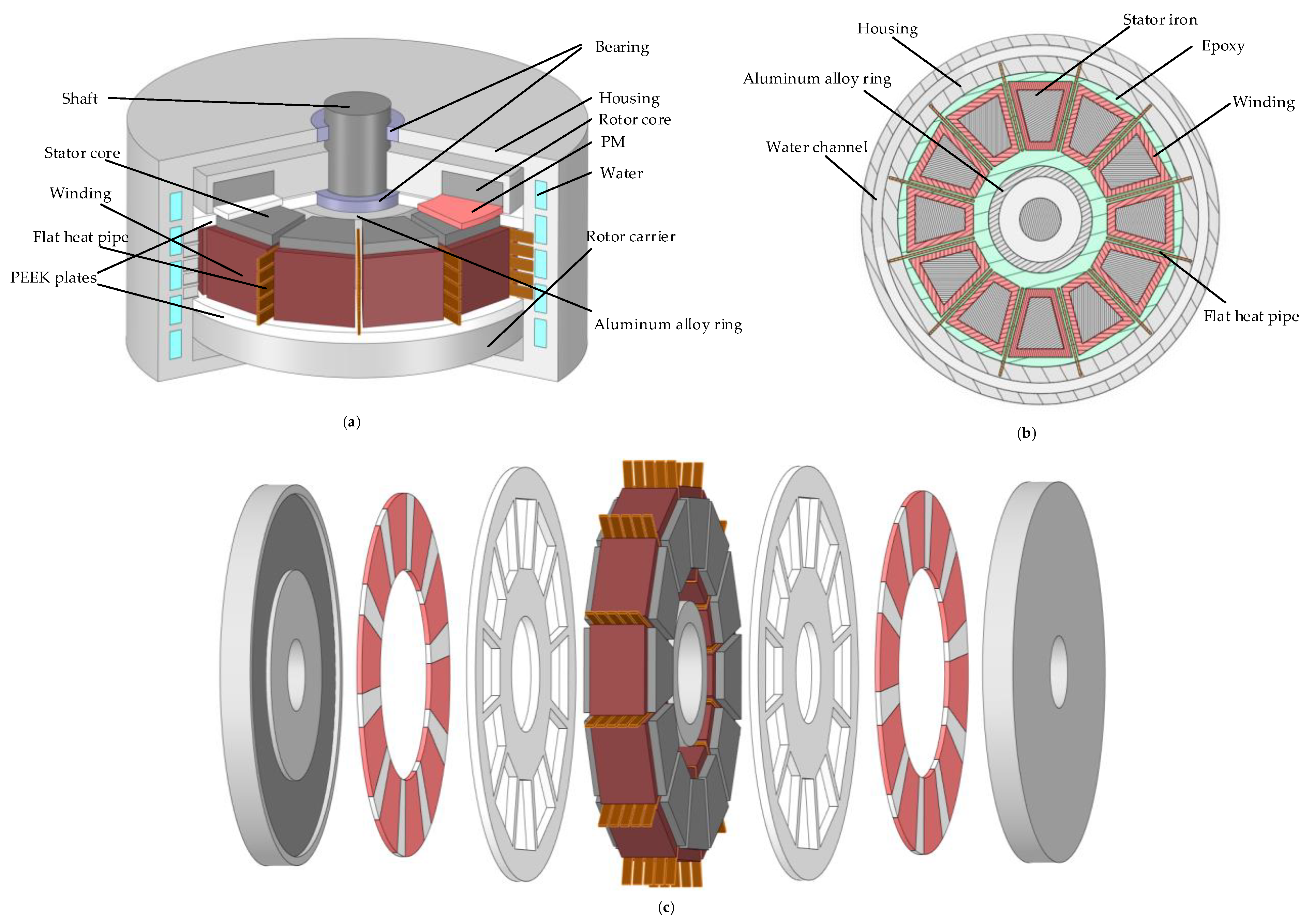
The configuration of the YASA machine is shown in
Figure 2. The proposed motor has three phases, 10 poles, and 12 slots. Each rotor consists of 10 surface-mounted PMs and an iron core with cylindrical lamination steel. The stator is modular, includes 12 individual iron cores and 12 concentrated windings. Considering the mechanical strength and processing difficulties, the rotor core is made of grain-oriented lamination electrical steel. To reduce the eddy current loss in the permanent magnets, they are divided into three segments in one pole. The key parameters of the investigated machine are shown in
Table 1.
In order to achieve an effective thermal dissipation for the proposed YASA machine, it is crucial to adopt an appropriate cooling method. Generally, three active thermal management methods, natural cooling, forced air-cooling, and forced liquid-cooling, are commonly applied in the electric motor domain [
21]. Without the employment of additional enhanced cooling devices, natural cooling uses the airflow generated naturally during the motor operation to dissipate the heat from the motor components to the surrounding environment. The cooling efficiency of natural cooling is unsatisfactory. Therefore, it is always suitable for low- or medium-power density motors. The forced air-cooling uses the fan or other equipment installed on the motor to enhance the air-flow and then exchange the heat to the ambient environment effectively. Compared to natural cooling, the forced air-cooling can provide more coolant flow and achieve larger heat dissipation. However, the cooling capacity of the fan-cooling is limited. Another defect is that the forced air-cooling will produce acoustic noise on high-speed occasions. Some techniques are used to reduce the noise, such as using an optimized fan blade [
22] or a new composite material [
23]. Hydrogen is considered to be a more appropriate coolant substitute than air, as it has higher thermal conductivity, better-forced heat convection, and lower density [
24]. The windage losses can be reduced to one-tenth when the coolant medium changes from air to hydrogen. However, the purity of hydrogen is very important [
25]. The experimental test has proven that a gas mixture of hydrogen combined with air is explosible, especially the percentage of hydrogen below 72% [
26]. For safety’s sake, the proportion of hydrogen in a gaseous mixture must be over 90%.
As for the cooling approaches of high power density motors, forced liquid-cooling methods are widely used. Via pump or other additional equipment, the forced liquid-cooling drives the liquid cooling medium, such as water and oil, flowing through the designed channel to transfer the heat generated by the motor component to an external heat exchanger. Water is an excellent coolant for the reason that it has the highest thermal conductivity in all fluids. The incrustation will be produced in the case of long-term operation. Water cooling also suffers from corrosion and leakage. The engine oil has better dielectric constant, insulative, and security than water. However, its cost is notably higher. Undeniably, the water-cooling method is the most commonly forced liquid-cooling approach because of its low-cost and easy manufacturing process. Taking the tradeoff by security, cost, and efficiency of different thermal management approaches, the housing forced liquid-cooling method, in which the coolant cooling channel is located in the housing, is used to remove the heat generated by the stator component of the YASA machine in this paper.
In addition, the stator component is assembled in the stator support to meet the mechanical and installation requirements. The detailed requirements about the stator support construction of the YASA machine are given in [
16]. It is introduced that a stator support construction of the YASA machine should be designed to achieve the following targets:
- (1)
the elastic modulus and the yield stress of support should be very high to avoid the asymmetric air gap, which is mainly caused by the large axial magnetic force between the middle stator and the two external rotors.
- (2)
the induced eddy current loss must be limited to reduce the heat source and increase the total efficiency.
- (3)
a high working temperature and low thermal expansion coefficient are required to guarantee the safe operation under extreme conditions as far as possible.
To meet the above demands, a stator carrier made of an excellent plastic material named polyetheretherketone (PEEK) is presented in [
16]. PEEK has low density, outstanding mechanical strength, high thermostability, and workability. As a plastic material, it also possesses neither electrical nor magnetic conductivity. Therefore, PEEK is one of the ideal materials for stator support.
In this paper, in consideration of the fixation improvement of stator modules and the accuracy enhancement of the rotor assembly, the ultimate cooling structure is illustrated in
Figure 3. The stator cores and concentrated windings are embedded into two plates made of PEEK for full fixation. Two PEEK plates are bolted to the protruding middle part of the inner surface of the housing. Additionally, an aluminum alloy ring is placed inside to secure the bearing to avoid an unbalance air gap. The rotor core and PMs are installed in the rotor carrier, which is made of aluminum alloy. In order to reduce the additionally induced eddy current loss of the rotor carrier, PEEK is filled in the gap between PMs.
Housing water-cooling is applied to remove the heat generated by the total YASA machine. To improve the heat transfer efficiency of the stator to the housing water-cooling, several heat pipes are equally installed on the internal wall of the housing and inserted in the gap between the stator modules. Instead of a round heat pipe, the flat one, which shape is like a long narrow strip, is used in the YASA machine considering the limitation of the gap space between the stator modules. As a result of the inevitable manufacturing and assembly tolerances, the thickness, height, and length of the flat heat pipe are 2 mm (one-third of the total gap width), 8 mm, and 85 mm, respectively. The remainder of the stator support is impregnated with epoxy resin, which can not only enhance the mechanical strength of the machine significantly but also reduce the thermal resistance and increase the effectiveness of the heat transfer.
The heat sources of the motor consist of copper loss, core loss, and windage loss. The copper loss is caused by the resistive component of the coil winding and is calculated by the following equation:
where
is the rated phase current;
is the phase resistance.
The core loss is caused in the iron core due to alternation or rotation magnetization and can be typically calculated by the classical Steinmetz equation [
27]:
where
,
, and
are the hysteresis loss, eddy current loss, and excess loss, respectively;
is the coefficient of the hysteresis loss, which is related to the property of the material;
is the eddy current loss coefficient;
is the coefficient of the excess loss;
and
are the electrical conductivity and the density of the iron core;
and
are dimensionless coefficients related to magnetic properties;
and
are the sectional area and thickness of silicon iron.
The windage loss refers to the loss caused by the relative friction between the rotor and the surrounding air. The calculating formula is given in [
28]:
where
is the roughness coefficient, and the value is 1.0 for smooth surfaces and 2.5 for axially slotted surfaces;
is the friction coefficient;
is the density of air;
is the angular velocity of the rotor;
is the length of the cylinder; and
is the rotor radius.
Considering the accuracy and efficiency, copper loss and windage loss are estimated by Equations (1) and (3). The core loss is obtained using the software ANASYS Maxwell. After calculation, the losses with different components of the machine are shown in
Table 2.
3. Test Experiment for Thermal Property of the Heat Pipe
The heat pipe is a heat-transfer device that combines the principles of both thermal conductivity and phase transition to transfer the heat between two solid interfaces effectively [
29]. A heat pipe consists of a sealed casing, a porous wick structure, and a vapor channel. Additionally, there is a small quantity of working medium in the vapor channel, such as water and methanol [
30]. As shown in
Figure 4, the heat pipe can be divided into two parts, the evaporation section (hot end) and the condensation section (cold end). In the evaporation section, external heat passes through the shell and porous wick structure by heat conduction, making working fluid in the vapor channel vaporize. The resulting vapor pressure or gravity drives the vapor into the condensation section. Then, the vapor condenses and releases its latent heat of vaporization by active cooling methods, such as air cooling or water cooling. The wicking effect created by the menisci in the porous wick structure pumps the condensed medium back to the evaporator. In this way, the heat pipe can continuously transfer the heat from the evaporator to the condenser and dissipate heat efficiently.
As a result of a large amount of heat exchange during the phase change process of the working medium, the equivalent heat conductivity of the heat pipe can reach hundreds of times more than that of copper, which is the metal with the best thermal properties. To improve the efficiency of the CFD simulation, the heat pipe is equivalent to a metal bar with constant high-thermal-conductivity [
19]. However, the main working principle of the heat pipe is the endothermic phase change of the internal working medium. As a result, its thermal conductivity will be affected by the operating temperature. When the ambient temperature is too low to cause the phase change of the working fluid, the heat pipe exhibits the thermal conductivity of its metal shell. As the temperature increases, the working fluid at the evaporation end gradually changes from liquid to gas, and when the heat pipe starts, its thermal conductivity gradually increases. When the liquid working fluid comes to the evaporator, it will be converted to a gaseous state immediately, which means that the working fluid is completely in circulation. In this case, the heat pipe performance reaches its limitation. If the surrounding temperature continues to increase, the heat pipe could be damaged. In conclusion, the relationship between the thermal property of the heat pipe and the temperature need to be measured accurately.
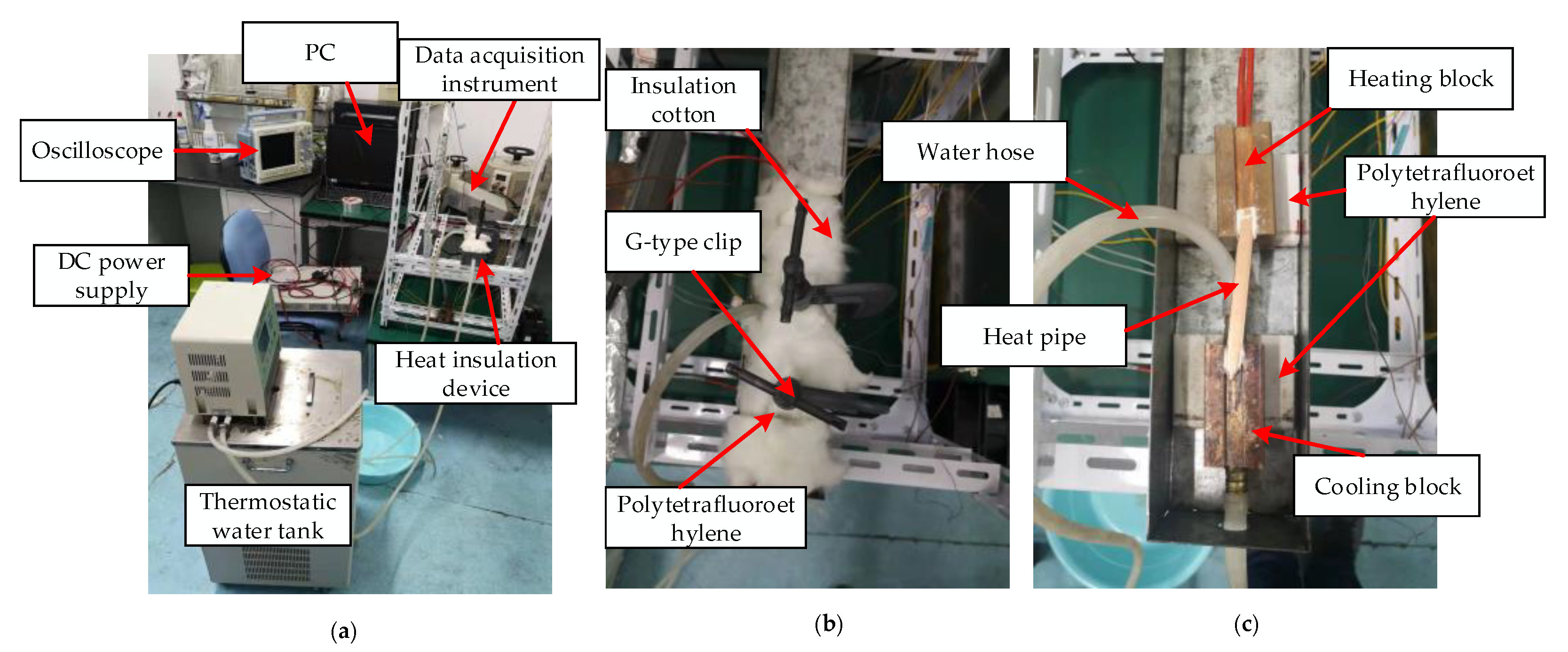
In this paper, an experimental platform is built to obtain the thermal characteristic of the heat pipe, as shown in
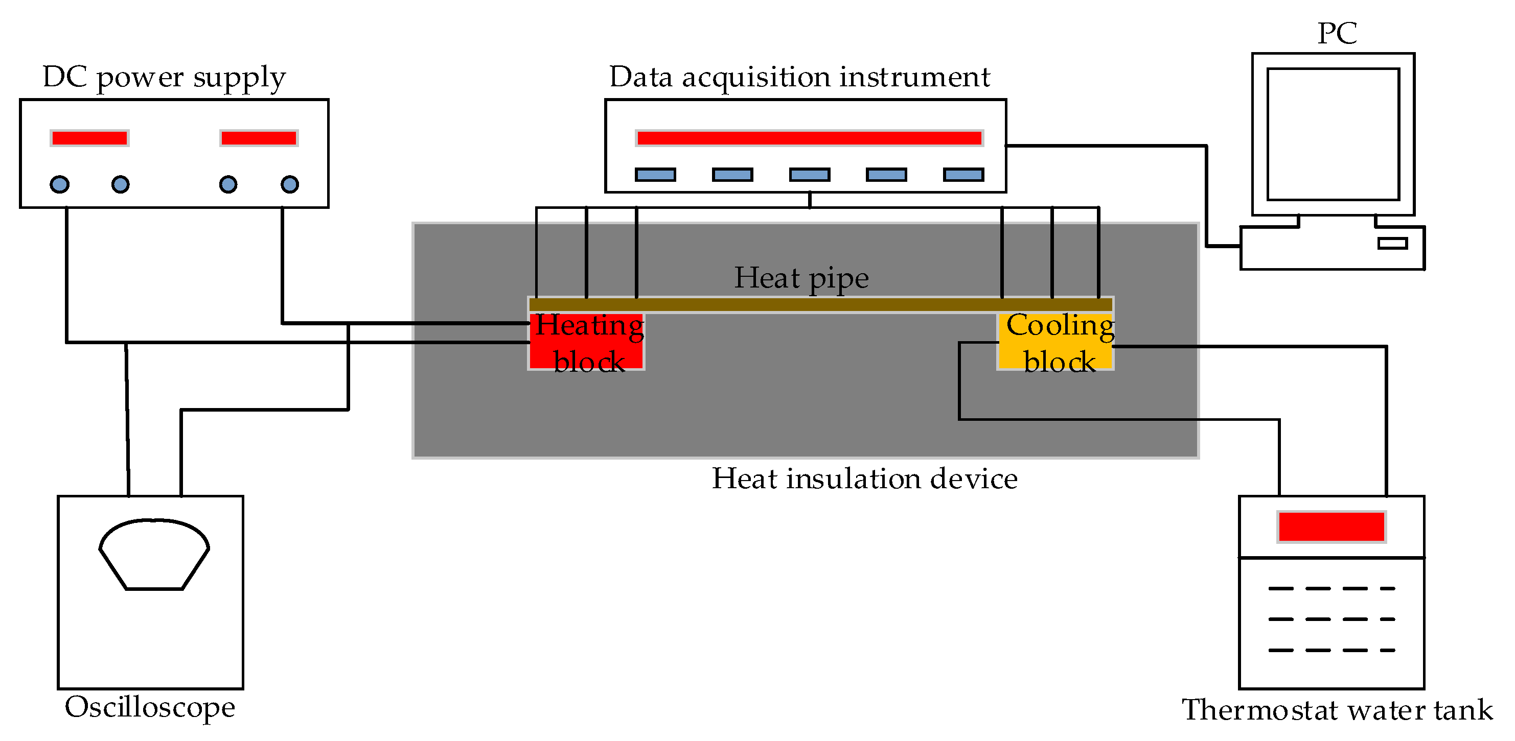
Figure 5. Two blocks made of red copper are used to provide the heating and cooling conditions for the heat pipe. The heat pipe to be tested is placed on the blocks. A heating rod, which is powered by the DC power supply, is inserted into the heating block to generate heat. To keep constant cooling convection, the cooling block is connected to a thermostatic water tank through a water hose. Thermal grease is applied between the blocks and the heat pipe to reduce the contact thermal resistance and guarantee consistency in the heat transfer process of the heat pipe. The blocks are fixed in a heat insulation device by a G-type clip to prevent interference from the ambient environment. The polytetrafluoroethylene (PTFE) board, which has good adiabaticity, is used to avoid heat loss. The insulation device is filled with insulation cotton to insulate from the heat. Thermocouples are placed on the condensing end and the evaporating end of the heat pipe to measure the temperature. An oscilloscope is used to measure the current and voltage of the power supply. The schematic diagram of the experimental process is depicted in
Figure 6.
The flat heat pipe used in this paper is made of flattened copper tubes with sintered copper capillary wick and water as the working fluid medium with a filling ratio of 30%. The data acquisition instrument is 34970A, made by Agilent. The temperature thermostat bath is X0DC-1015 made by Nanjing Xianou Instrument Manufacturing Company, Nanjing, China.
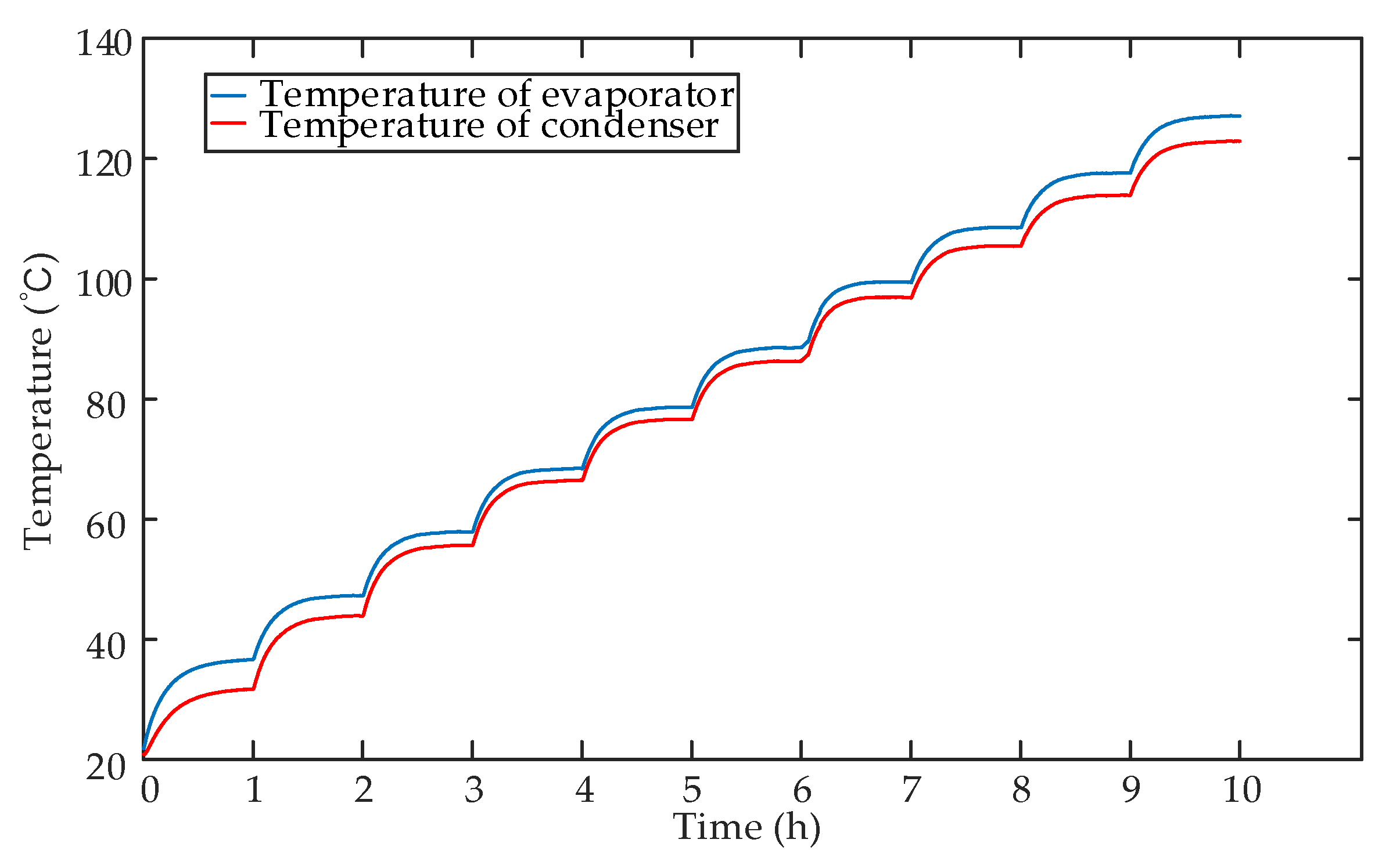
To measure the thermal performance of the heat pipe accurately, the sampling plan with 3 thermocouples for the evaporating section and 3 thermocouples for the condensing section is adopted. The average value of measured temperatures is calculated as the final temperature. Considering each heat pipe dissipates 30 W under the rated condition, 10 different power levels from 5 W to 50 W are tested in the experiment. Each power level is maintained for 1 h to stabilize the temperature, and the temperature is recorded every 5 s. The experimental results are shown in
Figure 7.
The equivalent thermal conductivity of the heat pipe is calculated according to the following formula:
where
,
,
,
,
,
, and
are the thermal resistance, the temperature of the evaporator, the temperature of the condenser, the input power, the length of the heat pipe, the cross-sectional area of the heat pipe, and the coefficient of thermal conductivity of the heat pipe, respectively.
The thermal property of the heat pipe after the calculation is listed in
Table 3. The mathematical relationship between the equivalent thermal conductivity of the heat pipe and the temperature is obtained for CFD simulation. Hence, the polynomial function curve fitting method based on interpolation is adopted to regress the thermal property of the heat pipe. Taking the average temperature of the evaporating section and the condensing section
as the independent variables, three polynomial curve fitting methods, 3rd, 4th, and 5th order, are used and compare the effect of the fitting. The fitted curves of the equivalent thermal conductivity with the average temperature are shown in
Figure 8, and the fitting functions are given as follows
The goodness evaluation of three fitting functions is given in
Table 4. From
Figure 8 and
Table 4, a conclusion can be made that the 4th order polynomial function is accurate enough to fit the thermal performance of the heat pipe. It also can be observed that the equivalent thermal conductivity of the heat pipe first increases and then decreases with the temperature. Since the boiling point of the working medium is 100 °C, when the temperature range is within 80–110 °C, the equivalent thermal conductivity of the heat pipe reaches the maximum. The maximum value is about 70,000 W·(m·K)
−1, which is 180 times the thermal conductivity of copper.
4. The thermal Performance of the Cooling Structure
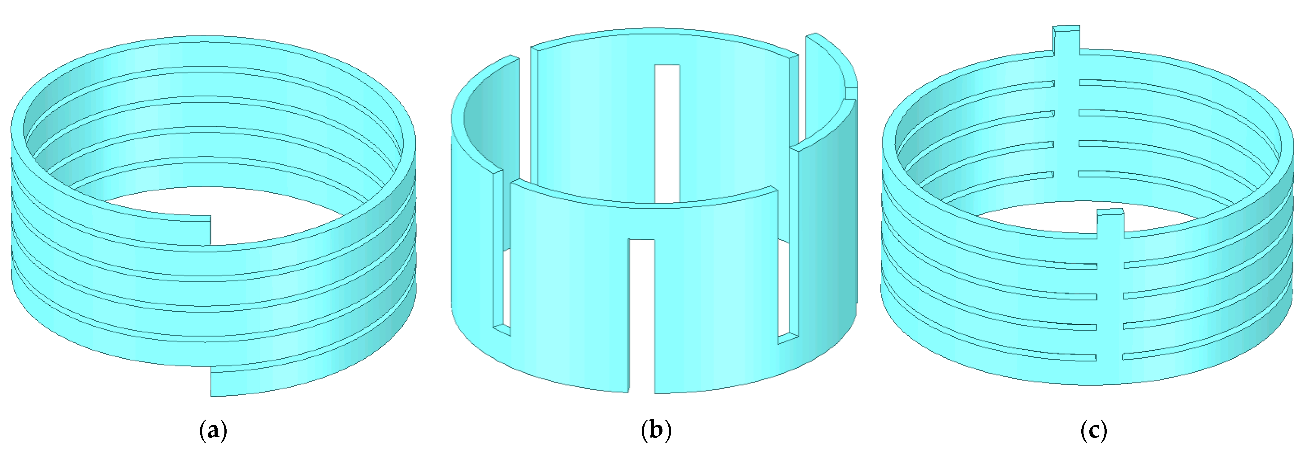
For housing cooling, three types of channels, spiral, axial, and parallel channels, can be chosen [
31]. As shown in
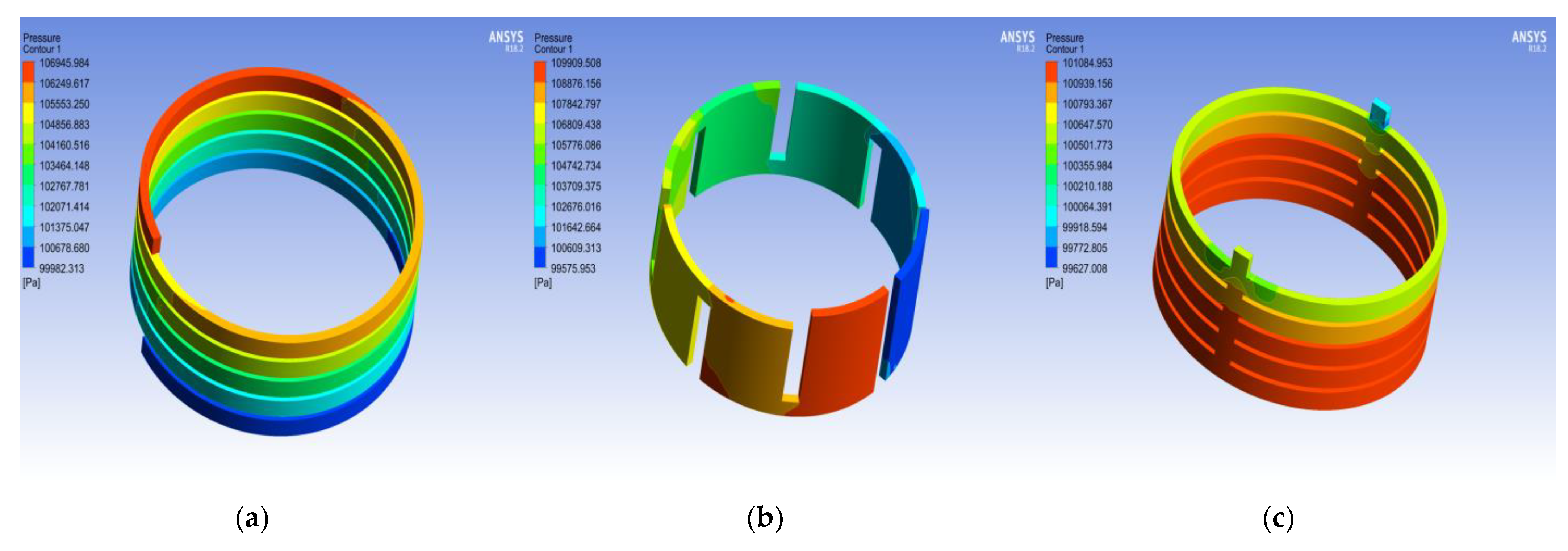
Figure 9, the water in the spiral channel flows spirally from one end of the frame to the other to transfer the inner heat of the housing to the ambient environment. In an axial housing channel, the fluid coolant flows along the axial direction, like a zigzag-type road. A parallel channel is comprised of several individual and parallel pipes, and the coolant in parallel pipes flows annularly.
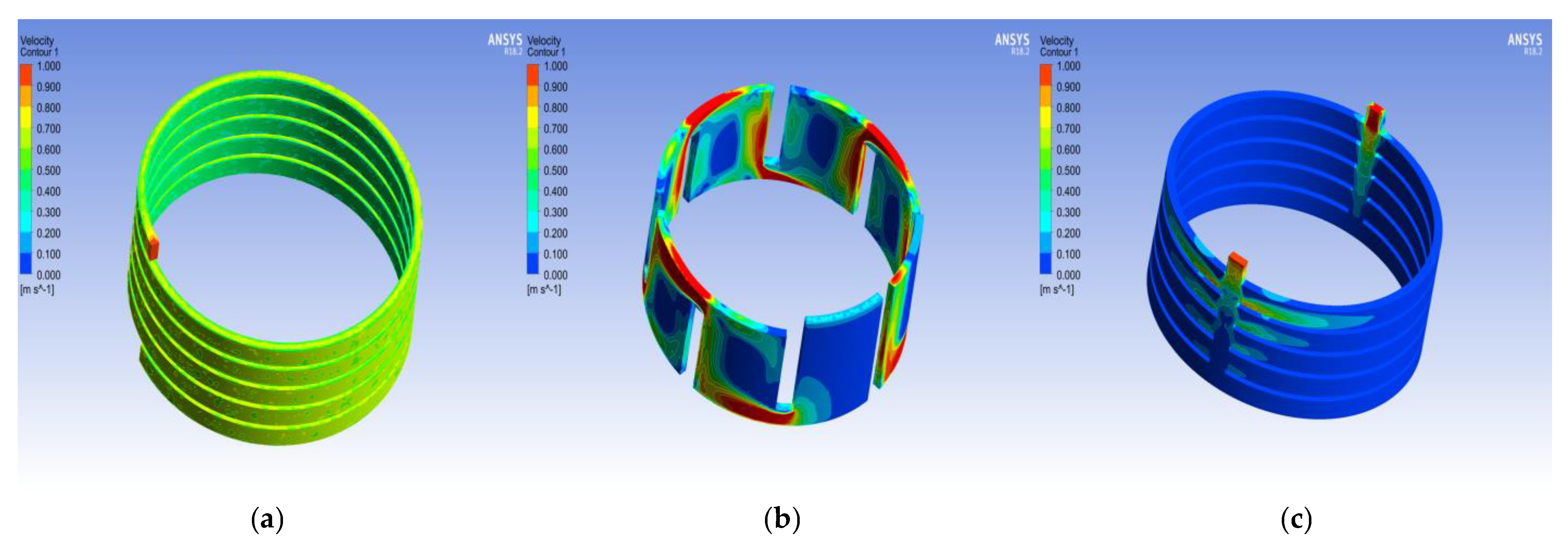
The comparison of their pressure and velocity distribution is presented in
Figure 10 and
Figure 11, respectively.
Table 5 gives the characteristic of the inlet and outlet with three structures. Velocity inlet boundary and pressure outlet boundary are defined as the boundary conditions. The temperature of the inlet water is set at 25 °C, and the pressure of the outlet is set at 100,000 Pa, which is the barometric pressure. The quantity of coolant flow is set at 0.2 kg/s to compare their properties under the same condition. The fluid volume and contact area with casing for three types of housing cooling structures also bring into correspondence with each other.
From
Figure 10 and
Figure 11, some conclusions are made. The pressure distribution of the spiral and axial channels gradually decreases from the inlet to the outlet. However, for the parallel one, different pressure distributions are presented in different parallel pipes. The pressure in the pipe near the inlet and outlet is lower than the ones far from them. Due to the unevenly distributed pressure for a parallel channel, the velocity distribution is extremely unbalanced. The velocity in the outermost pipe shows about one-tenth compared with the nearest counterpart. It also can be observed in
Figure 10b that an amount of eddy-flow exists in the axial housing channel, which has a negative influence on the flow resistance and the thermal performance of the cooling structure.
The loss of pressure drop between the inlet and the outlet is usually used to assess the energy consumption of maintaining the cooling system. In
Table 5, it can be noticed that the loss of pressure drop of the axial channel is the highest among all three housing cooling structures, whereas the parallel channel is the lowest. Hence, some characteristics of them can be summarized as follows:
- (1)
the coolant in the axial housing channel flows along a zigzag path so that the flow resistance and the pressure drop are the largest in all three structures. An amount of eddy-flow also exists inside the channel, which is unbeneficial to the thermal performance of the cooling system.
- (2)
in the parallel channel, the fluid in different pipes flows independently, which makes the flow resistance, and the loss of pressure drop is the lowest of all three structures. However, the pressure and velocity of the different pipes are extremely unbalanced.
- (3)
the liquid in a spiral jacket flows circumferentially, causing the flow resistance and the loss of pressure drop between axial and parallel channels. The pressure and velocity distribution decrease gradually. In addition, its wall heat transfer coefficient is the best of all three structures. Therefore, the spiral channel is adopted as the housing cooling method in this paper.
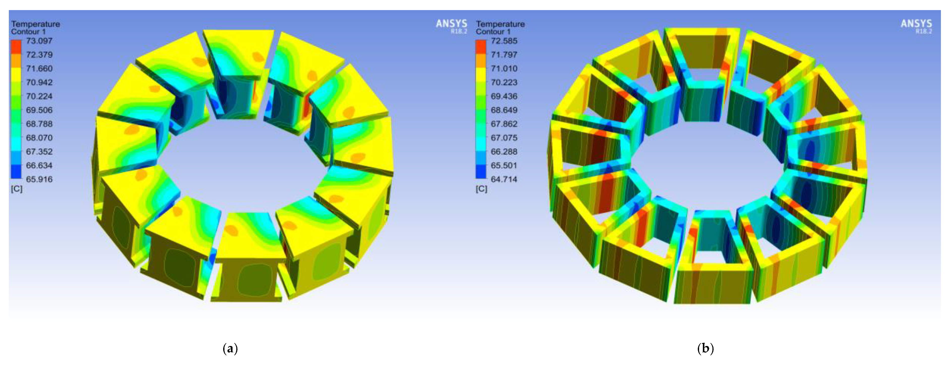
The material properties of the motor components are given in
Table 6. The numerical simulation is carried out using the ANSYS Fluent software because of its advanced physics capabilities, high accuracy, and ease of use. The temperature distribution with the stator of the YASA machine is shown in
Figure 12. It can be noticed that the temperature distribution is uniform, and the maximum temperature difference is 8 ℃. In addition, the average temperature of stator cores and windings are calculated as 70.1 ℃ and 69.2 ℃, respectively. Therefore, the proposed cooling system can accelerate the release of heat from the stator efficiently.
5. Conclusions
In this paper, a novel stator cooling system for the yokeless and segmented armature axial flux machine combining the flat heat pipe with the housing cooling method is presented. In order to reduce the additional loss, the stator components are held with two plates made of PEEK and fixed in the housing. The flat heat pipes are installed in the gap between the stator modules to accelerate the heat transfer from the stator segments to the housing. By impregnating with the epoxy resin of excellent mechanical and thermal properties, the stator components are bound together firmly.
Subsequently, an experimental platform is designed to measure the thermal properties of the heat pipes. The thermal conductivity of a flat heat pipe, which is made of flattened copper tubes with a sintered copper capillary wick, and water as the working fluid medium with a filling ratio of 30%, is obtained by the proposed platform. The equivalent thermal conductivity of the heat pipe is increased and then decreased with the variation of the temperature. When the temperature range is about 80 °C~110 °C, the equivalent thermal conductivity reaches its maximum, about 70,000 W·(m·K)−1. In addition, three types of housing channels, the spiral, axial, and parallel channels, are compared under the same condition. To tradeoff the energy consumption, flow, and thermal characteristic of different housing cooling methods, the spiral cooling channel is adopted in this paper.
Finally, the validity of the proposed cooling structure is verified by CFD simulation. The result shows that the average temperature of the stator cores and windings are 70.1 °C and 69.2 °C, respectively. It is proven that the proposed structure can increase the heat transfer efficiency of the stator and improve the temperature distribution of the stator sufficiently. Furthermore, the mechanical stability of the above construction also needs to be confirmed.


