Article

Investigation of the Torque Production Mechanism of Dual-Stator Axial-Field Flux-Switching Permanent Magnet Motors

1
School of Electrical Engineering, Southeast University, Nanjing 210096, China
2
College of Energy and Electrical Engineering, Hohai University, Nanjing 211100, China
*
Author to whom correspondence should be addressed.
Energies 2021, 14(17), 5498; https://doi.org/10.3390/en14175498
Submission received: 21 July 2021 / Revised: 30 August 2021 / Accepted: 31 August 2021 / Published: 3 September 2021

Abstract

:
This paper studies the torque production mechanism of the dual-stator axial-field flux-switching permanent magnet (DSAFFSPM) machine. Due to the double-sided slotting design of such topology, more resultant air-gap working harmonics in the air-gap flux density are responsible for the torque production and the stator air-gap permeance is especially considered in the investigation. Based on the magnetic force (MMF)-permeance model, the composition and difference of the air-gap working harmonics are demonstrated. The DSAFFSPM machine torque contributions of the main working harmonics are analyzed theoretically and quantified by finite element analysis (FEA). The influence laws of the parameters on the working harmonics are shown and this effectively improves the motor operation performance. Finally, some experiments on the DSAFFSPM machine are carried out to validate the analytical and FEA results.

1. Introduction

With the merits of high torque density and high efficiency, permanent magnet (PM) machines have been extensively investigated and widely applied in many industry fields, such as in electrical vehicles, wind power generations, and traction systems [1,2,3,4]. According to the different placements of PMs, PM machines can be divided into rotor-PM [5] and stator-PM [6,7] machines. As a special topology of stator-PM machines, flux-switching permanent magnet (FSPM) machines have attracted much attention because of their characteristics such as good heat dissipation, high rotor robustness, easy manufacturing, and highly sinusoidal back-EMF waveform [8,9,10].
In recent years, large numbers of studies on FSPM machines have attached considerable attention to the proposal of new topologies. Different stator tooth configurations, such as E-core, U-core, and C-core stator structures, have been deeply developed and widely investigated. The performance comparison of E-core, U-core, C-core, and conventional FSPM machines was studied in [11]. The research results of [12] showed that the torque of the E-core FSPM machine is about 15% larger than that of the conventional FSPM machines because such stator has auxiliary teeth which can provide an additional magnetic path to pass. Although the spoke structure in FSPM machines can further improve the torque density due to the flux focus effect, it also brings about the concern of the pole flux leakage issue. Consequent-pole (CP) PM designs have been proposed to cope with the leakage flux. Compared with the conventional FSPM machines with N-S poles, CP PM machines have homopolar PMs (either N-pole or S-pole). Such arrangements can provide higher back-electromotive force (EMF) and larger torque capability due to the asymmetric air-gap field distribution [13,14].
From the perspective of the direction of the main magnetic circuit, FSPM machines can be divided into radial, axial, and linear-motors. Among them, the axial-field FSPM (AFFSPM) machine is considered suitable for in-wheel motors due to its advantages featuring high efficiency, high power density, and its compact-flat design [15,16,17]. E-core and U-core dual-stator AFFSPM (DSAFFSPM) machines have been proposed to have great torque capability, high fault tolerance, and good thermal management [18,19,20]. In [21], a comparison of the above two kinds of DSAFFSPM machines was made and demonstrated to be even more heavily tilted towards performance evaluation and numerical difference. In [22], the operation principle of DSAFFSPM machines was analyzed based on the modulation principle using a simple air-gap magnetomotive force (MMF)-permeance model. However, only the rotor slotting effect was considered in this study, which is not accurate enough.
Although various DSAFFSPM machines were extensively developed and investigated [15,16,17,18,19,20,21,22], the existing research still has the following shortcomings. On the one hand, the in-depth understanding of the torque generation mechanism of DSAFFSPM machines has not been reported yet. On the other hand, the performance improvements have been always carried out through the parameterization of FEA simulation. In this context, the underlying torque production mechanism of the DSAFFSPM machines is investigated considering the double-sided slotting effect. After the torque contribution of each working harmonic is obtained, the direct relationship between the parameters and the air-gap working harmonics is revealed to effectively improve the motor performance.
The organization of this paper is as follows. In Section 2, the experimental and theoretical methods of the DSAFFSPM machine are presented. The structure introduction, operation principle, and torque production mechanism of the topology are included in this section. In Section 3, the results and discussion of the above theoretical analysis are shown. In this section, both the analytical and the FEA results of the torque contributions of the main-order working harmonics are illustrated and compared. Subsequently, the influence laws of some designed parameters on the air-gap working harmonics are clearly revealed. Finally, the manufactured 6/10 E-core DSAFFSPM machine is presented to validate the FEA and analytical results. In Section 4, some conclusions of the investigation are clearly summarized.

2. Experimental and Theoretical Methods

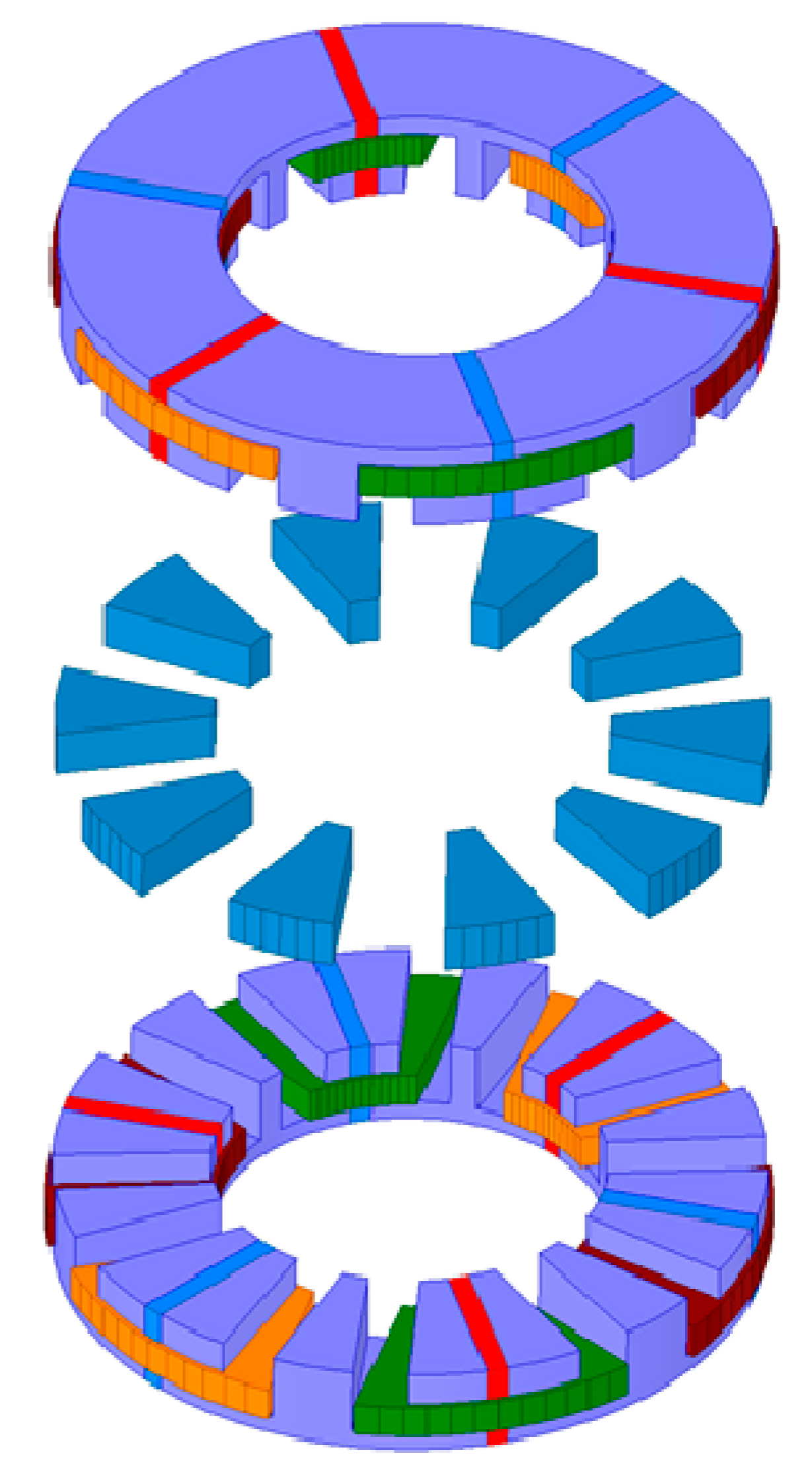
2.1. Machine Topology

With the purpose of reducing PM utilization and improving the torque capability, the 6/10 DSAFFSPM machine with E-core is proposed in Figure 1. Three parts are included in the 6/10 E-core DSAFFSPM machine, with double stators and a rotor sandwiched in between. The stator consists of several identical iron modules with salient teeth. Between two adjacent stator modules, circumferentially magnetized permanent magnets are placed. The rotor has a simple structure and is composed of several evenly distributed iron teeth. In Figure 2, the stator and rotor diagram, as well as their corresponding air-gap permeance and PM MMF, are presented. In the following analysis, Z s and Z r denote the number of the stator modules and rotor salient teeth, respectively. The parameters p m and p a are the pole-pair numbers (PPN) of PMs and the armature windings, respectively. The equation p m = Z s / 2 holds in this paper.

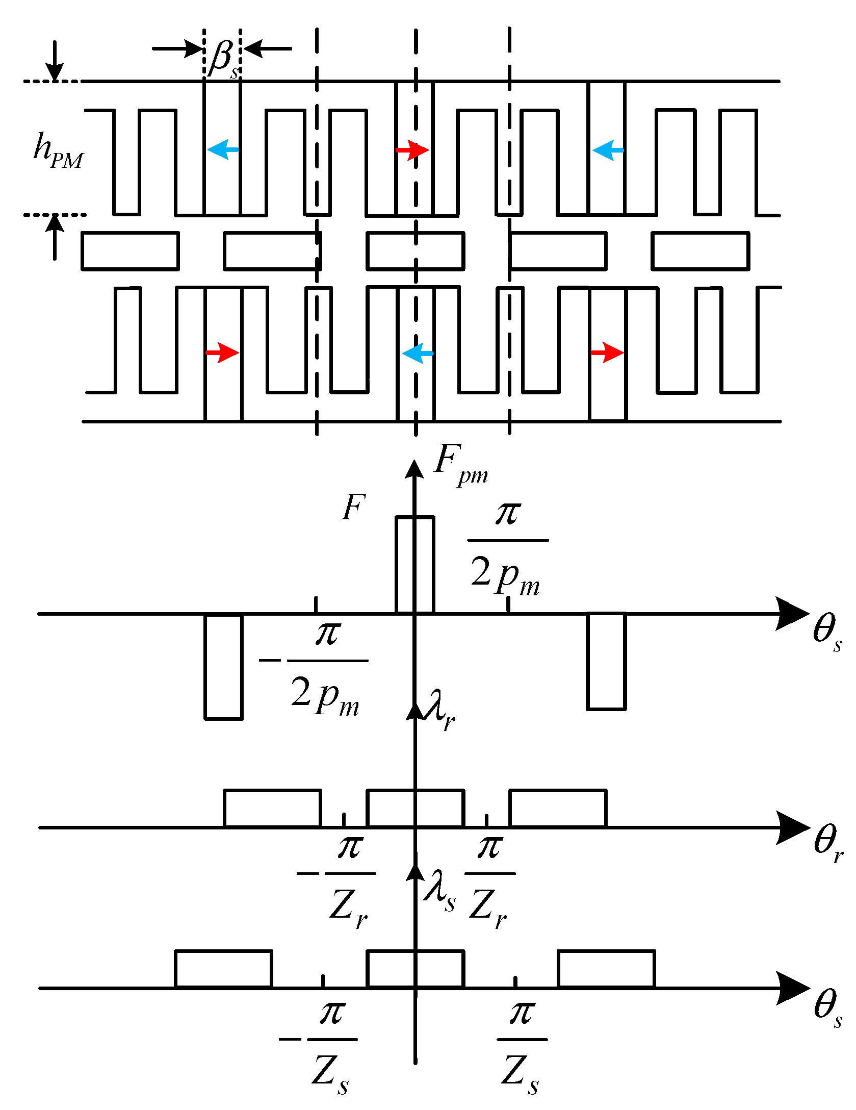
2.2. Operation Principle and Torque Production Mechanism

As FSPM machines can be regarded as a special topology of stator-PM flux-modulation machines, an air-gap MMF-permeance model can be utilized to demonstrate the working principle of the DSAFFSPM machine [23]. For this doubly salient structure, both stator and rotor permeances should be considered. The air-gap permeance per unit area can be obtained from Figure 2 and expressed as [24]
λ g ( θ s ) = δ λ s ( θ s ) λ r ( θ r ) μ 0
where δ is the air-gap length amd μ0 is the vacuum permeability. λ s ( θ s ) and λ r ( θ r ) are the air-gap stator and rotor permeance functions, respectively. Their corresponding Fourier decomposition functions are given as
λ s ( θ s ) = λ s 0 + i = 1 λ s i cos ( i Z s θ s )
λ r ( θ r ) = λ r 0 + j = 1 λ r j cos ( j Z r θ r ) ,   θ r = θ s θ 0 Ω r t
where λ s 0 and λ r 0 are the DC-component of the stator and rotor permeances, respectively; i and j are the Fourier orders of the stator and rotor permeances, respectively; λ s i and λ r j are the ith stator and jth rotor permeance coefficients, respectively; θ s and θ r are the stator and rotor position angles respectively; θ 0 is the initial position of the stator; and Ω r is the mechanical angular speed. According to (1)–(3), the air-gap permeance can be rewritten as
λ g ( θ s ) = δ μ 0 λ s 0 λ r 0 + δ μ 0 λ r 0 i = 1 λ s i cos ( i Z s θ s ) + δ μ 0 λ s 0 j = 1 λ r j cos ( j Z r ( θ s θ 0 Ω r t ) ) + 1 2 δ μ 0 j = 1 i = 1 λ s i λ r j cos [ ( i Z s ± j Z r ) θ s ( j Z r ( θ 0 + Ω r t ) ]
The PM MMF in Figure 2 can be expressed as
F p m ( θ s ) = k = 1 F k sin ( k p m θ s )
where k is the Fourier orders of the PM MMF and Fk is the kth PM MMF coefficients.
In obtaining the air-gap permeance and PM MMF, the air-gap flux density is given as
B g ( θ s , t ) = F p m ( θ s ) λ g ( θ s ) = δ μ 0 λ s 0 λ r 0 k = 1 F k sin ( k p m θ s ) + 1 2 δ μ 0 λ r 0 k = 1 i = 1 F k λ s i sin [ ( k p m ± i Z s ) θ s ] + 1 2 δ μ 0 λ s 0 k = 1 j = 1 F k λ r j sin [ ( k p m ± j Z r ) θ s ( j Z r ( θ 0 + Ω r t ) ] 1 4 δ μ 0 k = 1 j = 1 i = 1 F k λ r j λ s i sin [ ( k p m ± j Z s j Z r ) θ s ( j Z r ( θ 0 + Ω r t ) ]
The steady torque can be produced only if the frequency of the current matches the pole-pair number of the harmonics of the no-load flux density. For instance, when j = 1, the frequency of the current is Z r and the PPN of the harmonics of the no-load air-gap flux density is Z r ± k p m . Afterwards, the steady torque is obtained and the Z r ± k p m th harmonics of the no-load flux density can be regarded as working harmonics. Note that when j is chosen as 1, the working harmonics in (6) just satisfy:
n p a ± Z s = n ( Z r Z s 2 ) ± Z s
Equation (7) denotes anything in these working harmonics that is the slot harmonic of another working harmonic. These working harmonics share the same winding factor as that of the Zs/Pa-slot/pole combination. For this reason, in order to obtain the steady torque, the air-gap flux density can be rewritten as
B g ( θ s , t ) = F p m ( θ s ) λ g ( θ s ) = B 1 k + B 2 k i + B 3 k + B 4 k i δ μ 0 λ s 0 λ r 0 k = 1 F k sin ( k p m θ s ) + 1 2 δ μ 0 λ r 0 k = 1 i = 1 F k λ s i sin [ ( k ± 2 i ) p m θ s ] + 1 2 δ μ 0 λ s 0 λ r 1 k = 1 F k sin [ ( k p m ± Z r ) θ s ( Z r ( θ 0 + Ω r t ) ] 1 4 δ μ 0 λ r 1 k = 1 i = 1 F k λ s i sin [ ( ( k ± 2 i ) p m Z r ) θ s ( Z r ( θ 0 + Ω r t )
In Equation (8), B 1 k and B 2 k i are both stationary parts of the flux density harmonics. The steady torque generation cannot be achieved with such stationary harmonics. Meanwhile, B 3 k and B 4 k i are the rotary parts of the flux density harmonics, which are responsible for the generation of steady torque, and can be called working harmonics. The amplitude of each working harmonic is related to the first-order harmonic of the rotor; thus, the augment of the first rotor air-gap permeance is of great importance in the process of design optimization. The desired air-gap flux density can be obtained by changing the corresponding PM MMF and stator air-gap permeance, accordingly adjusting the motor structure.
After deriving the expression of the air-gap flux density, the back-EMF expression can be given as
e p h ( t ) = d d t ψ A ( θ s , t ) = d d t B g ( θ s , t ) N ( θ s ) d S = δ μ 0 N p h D g l s t k λ s 0 λ r 1 k = 1 Z r k p m ± Z r k w k p m ± Z r F k cos [ ( k p m ± Z r ) θ s ( Z r ( θ 0 + Ω r t ) ] + δ 2 μ 0 N p h D g l s t k λ r 1 k = 1 i = 1 Z r ( k ± 2 i ) p m Z r k w ( k ± 2 i ) p m Z r F k λ s i cos [ ( ( k ± 2 i ) p m Z r ) θ s ( Z r ( θ 0 + Ω r t ) ]
where N p h denotes the number of turns per coil; D g is the diameter of the air gap; l s t k shows the active length; and k w k p m ± Z r and k w ( k ± 2 i ) p m Z r indicate the winding factors of the Z r ± k p m th and Z r ( k ± 2 i ) p m th flux harmonics, respectively.
Afterwards, the average torque can be obtained as
T e = e a i a + e b i b + e c i c Ω r = 3 2 N p h D g l s t k I r m s Z r p m + Z r B p m + Z r k p m + Z r + Z r p m + Z r B p m + Z r k p m + Z r + Z r 3 p m + Z r B 3 p m + Z r k 3 p m + Z r + Z r 3 p m + Z r B 3 p m + Z r k 3 p m + Z r Z r 5 p m + Z r B 5 p m Z r k 5 p m + Z r + Z r 5 p m + Z r B 5 p m + Z r k 5 p m + Z r Z r 7 p m + Z r B 7 p m Z r k 7 p m Z r = 3 2 N p h D g l s t k I r m s w = 1 , 2 7 Z r P w B w k w
where I r m s denotes the root mean square (RMS) value of the phase current. The ratio of rotor PPN to the working harmonic PPN Z r / P w is defined as the gear ratio, which features the capability of torque amplification. In Equation (10), the average torque is related to the so called “gear ratio” as well as to the amplitude of each working harmonic and their corresponding winding factor.
Thus, the average torque contribution of the kth air-gap flux density is obtained by Equation (10). The torque proportion of the kth air-gap flux density can be defined as
γ w = T w T e

3. Results and Discussion

In this section, a specified 6/10 E-core DSAFFSPM machine is designed to validate the analysis of the torque production mechanism. The detailed parameters are listed in the Table 1. Firstly, the machine’s operation characteristics, including the no-load air-gap flux density and the torque contributions, are presented. Then, the influence laws of three important machine design parameters on the torque production, including the pole-arc ratio of stator-PM, the rotor ratio, and the width of the stator tooth, are investigated.

3.1. Operation Characteristics of the Machine

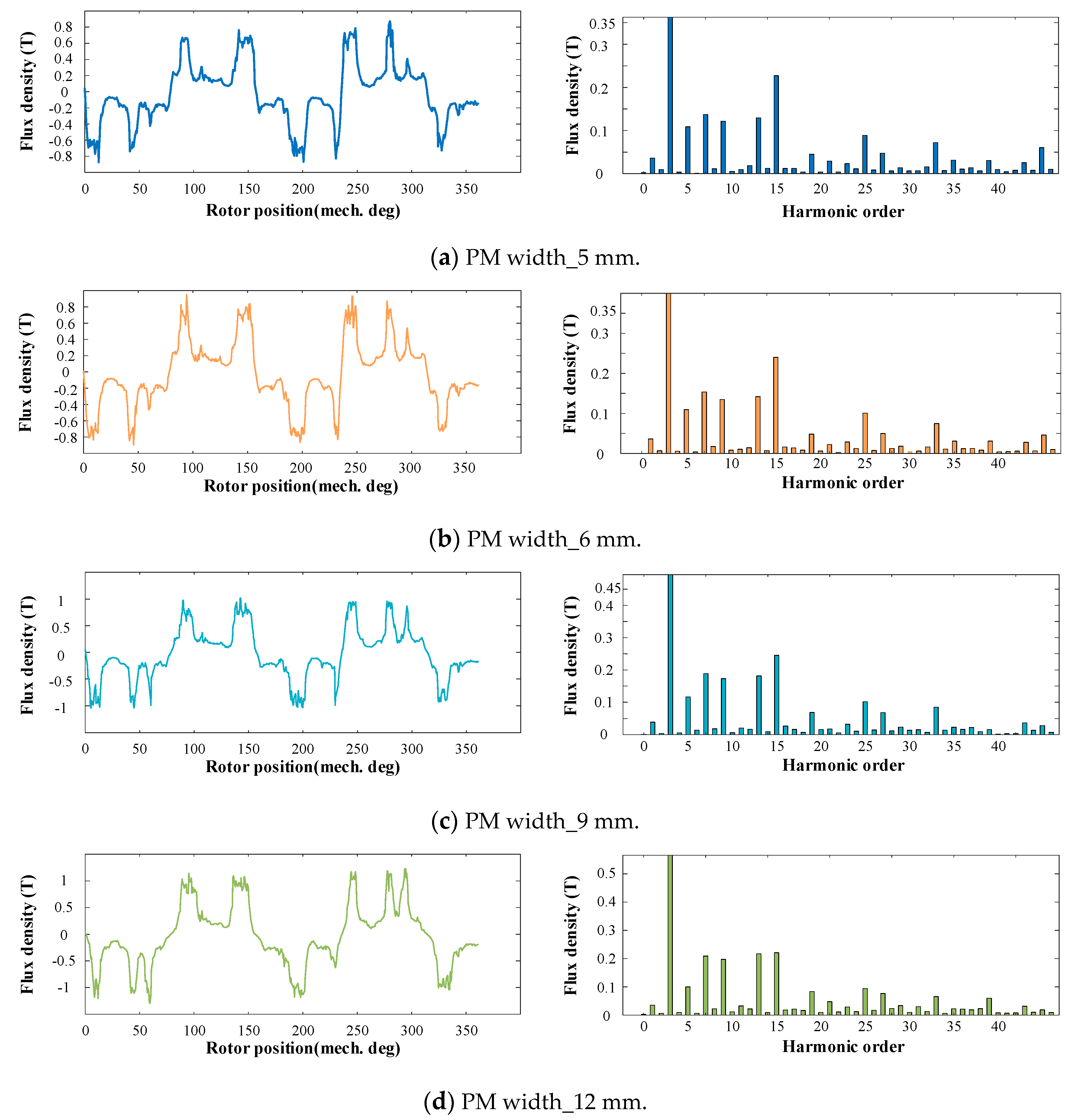
3.1.1. No-Load Flux Density

Based on the description of the air-gap flux density in Equation (8), the working harmonics of the 6/10 DSAFFSPM machine are the air-gap flux density harmonics with 1, 5, 7, 11, 13, 19, and 25 pole-pair numbers. The main working harmonic and non-working harmonic characteristics are summarized in Table 2. As shown in this table, all flux density harmonics are classified as either the stationary and rotary type. Afterwards, the corresponding speed of each harmonic is listed and the relevance between each working harmonic and both Fk and λsi is shown. The amplitude of the seventh and thirteenth (±pm + Zr) harmonics were larger than that of the fifth and twenty-fifth (5pm ± Zr) harmonics, while the first and nineteenth (±3pm + Zr) harmonics are ranked at the bottom.

3.1.2. Contributions of the Electromagnetic Torque

The torque contributions of the main-order working harmonics are illustrated in Table 3. It can be found that the analytical torque proportions of the main working harmonics on the DSAFFSPM machine are similar to the FEA results, which confirms the effectiveness of the analytical model. However, because only the main working harmonics are taken into consideration, the average torque of the analytical model is slightly lower than that of the FEA.
It can be observed in Table 1 that the high-order working harmonics (fifth (5pmZr), seventh (−pm + Zr), eleventh (7pmZr), and thirteenth (pm + Zr)) have a higher amplitude than the low-order working harmonic (first (−3pm + Zr)). However, the amplification effect of the high-order harmonics was slighter than that of the low-order harmonic, given that the high-PPN (5, 7, 11, 13), as a denominator, was much larger than the low-PPN (first). As a result, the contribution of high-order harmonics to the torque was not as large as that of the low-order harmonic.

3.2. Influence of the Parameters on the Torque Production

In the machine design, some parameters, such as the pole-arc ratio of stator-PM, the rotor ratio, and the width of the stator tooth, were of great importance for the machine performance. Among these three parameters, the pole-arc ratio of stator-PM affected the PM MMF; the rotor ratio exerted large effects on the rotor permeance; and the width of the stator tooth had a huge impact on the stator permeance. Therefore, the influence of such parameters on the torque production are investigated by means of the FEA simulation.

3.2.1. Stator-PM Pole-Arc Ratio
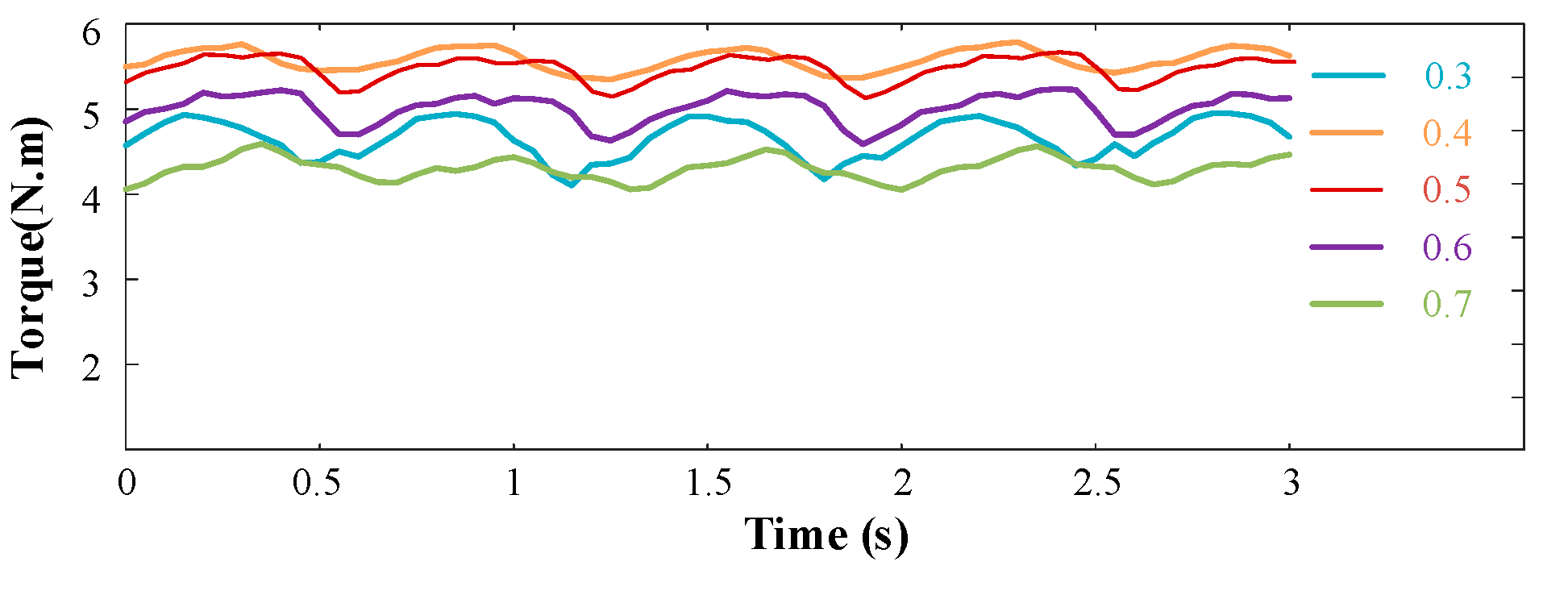
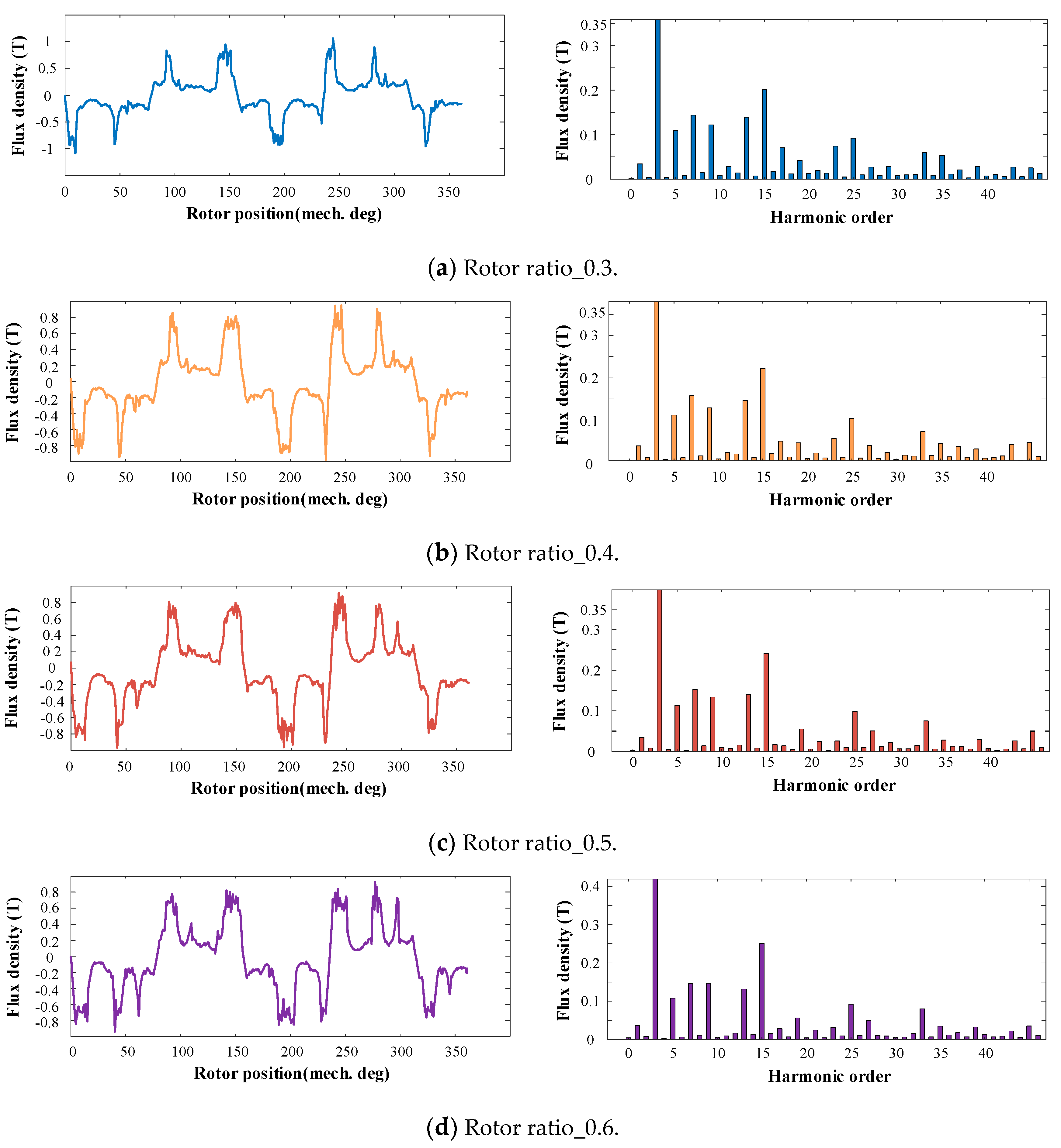
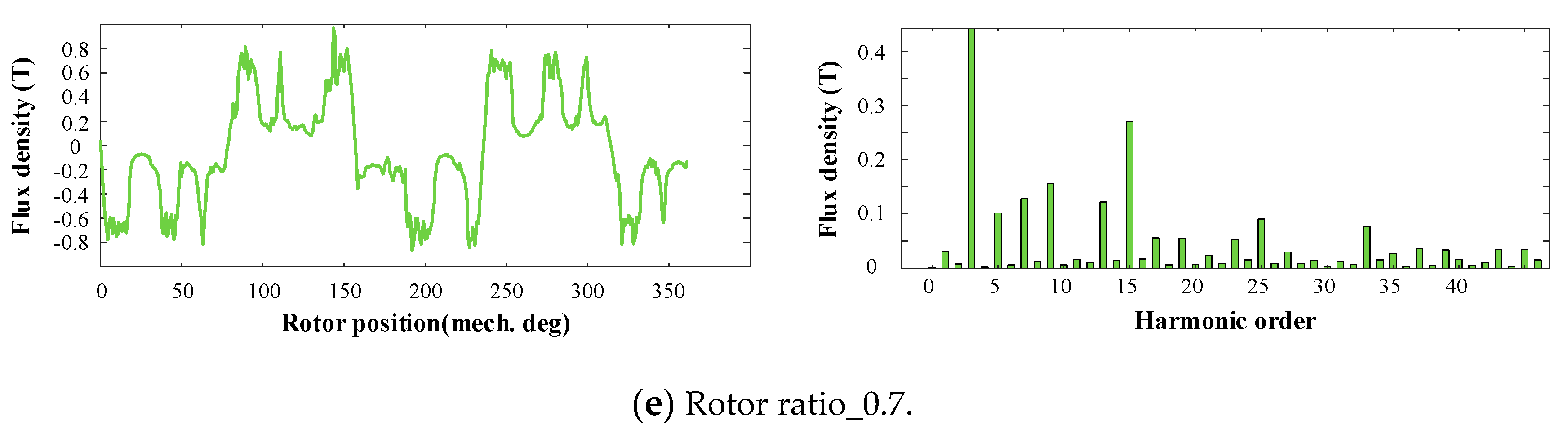
The stator-PM pole-arc ratio of the DSAFFSPM machine is defined as the ratio of PM width to the stator pole pitch
α p m = θ p m 2 π / Z s
To make a fair comparison, the stator pole pitch is set constant and the PM width varies from 5 mm to 18 mm. In Figure 3, the torque comparison is shown, which is concluded in Table 4. In Figure 4, the air-gap flux density and the corresponding spectrum are shown when the PM width is chosen as 5 mm, 6 mm, 9 mm, 12 mm, and 15 mm. The amplitude comparison of the corresponding air-gap flux density harmonics with different PM widths is presented in Table 5.
With the increase of the PM width, the torque firstly increased and then decreased, while the torque ripple showed an increasing trend and reached the peak value when the PM width was 15 mm. In Table 4, the amplitudes of the working harmonics and ipmth harmonics with varying PM widths are given. The amplitude of the low-order working harmonics, such as first and fifth, suffered minimal changes, as they were steady at the beginning and then dropped a little bit. This is mainly because the low-order magnetic field is easy to saturate with the PM width increasing and with the width of the teeth constant. It should be noted that the increasing trend of the low-order harmonic amplitude is in accordance with the trend of the torque varying with the PM width. In contrast, the high-order working harmonics, such as the seventh, eleventh, thirtieth, nineteenth, and twenty-fifth harmonics, kept increasing as the PM width increased. The rise of high-order working harmonics’ amplitudes makes little sense of the improvement of the torque. As mentioned above, the gear ratio was proportional to the torque. When the order of the air-gap flux density harmonics was high, the high number acted as the denominator, resulting in a greatly weakened amplitude of the torque. Furthermore, it can be found that the ipmth flux density harmonics were strengthened greatly with the increasing of the PM width. In particular, the third flux density harmonic reached 0.63 T at the PM width of 15 mm. However, these kinds of harmonics are non-working harmonics, which do not contribute to the torque production. Instead, these harmonics bring about large torque ripples.

3.2.2. Rotor Ratio

The rotor ratio of the DSAFFSPM machines is defined as the ratio of the circumferential angle of one rotor tooth to the rotor pole pitch
α R T = θ R T 2 π / Z r
In Figure 5, the torque comparison subjected to different rotor ratios is shown, which is concluded in Table 6. In Figure 6, the air-gap flux density and the corresponding spectrum are shown when the rotor ratio is chosen as 0.3, 0.4, 0.5, 0.6, and 0.7. The amplitudes of the corresponding air-gap flux density harmonics with different rotor ratios are presented in Table 7.
When the rotor ratio increased, the average torque firstly increased and then decreased, reaching a peak when the rotor ratio was 0.4. In contrast, the torque ripple showed a trend of falling–rising and obtained the minimum value with the rotor ratio of 0.4. When the rotor ratio augmented, the first (−3pm + Zr) and seventh (−pm + Zr) working harmonics both followed the trend of rising first and then falling. On the contrary, the trend of the eleventh (7pmZr) working harmonic was just the opposite of the first and seventh working harmonics. The trend of the torque was the same as that of the first and seventh harmonics, which resulted from the low amplitude of the eleventh harmonic and the little influence of higher harmonics on the torque. It should be noted that when the rotor was 0.7, the amplitude of each working harmonic (first, fifth, seventh, eleventh, thirteenth, twenty-fifth) was nearly the lowest of all, obviously resulting in the lowest average torque. When the rotor ratio was much higher and even the width of one rotor tooth was larger than the combination of a PM and two adjacent stator teeth, the pole flux leakage (only passing through the PM-adjacent stator teeth and one rotor tooth) was reinforced and then the main flux was reduced.

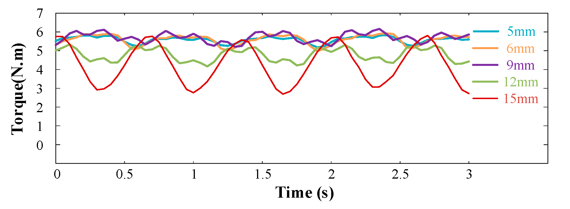
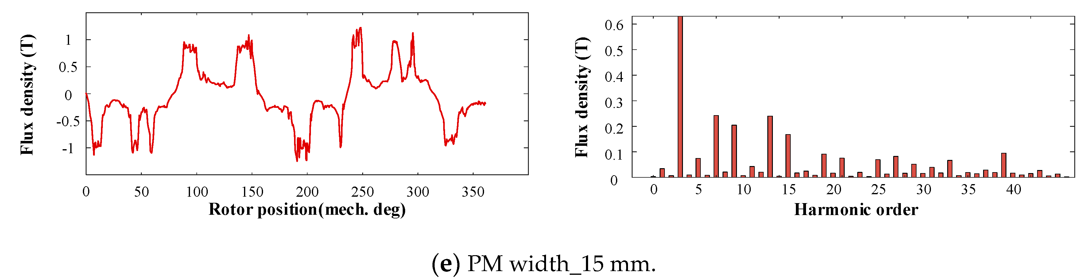
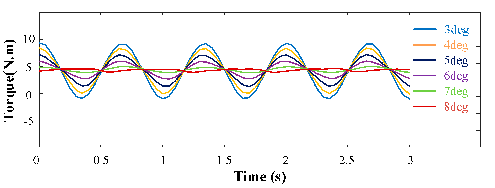
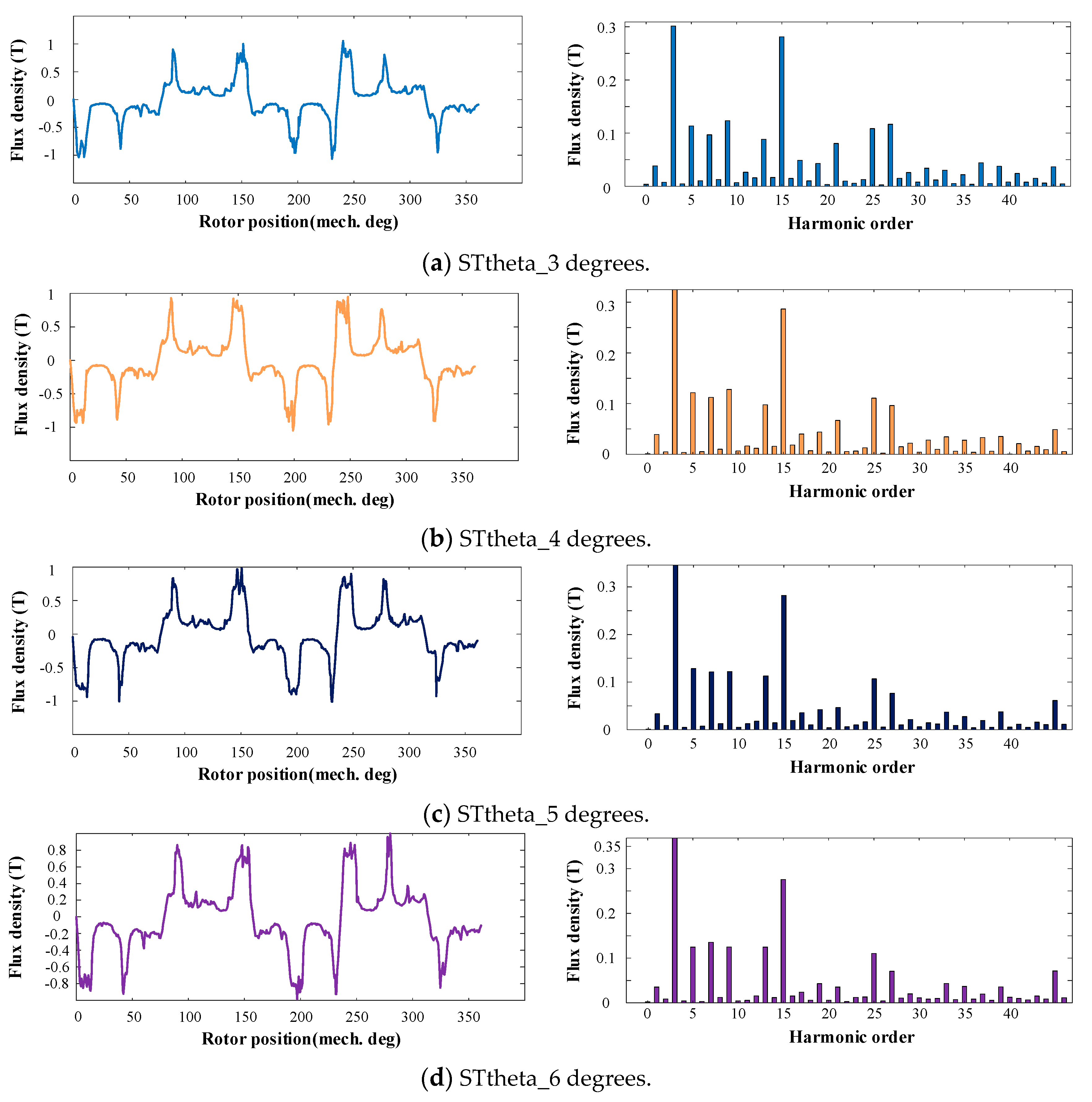
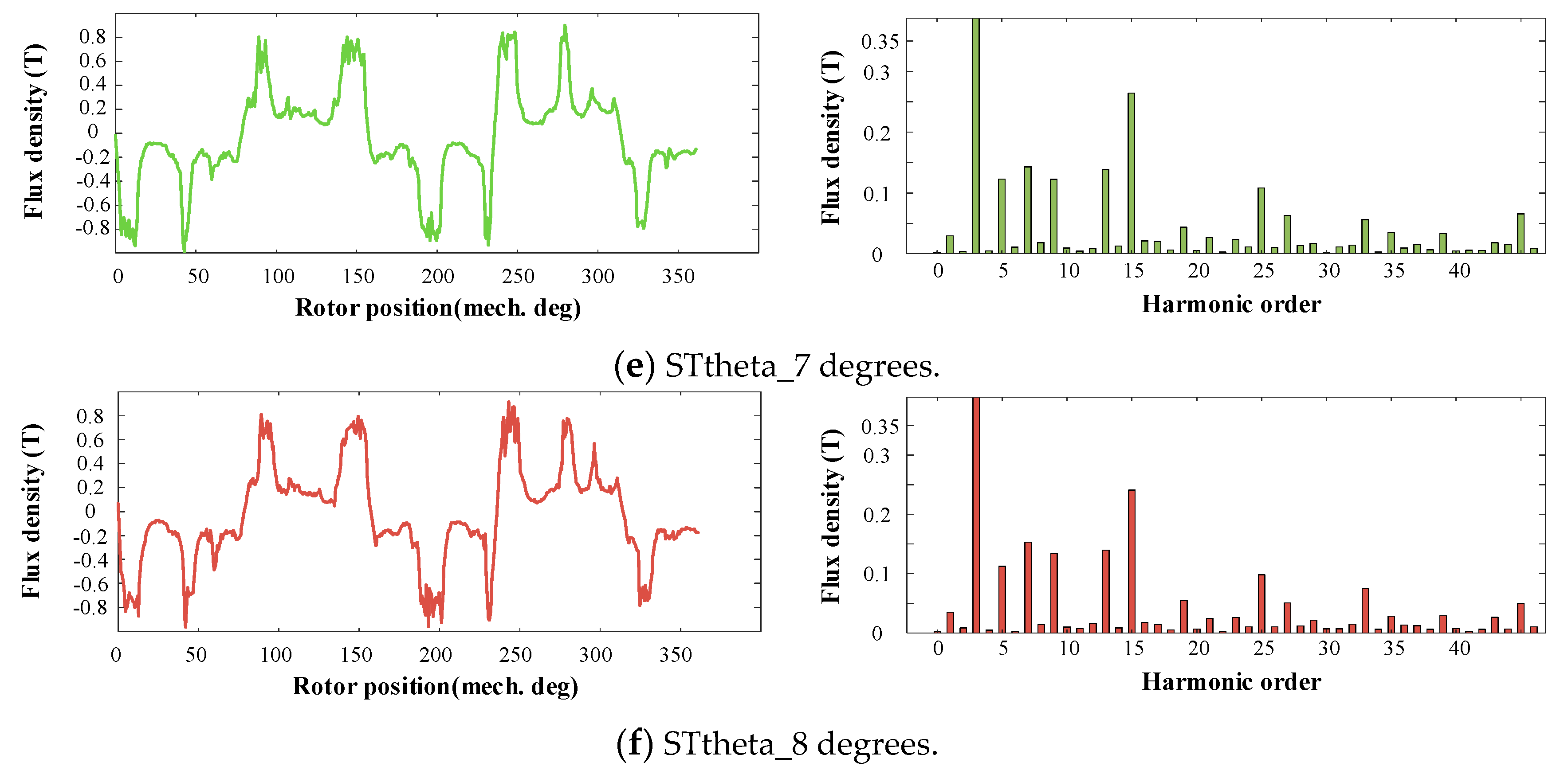
3.2.3. Width of the Stator Tooth

The stator pole pitch and the PM width remained the same, while the stator tooth width varied from 3 to 8 degrees. As the width of stator tooth increased, the slot opening decreased. Consequently, once the stator tooth width surpassed 8 degrees, enough slot space was not provided to place the windings.
Figure 7 shows the torque comparison subjected to different stator tooth widths, which is concluded in Table 8. In Figure 8, the air-gap flux density and the corresponding spectrum are shown, as the width of the stator is chosen at 3, 4, 5, 6, 7, and 8 degrees. The amplitudes of the corresponding air-gap flux density harmonics with different stator tooth widths are presented in Table 9.
When the width of the stator increased, the average torque generally showed an increasing trend. On the contrary, the torque ripple experienced a violent decrease. In particular, the trend of the torque ripple was the same as that of the PM width. This was because the cogging torque changed greatly when these two parameters changed. In addition, the seventh (pmZr) and thirteenth (pm + Zr) harmonics were more affected by the stator slot width. When the width of the stator teeth was small, the magnetic fields of both the high-order and low-order harmonics were saturated. As the tooth width gradually increased, the low-order magnetic field no longer changed and remained saturated considering the E-core stator configuration provided an auxiliary path for the low-order magnetic harmonics. However, given that the wide teeth can allow for a more high-order magnetic flux to pass, the high-order magnetic field was less affected by the saturated tooth part; thus, more high-order magnetic field flux lines passed through the tooth part to form the main magnetic field. Benefiting from the more high-order magnetic field path, the amplitude high-order of the air-gap density increased.
To conclude, the torque firstly increased and then decreased with the increase of the PM width, and the change of the PM width was related to the fifth, seventh, eleventh, and thirteenth harmonics. In addition, the average torque experienced a falling–rising trend when the rotor ratio increases, reaching a peak when the rotor ratio was 0.4. The change of the rotor ratio was related to the first, seventh, and eleventh harmonics. Moreover, as the width of the stator increased, the average torque generally showed an increasing trend. The change of the stator teeth was related to the seventh and thirteenth harmonics. Considering the E-core stator is utilized in the prototype, the low-order magnetic harmonics provided an auxiliary path to pass through. Therefore, the change of the PM width and the stator tooth nearly had no influence on the first harmonic. In particular, when the rotor ratio was chosen as 0.4, the amplitude of the first and seventh harmonics was the highest, resulting in the largest torque.

3.2.4. Torque Characteristics after Optimization

The optimized parameters including the PM width, rotor ratio, and stator tooth width were chosen as 6 mm, 0.4, and 8 degrees, respectively. The comparison of the torque contributions of the main-order working harmonics before and after the optimization was made and is listed in Table 10. After the optimization, the average torque was increased by 9.4% and most of the torque improvement was constituted by the low-order working harmonics.

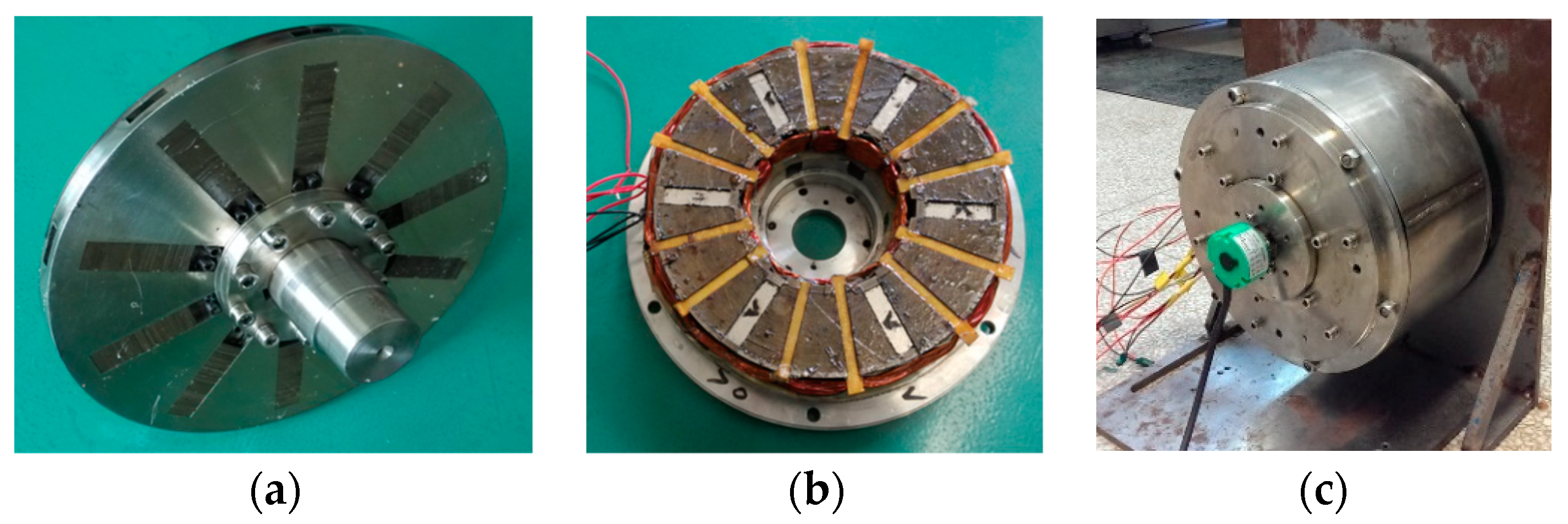
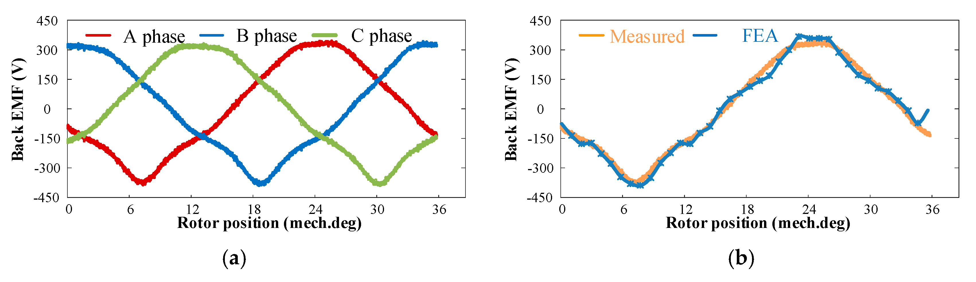
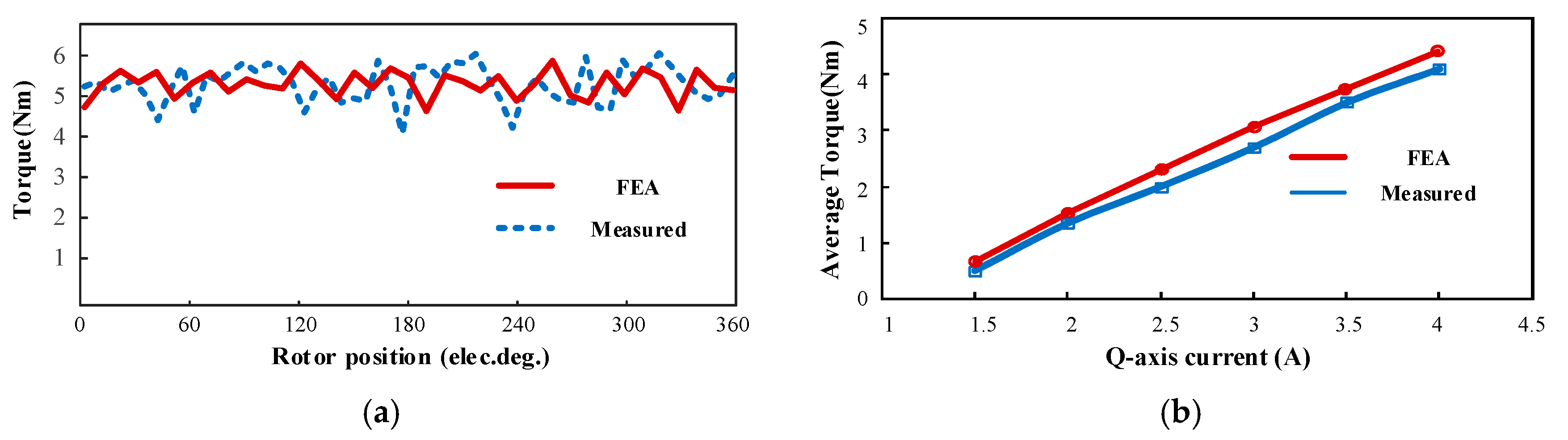
3.3. Experimental Verification

To verify the above theoretical analysis, a 6/10 E-core DSAFFSOM machine was manufactured. Figure 9 sketches the stator, rotor, and the whole machine. Figure 10 and Figure 11 display the FEA-predicted and both the measured back-EMF and electro-magnetic torque, and the machine operated at rated speed (3000 r/min). The waveform of the measured back-EMF is slightly lower than that of the predicted one, which is mainly because of the ignorance of the end effect and some mechanical losses. Furthermore, the measured torque ripple is a little bit higher than the FEA-predicted results because of some machining errors in the manufacturing process.
The waveform of the measured and FEA-predicted output torque versus the armature current is shown in Figure 11b. The measured torque is slightly lower than the FEA-predicted results due to mechanical loss and manufacturing errors. When the motor speed was rated and the d-axis current was zero, the output torque increased almost linearly with the increase of the armature current, which means that under the condition of the light load, the armature current of the motor can meet the demand of torque output. Nonetheless, the air-gap no-load flux density and the corresponding working harmonics of the prototyped machine cannot be measured directly.
In general, the difference between the measured value and the predicted value is very small, which also validates the above theoretical and finite element simulation analysis.

4. Conclusions

In this paper, an in-depth investigation of the torque production mechanism of the DSAFFSPM machine is carried out. The MMF-permeance model is employed to identify the main-order working harmonics for the torque generation. From the theoretical analysis and FEA results, the detailed findings can be summarized as follows.
(1)
The torque of the DSAFFSPM machine is consituted by the modulated field harmonics ( k p m ± j Z r th) and the fundamental PM filed harmonics ( k p m th) cannot the generate steady torque.
(2)
The torque is mainly constituted by the low-order working harmonics, which confirms the field modulation effect in the DSAFFSPM machines.
(3)
Each order of PM MMF, each order of the stator permeance, and only the 0th rotor permeance components are responsible for the torque production of the DSAFFSPM machines.
(4)
The change of the PM width and stator tooth have nearly no influence on the first harmonic. In particular, when the rotor ratio is chosen as 0.4, the amplitude of the first and seventh harmonics is the highest, resulting in the largest torque.
In conclusion, the experimental results on a manufactured 6/10 E-core DSAFFSPM machine validate the theoretical and FEA results.

Author Contributions

Conceptualization, S.W., Y.K. and M.L.; methodology, S.W.; software, S.W.; validation, S.W.; formal analysis, S.W.; investigation, S.W.; resources, M.L.; data curation, S.W.; writing—original draft preparation, S.W.; writing—review and editing, S.W. and K.L.; visualization, S.W. and M.L.; supervision, K.L.; project administration, M.L.; funding acquisition, M.L. All authors have read and agreed to the published version of the manuscript.

Funding

This research was funded by China NCFC under Grant 51937002.

Institutional Review Board Statement

Not applicable.

Informed Consent Statement

Not applicable.

Data Availability Statement

Not applicable.

Conflicts of Interest

The authors declare no conflict of interest.

References

  1. Zhu, Z.Q.; Khatab, M.F.; Li, H.; Liu, Y. A novel axial flux magnetically geared machine for power split application. IEEE Trans. Ind. Appl. 2018, 54, 5954–5966. [Google Scholar] [CrossRef]
  2. Bai, J.; Zheng, P.; Tong, C.; Song, Z.; Zhao, Q. Characteristic analysis and verification of the magnetic-field-modulated brushless double-rotor machine. IEEE Trans. Ind. Electron. 2014, 62, 4023–4033. [Google Scholar] [CrossRef]
  3. Ji, W.; Ni, F.; Gao, D.; Luo, S.; Lv, Q.; Lv, D. Electromagnetic Design of high-power and high-speed permanent magnet synchronous motor considering loss characteristics. Energies 2021, 14, 3622. [Google Scholar] [CrossRef]
  4. Zhu, X.; Ji, J.; Xu, L.; Kang, M. Design and analysis of dual-stator PM vernier linear machine with PMs surface-mounted on the mover. IEEE Trans. Appl. Supercond. 2018, 28, 5201605. [Google Scholar] [CrossRef]
  5. Su, P.; Hua, W.; Wu, Z.; Han, P.; Cheng, M. Analysis of the operation principle for rotor-permanent-magnet flux-switching machines. IEEE Trans. Ind. Electron. 2018, 65, 1062–1073. [Google Scholar] [CrossRef]
  6. Hua, H.; Hua, W.; Zhao, G.; Cheng, M. Torque production mechanism of switched reluctance machines with air-gap field modulation principle. IEEE Trans. Energy Convers. 2020, 35, 1617–1627. [Google Scholar] [CrossRef]
  7. Zhu, X.; Hua, W.; Zhao, G. Analysis of open-circuit performances in flux-reversal permanent magnet machines by superposition methods. IEEE Trans. Energy Convers. 2021. Available online: https://ieeexplore.ieee.org/document/9410385 (accessed on 21 April 2021). [CrossRef]
  8. Hua, W.; Cheng, M.; Zhu, Z.Q.; Howe, D. Analysis and optimization of back-EMF waveform of a flux switching PM motor. IEEE Trans. Energy Convers. 2008, 23, 727–733. [Google Scholar] [CrossRef]
  9. Cheng, M.; Hua, W.; Zhang, J.; Zhao, W. Overview of stator permanent magnet brushless machines. IEEE Trans. Ind. Electron. 2011, 58, 5087–5101. [Google Scholar] [CrossRef]
  10. Li, D.; Qu, R.; Li, J.; Xu, W.; Wu, L. Synthesis of flux switching permanent magnet machines. IEEE Trans. Energy Convers. 2016, 31, 106–117. [Google Scholar] [CrossRef]
  11. Chen, J.T.; Zhu, Z.Q.; Iwasaki, S. A novel E-core switched-flux PM brushless ac machine. IEEE Trans. Ind. Appl. 2011, 47, 1273–1282. [Google Scholar] [CrossRef]
  12. Zhou, R.; Li, G.; Zhan, K. Performance investigation of consequent-pole PM machines with E-core and C-core modular stators. IEEE Trans. Energy Convers. 2021, 36, 1169–1179. [Google Scholar] [CrossRef]
  13. Li, Y.; Yang, H.; Lin, H.; Lyu, S.; Pan, Z. Comparative study of stator-consequent-pole permanent magnet machines with different stator-slot configurations. IEEE Trans. Magn. 2019, 55, 8106308. [Google Scholar] [CrossRef]
  14. Yang, H.; Li, Y.; Lin, H.; Zhu, Z.Q.; Lyu, S. Principle investigation and performance comparison of consequent-pole switched flux PM machines. IEEE Trans. Transport. Electrific. 2021, 7, 766–778. [Google Scholar] [CrossRef]
  15. Jia, L.; Lin, K.; Lin, M.; Le, W.; Wang, S. Comparative analysis of dual-rotor modular stator axial-flux permanent magnet machines with different rotor topologies. IEEE Trans. Appl. Supercond. 2021, 31, 5204405. [Google Scholar] [CrossRef]
  16. Zhao, J.; Quan, X.; Sun, X.; Li, J.; Lin, M. Design of a novel axial flux rotor consequent-pole permanent magnet machine. IEEE Trans. Appl. Supercond. 2020, 30, 5205506. [Google Scholar] [CrossRef]
  17. Jia, L.; Lin, M.; Le, W.; Li, N.; Kong, Y. Dual-skew magnet for cogging torque minimization of axial flux PMSM with segmented stator. IEEE Trans. Magn. 2020, 56, 7507306. [Google Scholar] [CrossRef]
  18. Li, N.; Zhu, J.; Lin, M.; Yang, G.; Kong, Y.; Hao, L. Analysis of axial field flux-switching memory machine based on 3-d magnetic equivalent circuit network considering magnetic hysteresis. IEEE Trans. Magn. 2019, 55, 7203104. [Google Scholar] [CrossRef]
  19. Xu, D.; Lin, M.; Fu, X.; Hao, L.; Zhang, W.; Li, N. Cogging torque reduction of a hybrid axial field flux-switching permanent-magnet machine with three methods. IEEE Trans. Appl. Supercond. 2016, 26, 5201305. [Google Scholar] [CrossRef]
  20. Zhang, W.; Liang, X.; Lin, M.; Hao, L.; Li, N. Design and analysis of novel hybrid-excited axial field flux-switching permanent magnet machines. IEEE Trans. Appl. Supercond. 2016, 26, 5201005. [Google Scholar] [CrossRef]
  21. Zhang, W.; Liang, X.; Lin, M. Analysis and comparison of axial field flux-switching permanent magnet machines with three different stator cores. IEEE Trans. Appl. Supercond. 2016, 26, 0607806. [Google Scholar] [CrossRef]
  22. Wang, S.; Lin, K.; Lin, M. Comparative study of E- and U-core modular dual-stator axial-field flux-switching permanent magnet motors with different stator/rotor-pole combinations based on flux modulation principle. IEEE Access 2021, 9, 78635–78647. [Google Scholar] [CrossRef]
  23. Gaussens, B.; De la Barrière, O.; Hoang, E.; Saint-Michel, J.; Manfe, P.; Lécrivain, M.; Gabsi, M. Magnetic field solution in doubly slotted airgap of conventional and alternate field-excited switched-flux topologies. IEEE Trans. Magn. 2013, 49, 5083–5096. [Google Scholar] [CrossRef]
  24. Heller, B.; Hamata, V. Harmonic Field Effects in Induction Machines; Elsevier: Amsterdam, The Netherlands, 1977. [Google Scholar]
Figure 1. Configuration of DSAFFSPM machine.
Energies 14 05498 g001
Figure 2. The stator and the rotor diagram and their corresponding air-gap permeance and PM MMF.
Energies 14 05498 g002
Figure 3. Electromagnetic torque subjected to different PM widths.
Energies 14 05498 g003
Figure 4. The air-gap flux density and the corresponding spectrum with various PM widths: (a) PM width_5 mm; (b) PM width_6 mm; (c) PM width_9 mm; (d) PM width_12 mm; and (e) PM width_15 mm.
Energies 14 05498 g004aEnergies 14 05498 g004b
Figure 5. Electromagnetic torque subjected to different rotor ratios.
Energies 14 05498 g005
Figure 6. The air-gap flux density and the corresponding spectrum with various rotor ratios: (a) rotor ratio_0.3; (b) rotor ratio_0.4; (c) rotor ratio_0.5; (d) rotor ratio_0.6; and (e) rotor ratio_0.7.
Energies 14 05498 g006aEnergies 14 05498 g006b
Figure 7. Electromagnetic torque subjected to different stator tooth widths.
Energies 14 05498 g007
Figure 8. The airgap flux density and the corresponding spectrum with various stator tooth widths: (a) STtheta_3 degrees; (b) STtheta_4 degrees; (c) STtheta_5 degrees; (d) STtheta_6 degrees; (e) STtheta_7 degrees; and (f) STtheta_8 degrees.
Energies 14 05498 g008aEnergies 14 05498 g008b
Figure 9. Prototype of the 6/10 E-core DSAFFSPM machine: (a) 10-pole rotor; (b) stator with 6 E-core modules; and (c) prototype machine.
Energies 14 05498 g009
Figure 10. Comparison of the measured and FEA-predicted back-EMF waveforms of the DSAFFSPM machine. (a) The measured waveforms. (b) Both the measured and FEA-predicted waveforms.
Energies 14 05498 g010
Figure 11. Comparison of the measured and FEA-predicted torque waveforms of the DSAFFSPM machine. (a) Torque at rated speed and rated current. (b) Average torque versus currents.
Energies 14 05498 g011
Table 1. Parameters of the 6/10 E-core DSAFFSPM machine.
Item and SymbolValueItem and SymbolValue
Phase, m3Inside stator diameter, Dsi (mm)110.2
Number of stator teeth, Zs6Rotor axial length, lr (mm)14
Pole number of stator-PMs, pm3Stator axial length, ls (mm)25.5
Number of rotor salient poles, Zr10Air-gap length, ga (mm)1
Pole number of armature windings, pa7PM width, hpm (mm)6
Outside stator diameter, Dso (mm)198.4
Table 2. Characteristics of no-load air-gap flux density harmonics.
Harmonic TypeHarmonic Pole-PairsFk, λrj, and λsi6/10 E-CoreSpeed
Stationarykpmpm,
3pm
5pm
……..3, 9, 15,…0
(k± 2i)pm0
Rotatingkpm±Zr
&
(k± 2i)pmZr
pm + ZrF1, λr1, λs0,
F1, λr1, λs1,
F3, λr1, λs1,
13ZrΩ/pm + Zr
−pm + Zr7ZrΩ/Zrpm
3pm + ZrF1, λr1, λs1,
F3, λr1, λs0,
F3, λr1, λs3,
1ZrΩ/3pmZr
3pm + Zr19ZrΩ /3pm + Zr
5pm − ZrF1, λr1, λs3,
F3, λr1, λs1,
5ZrΩ/5pmZr
5pm + Zr25ZrΩ /5pm + Zr
7pm − ZrF1, λr1, λs3,11ZrΩ/7pmZr
Table 3. Torque contributions of the main-order working harmonics.
ItemAmplitudes of the Harmonics (T)Average Torque (Nm)Torque Proportion (%)
−3pm + Zr, 1st0.031.5932.7
5pmZr, 5th0.101.0621.8
pm + Zr, 7th0.141.0621.8
7pmZr, 11th0.030.142.9
pm + Zr, 13th0.140.5611.7
3pm + Zr, 19th0.080.224.6
5pm + Zr, 25th0.100.214.4
sum 4.84(analytical)/4.98(FEA)99.9
Table 4. Torque comparison with different PM widths.
PM Width (mm)5 mm6 mm9 mm12 mm15 mm
Torque average (N.m)5.435.485.654.703.59
Torque ripple (%)5.676.378.2328.2379.70
Table 5. Air-gap flux density harmonics comparison with different PM widths.
Harmonic Order157111319253915
5 mm0.040.110.140.010.130.040.090.360.120.23
6 mm0.040.110.150.010.140.050.100.400.130.24
9 mm0.040.120.170.020.180.070.100.500.170.25
12 mm0.030.10.210.030.220.080.090.570.200.22
15 mm0.030.080.240.040.240.090.070.630.200.17
Table 6. Torque comparison with different rotor ratios.
Rotor Ratio0.30.40.50.60.7
Torque average (N.m)4.715.745.524.904.33
Torque ripple (%)12.155.856.177.456.70
Table 7. Air-gap flux density harmonics comparison with different rotor ratios.
Harmonic Order157111319253915
0.30.030.110.140.030.140.040.090.360.120.20
0.40.040.110.160.020.140.040.100.380.130.22
0.50.040.110.150.010.140.050.100.400.130.24
0.60.040.110.150.010.130.060.090.420.150.25
0.70.030.100.130.020.120.050.090.440.160.27
Table 8. Comparison of torques with different stator tooth widths.
Stator Tooth Width3 deg.4 deg.5 deg.6 deg.7 deg.8 deg.
Torque average (N.m)4.544.885.095.395.565.46
Torque ripple (%)198.85145.5185.7150.89.725.64
Table 9. Air-gap flux density harmonics comparison with different stator tooth widths.
Harmonic Order157111319253915
3 degrees0.040.110.100.030.090.040.110.300.120.28
4 degrees0.040.120.110.020.100.040.110.320.130.29
5 degrees0.040.120.120.010.110.040.110.350.120.28
6 degrees0.040.120.140.010.120.040.110.370.120.28
7 degrees0.040.120.140.000.140.040.110.390.120.26
8 degrees0.030.110.150.010.140.050.100.400.130.24
Table 10. Comparison of the torque contributions of the main-order working harmonics before and after the optimization.
ItemAmplitudes of the Harmonics
(before/after) T
Average Torque
(before/after) Nm
Torque Proportion
(before/after) %
−3pm + Zr, 1st0.03/0.041.63/2.1332.7/39.1
5pmZr, 5th0.10/0.111.09/1.1821.8/21.6
pm + Zr, 7th0.14/0.151.09/1.1521.8/21.1
7pmZr, 11th0.03/0.010.14/0.052.9/0.89
pm + Zr, 13th0.14/0.140.58/0.5811.7/10.6
3pm + Zr, 19th0.08/0.050.23/0.144.6/2.6
5pm + Zr, 25th0.10/0.100.22/0.214.4/3.9
sum 4.98/5.4599.9/99.79
Publisher’s Note: MDPI stays neutral with regard to jurisdictional claims in published maps and institutional affiliations.

