Article

Design and Characteristic Analysis of a Homopolar Synchronous Machine Using a NI HTS Field Coil

Division of Electronics and Electrical Information Engineering, College of Ocean Science and Engineering, Korea Maritime & Ocean University, Busan 49112, Korea
Energies 2021, 14(18), 5658; https://doi.org/10.3390/en14185658
Submission received: 6 August 2021 / Revised: 2 September 2021 / Accepted: 6 September 2021 / Published: 8 September 2021
(This article belongs to the Special Issue Future Electrical Machines)

Abstract

:
This paper deals with a homopolar synchronous machine (HSM) applying high-temperature superconducting (HTS) field coils. Superconductors, especially high-temperature superconductors, have high potential as advanced materials for next-generation electrical machines due to their high critical current density and excellent mechanical strength. However, coils made with high-temperature superconductors have a high risk of being damaged in the event of a quench due to the intrinsic low normal zone propagation velocity (NZPV). Therefore, the coil protection issue has been regarded as one of the most important research fields in HTS coil applications. Currently, the most actively studied method for quench protection of the HTS coils is the no-insulation (NI) winding technique. The NI winding technique is a method of winding an HTS coil without inserting an insulating material between turns. This method can automatically bypass the current to the adjacent turn when a local quench occurs inside the HTS coil, greatly improving the operating stability of the HTS coils. Accordingly, many institutions are conducting research to develop advanced electrical machines using NI HTS coils. However, the NI HTS coil has its intrinsic charge/discharge delay problem, which makes it difficult to successfully develop electrical machines using the NI HTS coil. In this study, we investigated how this charging/discharging problem appeared when the NI HTS coil was used in an HTS homopolar synchronous machine (HSM) which is one of the electrical machines with a high possibility of applying the HTS coil in the future because it has a stationary field coil structure. For this, the characteristic resistances of HTS coils were experimentally obtained and applied to the simulation model.

1. Introduction

High-temperature superconducting (HTS) wires have excellent critical current and mechanical properties, making them suitable materials for high magnetic field applications. Thus, many studies are being carried out to apply high magnetic field coils made of HTS wires to electrical machines such as motors and generators as well as analytical equipment such as NMR and MRI [1,2]. Among them, motors and generators to which HTS coils are applied can have high output power density, so they are considered as one of the promising future electrical machines. Accordingly, many studies have been conducted to develop various types of HTS generators and HTS motors for each application field. Several research groups have conducted research on applying HTS field coils to transverse flux type generators, air-core type generators, and flux switching type generators for wind power generation [3,4,5]. Additionally, other research groups have conducted research on HTS motors for application to electric vehicles such as electric ships [6,7,8]. In addition, the HTS homopolar machine has been studied for an aircraft application because it is suitable for high-speed operation [9]. In general, HTS coils are used as field windings in HTS motors and generators, and among them, they are being studied as field windings of synchronous machines due to the characteristics of superconductors that cause AC loss in time-varying currents [10,11,12]. The most common HTS-synchronous machine is a type in which HTS field coils are installed on a non-magnetic rotor core. This HTS-synchronous machine has a structure in which the HTS field coils rotate to generate an alternating magnetic field in an air-gap. In this HTS-synchronous machine, the structures of the cooling system and the excitation system for HTS field coils become complicated because the superconducting coil is excited with a very high current under cryogenic cooling conditions of several tens of Kelvin or less. In addition, in the HTS-synchronous machines with a rotating field coil structure, the HTS coils require a structure and material to support them from rotational motion, and epoxy impregnation of the HTS coil is one of them [13,14]. Therefore, the conventional HTS-synchronous machines are mainly studied in the application field, requiring high output at a relatively low rotating speed. Such an HTS-synchronous machine requires technology for stably operating HTS coils as in other HTS machines. Therefore, it is difficult to apply the conventional HTS-synchronous machine which has a rotational field winding structure in an application field that must be operated at a high rotation speed. For this reason, studies on novel electrical rotating machines in which the HTS field coils are applied to electrical rotating machines such as flux-switching type, homopolar type, and vernier type is being conducted. Since these HTS electrical rotating machines have a stationary HTS field winding structure [4,5,6,7,8], the structures of the cooling system and the excitation system for the HTS field coil can be greatly simplified compared to the conventional HTS electrical rotating machine. In addition, the stationary HTS field coil structure enables very stable operation at high rotating speeds [15,16]. Additionally, another advantage is that since the HTS field coil is not moved together by the rotation of the rotor core, the mechanical support structure can be simplified, and it can be free from epoxy impregnation of the HTS field coil. This makes it possible to apply the no-insulation winding method, which can dramatically improve the stability of the HTS field coil [17,18,19,20,21,22]. NI winding is one of the most actively researched methods as a protection technology for HTS coils. The NI winding method is to wind without inserting an insulation material between turns when manufacturing an HTS coil. Even in this way, since the electrical resistance of the superconducting layer is virtually zero, the time-invariant component of the coil current flows only to the superconducting layer in the HTS wire. Therefore, in the steady-state condition in which the HTS coil is totally excited, the normal operation of the machine is possible. However, if a quench occurs in the HTS coil and a hot spot occurs in the local region of the HTS coil, the coil current can bypass the region adjacent to the hot spot. Since this process is performed passively without any detection of quench occurrence, the stability of the HTS coil can be dramatically improved. Although a simple principle, this method has been greatly encouraging to many superconducting magnet engineers because the HTS is very slow for normal zone propagation velocity (NZPV) compared to the low-temperature superconductor (LTS). However, despite these advantages of the NI HTS coil, there are problems to be solved for the practical development of electrical machines applying NI HTS coils. These problems are mainly due to the charging/discharging delay phenomenon, which is caused by partial leakage of the coil current in the direction of the turn-to-turn contact due to the reactance by the coil inductance in the charging/discharging period. Therefore, in order to develop electrical machines using the NI HTS coil, it is necessary to analyze and improve such a charging/discharging delay phenomenon. In this paper, the operating characteristics when the NI HTS field coil is applied to a homopolar synchronous machine (HSM), which is one of the electrical rotating machines with a stationary field winding, are analyzed. The HSM was selected as the prototype model because it is advantageous to apply an NI coil without epoxy impregnation due to its stationary HTS field coil structure. Unlike other HTS rotating machines, since the HTS field coil is fixed, the mechanical stability is high, and the excitation and cooling structure of the HTS coil can be simplified. The mechanical stability of the fixed-operated NI HTS coil has already been confirmed through a long-term operation test of the NI HTS magnet for NMR [2].
Additionally, the effectiveness of the partial-insulation (PI) winding method proposed to improve the charging/discharging delay of the NI HTS coil is analyzed by finite element analysis linked with electrical circuit simulation based on the designed HTS HSM model. In order to make an accurate simulation model, the characteristic resistances according to the winding method are experimentally derived by testing small-scale HTS coils. Additionally, by applying these to the simulation model, the operating characteristics of the HTS HSM according to the winding method of the HTS field coil are analyzed.

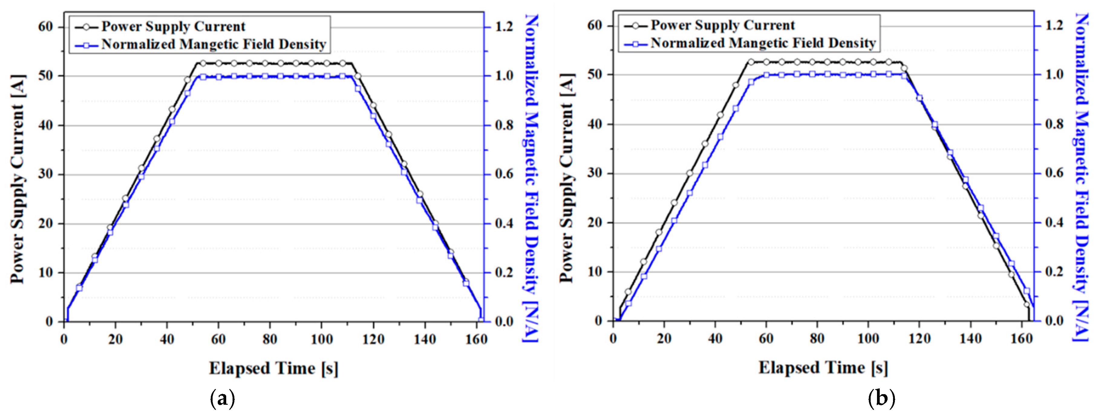
2. Characteristic Resistances of the HTS Coils According to the Winding Method

For the modeling of an HTS HSM using NI HTS field coils, charging/discharging tests of HTS coils were performed. The specifications and pictures of the HTS coils used for these tests are shown in Table 1 and Figure 1 [23]. The HTS coils are wound with 2G HTS wire, and are divided into four types of coils according to the insulation method between winding turns. The self-field critical current of the 2G HTS wire at 77 K is about 109 A. Coil I is an HTS coil with a conventional insulation structure in which the insulating tape is inserted between each winding turn. On the other hand, Coil II is a no-insulation coil without an insulating material inserted between all winding turns. Coil III and Coil IV are partial-insulation (PI) coils in which the insulating tape is inserted once per specific intervals of winding turns. The insulating tape is inserted once every eight turns for Coil III and once every four turns for Coil IV. All coils have the same specifications, such as inner diameter, winding turns, and critical current, except for the insulation structure. The picture on the left in Figure 1 shows the experimental setup for the charging/discharging tests. The current of the HTS coil was charged and discharged using a magnet power supply, and a cryogenic hall sensor was installed in the center of the HTS coil to measure the magnetic field generated in the HTS coil. The HTS coil was cooled with liquid nitrogen, and the power supply current and magnetic field signals were recorded in a PC through a DAQ device. Figure 2 shows the simplified equivalent circuit models of the insulation coil, no-insulation coil, and partial-insulation coil. This is a lumped circuit model that can explain the charging/ discharging delay mechanism of no-insulation coils [24,25]. In these models, LHTS represents the inductance of the HTS coil, and RC and Rθ represent the characteristic resistance in the contact direction between turns and the resistance in the winding direction, respectively. Rθ is almost zero in the normal state but increases in magnitude when a normal zone occurs in the HTS coil. Under the condition of DC current or current with a very small rate of change with time, almost all current flows only in the winding direction along the HTS layer because the impedance due to the LHTS is almost zero. Therefore, in a state where the current is fully excited, the no-insulation HTS coil generates a magnetic field similar to the insulated HTS coil. On the other hand, in the charging/ discharging sequence, the current is distributed according to the ratio of RC and impedance by LHTS. Additionally, this causes a delay phenomenon between the power supply current and the magnetic field generated by the HTS coil because of the leakage current to RC. Therefore, in order to improve the charging/discharging delay problem of the NI HTS coil, RC should be increased. For this purpose, methods such as coating a metal having a relatively high electrical resistance on the HTS wire or winding a tape made of such a metal together with the HTS wire have been proposed. In this study, in order to increase the RC, the HTS coil was insulated by inserting Kapton tape at regular intervals of winding turns. This method can be represented as an equivalent circuit as shown in Figure 2c because the winding turns except for the insulation layer are wound without insulation from each other. Therefore, while increasing the overall RC, it is possible to maintain the self-protection characteristics of the no-insulation coil.
Figure 3 shows the charging/discharging test results for these HTS coils. The HTS coils were charged up to 52 A, which is about 70% of the coil’s critical current, and after reaching the target current, the current was maintained for about 1 min and then discharged. In the charging/discharging sequence, the ramping up/down speed of the power supply current was set to 1 A/s, and the change in the magnetic field was measured using a hall sensor installed in the center of the coil. Figure 3a shows the test result of the insulated HTS coil, where the power supply current and magnetic field match relatively accurately during the charging and discharging. On the other hand, the test results of the no-insulation coil in Figure 3b do not match the graphs of the power supply current and the magnetic field, especially in the discharging sequence. This is due to the leakage current in the contact direction between winding turns, which causes the slope of the magnetic field graph in the charging/discharging sequence to be smaller than that of the insulated HTS coil. Additionally, the effect of partial insulation can be examined through Figure 3c,d. Figure 3c is a test result in an HTS coil with an insulating tape inserted once every eight turns, and it shows that the slope of the graph of the magnetic field in the charging/discharging sequence is increased compared to that in the no-insulation. Figure 3d is the test result for the HTS coil in which the insulating tape is inserted once every four turns, and the charging/discharging delay problem is further improved. These experimental results show that as the number of insulating layers increases, the charging/discharging delay problem is improved. However, although it is not within the scope of this study, this method weakens the self-protection properties, so it is necessary to study to find suitable conditions for the application.
Figure 4 shows the results of the sudden discharging test performed to determine the characteristic resistance in the contact direction between winding turns according to the insulation structure [26,27]. As shown in Figure 4a, in Coil I, the magnetic field drops to zero at the same time as the power supply current is discharged. In the other coils, the power supply current dropped rapidly from 52 A to 0 A, and after the power supply current is completely discharged, the time interval until the magnetic field drops to 36.8% was measured. The time constants of Coil II, Coil III, and Coil IV were 4.184, 3.572, and 1.504 s, respectively. These results show that the charging/discharging delay time of the no-insulation coil can be improved by about 2.8 times by using the partial-insulation method. In the lumped circuit model of the no-insulation coil, since the coil inductance and the equivalent characteristic resistance are parallel-connected, the time constant can be calculated using τ = L H T S / R C . Therefore, the equivalent characteristic resistance of Coil II, Coil III, and Coil IV can be determined as 42.8, 50.1, 119 µΩ. These equivalent characteristic resistances were used as parameters to analyze the HTS HSM.

3. HTS Homopolar Synchronous Machine

3.1. Machine Structure and Operating Principle of the HTS HSM

Figure 5 shows the main structure of the HTS HSM. In this machine, the salient poles of the rotor yoke are arranged with an interval equal to the pitch between the phases of the armature winding. However, unlike the heteropolar type synchronous machine, the salient poles in HSM are alternately arranged based on the center in the longitudinal direction of the rotor yoke. Additionally, the HTS field coil is arranged to surround the center of the rotor yoke. Therefore, when the HTS field coil is excited, the polarities of the salient poles cross each other, and when the rotor yoke rotates in this state, an alternating magnetic flux can be applied to the armature winding. Since the HTS field coil is not physically connected to the rotor yoke, it can be separated from the rotating part and remain fixed. Therefore, the structure of the cooling system and the excitation system for the HTS field coil can be greatly simplified due to the stationary field winding structure, and the operation reliability of the machine can be improved. This characteristic of the HTS HSM is a great advantage in high-speed operation.

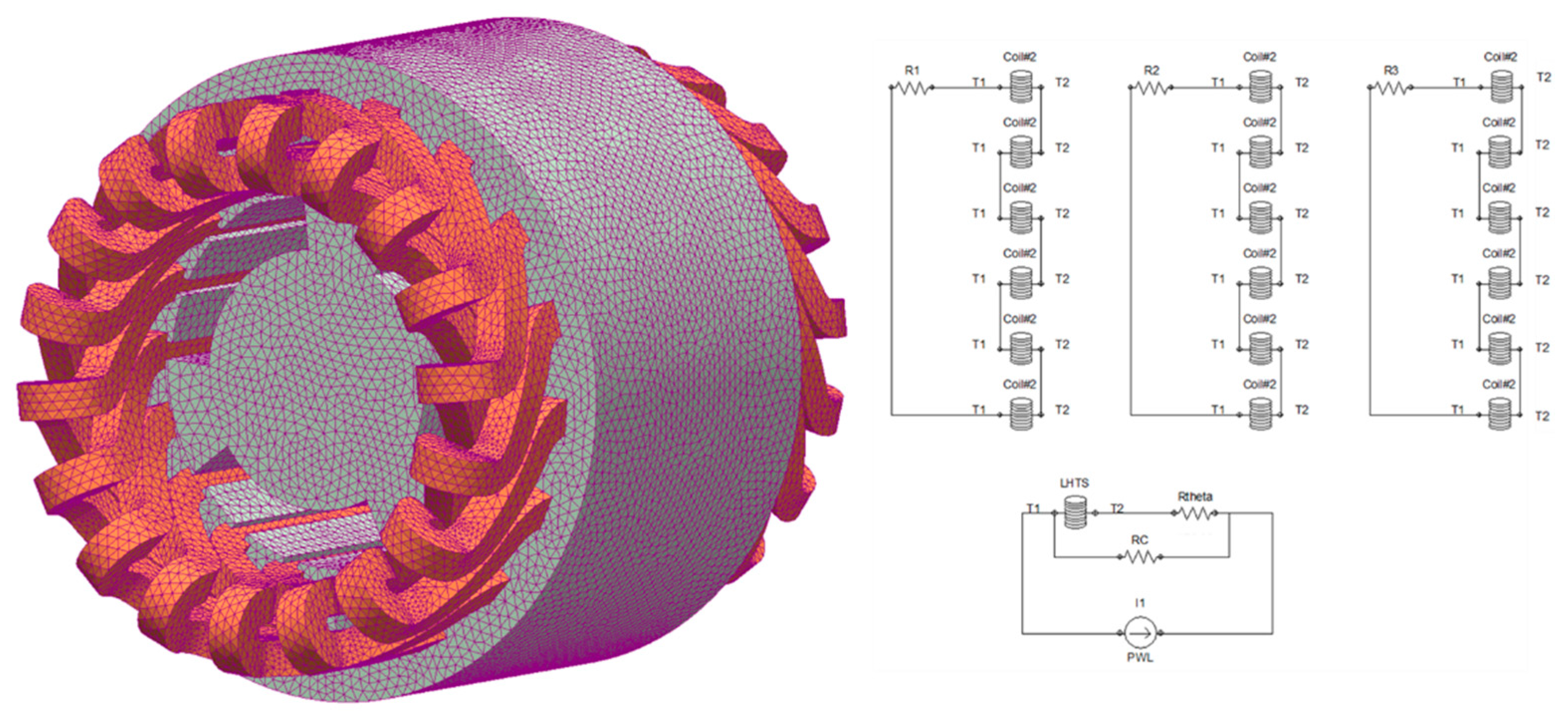
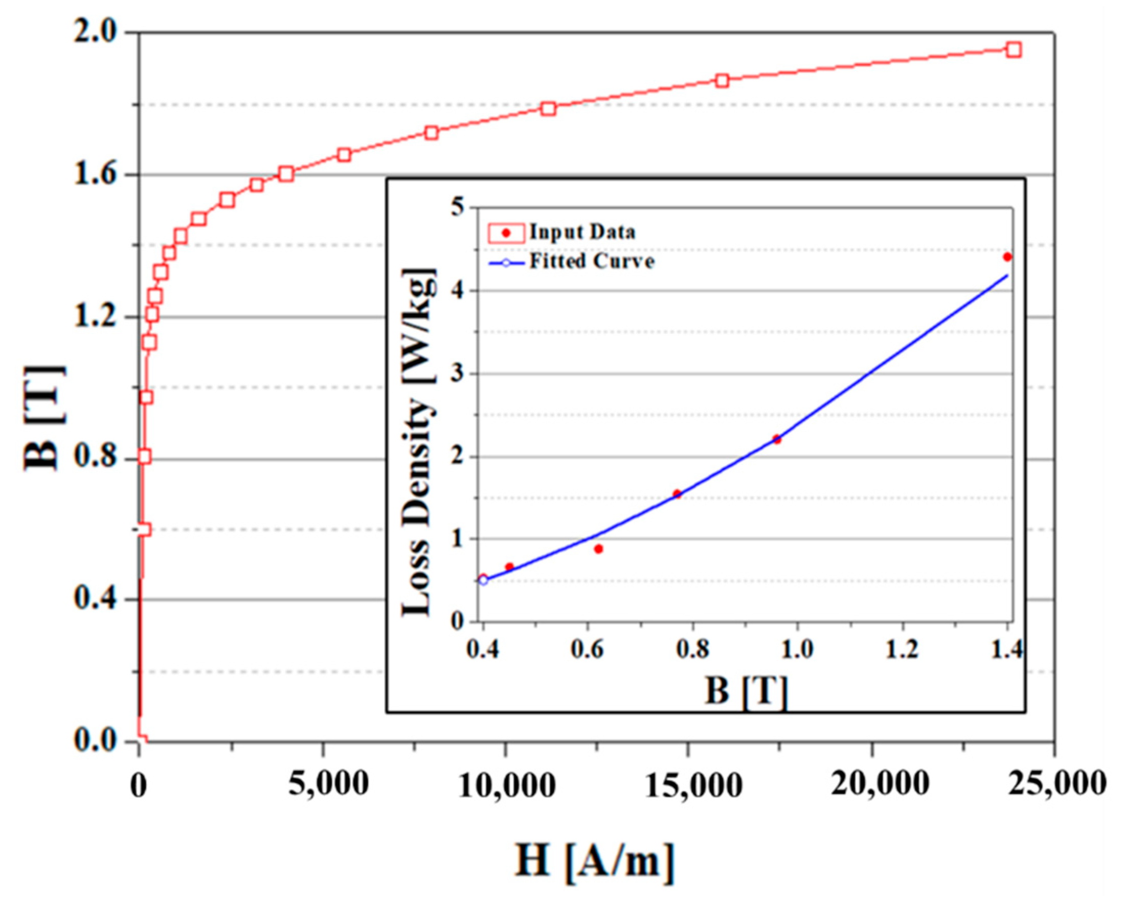
3.2. Simulation Model of the HTS HSM Using the NI HTS Field Coil

In this study, an HTS HSM was designed using a design method shown in Figure 6. This design process involves determining the maximum dimensions of the rotor yoke using the constraints such as the output power and rotational speed required by the HTS HSM. In this process, Poisson’s ratio and Young’s modulus of the material of the rotor yoke are used as parameters. Additionally, the size of the armature conductor and stator slot is determined in consideration of the allowable current density of the armature conductor. In addition, Von Mises stress analysis is performed to determine whether the rotor yoke maintains stability at the maximum rotational speed considering the safety factor. Since HTS HSM is an electrical rotating machine suitable for high rotation speed, this step is included in the overall design process. Then, the tangential stress of the rotor yoke is calculated using the output power of the HTS HSM and the dimensional specifications of the rotor yoke. Additionally, the required value of air-gap field density can be calculated based on this tangential stress. The magnetomotive force (MMF) of the HTS field coil to generate the air-gap field density is calculated using a magnetic equivalent circuit model, and the HTS field coil is designed using the Ic-B-θ data of the 2G HTS wire. This design was carried out under steady-state state conditions, and the design result was modeled using a commercialized finite element analysis program, and transient characteristics were analyzed.
Table 2 shows the design specification of the 110 kW-class HTS HSM. The rated output power was determined in consideration of the possibility of manufacturing a demonstration machine. The phase and rotational speeds of the machine are 3 and 2400 rpm, respectively. Dimensions of rotor yoke and stator yoke were determined by the above-mentioned design process. The overhang structure of the rotor core was applied to enhance the output power and efficiency of the machine. Figure 7 shows the simulation results on output power and machine efficiency according to the overhang length for optimization of the rotor core design. Output power and electrical losses continue to increase as the overhang length increases up to 25 mm, and decreases when greater than 25 mm. On the other hand, except for mechanical loss, the machine efficiency was the highest, at 98.49%, under the 30 mm overhang condition. Taking into account the machine efficiency, the most suitable overhang length for the designed homopolar HTS HSM is 30 mm. In this model, it was shown that an MMF of about 26 kA·turn is required to generate an output power of 110 kW. Accordingly, an HTS field coil with 540 winding turns and an operating current of about 48 A was designed. In addition, to verify the design, von Mises stress analysis according to the maximum rotational speed of the rotor was performed. Figure 8 shows the analysis results regarding the mechanical stress of the rotor core at the rotation speed of 4800 rpm. It shows that the maximum stress level of the designed rotor core is smaller than the 450 MPa, which is the yield strength of the rotor material.
Figure 9 shows the simulation model of the designed 110 kW HTS HSM. For this simulation, MagNet, which is a commercial electromagnetic analysis software, was used. In this model, the maximum element size was set to 15 mm, and non-oriented silicon steel was applied as the ferromagnetic material for the rotor and stator. The magnetic property and iron loss property of the ferromagnetic material were used with data embedded in MagNet software. Figure 10 shows the B–H curve and iron loss curve according to the peak value of the alternating magnetic field. The electrical resistance of the HTS material was set to zero using the user material-setting function, and the characteristic resistance of the NI field coil was obtained from Equation (1) [28] and the experimental results of test coils in Section 2. From Equation (1), the contact surface resistances of each coil are obtained to be 1.56, 1.83, and 4.34 µΩ·m2, respectively.
R C = i = 1 N R c t 2 π r i w d
where wd, and ri are the width of HTS tape, and the radius of the i-th turn of a HTS coil, respectively. Therefore, the characteristic resistance of the HTS field coil with the winding method used in Coil II, Coil III, and Coil IV can be determined as 0.78, 0.91, and 2.16 μΩ, respectively. These values were applied as RC values in the lumped circuit of HTS coils in the simulation model. The model was simulated using a transient 3D with a motion solver. In order to reduce the computational time, the time step was set to 100 s, and the rotation speed of the rotor was set to 0 rpm in the section before the HTS field coil was fully excited. Additionally, in the section after the HTS field coil was fully excited, the time step was set to 0.1 ms, and the rotor was set to move at the rated rotation speed of 2400 rpm.
The cooling method for the HTS field coil of the designed HTS HSM is considered cooling by liquid nitrogen (LN2). Therefore, an LN2 cryostat was designed based on thermal loads. The thermal loads are calculated by the equations below [29].
Q cl = ( ρ cl l cl I 2 / S cl k cl A cl ( T h T l ) / L cl ) 2 + 2 I ρ cl k cl ( T h T l )
Q k = N l A l k l ( T h T l ) / L l
Q r = σ ( T h 4 T l 4 ) / ( ( 1 ε h ) / ε h S h + ( 1 / ε l + 2 N / ε N N ) / S l )
where Qcl, and Qk are the thermal loads by the conduction heat transfer through a pair of current leads and the leading-in tubes, respectively. Qr is the thermal load by the radiation heat transfer of a vessel. To reduce the radiation heat loss, multi-layer insulation (MLI) in the vacuum space was considered. According to Equation (4), the radiation heat loss in the cryostat was calculated to approximately 1.21 W when five layers of MLI were inserted into the vacuum space. The conduction heat losses through a pair of current leads and the leading-in tubes were estimated to be approximately 2.93 W, 5.07 W, respectively. Figure 11 shows the designed LN2 cryostat.

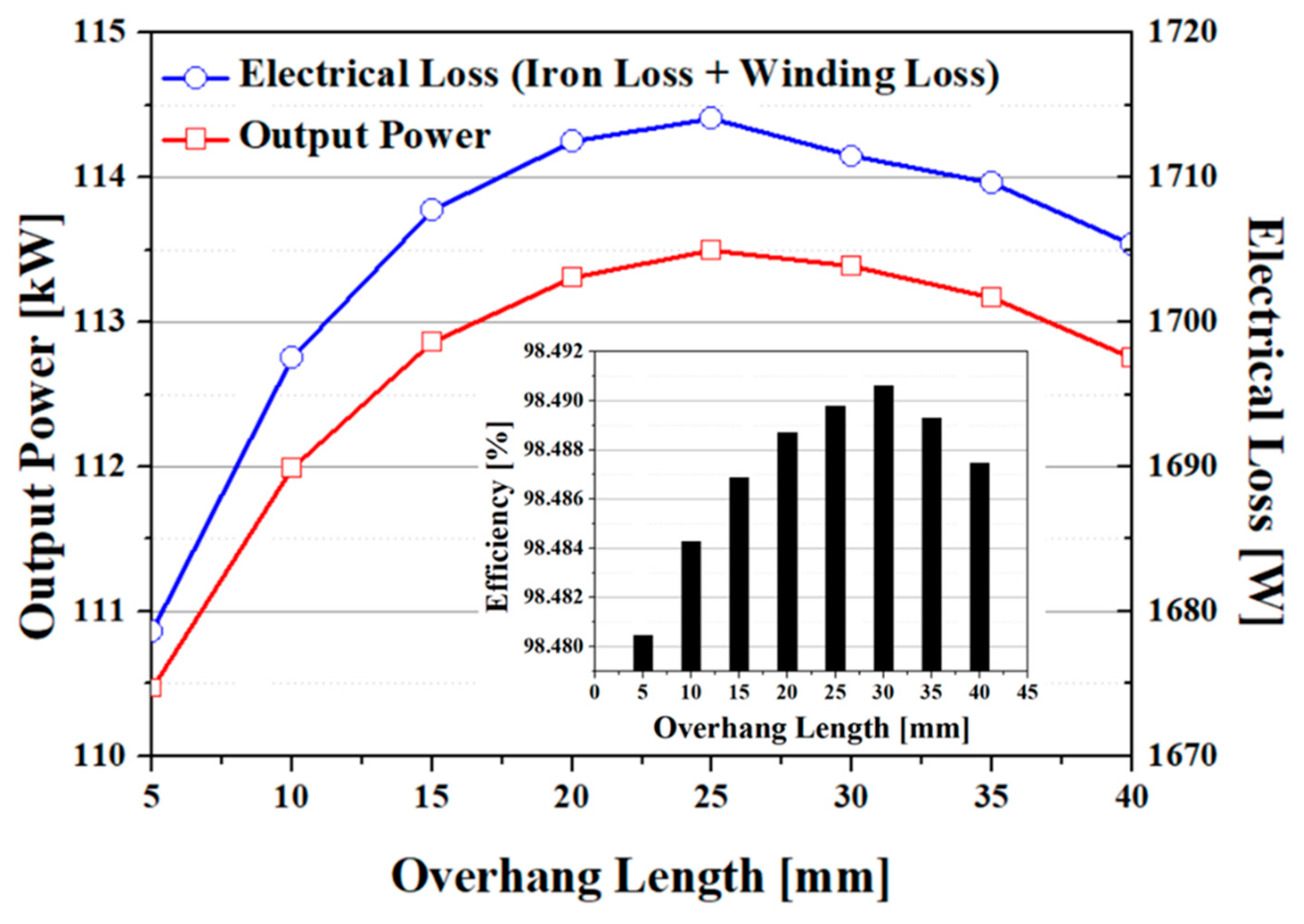
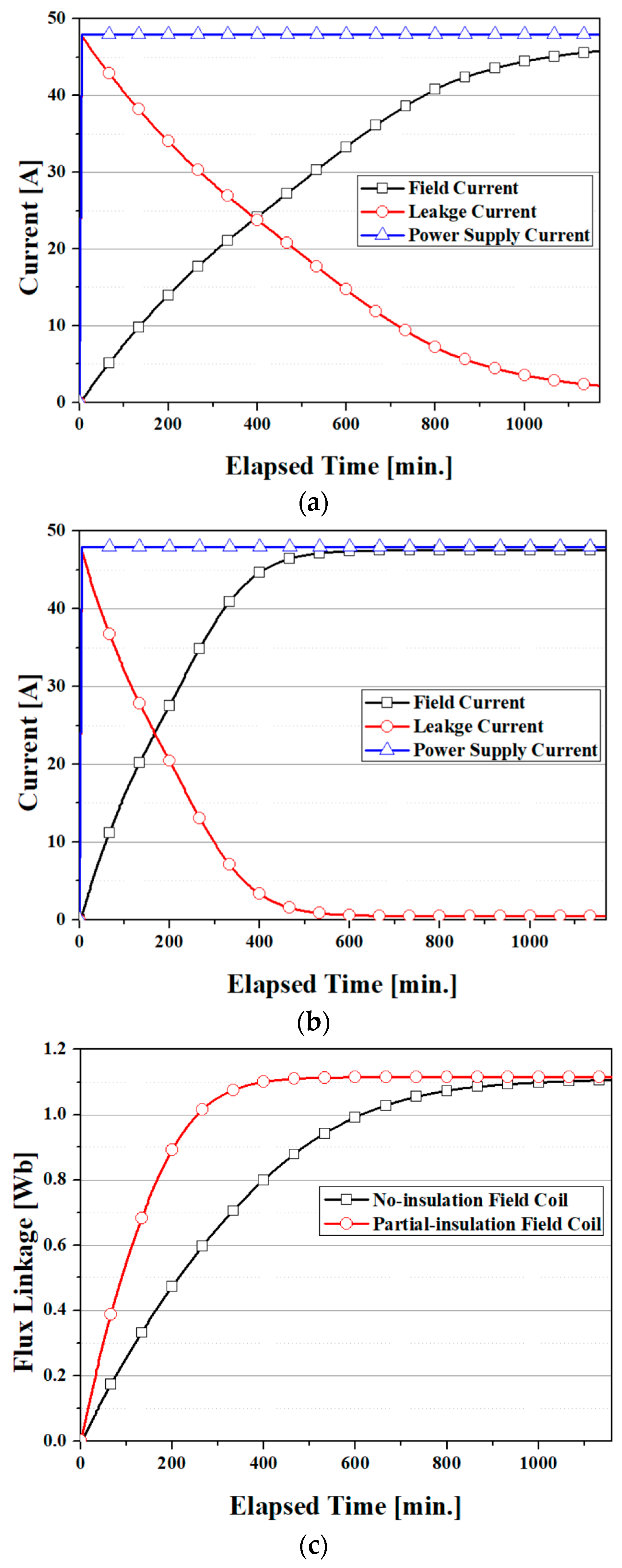
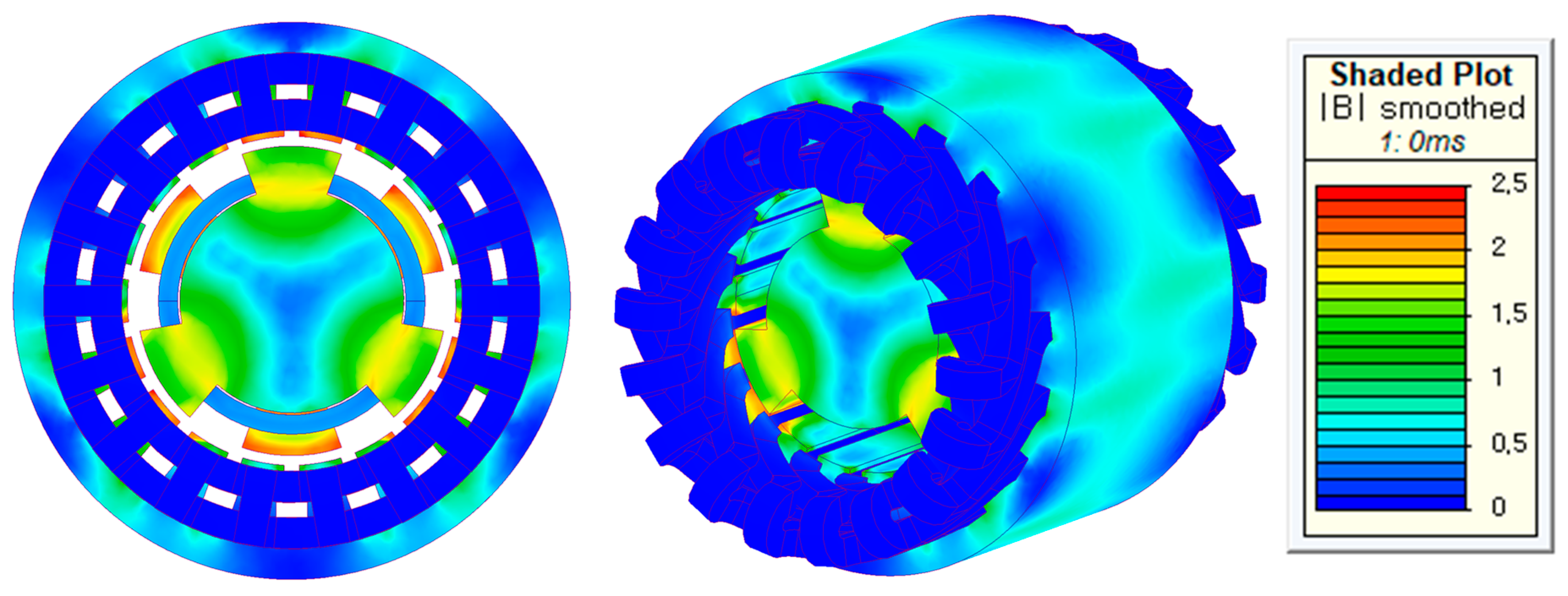
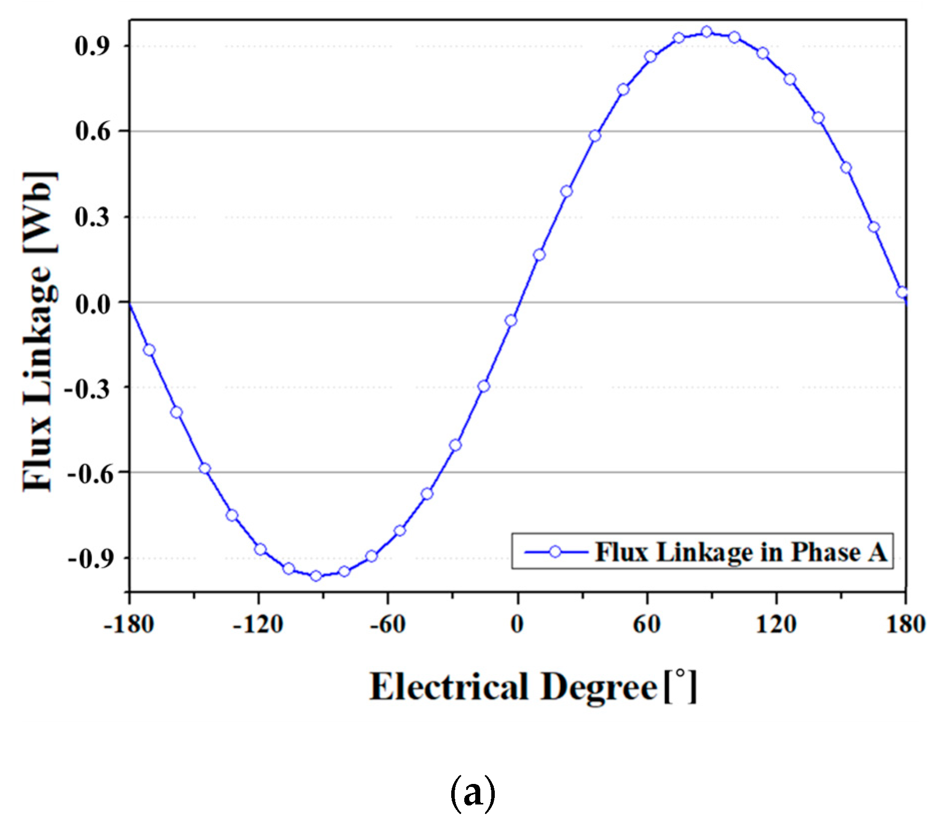
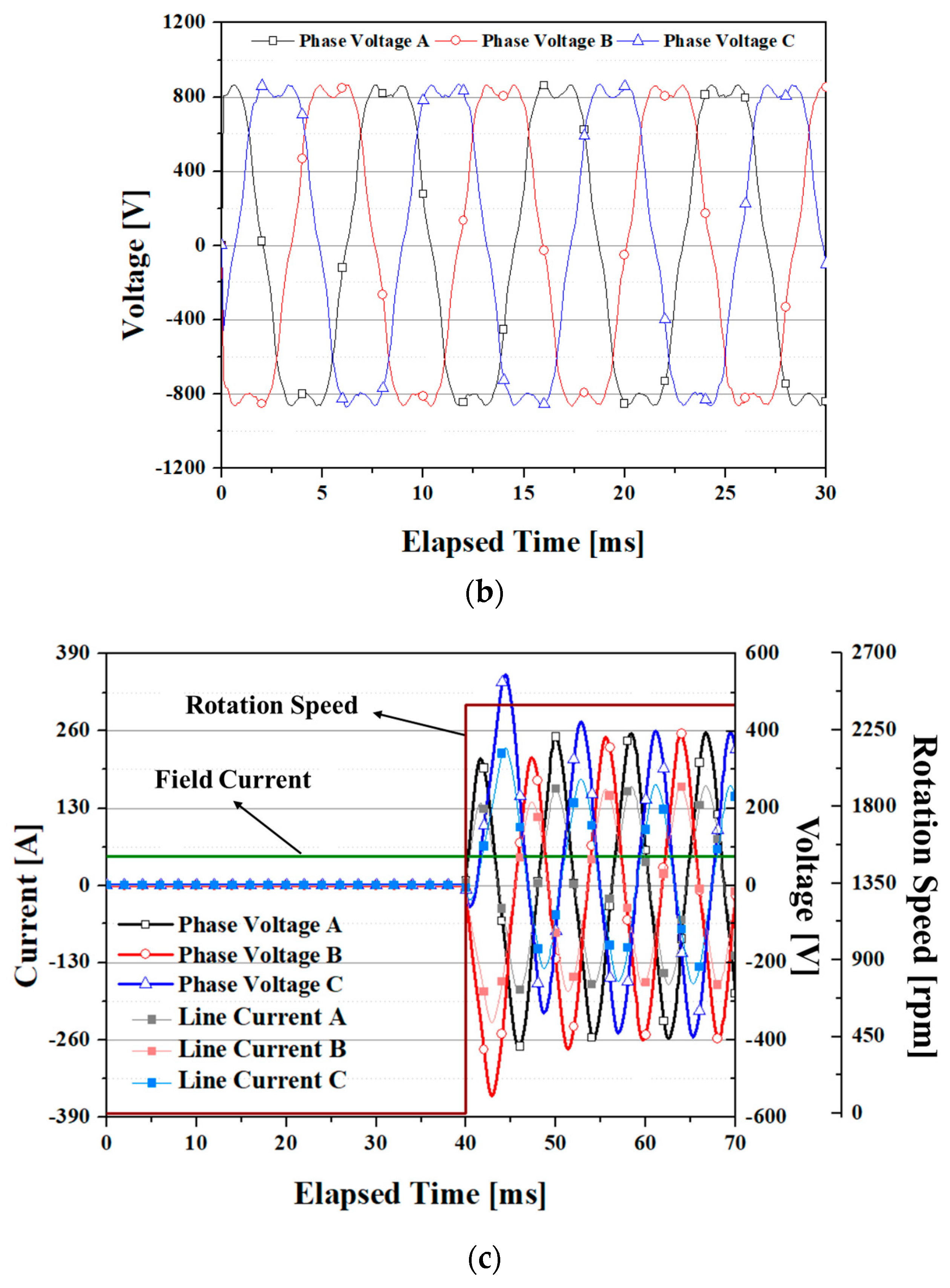
3.3. Results and Discussion

In this study, a 3D FEA simulation model linked with an electrical circuit analysis model was built based on the designed result, and the operating characteristics of the HTS HSM to which the NI HTS field coil was applied were analyzed. In this model, the NI HTS field coil was modeled based on the lumped circuit model of the NI coil. Figure 12a,b shows the current charging characteristics of the HTS HSM. Figure 12a is the simulation results of the HTS HSM using NI field coil, and Figure 12b is the simulation results of the HTS HSM using PI field coil in which the NI coil is insulated once every four turns. The model to which the fully insulated HTS coil is applied is not shown because there is no charging delay phenomenon. The time constant for the field current of the HTS coil to reach 63.2% of the target value after the power supply current reached the set value was about 536 min in the model to which the NI coil was applied. Additionally, the time constant value was improved to 224 min in the model to which the PI HTS field coil is applied, which is 42% compared to the NI model. Figure 12c shows the flux linkage in the phase A armature winding of each model. This shows that the speed at which the magnetic flux generated in the HTS field coil by the field current is linked to the armature winding is about 2.4 times faster in the PI model than in the NI model. Despite this improvement effect, it was found that it took more than 7 h to fully excite the HTS field coil, which means that much time is needed for the initial starting of the machine. Additionally, this also shows that it is virtually impossible to control the machine by regulating the field current. Therefore, it is necessary to consider a structure capable of controlling the flux using auxiliary winding [29,30].
In this section, the steady-state characteristics of the designed HTS HSM after the HTS field coil is fully excited were analyzed and investigated. Figure 13 shows a simulation result on the magnetic field distribution, and Figure 14 shows the simulation results on the flux linkage, no-load voltage, and phase voltage/line current in a resistive load condition, respectively, performed to examine characteristics in generator mode. In the simulation of phase voltage/line current in a resistive load condition, given that motion of the rotor starts immediately after the current in the HTS coil is fully excited, the output value differs for each phase up to about 15 ms due to the transient response (step response) component. From the simulation results, it is confirmed that the designed HTS HSM generates an output power of 110 kW in an operating condition. Additionally, it can be seen that the HTS HSM to which the NI HTS field coil is applied has the same operating characteristics as the HTS HSM to which the insulated HTS field coil is applied under normal operating conditions after the HTS field coil is fully excited.

4. Conclusions

In this paper, the feasibility of an HTS HSM using NI HTS field coil was investigated. Although the NI HTS coil is expected to make the paradigm shift of the development of many HTS electrical machines due to its strong self-protection characteristics, it is difficult to apply to actual electrical machines due to its inherent charge/discharge delay. Until now, many studies have been made to improve the charging/discharging delay phenomenon of NI HTS coils, but few studies have been completed at the system level. In this study, the feasibility was investigated based on the HSM model, which has the advantage of applying the HTS field coil due to the stationary field coil structure. In order to make a simulation model of HSM using the NI HTS field coil, the small-scale coils were tested. The characteristic resistance of the NI HTS coil and partial-insulation coils were calculated based on the test results of the HTS coils, and these were applied to the simulation model. A 110 kW class HTS HSM was designed, and a finite element analysis combined with an electrical circuit analysis was performed. The analysis results showed that the operating characteristics of the HTS HSM to which the NI HTS field coil is applied could be improved by using the partial-insulation method. However, the improvement effect using the partial-insulation winding method generally has a trade-off relationship with the quench-protection performance of the NI HTS coil. Therefore, additional research on the quench-protection properties for the HTS HSM proposed in this study is required. In addition, despite these improvements, applying the NI HTS field coil in terms of output control of the machine may cause problems because immediate output control is not possible. Therefore, it is necessary to study the application of auxiliary field winding for output control. This study is expected to be a reference for the development of future electrical machines using NI HTS coils.

Funding

This work was supported by the National Research Foundation of Korea (NRF) grant funded by the Korea government (MSIT) (No. 2021R1F1A1052767), and the Korea Medical Device Development Fund grant funded by the Korea government (the Ministry of Science and ICT, the Ministry of Trade, Industry and Energy, the Ministry of Health & Welfare, the Ministry of Food and Drug Safety) (Project Number: 1711138068, KMDF_PR_ 20200901_0063).

Conflicts of Interest

The author declares no conflict of interest.

Nomenclature

σ y i e l d Yield strength
vPoisson’s ratio
ρDensity of rotor material
n0The number of armature conductors per slot
I0Total current per slot
rOuter radius of rotor
lEffective length of rotor
ΩMechanical angular speed
EYoung’s modulus
kSafety factor
SCuCross-sectional area of armature conductor
JCuThe allowable current density of armature conductor
yjSlot height
wslotSlot width
βPacking factor
σFtanTangential stress of rotor
ISRMS value of phase current
qThe number of slots
cos φPower factor
ρclElectrical resistivity of the current lead
lclLength of the current lead
ITransport current through the current lead
SclCross-sectional area of the current lead
kclThermal conductivity of the current lead
ThTemperature at the high-temperature part
TlTemperature at the low-temperature part
σStefan–Boltzmann constant (5.67 × 10⁻⁸ W·m−2·K−4)
εhEmissivity of the vessel
εNEmissivity of MLI
NNo. of MLI layers
ShSurface area of the high-temperature part
SlSurface area of the low-temperature part
AlCross-sectional area of a signal line or a leading-in tube
klThermal conductivity of a signal line or a leading-in tube
LlLength of a signal line or a leading-in tube

References

  1. Kim, Y.-G.; Hahn, S.; Kim, K.L.; Kwon, O.J.; Lee, H. Investigation of HTS racetrack coil without turn-to-turn insulation for superconducting rotating machines. IEEE Trans. Appl. Supercond. 2011, 22, 5200604. [Google Scholar]
  2. Bang, J.; Kim, S.; Jang, J.Y.; Hwang, Y.J.; Cho, M.; Kim, J.; Lee, J.T.; Ahn, M.C.; Lee, S.; Hahn, S. Field Measurement and Analysis of a 3 T 66 mm No-Insulation HTS NMR Magnet With Screening Current and Manufacturing Uncertainty Considered. IEEE Trans. Appl. Supercond. 2019, 29, 4601305. [Google Scholar] [CrossRef]
  3. Quddes, M.R.; Sekino, M.; Ohsaki, H.; Kashima, N.; Nagaya, S. Electromagnetic Design Study of Transverse Flux Enhanced Type Superconducting Wind Turbine Generators. IEEE Trans. Appl. Supercond. 2011, 21, 1101–1104. [Google Scholar] [CrossRef]
  4. Fukui, S.; Ogawa, J.; Sato, T.; Tsukamoto, O.; Kashima, N.; Nagaya, S. Study of 10 MW-Class Wind Turbine Synchronous Generators with HTS Field Windings. IEEE Trans. Appl. Supercond. 2011, 21, 1151–1154. [Google Scholar] [CrossRef]
  5. Kim, J.M.; Jang, J.Y.; Lee, S.; Hwang, Y.J. Characteristic analysis of an HTS flux-switching synchronous generator with NI-type HTS field coils. IEEE Trans. Appl. Supercond. 2018, 28, 5202705. [Google Scholar] [CrossRef]
  6. Li, W.; Ching, T.W.; Chau, K.T.; Lee, C.H.T. A Superconducting Vernier Motor for Electric Ship Propulsion. IEEE Trans. Appl. Supercond. 2018, 28, 5201706. [Google Scholar] [CrossRef]
  7. Wang, Y.; Wang, C.; Feng, Q.; Li, X.; Ching, T.W. Design and Experiment of an HTS Flux-Switching Machine with Stationary Seal. IEEE Trans. Appl. Supercond. 2017, 27, 5201405. [Google Scholar] [CrossRef]
  8. Kim, J.M.; Jang, J.Y.; Chung, J.; Hwang, Y.J. A New Outer-Rotor Hybrid-Excited Flux-Switching Machine Employing the HTS Homopolar Topology. Energies 2019, 12, 2654. [Google Scholar] [CrossRef] [Green Version]
  9. Hwang, Y.J.; Jang, J.Y.; Jeon, H. Overhang effect analysis of a homopolar HTS synchronous generator using 3D finite element method. IEEE Trans. Appl. Supercond. 2010, 30, 5202105. [Google Scholar] [CrossRef]
  10. Lee, C.Y.; Lee, J.H.; Park, C.B.; Ryu, W.H.; Chung, Y.D.; Hwang, Y.J.; Ko, T.K.; Oh, S.-Y.; Lee, J. Conceptual design of superconducting linear synchronous motor for 600-km/h wheel-type railway. IEEE Trans. Appl. Supercond. 2013, 24, 3600304. [Google Scholar] [CrossRef]
  11. Torrey, D.; Parizh, M.; Bray, J.; Stautner, W.; Tapadia, N.; Xu, M.; Wu, A.; Zierer, J. Superconducting Synchronous Motors for Electric Ship Propulsion. IEEE Trans. Appl. Supercond. 2020, 30, 5204708. [Google Scholar] [CrossRef]
  12. Haran, K.S.; Kalsi, S.; Arndt, T.; Karmaker, H.; Badcock, R.; Buckley, B.; Haugan, T.; Izumi, M.; Loder, D.; Bray, J.W.; et al. High power density superconducting rotating machines-development status and technology roadmap. Supercond. Sci. Technol. 2017, 30, 123002. [Google Scholar] [CrossRef]
  13. Takematsu, T.; Hu, R.; Yanagisawa, Y.; Nakagome, H.; Uglietti, D.; Kiyoshi, T.; Takahashi, M.; Maeda, H. Degradation of the performance of a YBCO-coated conductor double pancake coil due to epoxy impregnation. Phys. C 2010, 470, 674–677. [Google Scholar] [CrossRef] [Green Version]
  14. Hwang, Y.J.; Jang, J.Y.; Song, S.; Kim, J.M.; Lee, S. Feasibility Study of the Impregnation of a No-Insulation HTS Coil Using an Electrically Conductive Epoxy. IEEE Trans. Appl. Supercond. 2017, 27, 4603405. [Google Scholar] [CrossRef]
  15. Sivasubramaniam, K.; Laskaris, E.T.; Shah, M.R.; Bray, J.W.; Garrigan, N.R. High-Temperature Superconducting Homopolar Inductor Alternator for Marine Applications. IEEE Trans. Appl. Supercond. 2008, 18, 1–6. [Google Scholar] [CrossRef]
  16. Hwang, Y.J.; Choi, S.; Jang, J.Y.; Lee, J.; Yoon, Y.S.; Kim, H.M.; Chung, Y.D.; Jo, Y.-S.; Jang, M.H.; Al-Ammar, E.A.; et al. A study on the superconducting synchronous generator with the fixed-type field coil. IEEE Trans. Appl. Supercond. 2012, 23, 5200305. [Google Scholar] [CrossRef]
  17. Choi, S.; Jo, H.C.; Hwang, Y.J.; Hahn, S.; Ko, T.K. A Study on the No Insulation Winding Method of the HTS Coil. IEEE Trans. Appl. Supercond. 2012, 22, 4904004. [Google Scholar] [CrossRef]
  18. Kim, K.; Kim, K.; Bhattarai, K.; Radcliff, K.; Jang, J.Y.; Hwang, Y.J.; Lee, S.; Yoon, S.; Hahn, S. Quench behavior of a no-insulation coil wound with stainless steel cladding REBCO tape at 4.2 K. Supercond. Sci. Technol. 2017, 30, 075001. [Google Scholar] [CrossRef]
  19. Lee, T.S.; Hwang, Y.J.; Lee, J.; Lee, W.S.; Kim, J.; Song, S.; Ahn, M.C.; Ko, T.K. The effects of co-wound Kapton, stainless steel and copper, in comparison with no insulation, on the time constant and stability of GdBCO pancake coils. Supercond. Sci. Technol. 2011, 22, 4904004. [Google Scholar]
  20. Kim, K.; Bhattarai, K.R.; Jang, J.Y.; Hwang, Y.J.; Kim, K.; Yoon, S.; Lee, S.; Hahn, S. Design and performance estimation of a 35 T 40 mm no-insulation all-REBCO user magnet. Supercond. Sci. Technol. 2017, 30, 065008. [Google Scholar] [CrossRef]
  21. Hahn, S.; Park, D.K.; Bascuan, J.; Iwasa, Y. HTS pancake coils without turn-to-turn insulation. IEEE Trans. App. Supercond. 2011, 21, 1592–1595. [Google Scholar] [CrossRef]
  22. Wang, X.; Haha, S.; Kim, Y.; Bascuan, J.; Voccio, J.; Lee, H.; Iwasa, Y. Turn-to-turn contact characteristics for an equivalent circuit model of no-insulation ReBCO pancake coil. Supercond. Sci. Technol. 2013, 26, 035012. [Google Scholar] [CrossRef] [PubMed]
  23. Hwang, Y.J.; Ahn, M.C.; Lee, T.S.; Lee, W.S.; Ko, T.K. Experimental study of the effects of alternating fields on HTS coils according to the winding insulation conditions. Supercond. Sci. Technol. 2013, 26, 085021. [Google Scholar] [CrossRef]
  24. Song, J.-B.; Hahn, S.; Kim, Y.; Miyagi, D.; Voccio, J.; Bascuan, J.; Lee, H.; Iwasa, Y. Dynamic Response of No-Insulation and Partial-Insulation Coils for HTS Wind Power Generator. IEEE Trans. Appl. Supercond. 2015, 25, 5202905. [Google Scholar] [CrossRef]
  25. Hahn, S.; Kim, K.; Kim, K.; Lee, H.; Iwasa, Y. Current Status of and Challenges for No-Insulation HTS Winding Technique. J. Cryog. Supercond. Soc. Jpn. 2018, 53, 2–9. [Google Scholar] [CrossRef] [PubMed] [Green Version]
  26. Zhang, Z.; Kim, C.H.; Kim, J.G.; Kvitkovic, J.; Pamidi, S.; Zhang, M.; Li, J.; Yuan, W. An Experimental Investigation of the Transient Response of HTS Non-insulation Coil. J. Supercond. Nov. Magn. 2017, 20, 387–393. [Google Scholar] [CrossRef] [Green Version]
  27. Wang, T.; Noguchi, S.; Wang, X.; Arakawa, I.; Minami, K.; Monma, K.; Ishiyama, A.; Hahn, S.; Iwasa, Y. Analyses of Transient Behaviors of No-Insulation REBCO Pancake Coils During Sudden Discharging and Overcurrent. IEEE Trans. Appl. Supercond. 2015, 25, 4603409. [Google Scholar] [CrossRef]
  28. Jang, J.Y.; Yoon, S.; Hahn, S.; Hwang, Y.J.; Kim, J.; Shin, K.H.; Cheon, K.; Kim, K.; In, S.; Hong, Y.-J.; et al. Design, construction and 13 K conduction-cooled operation of a 3 T 100 mm stainless steel cladding all-REBCO magnet. Supercond. Sci. Technol. 2017, 30, 105012. [Google Scholar] [CrossRef] [Green Version]
  29. Hwang, Y.J.; Jang, J.Y.; Lee, S. A Flux-Controllable NI HTS Flux-Switching Machine for Electric Vehicle Applications. Appl. Sci. 2020, 10, 1564. [Google Scholar] [CrossRef] [Green Version]
  30. Zhang, G.; Hua, W.; Cheng, M.; Liao, J.; Wang, K.; Zhang, J. Investigation of an Improved Hybrid-Excitation Flux-Switching Brushless Machine for HEV/EV Applications. IEEE Trans. Ind. Appl. 2015, 51, 3791–3799. [Google Scholar] [CrossRef]
Figure 1. Experimental setup and HTS coils for charging/discharging tests: (a) Coil I, (b) Coil II, (c) Coil III, and (d) Coil IV.
Energies 14 05658 g001
Figure 2. Simplified equivalent circuit diagram of HTS coils: (a) insulation HTS coil, (b) no-insulation HTS coil, (c) partial-insulation coil.
Energies 14 05658 g002
Figure 3. Charging/discharging test results of HTS coils: (a) Coil I, (b) Coil II, (c) Coil III, and (d) Coil IV.
Energies 14 05658 g003aEnergies 14 05658 g003b
Figure 4. Sudden discharging test results: (a) Coil I, (b) Coil II, (c) Coil III, and (d) Coil IV.
Energies 14 05658 g004
Figure 5. Fundamental structure of HTS homopolar synchronous machine.
Energies 14 05658 g005
Figure 6. Fundamental design process of the HTS homopolar synchronous machine.
Energies 14 05658 g006
Figure 7. Output power and electrical loss according to overhang length. Inset: efficiency vs. overhang length.
Energies 14 05658 g007
Figure 8. Mechanical stress analysis of the rotor core at 4800 rpm.
Energies 14 05658 g008
Figure 9. Field–circuit coupled FEA model of the designed NI HTS HSM using a lumped circuit model.
Energies 14 05658 g009
Figure 10. B–H curve of non-oriented silicon steel in the simulation model. Inset: iron loss properties.
Energies 14 05658 g010
Figure 11. Liquid nitrogen (LN2) cryostat for the HTS field coil.
Energies 14 05658 g011
Figure 12. Current and flux charging characteristics of the HTS HSMs: (a) current charging characteristics of the HTS HSM using the NI HTS field coil, (b) current charging characteristics of the HTS HSM using the PI HTS field coil, and (c) flux linkage in phase A.
Energies 14 05658 g012
Figure 13. Magnetic field distribution of the HTS homopolar synchronous machine.
Energies 14 05658 g013
Figure 14. Steady-state operating characteristics of the HTS homopolar synchronous machine: (a) flux linkage, (b) no-load voltage, and (c) phase voltage and line current in resistive-load condition.
Energies 14 05658 g014aEnergies 14 05658 g014b
Table 1. Specifications of the HTS coils.
ParameterCoil ICoil IICoil IIICoil IV
Insulating typeTurn-to-turn insulationNo-insulationInsulation every 8 turnsInsulation every 4 turns
Inductance~179 µH
Winding diameter65 mm
Winding turns40 turns
Critical current~74 A
HTS wire2G HTS wire
(width: 4.8 mm, thickness: 0.19 mm)
Table 2. Design specifications of the HTS HSM.
ItemValue
Rated output power110 kW
Phases3
Rated rotational speed2400 rpm
No. of poles6
Outer radius of rotor yoke190 mm
Length of rotor yoke170 mm
Overhang of rotor yoke30 mm
No. of stator yoke slots18
Depth of stator yoke slot103 mm
Width of stator yoke slot40 mm
No. of armature conductor per slot10
Outer radius of stator yoke350 mm
Publisher’s Note: MDPI stays neutral with regard to jurisdictional claims in published maps and institutional affiliations.

