1. Introduction
Fluidized bed combustion technology is the most successful technology for heat and power generation from multi-fuels, such as: fossil fuels (lignite, bituminous coal, anthracite, sub-bituminous coal and petroleum coke), peat, biomass (agro, wood) and also municipal waste with some challenges. In the last decade, it has been observed that the diffusion, jointly with the dynamic development of CFB boilers around the world, has led to the increase in capacity of single-unit CFB boilers [
1,
2,
3]. Recently, CFB boiler capacities increased up to 1000 MWe with supercritical and ultra-supercritical working medium parameters [
4,
5,
6,
7,
8,
9]. The fluidized bed technology is very efficient and economically preferable due to the high heat transfer rates that are attained from the fluidized bed to the active heat transfer surface. Supercritical pulverized coal combustion (PCC) technology has higher capital costs and some added risk due to the higher temperature and higher steam pressure. The higher steam pressure in subcritical PCC plants results in lower energy efficiency of 33%, compared with 45% for modern CFB combustion systems. The operating temperature of the CFB boiler varies between 760 and 870 °C, and it is half of the temperature inside conventional PC boilers (1300–1700 °C). This relatively low temperature is below the threshold where thermally induced NO
x forms. Thus, the fluidized bed designs represent a lower environmental impact compared to PCC plants. In addition, CFB boilers can utilize coal with high ash content in contrast to conventional pulverized coal units, which have to limit ash to a relatively low level. Among the most common heat exchangers used in combination with circulating fluidized bed (CFB) boilers are tube-type heat exchangers with tube bundles in different orientations (vertical or horizontal tube banks). In general, the smooth tubes forming the bundle are usually mounted in an in-line [
10,
11,
12] or in staggered arrays [
13,
14,
15] in CFB facilities. In the bubbling fluidized bed (BFB) literature, the staggered tube arrangement is primarily chosen for the studies on heat transfer characteristics, as discussed in [
13].
The fundamental knowledge of the heat flow from the fluidized bed to the bundle of submerged tubes is necessary and provides important information for the optimum design and proper operation of fluidized bed heat exchangers (FBHE’s) in a CFB boiler. It should be noted that the bed-to-wall heat transfer process is very complicated due to the complex nature of fluidized beds (such as bed particle size, sphericity particle, the specific heat of particle, gas thermal properties, fluidization velocity, bubble dynamics, particle residence time at the heat transfer surface, heat exchanger geometry and also the type of gas distributor) and complexity of heat transfer mechanisms occurring in the FBHE’s. Moreover, the mechanism of heat transfer from the fluidized bed to tube surface depends upon the variations in heat transfer tube design, such as diameter, pitch, shape, spacing, tube array position, orientation and material type. Thus, there are the various processes and technical details of fluidized bed heat exchangers, which can allow the efficient production of energy and economic gains in large-scale CFB units.
There is an abundance of studies conducted toward the understanding of the heat transfer behavior in fluidized bed heat exchangers, but they are limited to the investigations of laboratory scale, especially for the single horizontal tube or cylinder immersed in bubbling fluidized beds. Data reported by Stenberg et al. [
16] show that the calculated heat transfer coefficient is affected by the particle size, the bed temperature, the kind of bed material and the superficial gas velocity. The authors of [
16] showed that the heat transfer rate increased from 768 to 1858 W/(m
2K) with decreasing bed particle diameter from 0.327 to 0.123 mm, increasing bed temperature (400–900 °C) and also increasing fluidization velocity, up to 0.15 m/s. Merzsch et al. [
17] conducted fundamental research on the influence of experimental conditions (such as moisture and particle diameter) on the variation of heat transfer coefficient for three different diameters of single horizontal tubes (outer diameter: 14, 21.3 and 33.7 mm) in fluidized beds. Other authors [
18] developed a heat transfer model based on the cluster renewal approach to the prediction of time-averaged convective heat transfer coefficients for a small horizontal tube (
dt = 8 mm). In early publications, Grewal and Saxena [
19,
20] proposed the empirical correlations for the maximum heat transfer coefficient for a single tube and the tube bundle submerged in a fluidized bed with fine particles (75 <
Ar < 20,000). Kurosaki et al. [
21] performed experiments with a single horizontal heated circular cylinder with a Reynolds number varied between 90 and 3770. It was observed that maximum values of local heat transfer coefficient occurred on the front stagnation point and the smallest on the side of the cylinder in the case of high
Re. At a low Reynolds number, the maximum values occurred at equatorial lateral zones of the cylinder and the smallest on the upstream side. Furthermore, the Reynolds number indicates the correlation between the local behavior of bed particles near the cylinder surface and heat transfer augmentation. The flow pattern of bed particles and gas phases near the cylinder wall can be classified into three regions. In the still region (
Re < 200) particles do not move. The sliding region occurs between the still and mixing regions. Sliding flow patterns depend upon the Reynolds number. When the Reynolds number covers a range of 430–700, bed particles slide by oscillating from side to side. In the range of 700 <
Re < 950, bed particles come down and hit the rear stagnation point. At Reynolds number 950 <
Re < 1400, the sliding direction of the bed particles becomes random. The mixing region is subdivided into three subregions: (i) first subregion (200 <
Re < 240), where moving and still bed particles exist alternatively in the direction of the axis of the cylinder; (ii) second subregion (
Re > 240), particles spread to the front and rear of the cylinder; (iii) and the third subregion (
Re > 1400), which covers the whole circumference of the cylinder. The high local heat transfer rate can be recorded at the boundary between the sliding and mixing regions [
21]. Nevertheless, the position of maximum local heat transfer coefficient shifts toward the cylinder rear with the increase of superficial gas velocity in fluidized beds. The same trend variation of local heat transfer coefficients around a horizontal cylinder immersed in a bubbling fluidized bed is reported by Di Natale et al. [
22]. Wiman et al. [
23] reported the effect of system pressure on average heat transfer coefficient at different operating conditions (fluidization velocity, particle sizes and tube bundle structures). The obtained heat transfer data indicated that the average heat transfer coefficient increases with the increasing system pressure. Furthermore, Bao et al. [
24] observed that the fluidization number corresponding to the
hmax increases as the system pressure increases. Another work [
25] developed an empirical correlation for Nusselt number versus Archimedes number and
dt/dp for two different horizontal cylinders size on the basis of the measurements made in pilot-scale and laboratory-scale CFB facilities. In the scientific work [
10], a new concept of an external heat exchanger for a circulating fluidized bed boiler was developed. The findings showed that the heat transfer absorption might be controlled by the fluidization velocity, both in the fluidized bed heat exchanger and in the overflow part of the loop seal. It is worth noting that the proposed new fluidized bed heat exchanger concept may be applied to commercial CFB combustors.
There is currently considerable interest in heat transfer characteristics under large-scale bubbling fluidized beds conditions. It is a result of the limited availability of experimental data for FBHEs in the published literature due to commercial reasons. However, the selected experimental data deal with heat transfer characteristics for large-scale CFB units that are usually presented under different boiler loads only [
4,
8,
12,
14,
26]. Only a few papers [
15,
27] discussed the heat transfer between the horizontal tube bundle and the fluidized bed in detail.
Until now, there is still a lack of operating data guidelines for commercial FBHEs in relation to the accomplishment of optimal heat transfer conditions for power generation in an environmentally acceptable fashion. Therefore, one of the principal challenges in scale-up or designing FBHE systems is a lack of adequate data on heat transfer rates to tube banks. As described above, most of the published findings deal with laboratory scale, especially for single tubes or cylinders.
The present study herein is intended to fill this gap and improve mechanistic heat transfer models based on the packet renewal approach. The proposed heat transfer model takes into account tube bundle structure characteristic coefficients apart from bubble dynamics (bubble fraction) and solids mixing process (emulsion-wall contact time with horizontal smooth tube bundle). The accuracy in dimensioning the active heat transfer surfaces affects the extra construction cost of a power plant by reason of heat exchangers oversizing. Therefore, the main goal of the article is to provide reliable data that can be used to validate the procedures and the empirical correlations used to design fluidized bed heat exchangers for large-scale CFB boilers. Hence, there is a need to accurately understand the bed-to-tube heat transfer mechanisms in order to enhance the heat transfer at external heat exchanger operating conditions.
2. Formulation of Mechanistic Heat Transfer Model
Gas-phase and solids motions in a fluidized bed are altered by the presence of a submerged heat transfer surface. The same applies to gas bubbles sizes and their distributions in fluidized beds. In the case of horizontal tube banks, gas bubbles break into smaller ones and are distributed over the bed cross-section much more homogeneously compared to a bed without immersed surfaces. As shown in
Figure 1, the gas-solid flow around a single horizontal smooth tube can be characterized by the following features: (i) formation of a defluidized cap of bed particles on the downstream surface of the tubes with low heat transfer rate, (ii) appearance of a thin gas film or gas cushion at the upstream surface of the tubes, and (iii) gas bubble forming at the horizontal diameter points caused by the local acceleration of the flow of fluidizing gas.
The gas-solid flow in the vicinity of horizontal tubes has essential heat transfer implications. The high values of bed-to-tube heat transfer coefficients will occur at the sidewalls of the horizontal tubes and are associated with the low gas velocities occur. Meanwhile, the low values of heat transfer rate can be found at the top and bottom regions of the tube where is located stagnant cap of bed particles and thin gas film.
The mechanistic heat transfer model is used to describe the average bed-to-tube heat transfer coefficient and is based on the packet renewal theory proposed by Mickley and Fairbanks [
28]. All heat transfer mechanisms responsible for heat flow to the tubular surface immersed in a fluidized bed is described below as follows. In the packet renewal model, bed particles, called parcels of emulsion phase, are brought to the active heat transfer surface due to fluidizing gas dynamics. After remaining there for a short residence time (
te), the parcels of emulsion phase will be swept away by gas bubbles and moved back into the main body of the bed and at the same time interchanged with “
fresh” particles (hot packets) from the body of the bed. In this model, for analytical purposes, the packet is considered homogeneous. The corresponding equation to express the emulsion contacting time with the heat transfer surface at the bottom region of the tube, in correlation with the Froude number, can be written as follows [
29,
30,
31]:
Here,
dp denotes Sauter mean particle diameter,
dt represents tube diameter,
g is the acceleration due to gravity,
Ug refers to superficial gas velocity and
Umf is the minimum fluidization velocity. In the aforementioned Equation (1),
A represents a dimensionless parameter, which is calculated using the following relationship [
32]:
where
Ab is the bed cross-sectional area and
At means projected area of the tube surface. In Equation (2), the value of
At is estimated by the following expression:
where
dt means tube diameter,
lt represents tube length and
n denotes the number of tubes. The parameter
A gives us information on the local formation of bubbles between horizontal tube bundles at superficial gas velocities below the minimum fluidization velocity (distributor level). Furthermore, the empirical factor
A takes into account the effects of tube diameter and particle shape. It has the tendency to decrease as the tube diameter increases, and at the same time, the bed particles are more likely to closely approximate to the spherical shape.
Three basic assumptions that refer to parcels of emulsion phase behaviors at the horizontal tube surface were defined by the authors: (i) emulsion phase stillness, (ii) sliding of the bed particles along the heat transfer surface and (iii) interaction between the bubbles and the emulsion phase. Thus, the packed particles’ contact time with the horizontal tubes is dependent on the particle motion adjacent to a submerged horizontal tube bundle, which is resulted from local fluctuations in the gas bubble fraction. To determine the bubble fraction, we can use the following formula [
27]:
where the symbols used in Equation (4) are explained in aforementioned Equation (1).
In fluidized bed systems, heat is transferred to the immersed tube bundle by packets of emulsion phase, by gas percolating between the bed particles and the tube surface and also by means of gas bubbles, as is depicted in
Figure 2.
The average heat transfer coefficient between the immersed tube bundle and the fluidized bed is defined as:
where
ξ represents the tube bundle structure characteristic coefficient,
htop is heat transfer coefficient at the top tube section,
hbottom refers to heat transfer coefficient at the bottom tube section,
nr means number of tubes rows,
nsplash and
ndense denote number rows of tubes immersed in splash zone and dense phase, respectively. The value of a tube bundle structure characteristic coefficient
ξ is calculated using the following Equation (6):
Here,
ph denotes the horizontal pitch of tubes and
pv represents the vertical pitch of tubes. For the case of the staggered tube bundle configuration, not only the horizontal pitch but also the vertical pitch influences the value of the average bed-to-tube heat transfer coefficient. Thus, the average heat transfer coefficient is reduced with a decrease in horizontal pitch. On the other hand, the reduction in the value of
havg, is more pronounced at a low vertical pitch of the tube bundle. It is worth mentioning that Equation (6) has also been used in other works [
24,
33].
Due to the fact that the horizontal smooth tubes in the top section are operated under splash zone conditions (
nsplash = 4), from here, the average heat transfer coefficient
htop is obtained from the following empirical correlation [
15,
27,
34]:
where
Re is Reynolds number,
Pr denotes Prandtl number,
ce and
cg are heat capacity for emulsion phase and gas phase, respectively. Other denotations used in Equation (7) are explained in Equation (1). The correlation (7) is valid for the investigated tube bundle geometry and can be used for a wide range of experimental conditions: 0.97 ≤
Re ≤ 12.56, 93.46 ≤
dt/
dp ≤ 157.73, 0.67 ≤
ce/
cg ≤ 0.79 and
Pr = 0.71. From the simple relation for the Nusselt number given in Equation (8), it is possible to calculate the bed-to-tube heat transfer coefficient at the top tube bundle for each empirical correlation:
In the dense phase of the fluidized bed, a submerged horizontal tube bundle without fins (
ndense = 20) remains in the emulsion phase, where the bubbles and the orientation of bed particles are the same as that in the packed bed. In this case, it is generally accepted that the average bed-to-tube heat transfer coefficient for bottom tube section
hbottom is expressed as a combination of three additive components: packet particles convection
he, gas convection
hg and thermal radiation
hr:
All three individual heat transfer mechanisms will be discussed in the following section. In Equation (9) above,
δb denotes bubble fraction and is determined with Equation (4) in agreement with the classical two-phase theory for aggregative fluidization [
35,
36].
The convection heat transfer from particle packet (emulsion phase) to the horizontal tube bundle in the bottom section is estimated by Equation (10), which is given by [
37] as:
where
te is emulsion contact time with heat transfer surface,
ce denotes heat capacity of emulsion,
ke means emulsion thermal conductivity and
ρe represents the density of emulsion phase.
The various variables (physical and thermal properties) are required for the determination of the convective heat transfer coefficient of the emulsion phase (
he) by the packet renewal theory. In summary, for a horizontal tube bundle immersed in a fluidized bed, the value of
he is determined with the equations given in
Table 1.
The gas convection component of the heat transfer coefficient for the bottom tube section is estimated from Equation (11) proposed by Baskakov et al. [
31], given below:
where
dp means Sauter mean particle diameter,
kg denotes thermal conductivity of gas phase,
Ar represents Archimedes number and
Pr refers to Prandtl number. In spite of the fact that the relationship (11) is not affected by a change in tube diameter or length, many scientists [
41,
42] have used this equation to estimate the gas convection mode in heat transfer over a wide range of fluidization conditions.
In the packet renewal approach, the radiative heat transfer coefficient of the horizontal tube bundle immersed in a dense bed inside FBHE is calculated with Equation (12), whereas individual thermal parameters of bed particles and tube surface are calculated with formulas listed in
Table 2.
In Equation (12), σ represents Stefan Boltzmann constant, eb is the effective emissivity of bed particles, ew denotes emissivity of the tube surface, Teb refers to effective bed temperature and Tw means wall temperature.
In this heat transfer study, the value of effective emissivity of bed particles is estimated on the assumption that the emissivity of the bed particles is equal to 0.8. The emissivity of the horizontal smooth tube wall is assumed as 0.7. Due to the fact that reheater RH II is operated at similar operating parameters (i.e., bed temperature, suspension density) as the water membrane wall inside the CFB furnace, the authors used the first formula from the bottom of
Table 2 to predict the wall (metal) temperature at Δ
Tw =30 °C, as suggested by Basu [
44]. In this study, the bed temperature varied between 918 and 1094 K, whereas the suspension density covered a range of 793–1006 kg/m
3. In the case of a tube bundle with fins, the difference between the internal and external temperatures of the tube surface Δ
Tw (superheater and reheater), made from carbon steel or steel alloy, is calculated with equations described in [
45]. Furthermore, a fluidized bed heat exchanger type Foster Wheeler is integrated into the combustion chamber. The radiation mode in heat transfer mechanisms at a low bed temperature (
Tb < 873 K) is negligible, and for higher bed temperatures (
Tb > 873 K) is obtained from a simple relation (12). Thus, to get a more precise calculation of the heat transfer coefficient
hbottom at a high bed temperature, the radiative contribution is added to the convective contribution, jointly with making up the heat transfer component for the bottom tube bundle section operated under dense bed conditions [
44,
46].
3. Input Data to Heat Transfer Modeling
In order to expand the findings of the heat transfer data from large-scale units and their application in the overall heat exchangers design procedure, a mechanistic model for the fluidized bed heat exchanger was developed using packet renewal theory. The mechanistic heat transfer model to predict the average heat transfer coefficient from the bed to the horizontal smooth tube bundle accounts for the effect of system pressure on different hydrodynamic variables. Furthermore, the packet renewal approach is improved by adding a final correlation of
havg, the additional component with a tube bundle structure geometry characteristic. The authors proposed a heat transfer model for commercial FBHE systems accounting for the impact of gas density and volumetric void fraction of emulsion on packet particle convection and gas convection heat transfer coefficients under dense bed conditions. This model predicts the values of an average bed-to-tube heat transfer coefficient for a full-sized heat exchanger by incorporating both heat transfer from the packets particles, gas bubbles and radiative heat transfer external to the tube bundle. It is assumed that the FBHE system operates under constant pressure during each test, and fluidizing medium (air) is treated as an ideal gas. In order to simplify the complex problem of heat transfer from fluidized beds to immersed horizontal objects, the authors have used the following assumptions: (i) the particle packets and gas phase behave as a continuous flow fluidized bed, (ii) the gas temperature equals the particle packets temperature for a given examined condition since both phases are highly intermixed, (iii) at any given time, the heat transfer surface is covered by emulsion phase (particle packets) or gas bubbles, (iv) particle packets are brought into contact with the immersed horizontal tube surface by the motion of rising gas bubbles in the bed, (v) the gas convection contributes to the process of heat transfer by convective mixing, which augments the heat transfer in the gas gaps between the bed particles and the heat transfer surface and between neighboring particles, (vi) the heat capacity of packets is assumed to be equal to the solid heat capacity [
38], (vii) the bubble fraction in the fluidized bed is estimated in agreement with the classical two-phase theory for aggregative fluidization [
35,
36], (viii) in the emulsion phase, heat transfer is assumed to be composed of particle convection (whose motion is a direct result of gas bubble flow), gas convection due to the interstitial gas velocity and radiation [
27] and (ix) the density of an emulsion packet is not taken to be equal to the density of a loosely packed static bed of particles [
38].
In the mechanistic heat transfer model, the average heat transfer coefficient is predicted directly based on a large number of experimental findings under the examined conditions. In order to obtain the heat transfer characteristic in an external heat exchanger, eight performance tests are conducted when a 1296 t/h CFB boiler is operated under stable operating conditions. Based on the observations of the variability of operating parameters change-rate during the individual tests, the raw data are collected in agreement with the Shannon–Kotelnikov theorem [
47]. Each performance test lasted eight hours for six typical operating conditions of the fluidized bed heat exchanger in order to establish the repeatability of measurement data. The raw data were recorded online by means of a monitoring system over a period of time, and an arithmetic average value is used to calculate the average heat transfer coefficient. A detailed description of the procedure employed in making the performance tests, the measurement of process data (i.e., bed temperature, static pressure inside FBHE, steam parameters, gas flow, etc.) and the description of data acquisition systems is given elsewhere [
27,
48,
49,
50] and will not be described again. Relevant physical and thermal properties of the emulsion phase and gas phase used in the present investigation are reported in
Table 3. On the other hand, experimental data as the main input parameters to the heat transfer modeling in FBHE are presented in
Table 4.
Some operating data are not presented in this work because of confidential commercial information for a large-scale FBHE system. However, it should be noted that the specific operational parameters of the external heat exchanger, such as circulating material flow rate diverted from the return leg to the fluidized bed heat exchanger, tube wall temperature, air damper opening, aeration airflow of loop seal, circulating material mass flow leaving the EHE, drainage constant and the saturation temperature of working medium are in accordance with the typical range of values of operating parameters for FBHEs in industrial CFB boilers.
During performance tests, the difference between the superficial gas velocity and the minimum fluidization velocity is varied between 0.14 and 0.23 m/s. Therefore, the gas-solid flow regime for the upward flow of gas through solid particulate materials is recognized as freely bubbling, based on the value range of
Ug−
Umf [
51]. The results from the operation of FBHE under dense bed conditions are shown in
Figure 3.
At the low level of the superficial gas velocity and the fine bed particles, the abrasive wear process of the horizontal tube bundle does not occurr. More information about the construction data of external heat exchangers will be discussed in
Section 4.
In the present model, the gas viscosity covered a range of 3.97 × 10
−5–4.45 × 10
−5 Pa·s. The industrial fluidized bed heat exchanger is operated with intermediate-size bed particles (0.219 <
dp< 0.246 mm), which formed gas bubbles as soon as the minimum fluidization velocity was attained. The Sauter mean particle diameter
dp is obtained from the sieve analysis and is calculated using the following simple relation:
where
dpi denotes particle diameter of size
i and
wi refers to the weight fraction of particle size
dpi. A detailed discussion of sample preparation, testing procedure, laboratory equipment and devices used to classify the bed material with standardized mesh size, sifting and vibrating is presented in international standards [
52,
53]. The Sauter mean particle diameter is well-known in fluidized bed reactors. Moreover, all tests were carried out with a bed particle density coverage range of 2680–2750 kg/m
3. Particle density is estimated in agreement with ISO standard 1183–1:2004 Method B—Liquid pycnometer method for particles and powders [
54].
4. Description of External Heat Exchanger
The fluidized bed heat exchanger, as the second reheater of a 1296 t/h CFB combustor, was investigated in this work. The eight performance tests were conducted in a large-scale external heat exchanger chamber. The examined fluidized bed heat exchanger chamber is integrated into the sidewall of a 1296 t/h CFB furnace according to Foster Wheeler’s idea [
55,
56]. The FBHE chamber is installed under the solids return leg and loop seal and below the bottom of the furnace chamber of the CFB boiler. The cross-section of the FBHE chamber is 2300 (width) × 2700 mm (depth), the height of the heat transfer chamber is 1300 mm. All dimensions are given in the inner contour of the FBHE chamber. Due to commercial reasons, the authors have not presented the structure sketch of the fluidized bed heat exchanger chamber in this study. However, the structure of the FBHE chamber with the wall seal is based on the feed water water-cooled membrane wall enclosure that is supported by the evaporator walls. The FBHE chamber enclosure is covered with a thin layer of abrasion-resistant refractory. The heat transfer chamber is equipped with the following openings: (i) the exhaust gas openings, (ii) internal solids circulation openings and (iii) overflow channel and lift legs. The wall seal inside the heat transfer chamber is equipped with multi-hole fluidizing nozzles at the bottom of the down leg and lift legs and side air nozzles at different elevations.
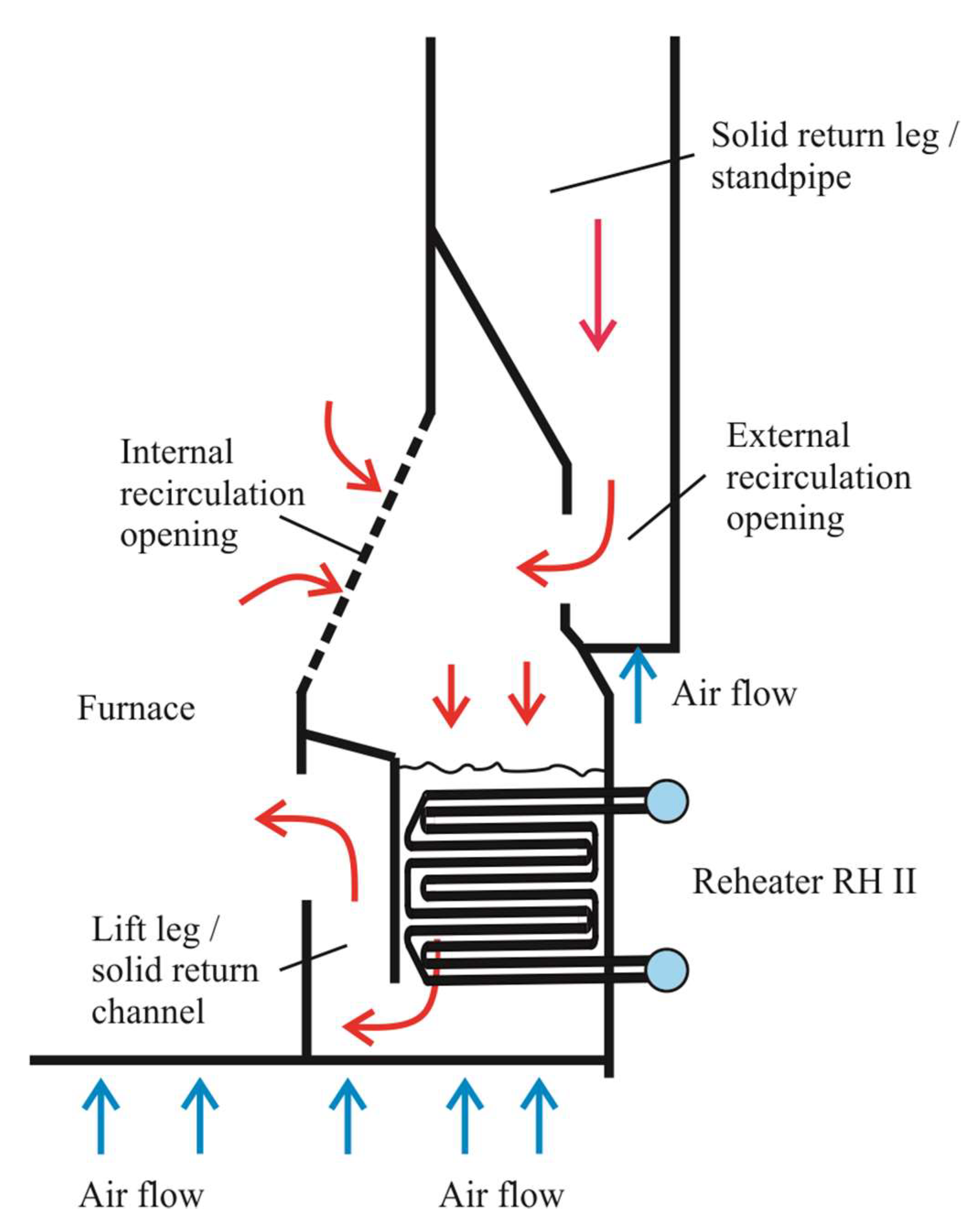
Figure 4 shows the layout of the fluidized bed heat exchanger. The entrained bed material from the furnace chamber is collected in the solids separator and then returned to the fluidized bed heat exchanger via the return leg (external circulation). The high gas-solid separators efficiency ensured sufficient solids flow to the FBHE for all experimental conditions listed in
Table 4. In the FBHE chamber, the circulating material provides heat for the high temperature reheater RH II. The cooled bed particles are returned to the bottom region of the CFB furnace through the solids return channel. Additionally, openings at the lower part of the furnace chamber provide access for bed particles within the furnace to enter the FBHE chamber (internal circulation). The internal circulation ensured sufficient bed particles directly flow to the heat exchanger chamber at low boiler loads as well. In the case of excessive bed material inside the FBHE chamber, a bypass system allows the solids to flow back to the furnace chamber through the overflow channel. The bed particles’ flow rate through the tube bundle versus through the overflow is affected by changing the amount of aeration airflow added to the lift leg. By controlling the bed particles’ flow rate through the chamber of the heat exchanger RH II, the heat absorption varied and at the same time provides the operational flexibility to control the furnace and superheat steam temperature. The fluidized bed heat exchanger has an independent air grid and air plenum.
In order to investigate the heat transfer behavior in a large-scale external heat exchanger with a horizontal smooth tube bundle, eight tests were performed under different bed particle sizes conditions. In the heat exchanger chamber, the bed material flow was perpendicular to the heating transfer surfaces. There, the heating surfaces in the form of a horizontal smooth tube bundle are arranged in the staggered array, as shown in
Figure 4 and
Figure 5.
The staggered tube arrangement was immersed in the dense-phase zone with the exception of the three rows of tubes from the top. The top tube bundle section is operated under splash zone conditions. The low height of the fluidized bed inside FBHE is a result of the high drainage constant for the heat transfer chamber. This situation is caused by the fact that the main fuel with a high level of ash content is burned within the combustion chamber of the CFB boiler during all examined conditions. Furthermore, the bed material (0.219 ≤
dp ≤ 0.246 mm) is collected through the solids separator at the high separator characteristic (99.45% <
ηcycl < 99.75%) during the tests. Moreover, previous work [
50] confirmed that the separator efficiency is not dependent upon ash content in the main fuel or the particle size distribution of the bed material.
In an external heat exchanger, heat transfer tubes are 51 mm in outside diameter and 7.1 mm in wall thickness. The heat transfer surface in the horizontal bundle is arranged in a staggered tube array with a relative horizontal pitch
ph/
dt of 1.35 and with a relative vertical pitch
pv/
dt of 2.19. The pitch-to-diameter ratio
pv/
dt for the horizontal smooth tubes in a bundle is allowed for a good mixing within the fluidized bed and also for the upward flow of bubbles between adjacent smooth tubes [
57]. Hence, for optimal heat transfer conditions in a fluidized bed heat exchanger, the relative diagonal pitch
pdiag/
dt equaled 2.70. In this heat transfer study, a permeability
dp/pmin for the considered tube bundle array varied between 0.003 and 0.004. More details on the geometry characteristics of the horizontal tube bundle used in the heat transfer modeling are summarized in
Table 5.
Selected construction data have not been presented due to commercial reasons. Nevertheless, the bottom row in an external heat exchanger is located about 500 mm above the air distributor (grid) in order to prevent irregular fluidization. On the other hand, the distance between the top row of high temperature reheater tubes and the arrow nozzles equaled 1.54 m.
5. Results and Discussions
The following section presents the predicted heat transfer data on important parameters in the design of fluidized bed heat exchangers. The procedure described in
Section 2 was used to estimate the average heat transfer coefficient for the considered reheater RH II. Furthermore, the experimental data from
Table 4 were used as an indispensable starting point to estimate the average heat transfer coefficient. The computed results are depicted in
Figure 6,
Figure 7,
Figure 8,
Figure 9,
Figure 10 and
Figure 11 for different values of
dp. The following results discussion correspond to Group B powders. The error bars shown in
Figure 7,
Figure 8 and
Figure 9 depict the relative error in determining the values of average heat transfer coefficients by the developed mechanistic heat transfer model. In fact, error bars give a better insight to the depicted heat transfer data and any divergences that took place. In selected graphs, the trend lines are the heat transfer data fittings. The correlations for predicting the heat transfer coefficient are developed and are based on heat transfer data presented in this section. Furthermore, the developed mechanistic heat transfer model is validated by experimental data in the operating regime of interest.
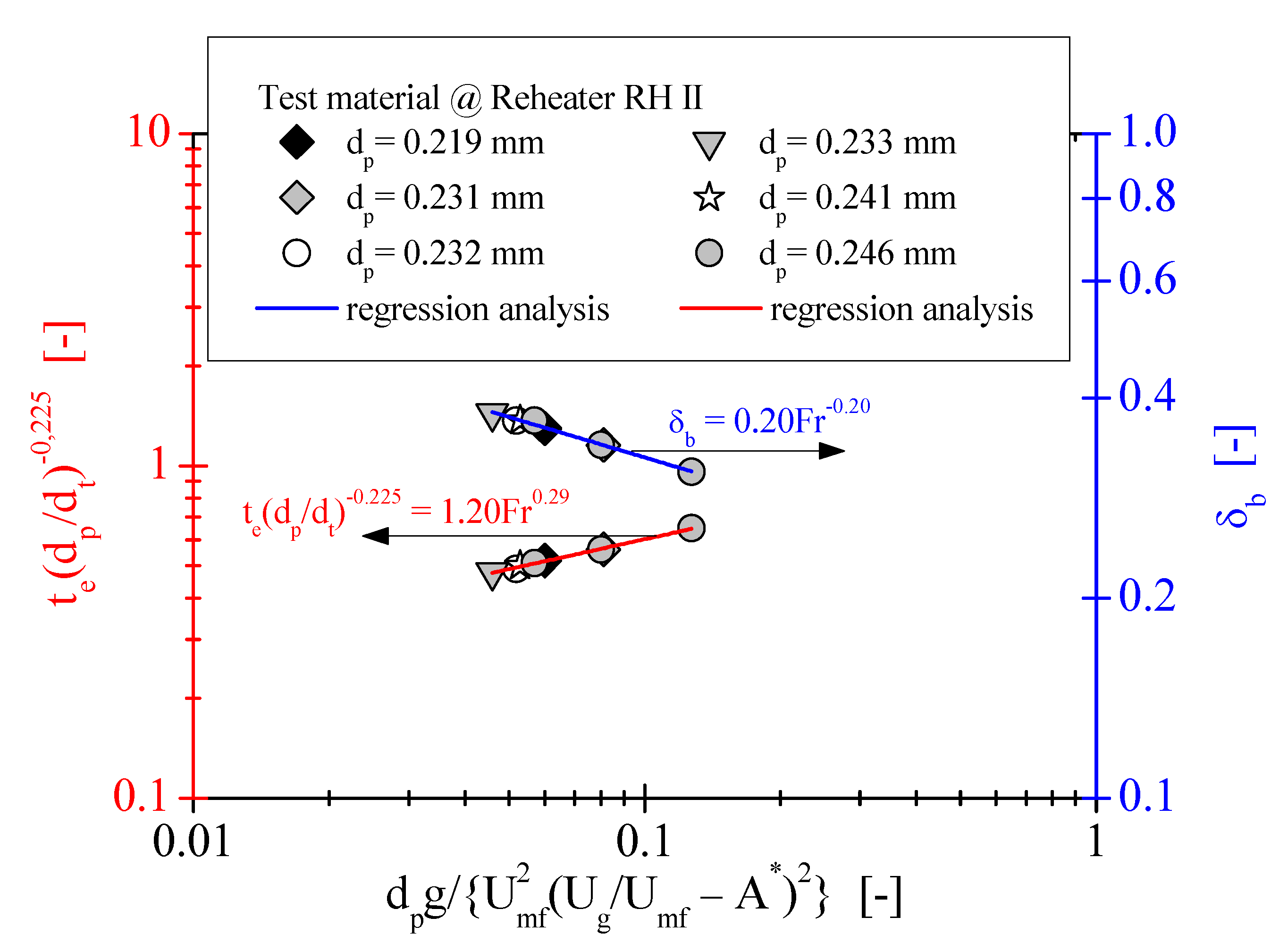
The variations of emulsion contacting time and also bubble fraction with the Froude number are depicted in
Figure 6. As exhibited in
Figure 6, the achievable values of emulsion contacting time
te as well as bubble frication
δb are in the ranges of 0.14 s–0.19 s and 0.31–0.38, respectively. The highest emulsion contacting time and the lowest bubble fraction are observed in the bed particle diameter of 0.246 mm (@
Ug = 0.14 m/s). Meanwhile, the lowest
te and the highest
δb recorded in the bed particle size equals 0.233 mm (@
Ug = 0.23 m/s). The reason for this observation is the fact that the bed particle replacement near the horizontal tube bundle strongly depends on the superficial gas velocity. The calculated results evidently show the linear variations of values for both the emulsion phase contacting time and the bubble fraction for the particle diameters of 0.219–0.246 mm. The calculated emulsion contacting time shows no fluctuation, but the monotonic increases with the increase in the Froude number. Meanwhile, the bubble fraction predicted from Equation (4) tends to decrease with the increase in the Froude number. In addition, the trends of the correlations for horizontal tube configuration have been confirmed experimentally through other scientists/authors [
29,
34].
The relationship of
te and
δb with the Froude number is somewhat involved inasmuch as it does not depend on the particle size, as is illustrated in
Figure 6. It resulted from
Figure 6 that the similarity in behavior of the bed particles is majorly dependent on fluidization material properties and also the local hydrodynamics around the submerged horizontal tube bundle, as well as the fluidization velocity. Nevertheless, for the six different particles, a certain regularity has been observed. The low value of emulsion contacting time corresponds to the high value of bubble fraction and vice versa. Thus, it can be concluded that the emulsion contacting time is inversely proportional to the bubble fraction. Hence, the interplay between the parameter
te and the parameter
δb is presented in one graph.
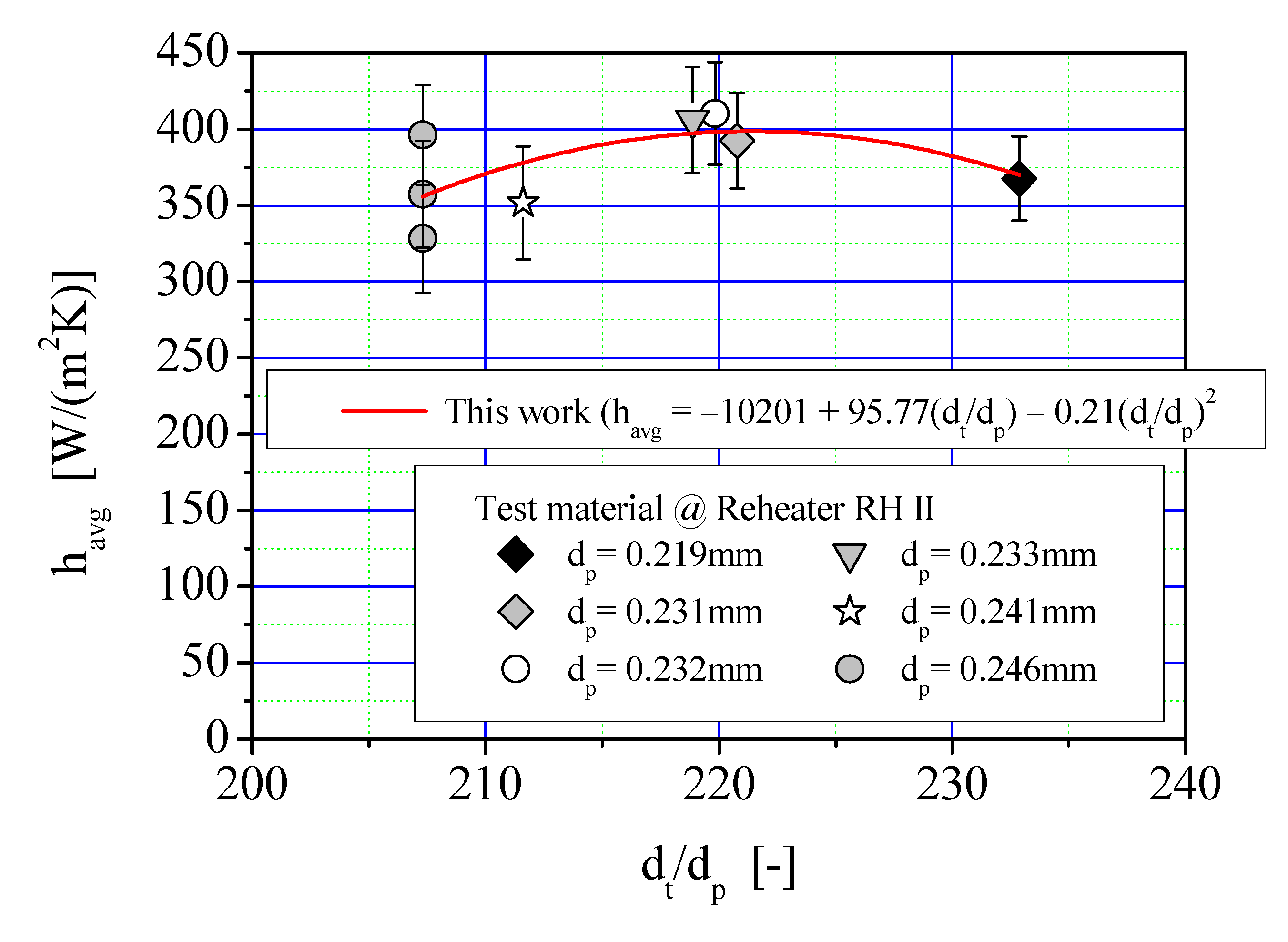
Figure 7 depicted the average heat transfer coefficient as a function of the Sauter mean particle diameter for a fluidized bed modeled by a mechanistic model based on the packet-renewal approach. As can be seen, the bed-to-tube heat transfer coefficient is increased slowly at the ratio
dt/
dp in the range of 207.3–219.8 and then proportionally is decreased at the
dt/
dp ratio of 220.8–232.9. This trend of heat transfer coefficient variation was not consistent with the observations made in the earlier works [
15,
27].
With reference to
Figure 7, it can be concluded that for a given ratio of
dt/dp the highest heat transfer rate is obtained when commercial FBHE was operated with bed particles size of 0.232 mm (@
dt/dp = 219.8). By the way, the lowest value of the average heat transfer coefficient (
havg = 328 W/(mK)) is obtained when an industrial fluidized bed system was operated with the bed particle diameter equal to 0.246 mm (@
dt/dp = 207.3). This seems to correlate with the quality of fluidization (i.e., emulsion contacting time and gas bubble dynamics), indicated by the superficial gas velocity. This problem will be discussed in more detail in a further part of the research paper (see
Figure 10). Nevertheless, it is worth noting here that the properties of the fluidizing gas have an essential impact on the heat transfer characteristics in a fluidized bed tubular heat exchanger.
It is visible from
Figure 7 that there is a large discrepancy in the values of the heat transfer coefficient. The possible reason for this discrepancy is a result of particle type. The fluidized bed particles with much the same emulsion heat capacity give a similar heat transfer rate. For bed particles with size from 0.231 to 0.233 mm and with the emulsion heat capacity equal to c.a. 0.962 kJ/(kgK), it is observed that the low variation in the values of bed-to-tube heat transfer coefficient (Δ
havg = 18 W/(m
2K)) in opposition to the bed particles diameter of 0.246 mm (Δ
havg = 68 W/(m
2K)). In addition, the predicted data show that the highest heat transfer rate is not observed when the fluidized bed heat exchanger is operated at a bed particle diameter of 0.219 mm (
ce = 0.949 kJ/(kgK)). Thus, it can be concluded that the way to increase the heat transfer coefficient is not to use the finest particles.
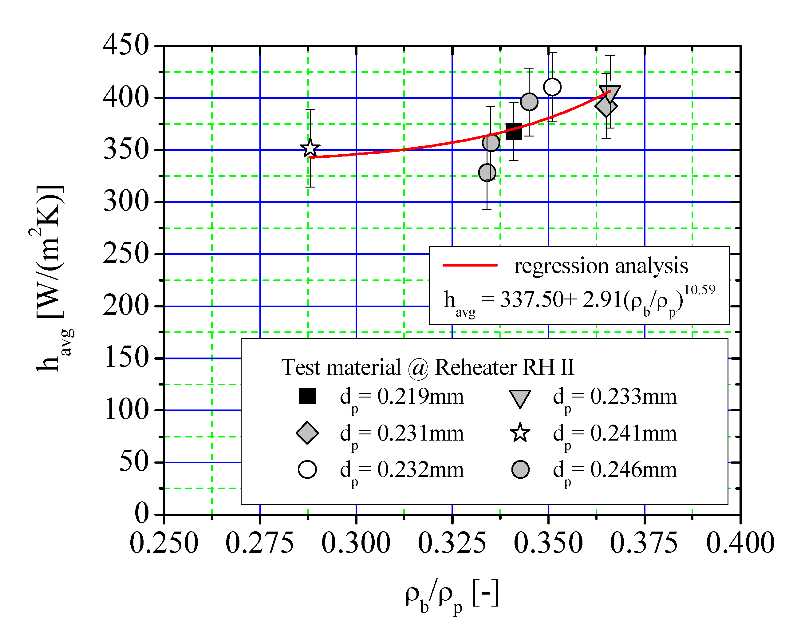
The predicted average bed-to-tube heat transfer coefficient of the six mean bed particle sizes as a function of normalized suspension density is shown in
Figure 8. The suspension density is derived from the measured pressure drop along the FBHE chamber and is calculated using the simple relation:
Here, g represents acceleration due to gravity, Δp refers to the pressure drop and Δz denotes the distance between pressure taps.
Values of suspension density are normalized by dividing each value for suspension density by the value of particle density pertained to the given test. Nevertheless, the suspension density data have been encrypted by the owner CFB unit and will not be reproduced in the present heat transfer study. In
Section 3, the overall range of the calculated suspension density values is listed in
Table 4.
As shown in
Figure 8, the average heat transfer coefficient obtained using Equation (5) varied between 328 and 410 W/(m
2K) for the examined conditions. The heat transfer rate gradually increases, however is exponential with an increasing suspension density, as is represented by the red curve. The variation of the bed-to-tube heat transfer coefficient with normalized suspension density as a bed hydrodynamics parameter is a result of the several times higher thermal conductivity of the emulsion phase in contrast to the thermal conductivity of the gas phase, for instance,
ke/
kg = 6.6 @
dp = 0.232 mm whether
ke/
kg = 5.5 @
dp = 0.241 mm. When the normalized suspension density is high enough (0.351 <
ρb/
ρp < 0.366), then the heat transfer surface is covered by the emulsion phase or packets and the augmentation heat transfer is achieved, unlike at the lower suspension density in the EHE chamber. Up to 0.288 or 0.334, the calculated heat transfer coefficient remains approximately constant
(Δ
h =5 W/(m
2K)). The Sauter mean particle diameter has little effect on the average heat transfer coefficient, with the exception of the heat transfer rate @
ρb/
ρp < 0.341. It should be noted that the highest scatter in the values of heat transfer coefficient was recorded for the mean particle diameter and equaled 0.246 mm. This can be explained by the fact that the bed particles at about the same diameter have different particle densities, as also indicated by the authors in their previous work [
27]. The predicted values of the average heat transfer coefficient are not uniquely dependent on the suspension density but are influenced by gas bubbles activity and emulsion phase/packets motions immediately near the horizontal tube bundle. The highest heat transfer rate is due to increased particulate loading together and gas bubble-induced circulation. In general, it was observed that at the Sauter mean particle diameter of 0.232 mm; the horizontal smooth tube bundle is exposed to a short contact time (
te = 0.15 s) with the emulsion phase and a high level of bubble fraction (i.e.,
δb = 0.37) in the fluidized bed. Meanwhile, at the lowest suspension density conditions (i.e.,
ρb/
ρp = 0.288 @
dp = 0.241 mm), the reheater tube bundle was operated with a lower replacement rate of packet particles by gas bubbles. This argument can be confirmed by the aforementioned ratio of
ke/
kg and the higher voidage of the emulsion phase (
εe = 0.79 and
hg/
havg = 0.2) during the performance test with a bed particle size of 0.241 mm. The share of gas convection in heat transfer mechanisms for other mean bed particle diameters was negligible (
hg/
havg = 0.01). The contributions of individual heat transfer mechanisms between the fluidized bed and the reheater tube surface are discussed in a further part of this work.
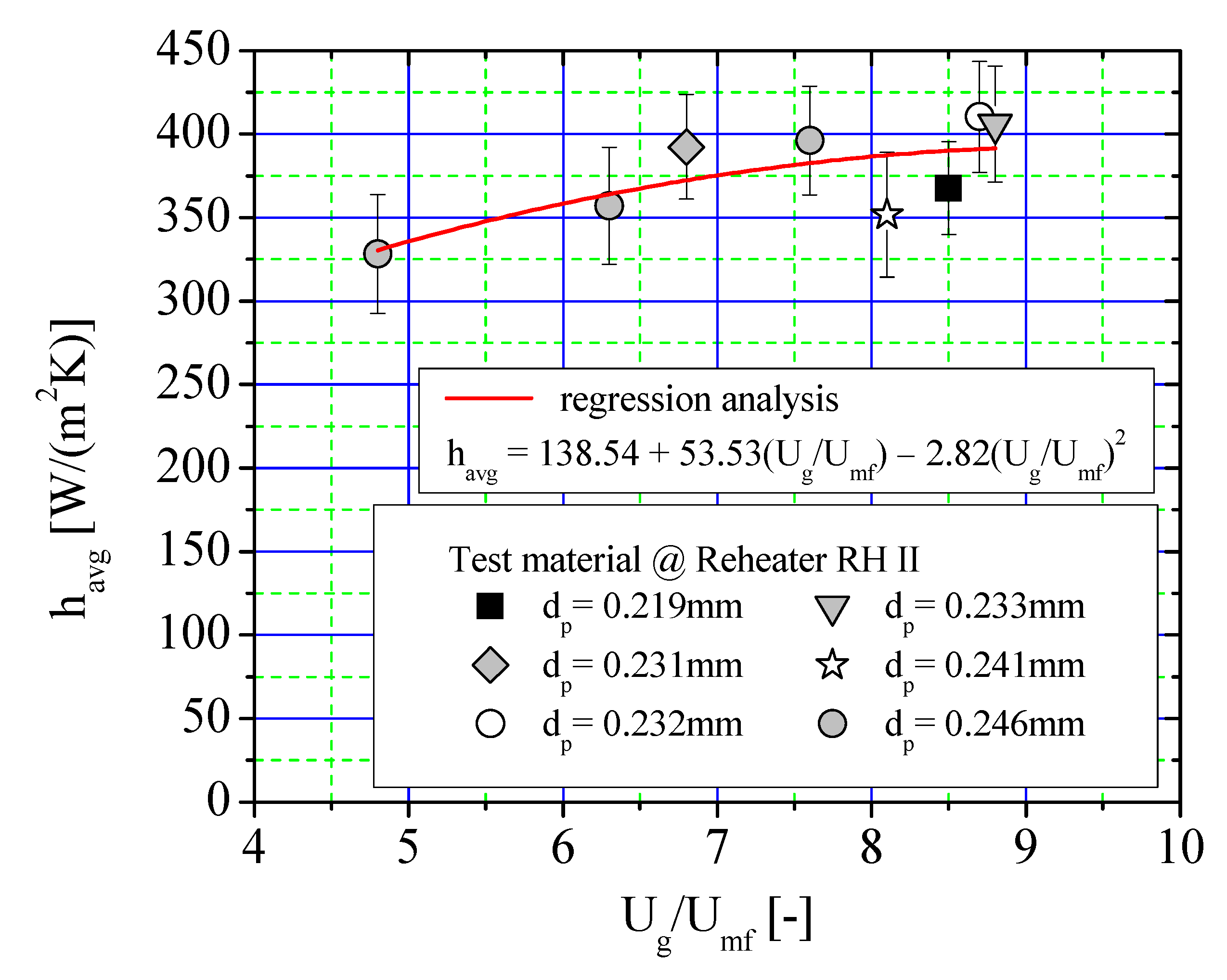
The influence of superficial gas velocity in terms of fluidization number,
N =
Ug/
Umf, on the estimated average heat transfer coefficient at different Sauter mean bed particle diameters is depicted in
Figure 9. Based on
Figure 9, there is an upward trend of increasing the average heat transfer data with an increase in the superficial gas velocity, except for the values of the average heat transfer coefficient at mean bed particle sizes of 0.241 and 0.219 mm (8.1 <
Ug/
Umf < 8.5). The predictions of this model represent the similar trend variation of average heat transfer coefficient with increasing superficial gas velocity, similar to the works of [
16,
17,
24,
34,
58,
59,
60,
61,
62,
63]. In
Figure 9, the red line represents the correlation equation obtained for the heat transfer data using a nonlinear regression in Origin 8 software [
64]. In this predicated correlation, the effect of the bed hydrodynamic parameters, such as superficial gas velocity and minimum fluidization velocity, has been implemented in this correlation. The regression data for the selected values of the bed-to-tube heat transfer coefficient are presented in
Figure 9. All examined bed particles show a polynomial increase in heat transfer above the minimum fluidization velocity. It is shown that the fluidization number has an essential impact on the average heat transfer coefficient. Nevertheless, the values of bed-to-tube heat transfer coefficient are increased at a very slow rate at the mean bed particle sizes of 0.232 and 0.233 mm, whereas the superficial gas velocity is varied between 0.21 and 0.23 m/s, respectively. These values of superficial gas velocity are observed at the optimal heat transfer conditions during all performance tests. Furthermore, the influence of superficial velocity on heat transfer rate can be negligible when
Ug/
Umf is sufficiently high.
The highest value of average heat transfer coefficient (havg max = 410.29 W/(m2K)) was recorded for a Sauter mean particle diameter equaling 0.232 mm. Furthermore, the heat transfer coefficient is lower when the external heat exchanger is operated with a bed particle size of 0.246 mm and a fluidization number lower than 6.8.
As can been seen in
Figure 9, with an increase in gas flow rate beyond the minimum fluidization conditions, the emulsion phase comes into contact with the horizontal smooth tube bundle. This is probably due to increased bed-to-tube surface contact dynamics that change significantly with gas flow rate and particle size inside an external heat exchanger. At the low fluidization number range from 4.8 to 6.3, the emulsion phase contacting time with the horizontal smooth tube bungle is varied between 0.17 and 0.19 s. At the same time, for
Ug/
Umf > 8.1, the higher values of average heat transfer coefficient were caused by shorter emulsion contacting time (0.14 s <
te < 0.15 s), contrary to the tests with the low level of superficial gas velocity. Thus, the heat transfer data indicated that the emulsion contact characteristics with reheater surface RH II play an essential role in the heat transfer rate. From the predicted heat transfer data, a resulted interplay between the emulsion phase or packets and gas bubble activity occurs. It is evident that a decrease in the gas bubble size leads to the increase of bubble frequency and a higher frequency of packet replacement in the vicinity of tubular surfaces. Which in turn leads to the higher values of the average heat transfer coefficient.
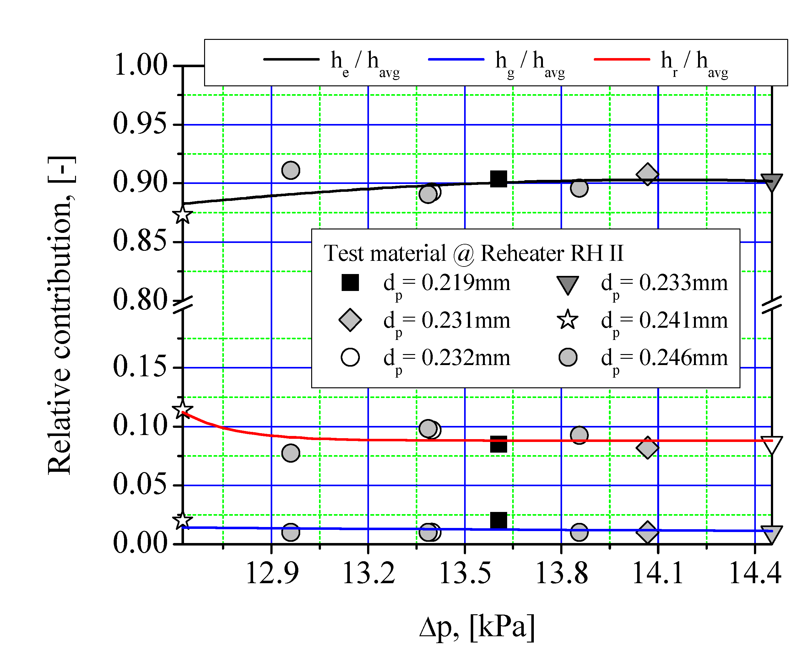
Figure 10 shows the relative contribution ratio of individual heat transfer mechanisms versus pressure drop. As shown in this figure, one dominant mechanism of heat transfer took place from fluidized bed particles towards the tube reheater. The convection heat transfer from particle packet (emulsion phase) as a single predominant heat transfer mechanism was varied in the range from 0.87 to 0.91 for wide operating conditions of the fluidized bed heat exchanger. The highest value of
he contributed to the average heat transfer coefficient was achieved at the pressure drop of 12.96 kPa for a mean bed particle size of 0.246 mm. The dominant role of the emulsion phase component in heat transfer mechanisms resulted from high solids suspension density (not less than 793 kg/m
3) in the considered fluidized conditions. For fine bed particles, the estimated contribution of convection heat transfer from the emulsion phase increased slowly until the pressure drop of 13.4 kPa and then with further increases in the pressure drop remained at the constant level. By the way, higher
he/havg was caused by the high intensity of bed material movement in the vicinity of tube bundle as a result of enough gas fluidization velocity and very short particle residence time on the reheater tube surface RH II.
The contribution of gas convection mode in heat transfer mechanisms in the case of all considered mean bed particle diameters was negligible (0.01 <
hg/
havg < 0.02). The contributions of
hg/havg for all mean bed particle diameters differed little from one another (i.e.,
hg/havg = ± 0.01). In all particle sizes, it was found that the predicted trend of
hg/havg values was independent of the pressure drop. Particularly, the low contribution of gas convection to the average bed-to-horizontal tube heat transfer coefficient resulted from the high bed voidage (0.63 ≤
ε ≤ 0.71) and the low fractional heat transfer surface area, which was exposed to gas bubbles (0.12 ≤
fB ≤ 0.15). In the present heat transfer study, the tube surface area fraction covered by bubbles was estimated by the following equation [
65]:
where symbols used in Equation (15) are explained in the aforementioned Equation (1).
The contribution of radiation to the average heat transfer coefficient varied from 0.11 to 0.07, with an increase in pressure drop in the range of 12.62–14.45 kPa. The values of the
hr/
havg ratio confirmed that thermal radiation is not an important heat transfer mechanism for the operating bed temperature ranges of 918–1094 K. As can be seen in
Figure 10, the ratio of radiation to total heat transfer is changed by an asymptotic at the pressure drop in the range of 12.62–13.31 kPa. The major reason for the low radiation contribution to total heat transfer was that the high solids concentration occurred in the fluidized bed heat exchanger during the performed tests. The radiative component will be playing a key role at high temperature under diluted phase conditions.
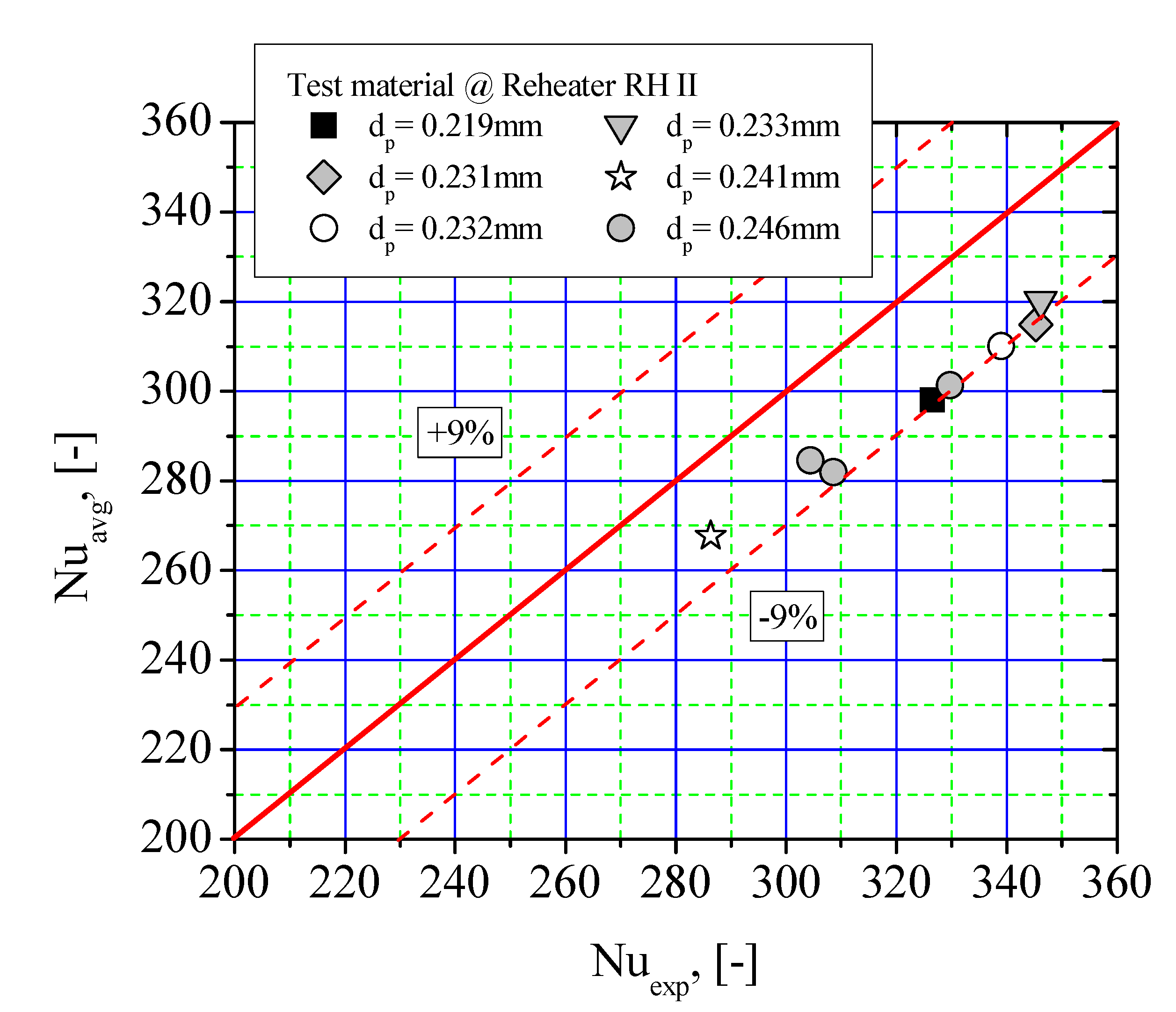
In order to validate the theoretical relationship of the average heat transfer coefficient (Equation (5)) proposed in the present study, the findings coming from performance tests are employed to check the usefulness of the mechanistic heat transfer model. The comparative analysis was conducted between the predicted Nusselt number
Nuavg and the experimental Nusselt number
Nuexp, and it is shown in
Figure 11. The following relationship is used to calculate the experimental data,
Nuexp.
where,
Ah means heat transfer surface of the reheater RH II,
cp refers to steam heat capacity,
represent steam mass flow,
Tin and
Tout denote steam temperature at the inlet and outlet, respectively. Other denotations used in Equation (16) are explained in Equation (1) and also in
Table 2 and
Table 4. In the above calculation,
Nuexp is the employed value of steam parameters (mass flow, temperature at the inlet and the outlet), bed temperature and wall temperature, which are obtained on the basis of the measurements carried out during the performance tests. The small divergence between the predicted Nusselt number and the experimental Nusselt number results from a few cases. The higher experimental data are due to enhanced mobility of bed particles and bubbles dynamics adjacent to the reheater tube surface. The probable reason was that the thickness of the “gas film” around the heat transfer surface of the reheater RH II, which is of the order of magnitude of a bed particles’ diameter. For bed particles with sizes from 0.219 to 0.246 mm, the effective conductivity of loosely packed bed particles was almost six times as high as the conductivity of the gas phase. In the present heat transfer study, the ratio of
ke/kg varied from 5.00 to 6.11. As for the flow parameter, such as gas bubble dynamics in the vicinity of the heat transfer surface, it is dependent on all possible operating and system parameters. It should be noted that some of the physical parameters of the emulsion phase are not available with ease for industrial fluidized bed heat exchangers. Therefore, the authors have made a great effort to ensure accurately reproduced thermal-flow conditions inside the Intrex
tm chamber with the reheater tube bundle immersed in a dense fluidized bed.
Good agreement between the calculated Nusselt number and the experimental Nusselt number was obtained when the fluidized bed heat exchanger was operated at the bed particle with sizes in the range of 0.219 to 0.246 mm. As shown in
Figure 11, all calculated Nusselt numbers by the mechanistic model were predicted within 9% of the experimental Nusselt number values with a mean relative deviation of 5.86%. This agreement demonstrated the validity of the proposed heat transfer model in predicting the average bed-to-tube heat transfer coefficient in a large-scale FBHE. Hence, the developed mechanistic heat transfer model is also applicable here.


