1. Introduction
Steel bars are the primary metallurgical components that are widely used in various fields of the industrial manufacturing. Similar to most steel products, these steel bars are manufactured by a rolling process. Such metalworking usually does not provide the required mechanical and technological properties of the final product. Therefore, the bars require additional heat treatment [
1]. Heat treatment operations have a significant impact on energy consumption, production efficiency, and pollutants emissions to the natural environment, and obviously they have an impact on the quality of the final product. Hence, the heat treatment process has to be optimized. This is often performed by computational analysis of the appropriate numerical models [
2,
3,
4]. The thermal properties of a heated element are important parameters for these analytical models.
To ensure the most efficient use of a furnace chamber, the treated bars are usually heated in the form of cylindrical bundles. As shown in
Figure 1, the bundle of round bars has a porous structure, which makes the effective thermal conductivity
kef its basic thermal property [
5]. Contrary to the thermal conductivity of homogeneous substances, this parameter is not a material property.
The effective thermal conductivity of the bar bundle is a function of the complex heat transfer mechanisms related to conduction and radiation and can be defined as the sum of two components, the essential thermal conductivity
kes and the radiation thermal conductivity
krd (Equation (1)) [
6,
7]:
The coefficient
kes represents the heat transferred by conduction in the bundle, while
krd relates to the heat transferred by radiation. Thus, one of the thermal properties of the bar bundle is
krd and its value can be determined analytically. Most often the concept of a unit cell is used for this purpose. This approach uses periodically repeated elements of idealized geometry. In spherical or cylindrical particle systems, the
krd is generally calculated as the quotient of the radiation exchange factor
FR, the Stefan–Boltzmann constant
σ, particle diameter
dp, and the third power of the mean absolute temperature of the medium
T (Equation (2)) [
8,
9]:
Despite the simple form of the Equation (2), this approach has a serious limitation, which arises from the difficulties in determining
FR. This factor cannot be easily calculated, which leads to significant discrepancies in the results obtained by researchers [
10,
11,
12,
13]. There are several correlations that have been developed for packed bed structures. However, these correlations are not suitable for a packed bed of bars as they are developed for materials consisting of spherical particles. In contrast, in the bed of bars, individual elements (particles) have a cylindrical shape. As a result, the geometry of the surfaces closing the space of radiation heat transfer is different in both cases, which results from various values of view factors. The possibility of using various correlations from literature reports for determining the
FR factor for modeling radiation heat transfer in the packed beds of steel bars was analyzed in [
14]. Five different computational models were analyzed in detail: Cheng and Churchill [
10], Vortmeyer [
11], Wakao and Wato [
12], Argo and Smith [
13], and Kasparek and Vortmeyer [
15]. As a result of the calculations, it was shown that these five models gave significantly different
FR in the range from 0.5 to 1.05, while for the bed of steel bars, the
FR was in the range from 0.4 to 0.6. On the basis of these calculations, it was found that the models from studies reported in the literature do not give correct results when the analyzed medium is the bundle of bars. This paper presents an innovative method of determining the
FR radiation exchange factor in the bundle of steel round bars.
2. Materials and Methods
In the proposed approach, the radiation exchange factor
FR for the bundle of steel round bars is calculated from Equation (3), which results from the rearranging Equations (1) and (2):
The
kef and
kes coefficients, which are required to calculate the
FR factor, were initially determined on the basis of the analysis of thermal resistances. This method is based on the analogy of the phenomena of electrical and thermal conduction, which arise from the similar mathematical notation of two laws: Ohm and Fourier [
16]. At the first stage of calculations, a geometric model of the medium considered was developed and analyzed. It was assumed that the medium can be reduced to a flat bed of bars with a staggered arrangement. The repeatable rectangular part of this model is shown in
Figure 2a. Based on this geometrical part, equations for the vertical heat flow described by the heat flux vector
q (
Figure 2b) were worked out.
The cell includes fragments of two layers of bars (top layer
1 and bottom layer
2) and is divided into three sections following sections that are parallel to the vector
q: a central section (
II) and two side sections (
I, III), which are identical to each other. To define the cell geometry, the bar diameter
dp and the width of the gap between the bars from layer
lgp are applied. Based on these two parameters, the cell height
δK (Equation (4)) and width of the side sections
lp (Equation (5)) are defined:
The next step of the analysis is the identification of all heat transfer mechanisms occurring within the cell. The heat transfer through the bundle of bars can be modeled as a combined effect of the following mechanisms: (i) conduction through individual bars, (ii) conduction in gas-filled voids, (iii) contact conduction between adjacent bars, and (iv) thermal radiation between the surfaces of the bars. Each of these mechanisms can be quantified by an appropriate thermal resistance. Referring this problem to the investigated cell, the resistances in the side sections can be distinguished as follows:
RI 2s and
RIII 2s for the conduction in the bars from the bottom layer,
RI 2g and
RIII 2g for the conduction in gas cavity,
Rct for contact conduction between adjacent bars,
RI rd and
RIII rd for thermal radiation, and
RI 1s and
RIII 2s for the conduction in the parts of bar from the top layer. In turn, one can distinguish the following resistances for the central section:
RII g for the conduction in gas cavity,
RII rd for the thermal radiation, and
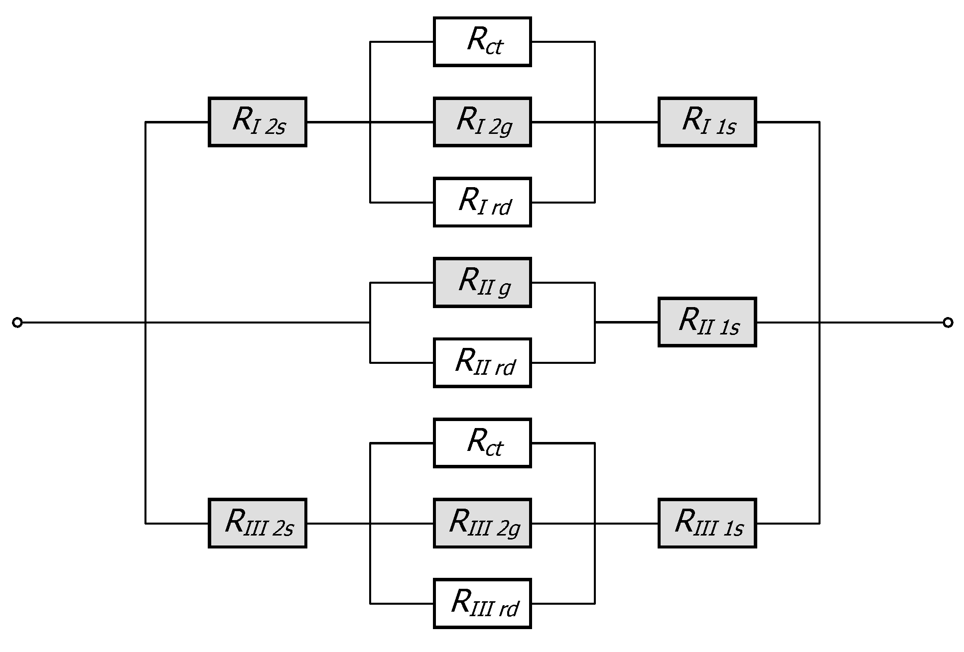
RII 1s for the conduction in the fragment of the bar at the top layer. The total, thermal resistance of the elementary cell
Rto is calculated as the resultant resistance of the series- and parallel-connected resistances noted above (Equation (6)). The equivalent system of these resistances is shown in
Figure 3.
where
The method of determining the thermal conduction resistances for all elements in the cell (these resistances in
Figure 3 are shown in gray) is described in detail in [
17]. When calculating these resistances, one should take into account that the bar thermal conductivity
ks and the gas thermal conductivity
kg vary with temperature change. In the case analyzed, it was assumed that the material of the bars is low-carbon steel S 235JRH with a maximum carbon content of 0.2% [
18], whereas the gas phase is ambient air. Thermal conductivity
ks of the assumed grade of steel and thermal conductivity of air are identified with Equations (10) and (11) [
19]:
The
ks and
kg coefficients were calculated according to Equations (10) and (11) for the temperatures selected and are presented in
Table 1.
The thermal contact resistance
Rct between adjacent bars is calculated from an empirical equation (Equation (12)) [
20]:
where
In the case of thermal radiation, the resistance
Rrd for the entire cell is calculated with Equation (16). The space of radiation heat transfer in this system is enclosed by four surfaces:
A1,
AI,
Agp, and
AIII. The thermal resistance for radiation
Rrd in this system is calculated from the radiosity balance method [
16,
21]. After rearranging, the equation for this resistance is in the form given in Equation (16) [
14]:
where
Xrd is a dimensionless coefficient with its value depending on the bar emissivity
ε and its shape, together with the relative position of the surfaces that closed the space of radiation exchange;
T is the absolute mean temperature of all surfaces. For the arrangement of the surfaces in the cell considered, coefficient
Xrd is described by Equation (17) [
22]:
Radiation resistances
RI rd,
RII rd, and
RIII rd related to the individual sections are described by Equations (18) and (19):
The effective thermal conductivity
kef of the cell is defined by the equation of thermal conduction resistance in the flat, homogeneous layer (Equation (20)) [
16]:
In turn, the
kes coefficient is calculated under the assumption that there is no radiation heat transfer within the cell (Equation (21)). Adjusted total thermal resistance
Rto a, used in this case, is calculated according to Equation (22). The equivalent electric analog system of the thermal resistances, taken for consideration in this case, is shown in
Figure 4.
where
and
According to this methodology, the calculations of the FR factor were realized in the following steps: (i) first, the effective thermal conductivity kef is determined, (ii) next, the essential thermal conductivity kes is calculated, and (iii) last, the radiation exchange factor FR is calculated from Equation (3).
The calculations included three bar diameters (10, 20, and 30 mm), five emissivity values (0.5, 0.6, 0.7, 0.8, and 0.9), and three bundle porosities. The bundle porosity in the geometric model considered is a function of the gap width lgp. The lgp value is defined as a multiple of the bar diameter; three cases were considered: 0, 0.2 dp, and 0.4 dp, which correspond to the following porosities: 0.091, 0.145, and 0.214. The calculations were performed in the temperature range 200 to 800 °C.
3. Results and Discussion
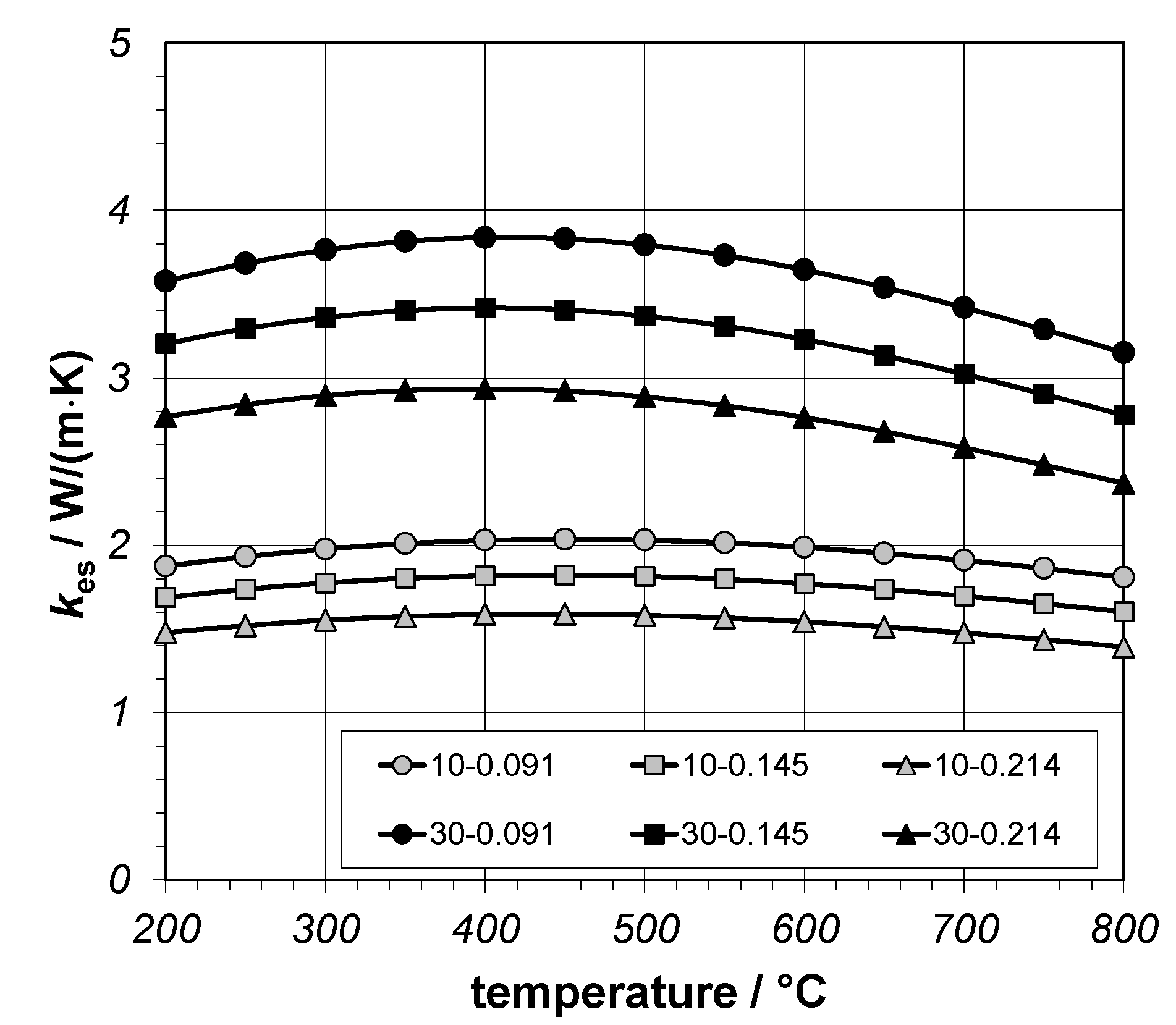
First, the values of the essential thermal conductivity
kes were presented (
Figure 5) in order to analyze the results of the calculations. These results refer to two bar diameters (10 and 30 mm) and all porosities considered. In the chart (
Figure 5), the reference table refers to the bar diameter and porosities used. As can be seen, the
kes coefficient increases with increase in the bar diameter and decreases with increase in bundle porosity. In any case, the maximum value occurs at approximately 400 °C. The values obtained for all cases are in the range 1.4 to 3.9 W/(m·K).
The increase in
kes with increase of the bar diameter is caused by the changes in thermal contact resistance
Rct. According to Equations (12)–(15), the resistance
Rct decreases with increasing bar diameter, which was determined from experimental studies on bars bed samples [
19]. In these tests, samples were made of bars with diameters of 10, 20, 30, and 40 mm. It is well known that thermal contact resistance depends on the contact area between the adjacent elements [
23,
24]. For adjacent bars, the contact area is greater when the bars are straighter. It was found that the smaller the diameter of the bars, the less straight they are, and thus, the samples have a smaller contact area and finally, the resistance
Rct increases.
The decrease of the kes coefficient with increase of cavity is caused by heat transfer between successive layers of bars. Heat is transferred here by conduction in the air cavity and contact conduction. When the cavity width is changed, the contact surface between the bars does not change significantly; hence, the contact conduction does not change either. However, increase in the cavity increases the area of conduction in air. This mechanism of heat transfer is much less efficient than contact conduction. As a result, a decrease in contact conduction is observed in relation to overall conduction in air, which contributes to a decrease in the value of kes.
The last question: why is there a maximum of kes at 400 °C? The change in thermal contact resistance Rct is responsible for this change, which is described by Equation (12), obtained from extensive experimental research. The minimum of this resistance appears at temperature of approximately 400 °C. This is due to a number of bar properties that determine the intensity of contact conduction, which include thermal conductivity, Young’s modulus E, Poisson’s ratio ν, and the surface microhardness Hc. These factors depend on temperature and are mutually connected. For this reason, at the present stage of research, it is difficult to clearly explain how individual factors affect the changes in Rct and thus also on kes as a function of temperature.
Figure 6 shows the radiation thermal conductivity
krd. These results relate to a bundle with a porosity of 0.091, two bar diameters (10 and 30 mm), and three emissivities (0.5, 0.7, and 0.9). It is clearly visible that the coefficient
krd increases with the temperature, emissivity, and bar diameter; the maximum values for all cases are in the range 0.7 to 4.4 W/(m·K).
The next two figures show the changes in the radiation exchange factor
FR as a function of temperature.
Figure 7 relates to a 10 mm bar bundle and
Figure 8 to a 30 mm bar bundle. As can be seen in all cases, the
FR decreases slightly as a function of temperature, and the amount of this decrease depends on the diameter of the bars. The same effect is observed for the bundle porosity, while
FR increases significantly with the bar emissivity. The
FR values, depending on temperature, bar diameter, bar emissivity, and bundle porosity, are presented in
Table 2.
In the next stage of the analysis, radiation exchange factors averaged for the entire temperature range were estimated for each computational case. The
FR values obtained in this way, depending on emissivity and bar diameter, are shown in
Figure 9.
Figure 9a relates to the bundle with a porosity of 0.091, while
Figure 9b relates to the bundle with porosity of 0.214. Note that regardless of porosity, radiation exchange factor depends slightly on the bar diameter. Therefore, it was required to reaverage
FR taking into account the bar diameter. The final averaged
FR values obtained in this way, both as a function of bar emissivity and the bundle porosity, are shown in
Figure 10. As referenced, parameter
FR for all porosities changes almost linearly as a function of the bar emissivity. Therefore, in order to generalize the results obtained, regression functions were determined using Equation (25):
The
B1 and
B2 coefficients from Equation (25) corresponding to the individual bundle porosities are presented in
Table 3.
As established, both B
1 and B
2 change almost linearly as a function of the bundle porosity
φ, which can be described by Equations (26) and (27):
Based on Equations (25)–(27), it is possible to present a generalized relationship describing changes in
FR parameter both as a function of the bar emissivity and bundle porosity (Equation (28)):
Based on Equation (28), it is possible to formulate one simple algebraic relationship to determine the radiation thermal conductivity
krd of the bar bundle (Equation 29):
As a result of the Equation (29), some simplifications have been made concerning averaging over the bar diameters and temperatures. Therefore, the value of the coefficient
krd calculated using this relationship is characterized by a certain inaccuracy. This inaccuracy can be described by the relative percentage discrepancy (RPD) with Equation (30):
where
krd-ex is obtained from the thermal resistance’s analysis (exact approach) and
krd-sp is calculated with Equation (29).
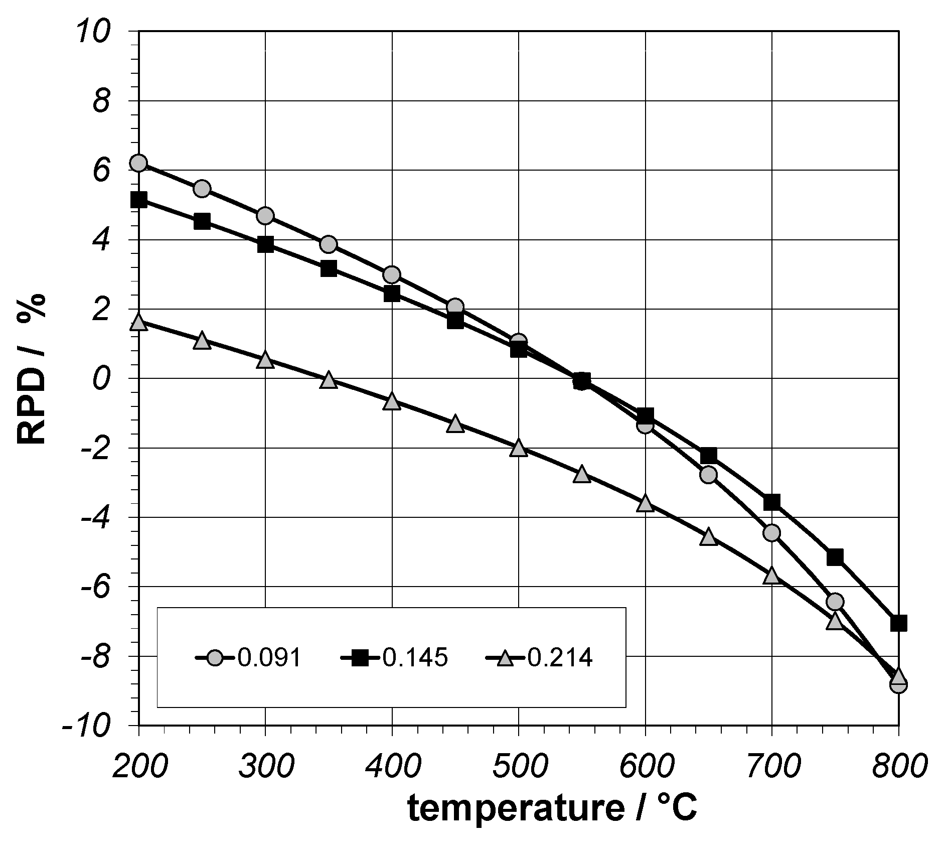
Figure 11 shows the results of the RPD parameter depending on the temperature and porosity for a 30 mm bar bundle and 0.8 emissivity. As can be seen, the largest changes in RPD were recorded for the lowest porosity. In this case, the analyzed parameter changed with the temperature increases from 6% to −9%. From the industrial practice point of view, the inaccuracy of calculations of the radiation thermal conductivity at this level is acceptable. Importantly, after averaging over the entire temperature range, the RPD value was only 0.2%. Thus, Equation (19) can be used to determine the radiative thermal conductivity as one of the basic thermal properties of the bar bundle.
4. Conclusions
The article presents an innovative methodology for determining the radiation exchange factor for steel bar bundles. The analysis performed resulted in formulation of a new equation that determines the parameter FR correlated with the emissivity of the bars and the porosity of a bundle. Results show that the FR depends on the bar diameter, emissivity, and bundle porosity, and it is in the range 0.19 to 0.69. The main advantage of this methodology is its simplicity; hence, potential errors can be quickly identified and removed. It also allows calculations of the krd coefficient. Other methods for determining these parameters are based on the analysis of thermal resistance and require several sophisticated numerical calculations. It needs to be highlighted that Equation (28) is limited in terms of the material porosity. The maximum porosity of the bundle for which the equation can be used is 0.22. This limitation applies to the geometry of the elementary cell, which was used to analyze the thermal resistance in the medium considered.
The radiation heat transfer for surface to surface condition can be solved with the aid of CFD analysis. However, in order to perform such research, one must have appropriate commercial CFD software. In contrast, building our own code for CFD solution requires high skills in both programming (usually in C, C+), mesh generating, and solving partial differential equations. Additionally, the CFD techniques also require specialist knowledge and skills, which are laborious and time-consuming (long calculation times). Conversely, the model presented by the authors in the form of one simple algebraic equation allows for fast and reliable calculations as these calculations are based on simple correlations. Summarizing, the simple method proposed, which does not require CFD analysis, provides reliable results; hence, this is the main innovation of this study.


