Article

Instability Control of Roadway Surrounding Rock in Close-Distance Coal Seam Groups under Repeated Mining

1
College of Mining, Guizhou University, Guiyang 550025, China
2
Key Laboratory of Mining Disaster Prevention and Control, Qingdao 266590, China
3
School of Engineering, University of Warwick, Coventry CV4 7AL, UK
4
College of Energy and Mining Engineering, Shandong University of Science and Technology, Qingdao 266590, China
*
Authors to whom correspondence should be addressed.
Energies 2021, 14(16), 5193; https://doi.org/10.3390/en14165193
Submission received: 13 July 2021 / Revised: 17 August 2021 / Accepted: 18 August 2021 / Published: 22 August 2021
(This article belongs to the Special Issue Rock Burst Disasters in Coal Mines)

Abstract

:
In order to solve the problems of roadway stability and easy instability under repeated mining of close-distance coal seam groups, the mechanism and control technology of surrounding rock instability under repeated mining were studied via indoor testing, field testing, physical similarity simulation experiment, and numerical simulation. The results show that the surrounding rock of roadway has low strength, low bearing capacity, and poor self-stabilization ability, and it is vulnerable to engineering disturbances and fragmentation. Affected by the disturbance under repeated mining, the roadway surrounding rock cracks are developed and the sensitivity is strong, and it is prone to large-scale loose and destroyed. The location of the roadway is unreasonable, and the maximum principal stress of the roadway is 3.1 times of the minimum principal stress, which is quite different. Thus, under a large horizontal stress, the surrounding rock undergoes long-range expansion deformation. On the basis of this research, the direction and emphasis of stability control of roadway surrounding rock under repeated mining of coal seam groups in close-distance are shown. A repair scheme (i.e., long bolt + high-strength anchor cable + U-shaped steel + grouting) is proposed, and reduces the risk of roadway instability.

1. Introduction

Downward mining is the top-down mining between coal seams, and it is generally used in close-distance coal seam groups. Due to the disturbance of upper coal seam mining, the roof of the roadway is destroyed before the lower coal seam is mining, resulting in changes in the roof structure [1,2,3] and stress environment of the lower coal seam mining area [4,5]. In addition, the roadway surrounding rock is disturbed and destroyed repeatedly while mining the lower coal seam, which can easily lead to the instability and serious destruction of the roadway surrounding rock [6,7]. At present, the processes of mining and excavating have become unsmooth for most coal mines, the roadway support technology is unfeasible, there is a certain degree of convergence in the vertical and horizontal directions of the roadway [8], and significant roadway maintenance is required in the later stage of working face mining [9,10], which greatly affects the speed, safety, and efficiency of roadway excavation. The deformation and destruction of the roadway surrounding rock is more prominent when mining a close-distance coal seam groups, especially for the excavation of soft rock roadways, the floor heave and sidewalls often move inward [11,12]. Therefore, studying the stability control technology of the surrounding rock of the roadway under repeated mining of the close-distance coal seam groups has important theoretical and practical significance for its safe and efficient mining.
The following are the results of the main studies on the surrounding rock instability and control of the roadway associated with the downward mining of the close-distance coal seam groups. Some scholars have used UDEC to simulate the surrounding rock deformation characteristics of roadways at different intervals and internal staggered distances [13,14]. Some scholars also use numerical simulation methods with strength reduction method to analyze roof support and roadway stability in multi-coal mining [15]. Under normal circumstances, if two coal seams are very close together, the influence of adjacent coal seam mining on the roadway cannot be ignored [16]. FLAC3D is used for numerical simulation, and the influence range of stress superimposition will be formed above the roadway. The affected area of the roadway in the lower coal seam can be divided into four areas [17]. In order to analyze the deformation law of the surrounding rock of the roadway in the combined mining of coal seams at the close-distance, the FLAC2D is used to simulate the stress influence range of the working face, and the anchor dynamometer is used to measure the roadway deformation and verify the simulation results [18]. Aiming at the influence of coal pillars left over after mining of the upper coal seam on the surrounding rock structure and stress of the roadway in the lower coal seam, Wang et al. used UDEC numerical simulation to study the failure laws of the surrounding rock in multiple-seam mining roadway [19]. Petr Waclawik et al. arranged five monitoring probes to accurately obtain the rock mass stress and strain state and its changes during the mining of the Upper Silesian Coal Basin [20]. To address the roof fall and floor heave of working face E12505 in the Cuijiazhai coal mine, the instability mechanism of a mining roadway in the lower coal seam was discussed. Professor Fang proposed that the size of the protective coal pillar of the roadway should be 20 m based on the deformation characteristics of surrounding rock under different pillar widths, and the stability of the roadway can be improved by strengthening the roadway support [21]. Some scholars have improved the anchoring performance of rock by studying bolt-grout [22]. According to the change in the interval between coal seams and based on the principle of zonal support and source control (i.e., the use of asymmetric support source control according to the change in the force source form of the roadway and the use of zoning support according to the characteristics of the destroyed roof and the construction difficulty), a support technology with a bolt and cable as the main support and a U-shaped shed as the auxiliary support is proposed. The reliability of the technology is verified by field monitoring [23]. Some scholars have established similar models of close-distance coal seam mining to study the critical conditions of the peak energy surge induced by the pillars in the upper seam during lower seam mining to determine a reasonable location for the mining roadway of the working face in the lower seam [24]. Under normal circumstances, the coal pillars left in the upper coal seam mining will produce stress concentration in the lower coal seam mining roadway. Numerical simulation studies have shown that the close-distance coal seam mining without pillars can effectively control the roadway stress concentration [25]. In addition, due to the existence of coal pillar in the upper coal seam goaf, the lower coal seam roadway is prone to stress concentration. Reasonable adjustment of the support state and the use of π-shaped steel and anchor cable support can well control the surrounding rock deformation of the roadway [26].
Summarizing the above research, much has been revealed regarding the instability laws of the roadway surrounding rock during the mining of close-distance coal seam groups [27,28,29]. However, most of the above studies focus on mining areas in Shanxi province, Inner Mongolia province, and Poland, Australia, India, Thailand, Upper Silesian Coal Basin and other countries and regions or similar provinces that have thick coal seams, and the structure of the roof formed after mining is thus different from that in the Guizhou mining area. In addition, the coal seam is particular, and the distribution characteristics of the principal stress vary [30]. Therefore, it is necessary to take a mine in Guizhou as an example. This article will comprehensively use indoor testing, physical similarity simulation based on digital image correlation (DIC) system monitoring, numerical simulation and field testing are combined, and the results will complement each other and be verified by comparison. Further study the instability mechanism of the surrounding rock of the roadway based on the mining of the coal seam groups at a close-distance, and propose the corresponding surrounding rock control technology at the same time.

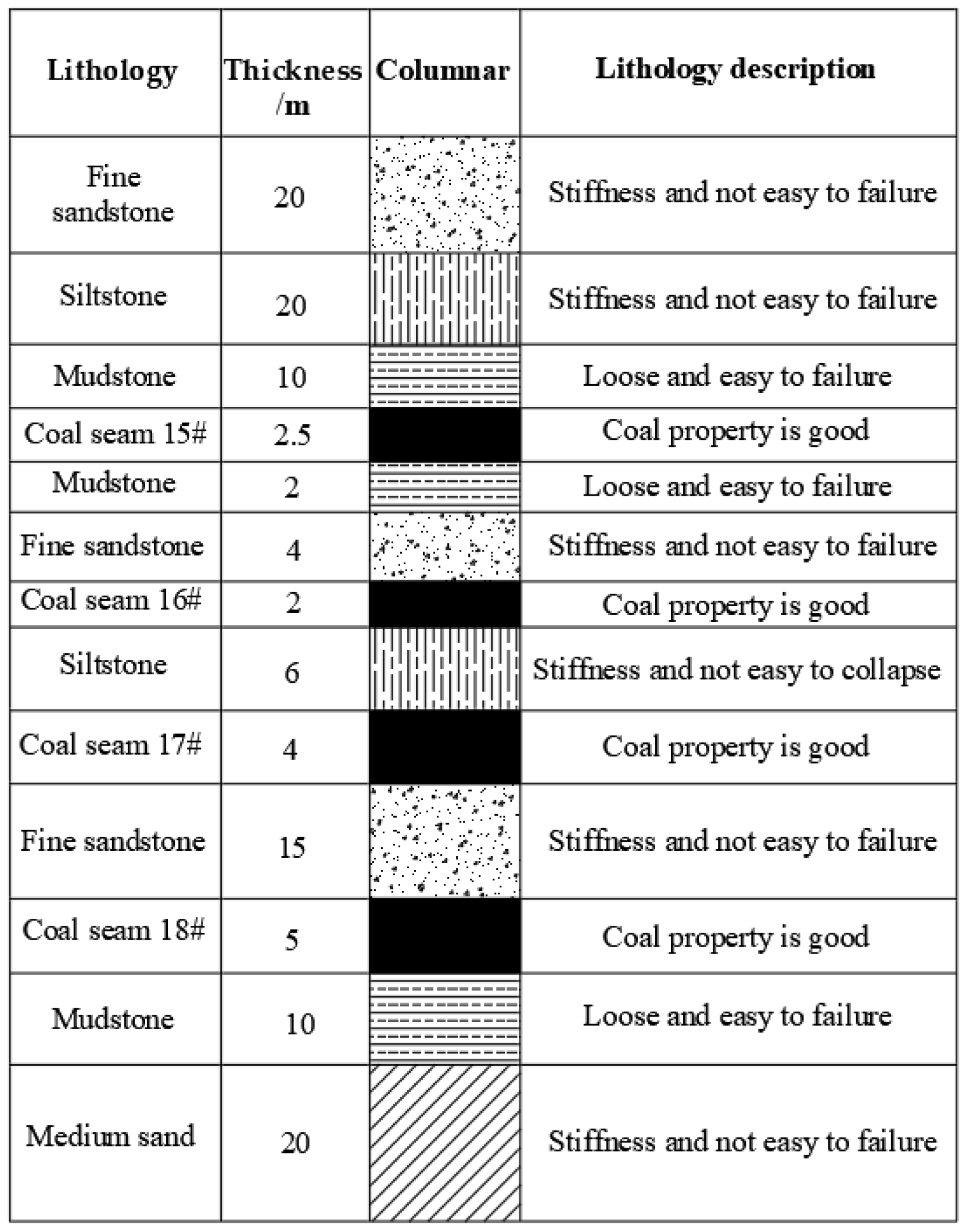
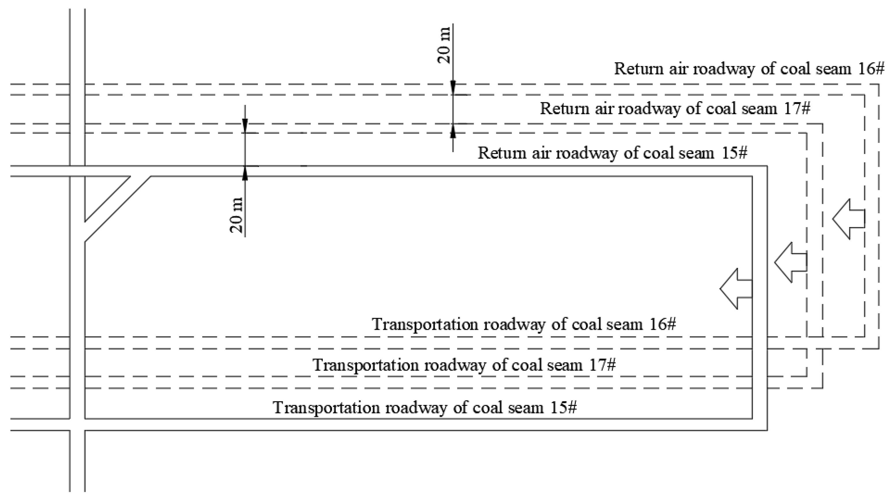
2. Engineering Survey

The mine is located in the Pan Jiang in Guizhou. The geological structures are complex with widely distributed faults and folds. Workable coal seams include coal seams #15, #16, #17, and #18, and the average thicknesses of these seams were 2.5, 2, 4, and 5 m, respectively [31]. Adjacent seams are the coal seams with small distance between them, the distance between coal seams #15 and #16 is 6.0 m, the distance between coal seams #16 and #17 is 4–8 m, and the distance between coal seams #17 and #18 is 15 m [31]. Therefore, coal seams mining in this mine can be classified as close-distance coal seam mining (as shown in Figure 1, the vertical section of the coal seams).
At present, coal seams 15# and 16# have been mined, and coal seam 17# is being mined, 17,101 working face is the first mining face of the coal seam 17#, with a mining depth of 500 m. It adopts comprehensive mechanized large mining height and one-time full-height receding mining. The length of working face is 120 m, and the length of advance is 1000 m. The inclination angle of the coal seam is relatively small, and it is a nearly horizontal coal seam. The spatial layer relationship between coal seam 17# 17,101 working face layout and coal seams 15# and 16# is shown in Figure 2. The 17,101 working face roadway is separated from the coal seams 15# and 16# working face roadway by 20 m in the horizontal direction. In addition, between the roadway and the working face, there is a 10 m-length coal pillar for roadway protection. The roadway was a curved-wall-top-arch section with a width of 5600 mm and a height of 3800 mm; the arch height is 2800 mm and the rib height is 1000 mm. Bolts 21.6 mm in diameter and 2500 mm in length were used for roof and rib support. Roof and rib bolts were installed with a spacing of 1200 × 1200 mm. In some local areas, anchor cables 21.6 mm in diameter and 6000 mm in length were used for reinforcement. The roof and floor strata are mostly mudstone and siltstone in this mine. Due to repeated mining in coal seams #15 and #16, during the mining of coal seam #17 [31], the mining roadway was seriously deformed and destroyed, and significant roadway repairs are required, which restricts the safe and rapid advance of the working face and affects the mining schedule.
The serious deformation of the mining roadway in the working face was photographed, as shown in Figure 3. The roof of the mining roadway has a large amount of subsidence, the coal walls on both sides have moved closer, and manual repairs are repeated, and there are risks such as roof leakage and roof fall.
Through a field investigation of the roadway deformation and failure characteristics of 17,101 working face, it is concluded that the mining roadway has the following deformation characteristics under the repeated mining of close-distance coal seam groups.
(1) The surrounding rock of the roadway undergoes significant deformation over a long duration. The roadway roof has an obvious shear fracture zone caused by horizontal extrusion and obvious expansion deformation. Due to the stress concentration of the coal pillars left while coal seams #15 and #16 were being mined, the surrounding rock deformation of the roadway is significant and occurs over a long period from the roadway excavation stage to the mining stage of the working face.
(2) The surrounding rock of the roadway is subjected to great pressure, and the U-shaped steel undergoes significant deformation and distortion. The coal pillar side of the roadway collapsed completely in a large area, the expansion of the solid coal side of the roadway was obvious, and the bulging volume of the roadway rib was large. The roadway ribs are more deformed than the roof and floor, indicating that the horizontal stress of the roadway is large.
(3) The surrounding rock of the roadway is relatively soft, fragmented, and its integrity is poor. Furthermore, the anchorage performance of the bolts and cables are suboptimal, the breakage and failure of anchor bolts and cables occur in many places, and the tearing of metal mesh is common.
According to the analysis of the deformation and failure characteristics of the roadway, the main factors affecting the deformation and failure of the roadway are the strength of the surrounding rock, the development of cracks in the surrounding rock, the stress distribution of the surrounding rock, and the support effect of the roadway.

3. Analysis of Roadway Surrounding Rock Instability

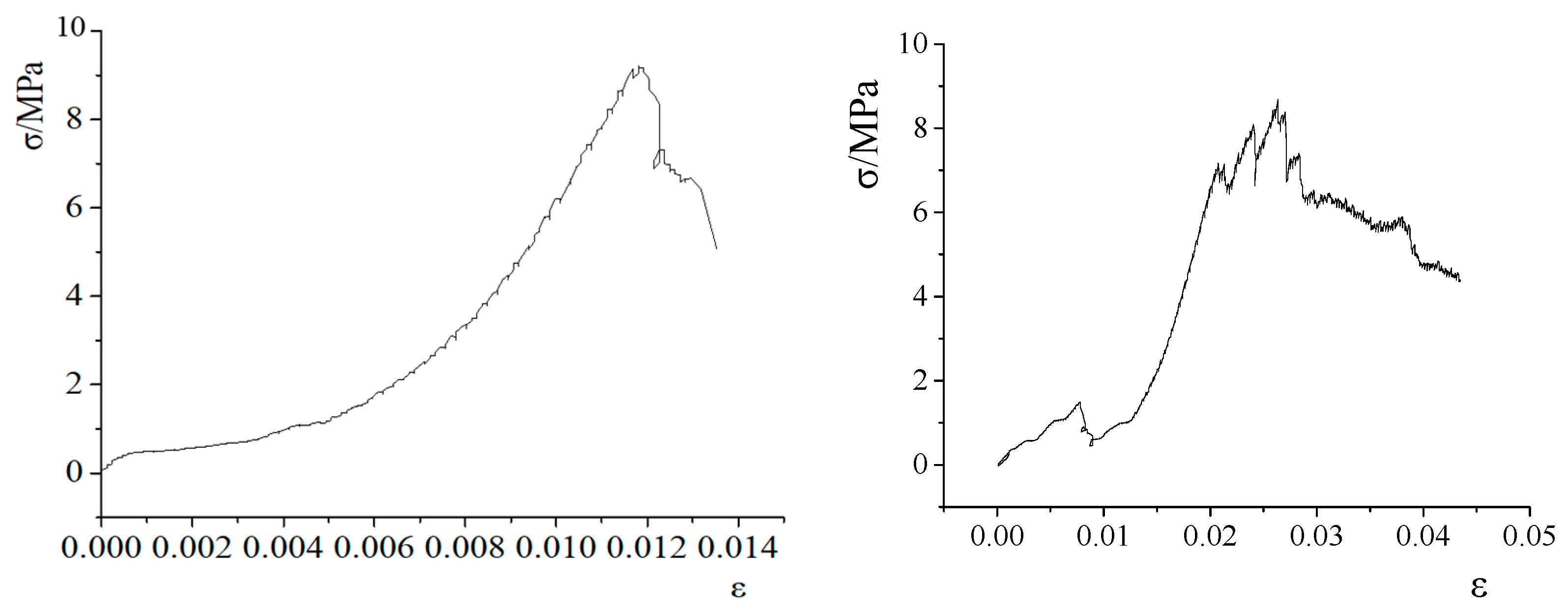
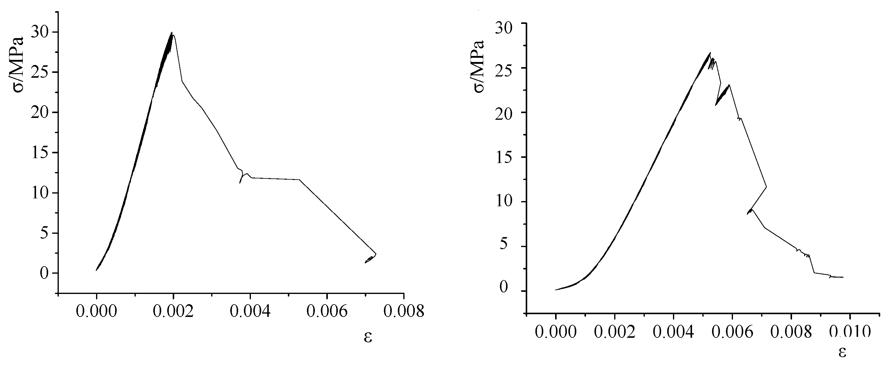
3.1. Rock Mass Strength Test of the Roadway Roof

The rock mass strength is the intrinsic factor affecting the stability of the roadway surrounding rock. To obtain the strength, deformation and the failure characteristics of the roof rock mass under uniaxial compression, rock cores are taken from the deformation and failure section of the roadway and tested on a rock mechanics testing machine [32]. The stress–strain curves of mudstone and siltstone specimens under uniaxial compression are shown in Figure 4 and Figure 5, respectively.
As seen from Figure 4, the axial strain of the two mudstone specimens are less than 3% before failure, and the failure mode is brittle failure. The yield stage is relatively short, and the two mudstone specimens will be destroyed quickly when the stress exceeds its strength limit. The residual strength is very low after failure, and there is almost no bearing capacity. The failure strengths of the two rock samples are 9.5 MPa and 8.5 MPa, respectively. The average failure strength is 9 MPa, and thus, the specimens are classified as soft rock.
It can be seen from Figure 5 that the stress–strain curve of the siltstone specimens is not smooth, indicating that there are many cracks in the specimens, and the failure mode of the two siltstone specimens is tension failure. The axial strains of the two specimens are 0.002 and 0.005; these values signify brittle failure. The failure strengths of the two specimens are 30 MPa and 28 MPa, respectively. The average failure strength is 29 MPa, and thus, indicates that the strength of the siltstone is relatively low.
From the uniaxial compressive strength testing of the mudstone and siltstone, it can be seen that the roadway surrounding rock has low strength and a small bearing capacity and is prone to fracture under the action of higher stress, which is also an inherent factor of the roadway surrounding rock instability.

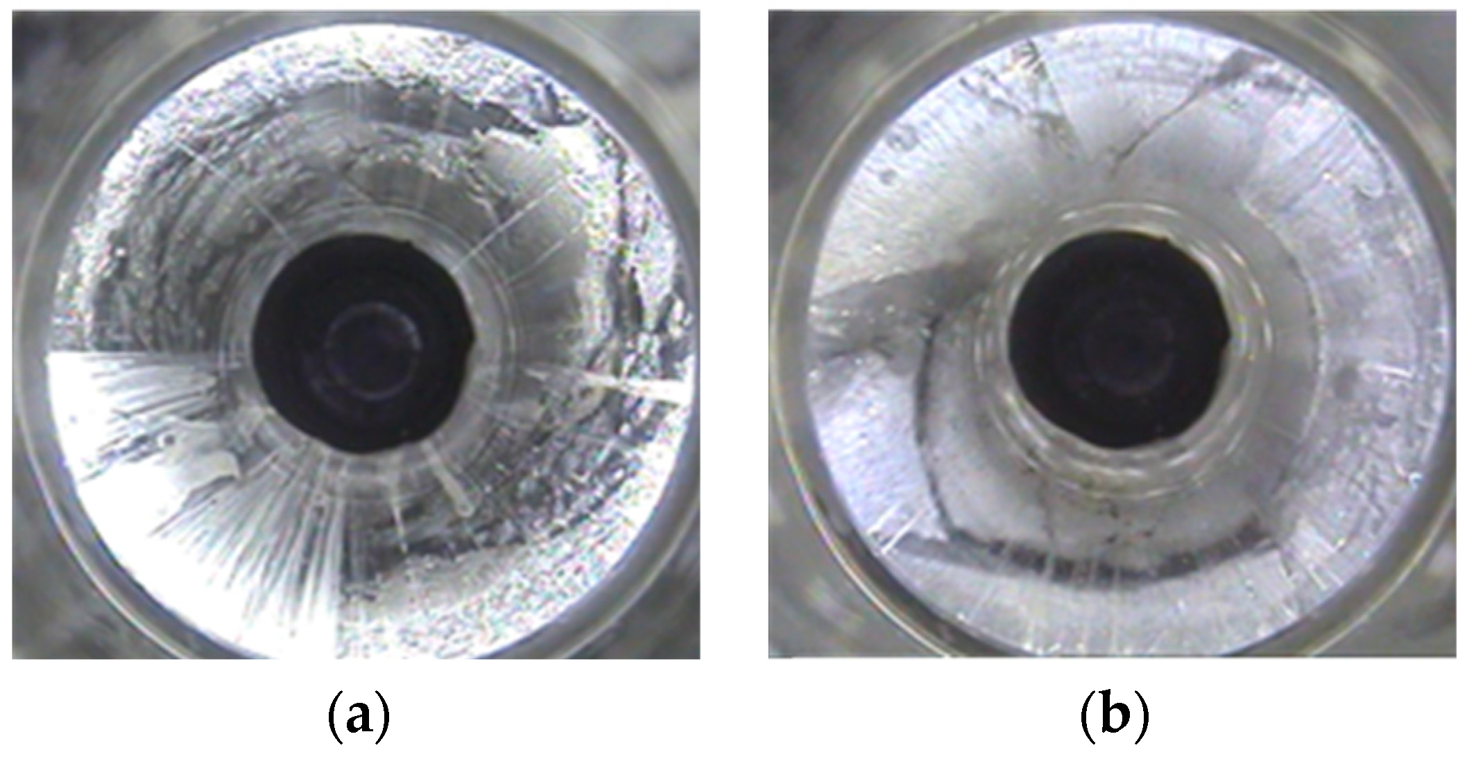
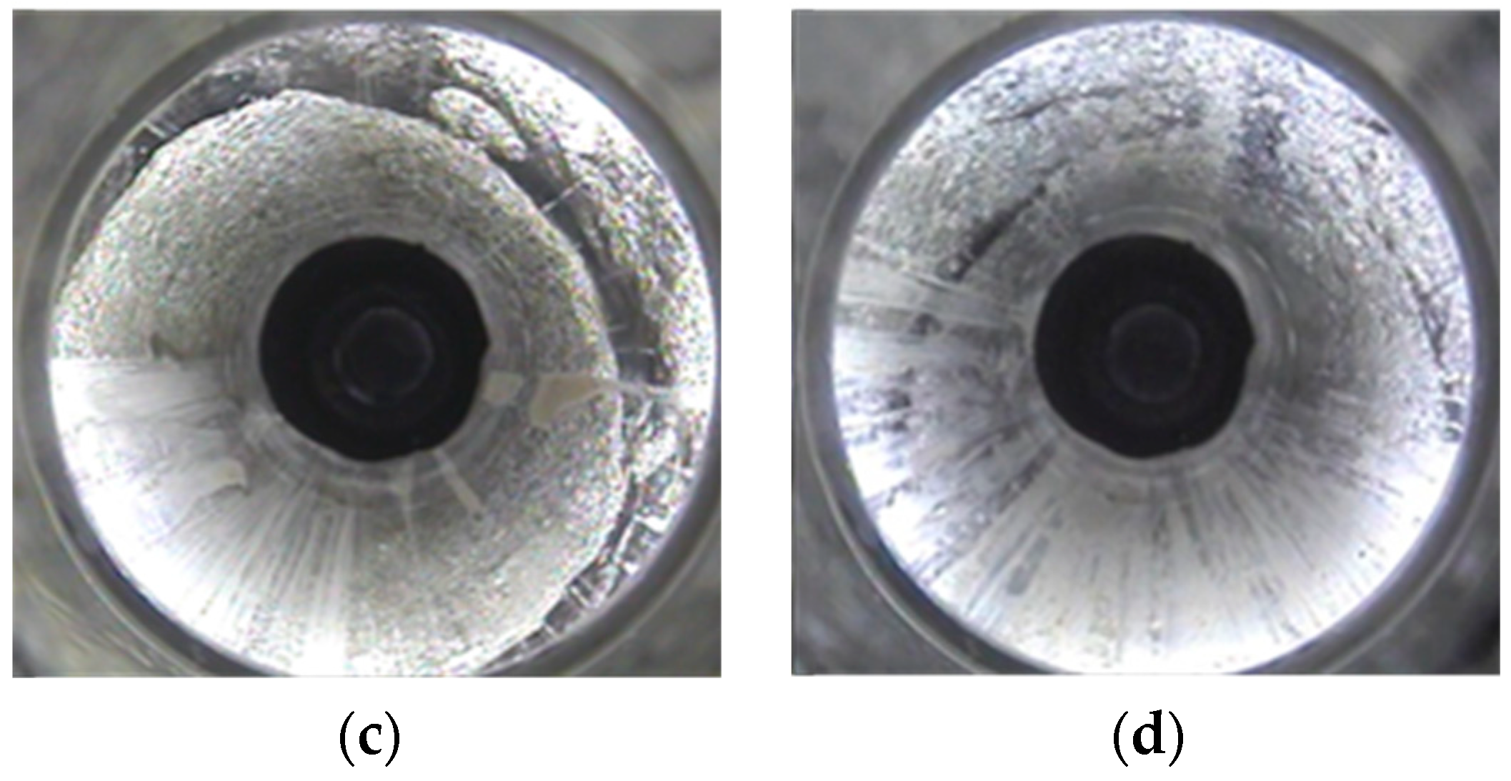
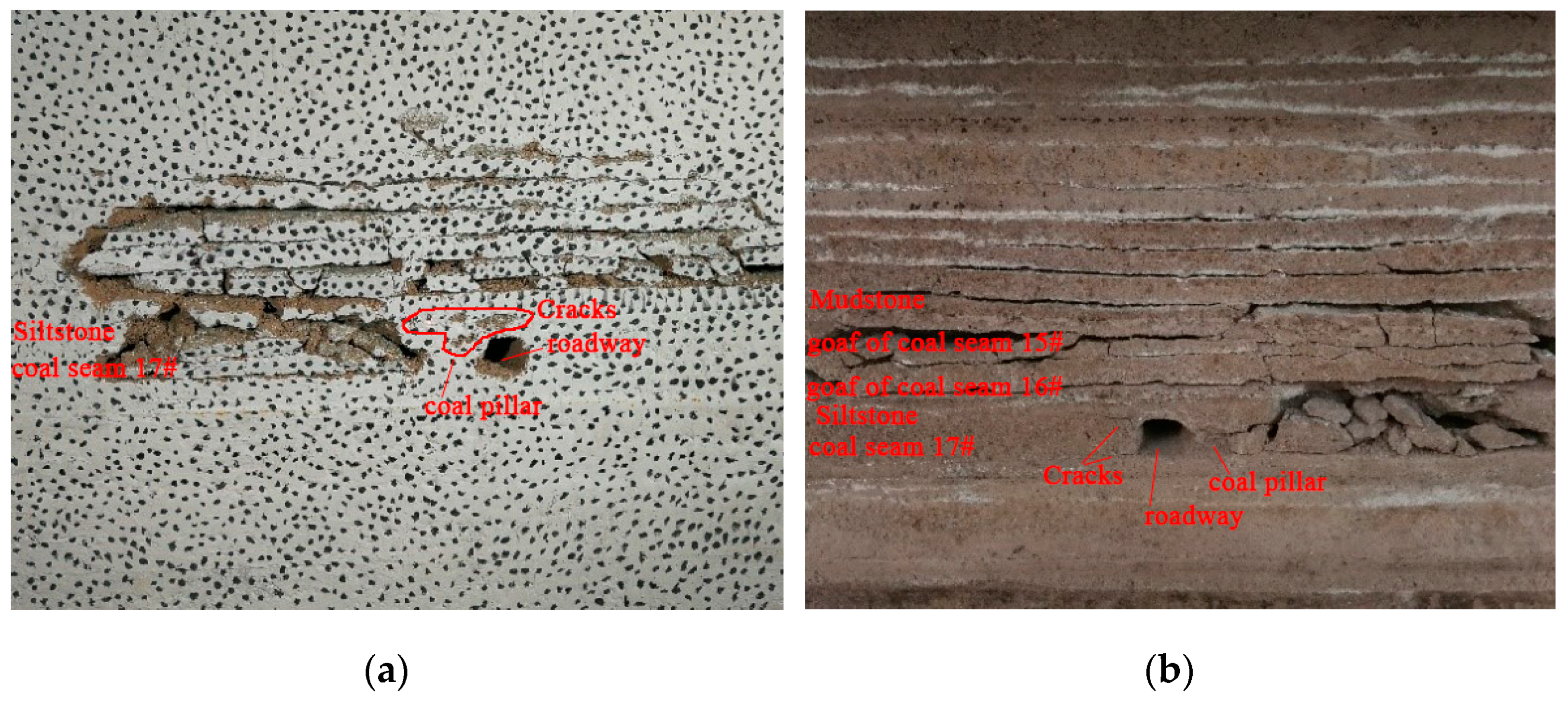
3.2. Borehole Observation of Loose Rock Surrounding the Roadway

The cracks development and distribution characteristics are major factors affecting the stability of the surrounding rock. To obtain the development law of the roof cracks in a roadway, a borehole camera is used to observe roof cracks development. In order to accurately determine the surrounding rock conditions of the roadway, the boreholes construction points are arranged as far as possible in locations where the production situation is basically stable, so that the measured development of the cracks in the surrounding rock of the borehole is universal and can represent the general situation of the surrounding rock of the roadway. In order to facilitate the observation and the observation results can reflect the actual conditions of the surrounding rock of the roadway, specific boreholes construction requirements have been formulated:
(1) In order to ensure that the borehole spy instrument completes the observation smoothly, the diameter of the borehole should be Φ50~Φ95 mm, the length of the borehole should ensure that the basic conditions of the overlying rock formation can be observed, and the inclination of the borehole shall be subject to the convenience of construction.
(2) The location of the boreholes is selected at the place where the roof of the roadway and the coal wall are complete.
(3) During drilling construction, as the distance between the coal seams is close to 6 m, the vertical depth of the boreholes to the roof should not be too long, but it should be no less than 4 m.
According to observations, the distribution of roof cracks at a horizontal distance of 45.6 m from the working face is the most representative. The observation results are shown in Figure 6.
From Figure 6, it can be seen that the rock mass located 0–0.6 m above the roof of the roadway is relatively fragmented, and longitudinal cracks are developed. The rock mass located at 0.6–2.8 m contains many types of cracks, such as longitudinal cracks, transverse cracks, and cross cracks, and they are relatively developed. The area at 2.8 m mostly consists of annular cracks, but local fragmentation also occurs. Annular cracks and longitudinal cracks develop at 3.4–4 m on the roof of the roadway, and microcracks develop from 4–5.6 m.
Therefore, through the above analysis, it can be concluded that the surrounding rock cracks of the roadway are relatively developed, and the rock mass strength decreases under the influence of repeated mining disturbances. Under a higher stress, the roadway surrounding rock can be destroyed, and the surrounding rock will undergo deformation, fracture and fragmentation in a short time, thus forming large-scale fragmentation.

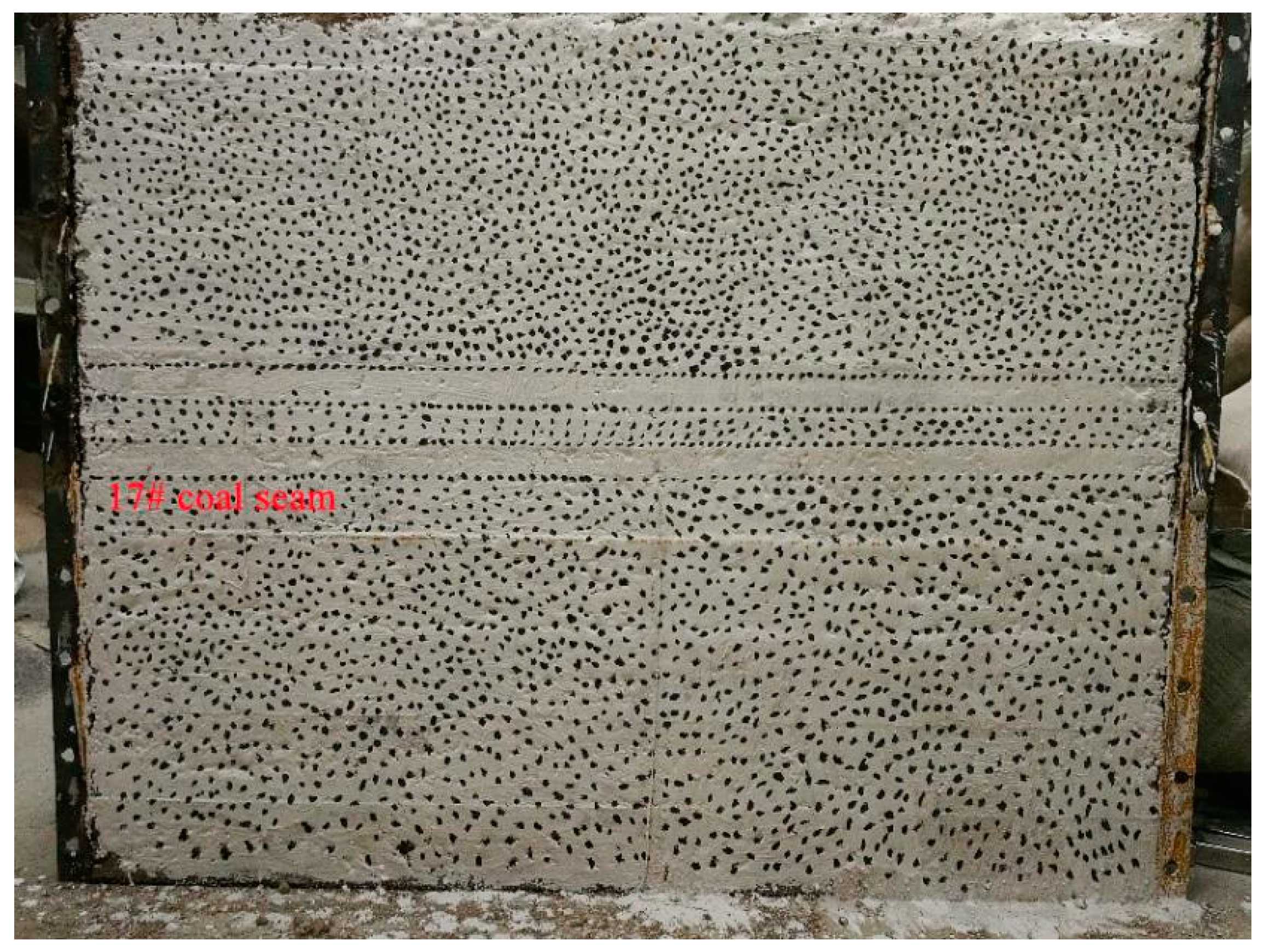
3.3. Displacement and Failure of Surrounding Rock of Roadway Based on Similar Simulation Experiment

In order to explore the displacement of the roadway surrounding rock under repeated mining, the physical similarity simulation experiment combined with the digital image correlation (DIC) system is adopted, after the upper coal seams are mined, when the coal seam 17# is being mined, the displacement and failure of the roadway surrounding rock under the repeated mining are analyzed.

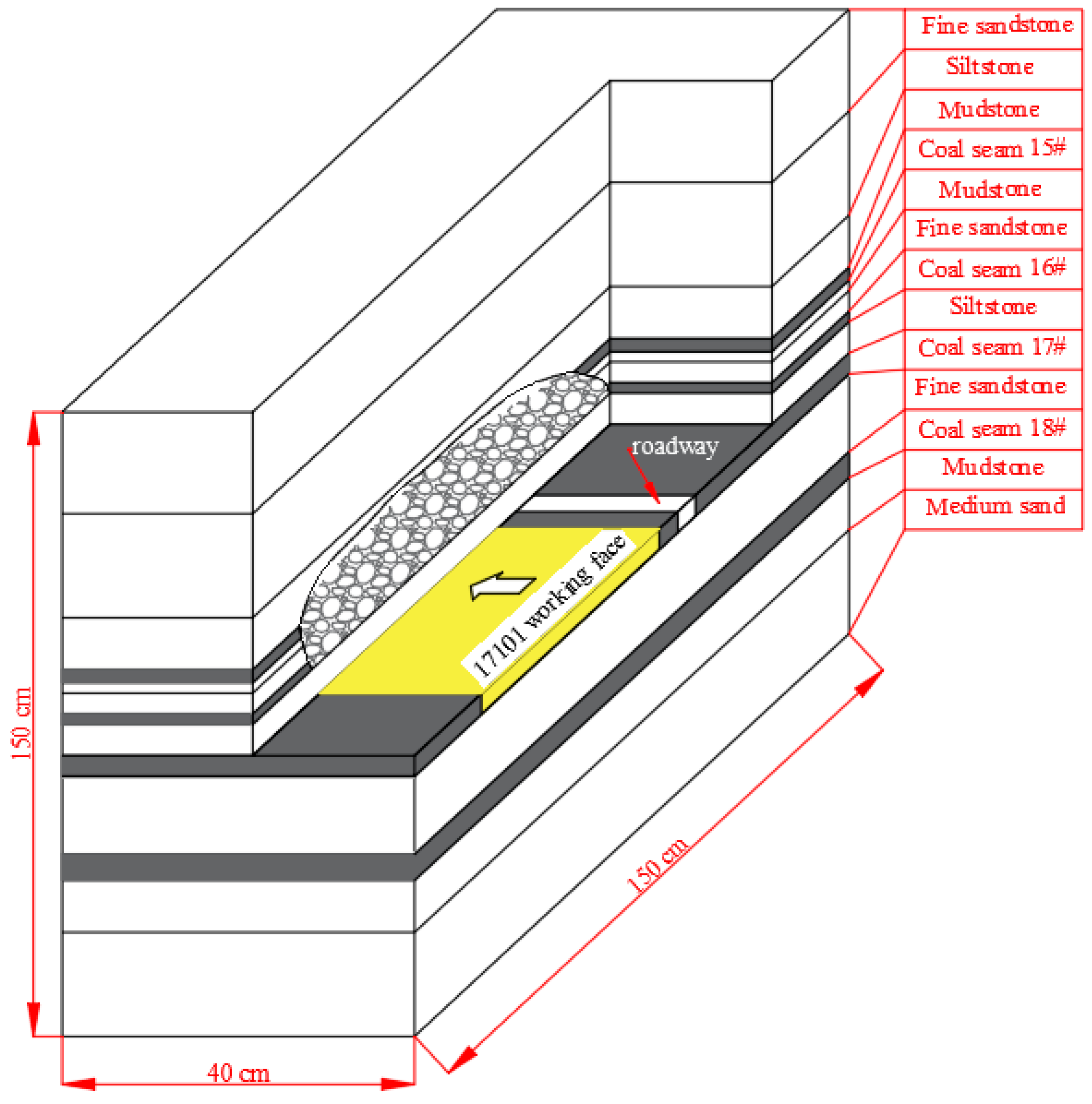
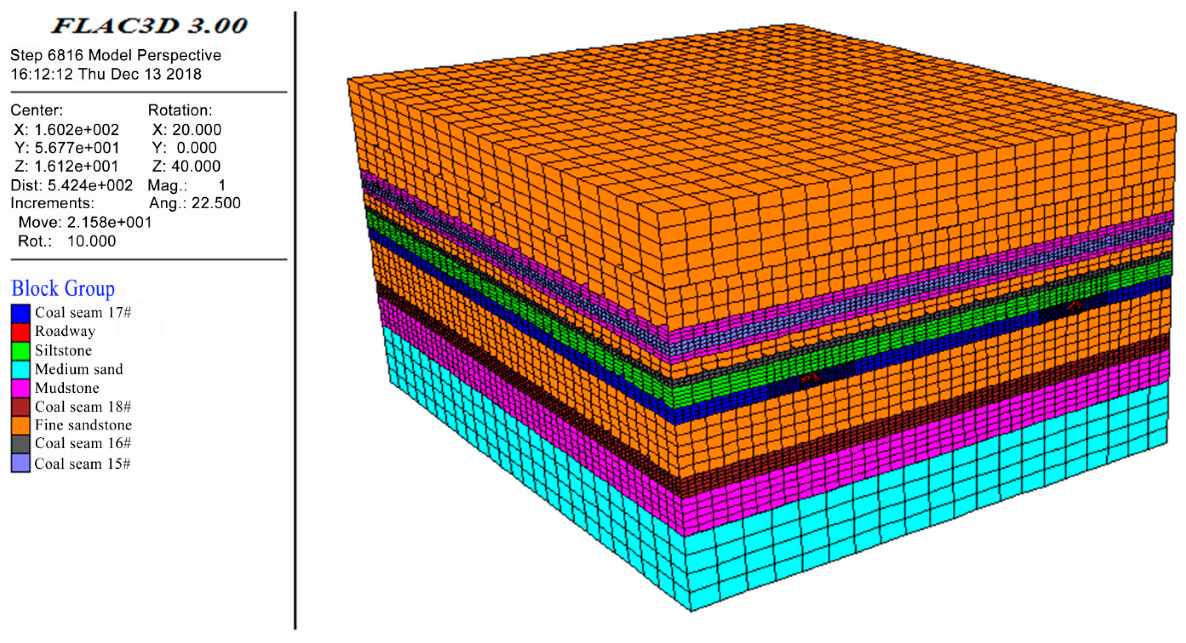
3.3.1. Establish a Physical Similarity Model

The similar simulation test frame in this experiment has a length of 1.5 m, a width of 40 cm and a height of 1.5 m. The periphery of the model and the bottom plate can be strongly restrained by the steel channel of the similar simulation test frame. The matching ratio of similar materials in each rock formation in this physical simulation experiment is the best result obtained after many experiments, as shown in Table 1. Simulate different lithology materials with different matching ratios, using gypsum and lime as cementing aterials, sand as aggregates [33,34]. The model is laid according to the geometric similarity ratio 1:100, the bulk density similarity ratio 1:1.6 and the time similarity ratio 1:10. The final laying model height is 1.2 m (see Figure 7). In this model, a total of four coal seams have been laid, among which coal seams 15#, 16#, and 17# belong to close-distance coal seams. In the actual engineering background, coal seams 15# and 16# have been mined and coal seam 17# is being mined. After the model is laid, the upper coal seams are mined in sequence to simulate the upper goaf. Then the coal seam 17# was mined to observe the fracture characteristics of the roof and the displacement of the surrounding rock of the roadway of the coal seam 17# after being affected by repeated mining. The model is a three-dimensional similar model. In the simulation process, the length and width of the model are the simulated coal seam working face layout direction and the working face forward direction respectively. That is, the simulated working face will advance 40 cm in length (actual advance 40 m) to observe the deformation and failure of the roadway.

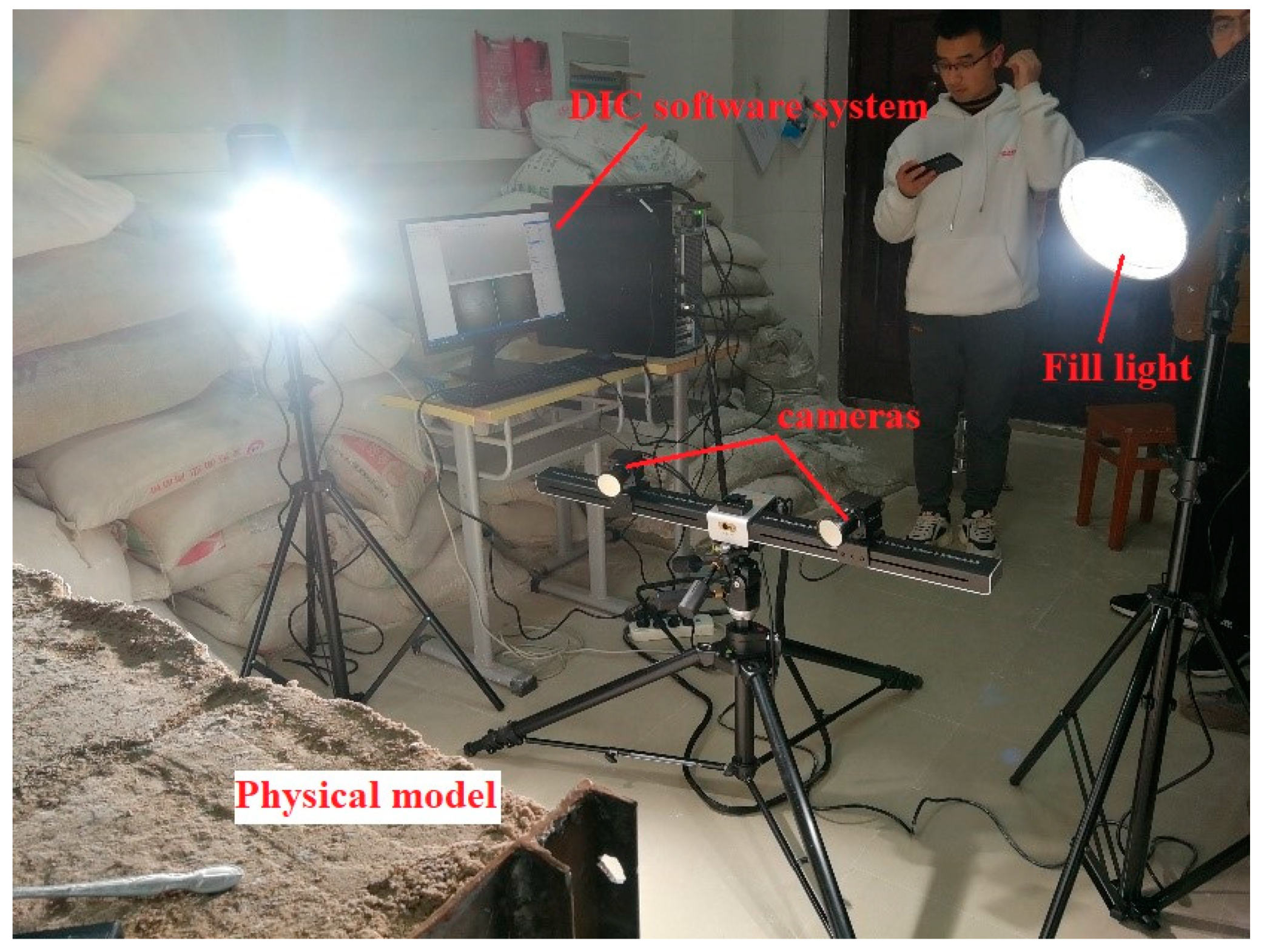
3.3.2. Monitoring Methods of Surrounding Rock Displacement of Roadway

The experiment uses a three-dimensional digital image correlation strain measurement and analysis system to calculate the strain and deformation of the whole field when the model is excavated. The three-dimensional digital image correlation strain measurement and analysis system has a flexible and easy-to-use trigger function, rich external software and hardware interfaces, and the strain measurement range can be varied from 0.01% to 1000%. It adopts the digital image correlation method and uses two high-speed cameras to collect real-time speckle images of physical objects deformed in various stages. The relevant algorithm is used to match the displacement of the object with the stereo to realize the visual analysis of the displacement field data, so as to achieve the rapid, high-precision, and real-time experimental requirements, as shown in Figure 8.

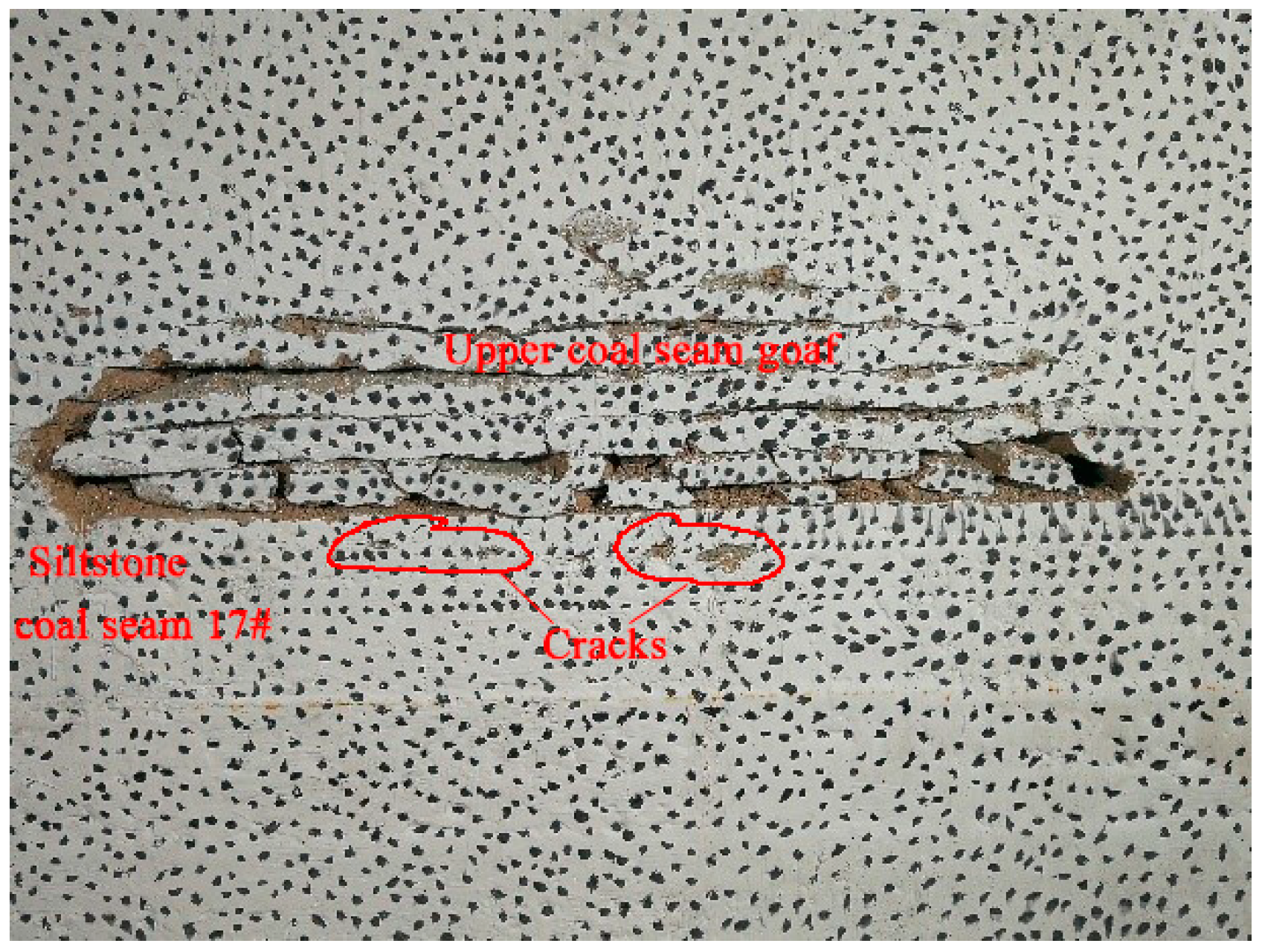
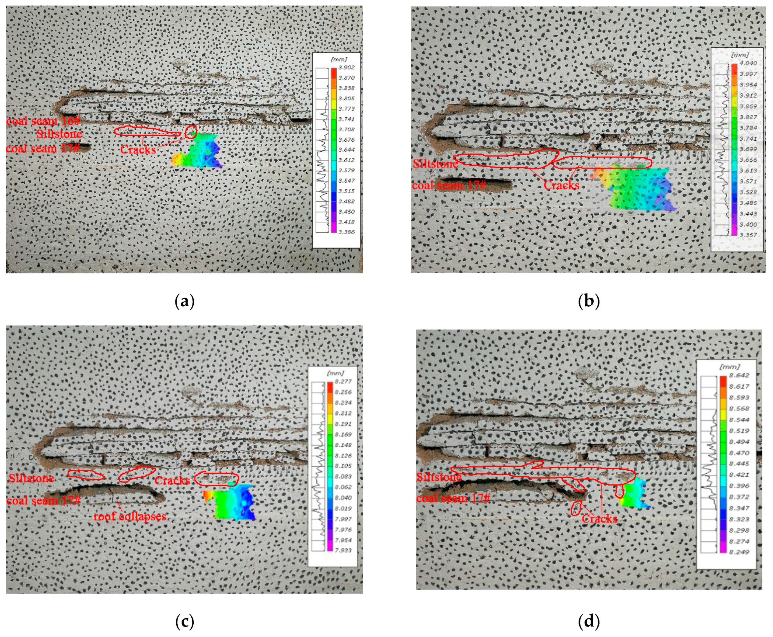
3.3.3. Analysis of Simulation Results

Mining coal seams at close distance, the upper coal seams will cause a certain degree of failure to the lower coal seam. The upper coal seams are completed as shown in Figure 9.
The development of cracks in the coal and rock mass is very complicated. When the upper coal seam is not mined, there are a large number of primary cracks in the lower coal seam and the roof. After the coal seam 17# is affected by mining, as the stress around the coal and rock mass changes, the primary cracks continue to expand into new secondary cracks in different forms. It can be clearly seen in Figure 9 that the completion of upper coal seam mining has failure the coal seam 17# and the roof to a certain degree, affecting the integrity of the coal and rock mass.
When the coal seam 17# 17,101 working face was excavated, the mining roadway had been excavated in advance. The mining plan of the simulated working face is shown in Figure 10, and the working face is advanced 40 cm (actual advance 40 m). During the mining process, Figure 11 shows the completion of coal mining in one work cycle at the working face. Here, the digital image correlation system is used to monitor the displacement of the surrounding rock of the roadway.
It can be seen from Figure 11a that the roof of the working face is basically stable, the overlying rock layer has not collapsed, and no obvious cracks appear. The DIC system monitors that the surrounding rock of the roadway begins to move, and the farther away from the working face, the smaller the displacement. Due to the change of the stress environment in front of the working face and the goaf above the coal seam 17#, which has a certain disturbing effect on the surrounding rock, the maximum displacement at this time is 3.902 mm. According to the geometric similarity ratio of 1:100, the surrounding rock of the roadway has a displacement of 39.02 cm.
It can be seen from Figure 11b that the cracks appear in the roof rock layer, and the cracks are connected with the cracks produced during the mining of the upper coal seam, and the roof of the deep roadway is slightly failure. With the excavation of the working face, the displacement of the surrounding rock of the roadway increases under the influence of mining.
It can be seen from Figure 11c that the roof collapses, forming the initial pressure. Under the disturbance of the mining of the coal seam 17#, the broken rock mass in a small area of the overlying goaf is more likely to lose stability. At this time, the disturbance of the roadway has a greater impact. The surrounding rock of the roadway has a displacement of 8.277 mm. According to the geometric similarity ratio of 1:100, that is, the roadway actually has a displacement of 82.77 cm, and the roadway is seriously failure.
It can be seen from Figure 11d that the roof will collapses with the mining because the roof above the working face is broken and cracks are developed. At this time, the roof has obvious separation cracks, but it has not broken and subsided, and the displacement of the surrounding rock of the roadway is increasing.
After the excavation of the simulated 17,101 working face is completed, as shown in Figure 12, the roadway failure in front and behind the model excavation is shown.
Figure 12a shows the failure of the surrounding rock of the roadway under the influence of mining in front of the model. With the passage of time, the roof of the coal seam 17# is broken and its strength is reduced due to the mining of the upper coal seam, so that the roof is more likely to lose stability during the mining of the coal seam 17#. It has all collapsed and re-compacted to form a new ‘masonry beam’ structure. At this time, the calibration point of the digital image correlation has been destroyed, so the relevant displacement cloud image has not been recorded. The failure of the surrounding rock of the roadway intensified under repeated disturbances.
Figure 12b shows the deformation and failure of the surrounding rock of the roadway under the influence of mining behind the model. At this time, there have been obvious cracks in the roof above the roadway. In addition, there are obvious cracks in the coal pillar of the roadway protection, and there are also obvious cracks in the solid coal body, and the stability of the surrounding rock of the roadway is poor.

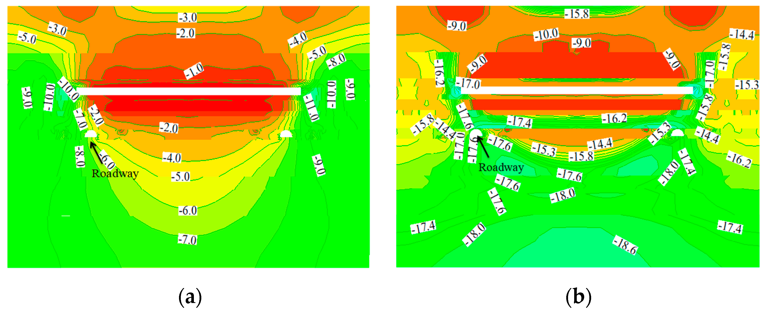
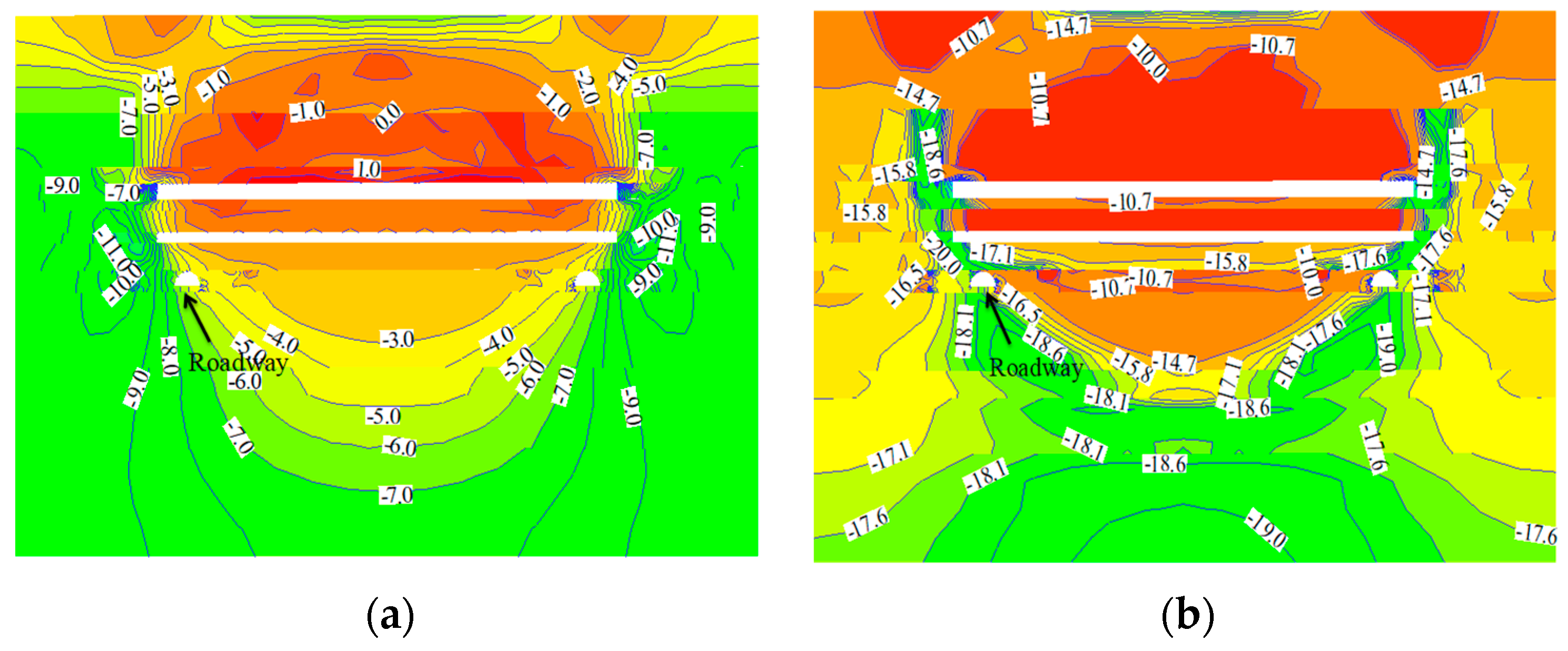
3.4. Stress Distribution Characteristics of Roadway Surrounding Rock Based on Numerical Simulation

The stress of the surrounding rock is the external factor that affects roadway stability, and it is the main factor determining roadway failure. To obtain the stress distribution characteristics around the roadway under repeated mining, the maximum and minimum principal stresses around the roadway after mining coal seams #15 and #16 are simulated using FLAC3D. The mechanical parameters of the coal and rock mass are shown in Table 2. The numerical model is shown in Figure 13. The left and right boundaries, front and back boundaries, and lower boundaries of the numerical model adopt rolling boundary conditions. The length, width, and height of the established model are respectively 200 × 200 × 120, representing an actual length of 200 m; a width of 200 m; and a height of 120 m. The working face length is 120 m, and in order to eliminate the boundary effect, a width of 35 m is left at each end of the model. In addition, between the roadway and the working face, there is a 10 m-length coal pillar for roadway protection. Using the Mohr Coulomb constitutive model, horizontal constraints are added to both the front, back, left, and right boundaries of the model, so that the horizontal displacement of the front, back, left, and right boundaries is 0. The bottom boundary of the model also writes the corresponding command to make it immobile, so that the horizontal displacement and vertical displacement of the bottom boundary are both 0. The vertical stress on the upper boundary is calculated according to the gravity of the overlying rock. Since the distance from the upper boundary to the ground surface in the actual engineering background is 494.5 m, the calculated vertical stress should be 12.36 MPa. The horizontal stress of the front, back, left, and right is considered according to the hydrostatic pressure.
The simulation of coal seams 15# and 16# is completed, and the model is sliced along a plane vertical to the axial direction of the roadway to obtain the stress distribution of the surrounding rock of the roadway under the influence of primary and secondary mining, as shown in Figure 14 and Figure 15.
The following can be seen:
(1) The stress concentration occurs under the coal pillar, and an area with a certain range of stress reduction appears under the goaf after mining coal seam 15#. At this time, the minimum principal stress is −6.0 MPa, and the maximum principal stress is −17.6 MPa. The maximum principal stress is approximately 2.93 times the minimum principal stress.
(2) After coal seams 15# and 16# are mined, the pressure of coal seam 17# is further decompressed, and the stress concentration degree is reduced accordingly. However, the horizontal distance between the roadway and the edge of the coal pillar is 10 m, which is close to the coal pillar. Affected by the stress concentration degree of the coal pillar, the minimum principal stress at the mining roadway axis is −6.0 MPa, the maximum principal stress is −18.6 MPa, and the maximum principal stress is approximately 3.1 times the minimum principal stress.
From the surrounding rock stress distribution, it can be known that the maximum principal stress in the direction of the roadway axis of coal seam 17# is approximately three times that of the minimum principal stress, although it belongs to the stress reduction when the roadway is located at a horizontal distance of 10 m from the edge of the pillar. According to the Moore–Coulomb strength criterion, the greater the difference between the maximum principal stress and the minimum principal stress, the more easily roadway failure occurs. As the maximum principal stress is a horizontal stress and the minimum principal stress is a vertical stress, the failure degree of the two sides of the roadway rib is more serious than that of the roof and floor under high horizontal stress. Therefore, the location of the roadway is unreasonable, as a reasonable location is a horizontal distance of at least 15–20 m from the edge of the coal pillar.
According to the numerical simulation results, under the influence of repeated mining, the maximum principal stress of the surrounding rock of the roadway is 3.1 times of the minimum principal stress. At this time, the surrounding rock of the roadway is easily failure. It also shows that, under high horizontal stress, two sides of the roadway will suffer more failure than the roof and floor. Combined with the simulation results of physical similarity, it can be clearly observed that the cracks in the surrounding rock of the roadway under the influence of repeated mining are more developed, and the failure of the surrounding rock is intensified. In addition, the surrounding rock failure on two sides of the roadway rib is the most serious, and the results and the numerical simulation results complement and verify each other. Finally, through the above analysis results of the numerical simulation, physical similarity simulation and field investigation, it is concluded that the instability mechanism of the surrounding rock under the repeated mining of close-distance coal seam groups is as follows: the surrounding rock of the roadway has low strength, low bearing capacity, and poor self-stabilization ability, and it is vulnerable to engineering disturbance and fragmentation. Due to repeated mining, the surrounding rock cracks have strong sensitivity, and long-range loosening and breaking easily occur due to strong disturbances from the adjacent roadway and working face mining over a long period of time. The layout location of the roadway is unreasonable, and the difference between the maximum principal stress and the minimum principal stress of the roadway is large. Surrounding rock expansion deformation in a large range occurs under high horizontal stress, and the deformation and destruction of the two sides of the roadway rib are more serious than those of the roof and floor. When the support strength is insufficient, large-scale roof caving, coal-rib collapse, and strong floor heave of the roadway occur. At the same time, ordinary anchor cables cannot resist the high horizontal stress due to insufficient shear resistance, which results in contortion bending and shear failure.

4. Stability Control of Roadway Surrounding Rock

4.1. Control Principle

According to the above analysis, three factors affecting the stability of the close-distance coal seam roadway, adopting reasonable support measures, and improving the strength and the stress state of the surrounding rock are key to realizing the stability control of the surrounding rock of such roadways.
Therefore, the roadway surrounding rock under repeated mining in the close-distance coal seam groups should be controlled as follows: the roadway should be located where the principal stress difference is small; areas of stress concentration should be avoided; the extension of the support body should be increased so that it can adapt to the large deformation of the surrounding rock; the support should not be invalid; and the integrity and strength of the destroyed surrounding rock should be improved to improve the self-supporting ability and the ability to transmit horizontal stress evenly from the surrounding rock while fully utilizing the anchorage effect of the bolts and cables to form a structure that can bear high stress.
Combined with the maintenance characteristics of the roadway surrounding rock under repeated mining in this mine, a repair scheme—i.e., long bolts + high-strength cables + U-shaped steel shed + grouting—is proposed.

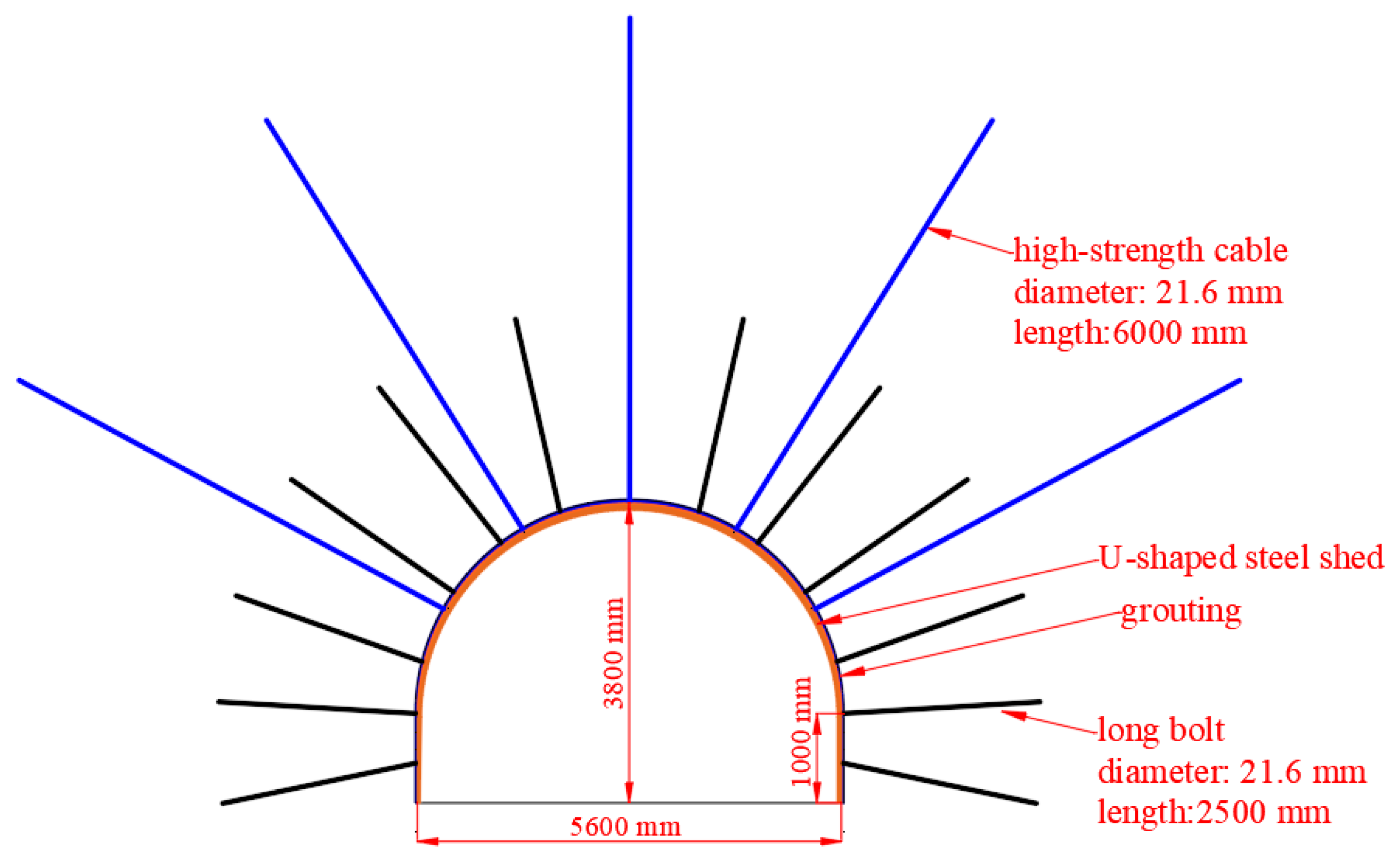
4.2. Control Technology

To address the instability characteristics of the roadway surrounding rock, a U-shaped steel shed and grouting support are added on the basis of the original bolt-cable support, as shown in Figure 16. The shallow surrounding rock of the roadway under the repeated mining of close-distance coal seam groups is relatively fragmented, resulting in a significant reduction in its ability to transmit horizontal stress and causing failure to the deep surrounding rock. The use of high prestressing long bolts to support the roadway can form a prestressing bearing structure with a certain thickness and limit the formation of new failure to the surrounding rock outside the anchorage area. Using a high-elongation anchor cable to reinforce the surrounding rock can provide a high-pressure stress to the roadway surrounding rock and form a skeleton network structure with a compressive stress zone of shallow anchor, which makes the prestressed bearing structure have a greater stiffness and greatly improves the ability to resist a high horizontal stress. The U-shaped steel shed can provide enough support resistance to the surrounding rock during the deformation process and closely contact the whole section of the surrounding rock, it can evenly transfer a high horizontal stress to the support to avoid serious failure of the surrounding rock due to stress concentration. The grouting reinforcement of the surrounding rock and the grouting fluid used to improve the stress state of the surrounding rock increase the anchor ability, integrity, and strength of the surrounding rock while uniformly distributing the surrounding rock stress.

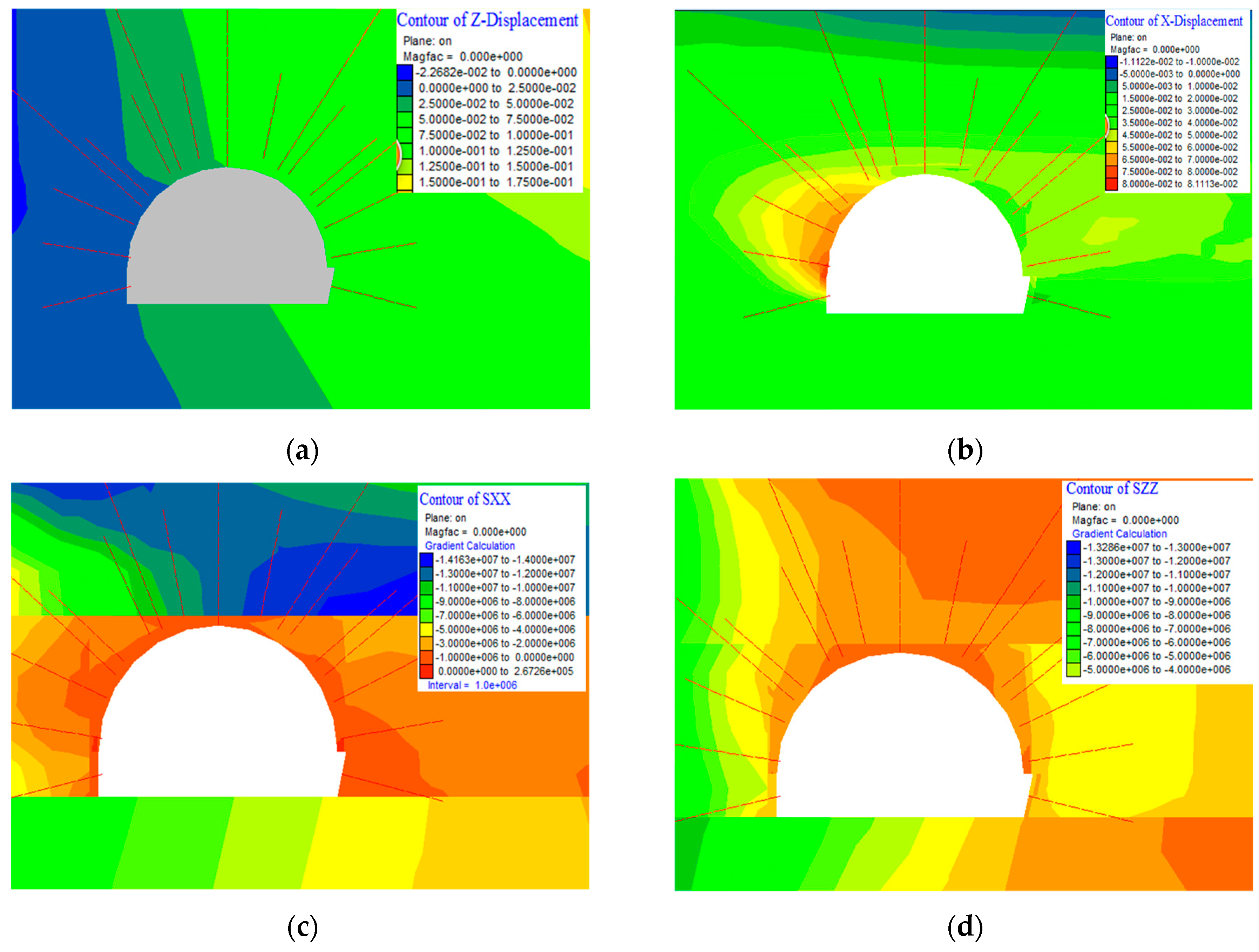
4.3. Numerical Analysis of the Control Mechanism

To obtain the control mechanism of the roadway surrounding rock of the repair scheme and the actual effect of this control technology (i.e., long bolt + high-strength anchor cable + U-shaped steel shed + grouting) under repeated mining, considering the geology and mining conditions of the mine’s close-distance coal seam groups, the distribution characteristics of the stress and displacement of the roadway surrounding rock are simulated using FLAC3D. The simulation process is consistent with the previous Section 3.4, but the parameter assignment of the different support scheme to be proposed is fully considered in the modeling process. The control effect diagram of the roadway surrounding rock is shown in Figure 17.
The figures and table show the following:
(1) The distribution pattern of the principal stress of roadway surrounding rock changed significantly: the maximum principal stress peak value location changed from 2.0 m in the left side rib, roof and floor of the roadway to 2.0 m in the roof of the roadway, and the peak value of the stress decreased from 20.1 MPa to 14.1 MPa. The minimum principal stress peak value location changed from 2.0 m in the left side rib, roof, and floor of the roadway to the left side rib of the roadway, and the peak value of the stress decreased from 8 MPa to 6 MPa.
(2) After using combined support technology, the deformation of the roadway surrounding rock in each part is obviously reduced. The maximum vertical displacements of the roof, floor and side rib of the roadway are 75, 50, and 50 mm, respectively. The maximum horizontal displacements of the roof, floor and side rib of the roadway are 35, 40, and 80 mm, respectively.
According to this numerical analysis, after using combined support technology, increases the lateral compressive stress of the surrounding rock and increases the residual strength of the shallow surrounding rock, enhancing the ability to withstand horizontal stress and restraining the deep transfer of the high horizontal stress. The deformation of the surrounding rock in each part of the roadway is significantly reduced, and the large deformation is suppressed. The deformation of the roadway surrounding rock is within a safe and controllable range. The ‘long anchor + high strength’ under repeated mining of close-range coal seams was successfully verified. Effectiveness of surrounding rock control technology of roadway with long bolts + high-strength cables + U-shaped steel shed + grouting.

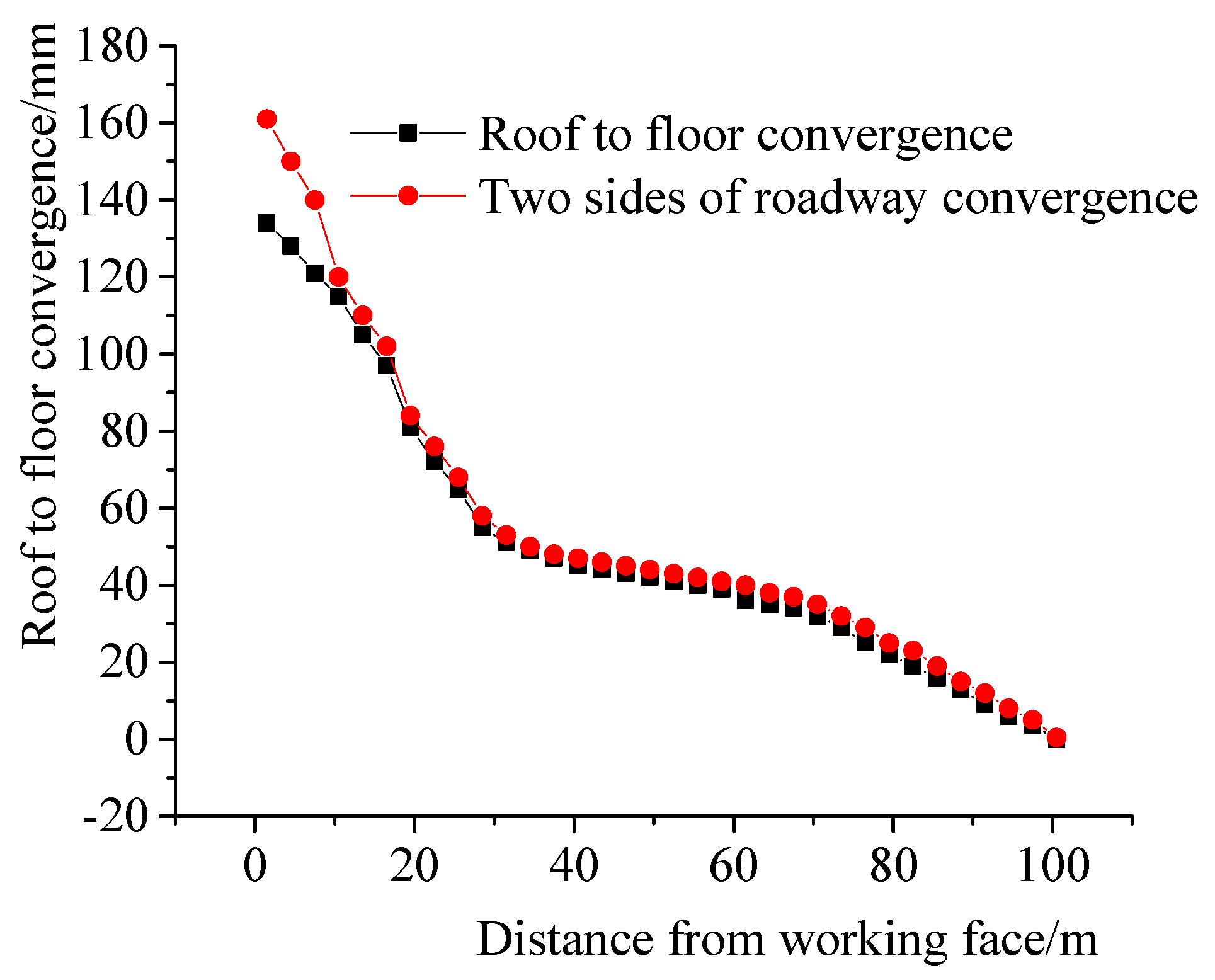
4.4. Observation of the Surrounding Rock Deformation and Rock Pressure of the Roadway

To further evaluate the effect of the roadway surrounding rock restoration, the deformation characteristics of the roof, floor and two sides of the roadway are observed. Measuring points are set up 60 m from the working face for the roof, floor and two sides of the roadway. The deformation characteristics of the roadway are observed while the working face advances. The observation results are shown in Figure 18.
It can be seen that, when the distance of the measuring points from the coal face is 100 m, the convergence of the roof to the floor and the two side ribs of the roadway is very small. As the excavation of the coal seam, due to repeated mining, the displacement of the roof to the floor and the two side ribs of the roadway gradually increases. The maximum convergence of the roof to the floor is 134 mm, the maximum convergence of the two sides of the roadway rib is 161 mm, and the deformation amount of the roadway surrounding rock is within the safe and controllable range.
The observation results show that the repair scheme (i.e., long bolt + high-strength anchor cable + U-shaped steel shed + grouting) applied to the roadway surrounding rock improves the stress state of the surrounding rock, effectively reducing the deformation of the roadway surrounding rock. The technology greatly improves the supporting effect and achieves the effective control of the surrounding rock deformation under repeated mining in close-distance coal seam groups.

5. Discussion

In order to study the stability and control of roadway surrounding rock under repeated mining, this article adopts a variety of research methods including indoor rock mechanics experiments, physical similar simulation test, numerical simulations, and field measurements. The results of multiple methods are mutually verified and complementary to each other to better explore the problem together. Each method in this article has its own advantages, and the research focus on the same problem mentioned above is also different. For example, indoor rock mechanics experiments are mainly for exploring the strength of surrounding rock, which is an internal factor that affects the stability of the roadway. On-site drilling and exploration of the roadway is mainly to clarify the development of the cracks in the roadway surrounding rock that is affected by repeated mining, because the development and distribution characteristics of the cracks are also important factors that affect the stability of the surrounding rock. The physical similarity simulation is mainly to restore the site environment to the greatest extent according to a specific similarity ratio, and explore the deformation, displacement, and failure of the roadway surrounding rock under the influence of repeated mining. The simulation results are intuitive and vivid, but the experimental process is complicated and time-consuming. Numerical simulation is mainly to study the stress distribution and displacement of the roadway surrounding rock affected by repeated mining, and to simulate the stability of the roadway surrounding rock after the new support scheme, which also restores the site environment to the greatest extent. The use of on-site roadway deformation monitoring is mainly to explore the results of the actual roadway surrounding rock repair after the adoption of the new support technology.
Here, based on the comparative analysis of the results of physical similarity simulation, numerical simulation, and the field measurement results of the roadway surrounding rock, it can be clarified that the above two methods have strong practicability and feasibility in studying the stability and control of the roadway surrounding rock under repeated mining. However, the numerical simulation results are more accurate and more convenient in comparison. Therefore, numerical simulation method can be combined with field measurements and widely used in scientific research and practice under such conditions. However, if necessary, the auxiliary verification of physical similarity simulation experiment is required. As a result, the reliability is better in field practice.
In addition, in the similar simulation experiment in this article, a newer monitoring method (digital image correlation technology) is introduced, which is used to monitor the deformation and failure of the roadway surrounding rock in the process of simulating coal seam excavation in real time. This method is relatively novel. The monitoring object in this article is only the roadway surrounding rock. However, it can be extended to the monitoring of working face and roof displacement and strain in similar simulation experiments in the future, which has a great application prospect.

6. Conclusions

(1) The reasons for the failure of the roadway surrounding rock under repeated mining in the close-distance coal seam groups mainly involve the following 4 aspects: (a) The uniaxial compression experiment shows that the average strength of mudstone and siltstone are 9 MPa and 29 MPa respectively, and the surrounding rock of the roadway belongs to soft rock. The rock strength of roadway surrounding rock is low, and the bearing capacity is low; (b) Borehole observations through the loose circle of surrounding rock of the roadway show that the cracks development degree of roadway surrounding rock is large and the sensitivity is strong; Physical similarity simulation experiments combined with DIC surrounding rock displacement monitoring show that the surrounding rock of the roadway is seriously failure under repeated mining, and the cracks are relatively developed; (c) Numerical simulation shows that the maximum principal stress and minimum principal stress of the roadway are −18.6 MPa and −6.0 MPa respectively. The location of the roadway is unreasonable, and the difference between maximum principal stress and minimum principal stress is large; (d) The horizontal stress of the roadway is large, approximately three times that of the vertical stress.
(2) The stability control of roadway surrounding rock under repeated mining of close-distance coal seam groups should consider the following: (a) The roadway should be located at the place where the principal stress difference is small to avoid areas of stress concentration; (b) Support should be extended to adapt to the deformation of the roadaway surrounding rock, and the support should not be invalid; (c) The integrity and strength of destroyed surrounding rock should be improved to improve self-supporting ability, and the ability to transmit horizontal stress evenly of surrounding rock while fully considering the anchorage effect of bolts and cables to form a structure that can bear high stress.
(3) The comprehensive repair scheme of roadway surrounding rock deformation (i.e., long bolt + high-strength anchor cable + U-shaped steel shed + grouting) improves the stress state of surrounding rock and effectively reduces the deformation of roadway surrounding rock. The peak value of the maximum principal stress decreased from 20.1 MPa to 14.1 MPa; the maximum displacement from roof to floor of the roadway is 134 mm, and the maximum sides rib displacement of the roadway is 161 mm. The deformation of the roadway surrounding rock is within a safe and controllable range. The technology greatly improves the support and effectively controls surrounding rock deformation under repeated mining of close-distancing coal seam groups.

Author Contributions

Y.X.: Methodology, Software, Formal analysis, Investigation, Data curation, Writing—original draft preparation. D.K.: Conceptualization, Data curation, Writing—review and editing, Visualization, Project administration, Funding acquisition. Z.C.: Methodology, Software, Validation, Writing—review and editing. Z.W.: Conceptualization, Validation, Data curation, Writing—review and editing, Visualization. Z.M.: Formal analysis, Investigation, Writing—review and editing. G.W.: Validation, Resources, Project administration, Funding acquisition. Y.L.: Conceptualization, Resources, Supervision. All authors have read and agreed to the published version of the manuscript.

Funding

This research was funded by National Natural Science Foundation of China Youth Fund (No. 51904082), the National Natural Science Foundation of China Regional Fund (No. 52064005, 52164005, 52164002), the funding from Guizhou Science and Technology Plan Project (Qianke Science Foundation (2020) 1Y214), the funding from Guizhou Science and Technology Plan Project (Qianke Science Support (2021) General 399), The Opening Project Fund of Key Laboratory of Mining Disaster Prevention and Control (MDPC202019) and the Scientific and Technological Innovation Talents Team in Guizhou Province (Project No. [2019]5619).

Institutional Review Board Statement

Not applicable.

Informed Consent Statement

Not applicable.

Data Availability Statement

All data and models or used during the study appear in the submitted article.

Acknowledgments

The authors would like to thank the Mining Engineering Laboratory of the School of Mining and Mining College of Guizhou University for its rock mechanics experimental support and the support of the field test in the Panjiang mining area in Guizhou Province.

Conflicts of Interest

The authors declare no conflict of interest.

References

  1. Ning, J.; Wang, J.; Tan, Y.; Xu, Q. Mechanical mechanism of overlying strata breaking and development of fractured zone during close-distance coal seam group mining. Int. J. Min. Sci. Technol. 2020, 30, 207–215. [Google Scholar] [CrossRef]
  2. Kong, D.; Cheng, Z.; Zheng, S. Study on the failure mechanism and stability control measures in a large-cutting-height coal mining face with a deep-buried seam. Bull. Eng. Geol. Environ. 2019, 78, 6143–6157. [Google Scholar] [CrossRef]
  3. Kong, D.; Xiong, Y.; Cheng, Z.; Wang, N.; Wu, G.; Liu, Y. Stability analysis of coal face based on coal face-support-roof system in steeply inclined coal seam. Geomech. Eng. 2021, 25, 233–243. [Google Scholar] [CrossRef]
  4. Xie, S.; Xu, X.; Chen, D.; Sun, Y.; Wang, E.; Wu, X.; Duan, X.; Jiang, Z.; Qi, P.; Shi, S. Failure Mechanism and Control Technology of Thick and Soft Coal Fully Mechanized Caving Roadway under Double Gobs in Close Coal Seams. Shock Vib. 2020, 2020, 8846014. [Google Scholar] [CrossRef]
  5. Suchowerska, A.M.; Merifield, R.S.; Carter, J.P. Vertical stress changes in multi-seam mining under supercritical longwall panels. Int. J. Rock Mech. Min. 2013, 61, 306–320. [Google Scholar] [CrossRef]
  6. Pan, R.; Ma, Z.; Yu, M.; Wu, S.; Palmeri, A. Research on the Deformation Characteristics and Support Technology of a Bottom Gas Extraction Roadway under Repeated Interference. Adv. Civ. Eng. 2019, 2019, 1413568. [Google Scholar] [CrossRef]
  7. Ghosh, N.; Agrawal, H.; Singh, S.K.; Banerjee, G. Optimum Chain Pillar Design at the Deepest Multi-Seam Longwall Workings in India. Min. Metall. Explor. 2020, 37, 651–664. [Google Scholar] [CrossRef]
  8. Prusek, S.; Masny, W. State of the art of the gateroads in Polish coal mining. Min. Rep. 2013, 149, 28–33. [Google Scholar] [CrossRef]
  9. Wang, K.; Wang, L.; Ren, B. Failure Mechanism Analysis and Support Technology for Roadway Tunnel in Fault Fracture Zone: A Case Study. Energies 2021, 14, 3767. [Google Scholar] [CrossRef]
  10. Cui, F.; Dong, S.; Lai, X.; Chen, J.; Jia, C.; Zhang, T. Study on the Fracture Law of Inclined Hard Roof and Surrounding Rock Control of Mining Roadway in Longwall Mining Face. Energies 2020, 13, 5344. [Google Scholar] [CrossRef]
  11. Yu, J.; Liu, G.; Cai, Y.; Zhou, J.; Liu, S.; Tu, B. Time-Dependent Deformation Mechanism for Swelling Soft-Rock Tunnels in Coal Mines and Its Mathematical Deduction. Int. J. Geomech. 2020, 20, 04019186. [Google Scholar] [CrossRef]
  12. Huang, Q.; Wang, X.; Chen, X.; Qin, D.; Chang, Z. Evolution of Interior and Exterior Bearing Structures of the Deep-Soft-Rock Roadway: From Theory to Field Test in the Pingdingshan Mining Area. Energies 2020, 13, 4357. [Google Scholar] [CrossRef]
  13. Ding, K.; Gu, S.; Guo, J.; Gu, D.; Liu, Z.; Wei, B. Numerical Investigation on Factors Affecting Stability of Roadway Surrounding Rock with Fractured Roof. Geotech. Geol. Eng. 2019, 37, 2373–2385. [Google Scholar] [CrossRef]
  14. Xie, J.; Xu, J.; Wang, F.; Guo, J.; Liu, D. Deformation effect of lateral roof roadway in close coal seams after repeated mining. Int. J. Min. Sci. Technol. 2014, 24, 597–601. [Google Scholar] [CrossRef]
  15. Tulu, I.B.; Esterhuizen, G.S.; Klemetti, T.; Murphy, M.M.; Sumner, J.; Sloan, M. A case study of multi-seam coal mine entry stability analysis with strength reduction method. Int. J. Min. Sci. Technol. 2016, 26, 193–198. [Google Scholar] [CrossRef] [Green Version]
  16. Lin, N.; Sasaoka, T.; Shimada, H.; Hamanaka, A.; Matsuia, K. Numerical Analysis of Interaction Effects in Double Extra-thick Coal Seams Mining. Procedia Earth Planet. Sci. 2013, 6, 343–349. [Google Scholar] [CrossRef] [Green Version]
  17. Li, X.; Liu, C.; Yu, C. Influence on roadways caused by the longwall mining in the adjacent upper seam. Electron. J. Geotech. Eng. 2015, 20, 5913–5926. [Google Scholar]
  18. Lian, Z.; Wang, J.; Hao, C. Numerical simulation and experimental research of surrounding rock deformation of floor roadway under short-distance coal seam group combined mining. J. Coal Sci. Eng. 2010, 16, 230–234. [Google Scholar] [CrossRef]
  19. Wang, J.; Ning, J.; Tan, Y.; Hu, S.; Guo, W. Deformation and failure laws of roadway surrounding rock and support optimization during shallow-buried multi-seam mining. Geomat. Nat. Hazards Risk 2020, 11, 191–211. [Google Scholar] [CrossRef]
  20. Waclawik, P.; Kukutsch, R.; Konicek, P.; Ptacek, J.; Kajzar, V.; Nemcik, J.; Stas, L.; Soucek, K.; Vavro, M. Stress State Monitoring in the Surroundings of the Roadway Ahead of Longwall Mining. Procedia Eng. 2017, 191, 560–567. [Google Scholar] [CrossRef]
  21. Fang, X.; Guo, M.; Lv, Z. Instability mechanism and prevention of roadway under close-distance seam group mining. Chin. J. Rock Mech. Eng. 2009, 28, 2060–2066. [Google Scholar]
  22. Chen, J.; Liu, P.; Zhao, H.; Zhang, C.; Zhang, J. Analytical studying the axial performance of fully encapsulated rock bolts. Eng. Fail. Anal. 2021, 128, 105580. [Google Scholar] [CrossRef]
  23. Wang, L.; Chang, C.; Yang, Z. Combined support technology of roadway under mined gob of ultra-distance seams in deep mine. J. Min. Saf. Eng. 2018, 35, 689–692. [Google Scholar] [CrossRef]
  24. Wang, H.; Jiang, Y.; Zhao, Y.; Wang, T.; Yang, T.; Ning, T. Determination of reasonable roadway position during extraction of closed coal seam based on energy theory. Chin. J. Rock Mech. Eng. 2015, 34, 4024–4029. [Google Scholar] [CrossRef]
  25. Sun, X.; Liu, Y.; Wang, J.; Li, J.; Cui, X. Study on Three-Dimensional Stress Field of Gob-Side Entry Retaining by Roof Cutting without Pillar under Near-Group Coal Seam Mining. Processes 2019, 7, 552. [Google Scholar] [CrossRef] [Green Version]
  26. Gao, R.; Yu, B.; Meng, X. Stress distribution and surrounding rock control of mining near to the overlying coal pillar in the working face. Int. J. Min. Sci. Technol. 2019, 29, 881–887. [Google Scholar] [CrossRef]
  27. Kang, Q.; Tang, J.; Hu, H.; Zhang, W. Stress distribution rule of roadway affected by overhead mining in gently inclined coal seams group. Trans. Nonferr. Met. Soc. China 2011, 21, 529–535. [Google Scholar] [CrossRef]
  28. Kong, D.; Pu, S.; Cheng, Z.; Wu, G.; Liu, Y. Coordinated Deformation Mechanism of the Top Coal and Filling Body of Gob-Side Entry Retaining in a Fully Mechanized Caving Face. Int. J. Geomech. 2021, 21. [Google Scholar] [CrossRef]
  29. Liu, Z.; Qin, T. Cutting Roof Roadway Regional Stress Characteristics Numerical Analysis of Thin Coal Seam Group. Appl. Mech. Mater. 2014, 3013, 1382–1385. [Google Scholar] [CrossRef]
  30. Li, B.; Wang, X.; Liu, Z.; Li, T. Study on multi-field catastrophe evolution laws of water inrush from concealed karst cave in roadway excavation: A case of Jiyuan coal mine. Geomat. Nat. Hazards Risk 2021, 12, 222–243. [Google Scholar] [CrossRef]
  31. Zheng, S.; Lou, Y.; Kong, D.; Wu, G.; Liu, Y. The Roof Breaking Characteristics and Overlying Strata Migration Law in Close Seams Group Under Repeated Mining. Geotech. Geol. Eng. 2019, 37, 3891–3902. [Google Scholar] [CrossRef]
  32. Cheng, Z.; Li, L.; Zhang, Y. Laboratory investigation of the mechanical properties of coal-rock combined body. Bull. Eng. Geol. Environ. 2020, 79, 1947–1958. [Google Scholar] [CrossRef]
  33. Xiong, Y.; Kong, D.; Wu, G.; Li, Q. Study on the Support Capacity Determination and Movement Law of Overlying Strata in a Thin-Bedrock Large-Cutting-Height Longwall Panel. Geotech. Geol. Eng. 2021, 39, 2347–2358. [Google Scholar] [CrossRef]
  34. Lou, J.; Gao, F.; Yang, J.; Ren, Y.; Li, J.; Wang, X.; Yang, L. Characteristics of evolution of mining-induced stress field in the longwall panel: Insights from physical modeling. Int. J. Coal Sci. Technol. 2021. [Google Scholar] [CrossRef]
Figure 1. Vertical section of coal seams.
Energies 14 05193 g001
Figure 2. Layout drawing of working face and roadway.
Energies 14 05193 g002
Figure 3. Deformation and failure characteristics of the roadway.
Energies 14 05193 g003
Figure 4. Stress–strain curve of mudstone under uniaxial compression.
Energies 14 05193 g004
Figure 5. Stress–strain curves of sandstone specimens under uniaxial compression.
Energies 14 05193 g005
Figure 6. Crack distribution of the roof at a horizontal distance of 45.6 m from the working face: (a) Away from roadway roof: 0.6 m; (b) Away from roadway roof: 1.8 m; (c) Away from roadway roof: 2.8 m; (d) Away from roadway roof: 5 m.
Energies 14 05193 g006aEnergies 14 05193 g006b
Figure 7. Similar simulation model.
Energies 14 05193 g007
Figure 8. Digital image correlation system.
Energies 14 05193 g008
Figure 9. State of completion of upper coal seams mining.
Energies 14 05193 g009
Figure 10. Excavation simulation plan diagram of coal seam 17#.
Energies 14 05193 g010
Figure 11. Displacement of roadway surrounding rock during one coal mining cycle at 17,101 working face: (a) The roof is basically stable; (b) Cracks appear in the roof rock layer; (c) Roof collapses; (d) Cracks development.
Energies 14 05193 g011
Figure 12. Failure of surrounding rock of roadway under repeated mining: (a) Surrounding rock conditions of the roadway in front of the model; (b) Surrounding rock conditions of the roadway behind the model.
Energies 14 05193 g012
Figure 13. Numerical simulation model.
Energies 14 05193 g013
Figure 14. Stress distribution characteristics of floor stress after coal seam 15# mining: (a) Minimum principal stress (MPa); (b) Maximum principal stress (MPa).
Energies 14 05193 g014
Figure 15. Stress distribution characteristics of the floor after coal seam 16# mining: (a) Minimum principal stress (MPa); (b) Minimum principal stress (MPa).
Energies 14 05193 g015
Figure 16. Schematic presentation of proposed solutions.
Energies 14 05193 g016
Figure 17. Stress distribution characteristics of floor after coal mining: (a) Vertical displacement; (b) Horizontal displacement; (c) Minimum principal stress; (d) Maximum principal stress.
Energies 14 05193 g017
Figure 18. Displacement change curves of the roadway.
Energies 14 05193 g018
Table 1. Material ratio of similar simulation experiment.
LithologyThickness/cmMatching NumberSand/kgLime/kgGypsum/kgTotal Weight/kg
Fine sandstone20.00224133133266531
Siltstone20.0022155212
Mudstone10.00733612626113
Coal seam 15#2.507321285536219
Mudstone2.00224551121
Fine sandstone4.0053423141855
Coal seam 16#2.0072247141474
Siltstone6.00744158831
Coal seam 17#4.0022155314
Fine sandstone15.0064428191965
Coal seam 18#5.00733783333145
Mudstone10.002211010526
Medium sand20.00733642828119
Table 2. Mechanical parameters of coal and rock mass.
LithologyDensity/kg/m3Cohesion/MPaFriction/°Bulk/GPaShear/GPaTension/MPa
Coarse sand23685.844310.129.655.08
Medium sand25005.9427.386.964.56
Siltstone sand25405.2406.855.473.86
Fine sandstone26004.38395.274.693.35
Mudstone25501.24374.162.833.02
Coal seam13500.5303.952.21.04
Publisher’s Note: MDPI stays neutral with regard to jurisdictional claims in published maps and institutional affiliations.

