Abstract
This article discusses the problems of exhaust gas emissions in the context of the possibility of their reduction through the use of fuels with hydrogen as an additive or hydrotreatment. These fuels, thanks to their properties, may be a suitable response to more and more demanding restrictions on exhaust emissions. The use of such fuels in reactivity controlled dual fuel engines (RCCI) is currently the most effective way of using them in internal combustion (IC) engines. Low-temperature combustion in this type of engine allows the use of all modern fuels intended for combustion engines with high thermal efficiency. Thermal efficiency higher than in classic engines allows for additional reduction of CO2 emissions. In this work, the research on this subject was compiled, and conclusions were drawn as to further possibilities of popularizing the use of these fuels in a wide spectrum of applications and the prospect of using them on a mass scale.
1. Introduction
Three elements play a key role in the combustion of fuels for reciprocating internal combustion engines. These include hydrogen—H, carbon—C, and oxygen—O. The reactions leading to the release of chemical energy contained in the fuel in the form of heat used by the engine to perform the work lead to the formation of water molecules.
Hydrogen and carbon are not supplied to the internal combustion engine in pure forms—atoms are contained in the fuel with which engine is able to operate. Carbon in its elemental form is a solid fuel, and hydrogen is a very low-density gas. Both of these elements combine with oxygen after being broken down from the fuel’s building blocks.
In view of the harm effects of carbon dioxide, including its being a greenhouse gas (GHG) its release during fuel combustion is highly undesirable. For this reason, engineers and researchers nowadays put emphasis on minimizing the emissions of this exhaust gas component. To reduce emissions, fuels with the lowest carbon to hydrogen ratios are used. Due to the systematic reductions in the permissible emissions of GHG, hydrogen is the most desirable element in fuel.
High carbon dioxide emissions can be reduced by increasing the efficiency of the internal combustion engine or reducing the carbon content of the fuel burned. Reasonable use of alternative fuels will allow one to reduce these emissions through the use of both of these factors. Effective reduction of GHG by reducing the number of carbon atoms in the fuel and improving the efficiency of the engine can be achieved thanks to the fuels presented in this study.
In addition to the three key elements mentioned above other elements present in the combustion chamber during this process also play important roles. Nitrogen is an energy reservoir necessary for engine operation; it accumulates a significant portion of the thermal energy generated in the fuel combustion process. Its participation in the combustion process creates problems, such as the emission of nitric oxides and nitrous oxides, which are harmful to the health of living organisms. High levels of these compounds in exhaust gas are mainly produced by CI engines. Modern exhaust gas treatment systems allow for their complete elimination from exhaust gases during normal operation of the warmed-up engine and the selective catalytic reduction system. Engines of this type also show the highest efficiency that can be achieved; therefore—with the current state of knowledge—they are the best option for the use of low-emission energy sources [1].
The use of alternative fuels in SI engines that are adapted to burn conventional hydrocarbon fuels such as gasoline shows no measurable increase in overall engine efficiency. The biggest impact that the use of an alternative fuel has on the overall efficiency of the engine is a change to its thermal efficiency. Homogeneous and low-temperature methods of combustion of the fuel–air mixture are the most effective methods to achieve high thermal efficiency of the engine. This translates directly into the overall efficiency of the engine and lowering of carbon dioxide emissions [2].
Fuels intended for internal combustion engines are delivered to them in gaseous or liquid forms. In both cases, it is possible to improve their chemical compositions by adding additives containing high-calorific hydrogen. However, to burn them with high efficiency, it is necessary to ignite the homogeneous mixture with air and a suitably low temperature [3].
The closest thing to this solution is a CI engine. A large portion of the engine biofuels produced in the world is intended for combustion in diesel engines. Oils made from biocomponents have already become popular and have widespread utility as additives to diesel fuels all around the world [4].
In the case of gaseous fuels, their combustion in diesel engines is difficult due to the specificity of the construction and operation of such an engine. Direct gas injection into the engine TDC is not yet a proven solution that allows for independent operation of a diesel engine using gas fuel [5].
A diesel engine can operate effectively using two fuels at the same time. The gaseous fuel burned in this type of engine is ignited by a small dose of diesel fuel (pilot dose), or another liquid fuel that replaces diesel and has similar properties to regular diesel. The current aims when developing alternative engine fuels are continuously increasing engine efficiency and reducing GHG emissions [6]. The most important greenhouse engine combustion gases are colored yellow in all Table 1.

Table 1.
Greenhouse gases [7].
The fuel used in the engine has a major influence on GHG emissions. Each of the listed compound has a designated global warming equivalent in relation to carbon dioxide. Figure 1 shows the volume percentage for each of the various greenhouse gases in Earth’s atmosphere and a graph of the carbon dioxide concentration in the atmosphere from the XVII century to the XXI century.
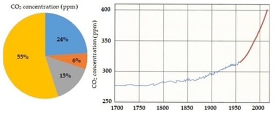
Figure 1.
The pie chart shows the volume percentage for each of the various GHG. The graph shows carbon dioxide concentration in the atmosphere over time, from Scripps Institution of Oceanography, 2015. Ice-core data were used before 1958, and Mauna Loa data after 1958 [8].
The reason why CO2 emissions have become a significant problem is visible in both the above charts from Figure 1. The largest share of greenhouse gases is CO2, and the atmospheric concentration of this gas started to increase rapidly during the human industrialization era. As CO2 absorbs and emits infrared radiation, this and other greenhouse gases trap the sun’s warmth over the earth’s surface—this is known as global warming [7]. CO2 is the GHG that is currently the key to stopping the process of global warming, and its emissions can be influenced by using alternative fuels for internal combustion engines.
2. Materials and Methods
This article presents information on the most important achievements of alternative fuels in terms of reducing exhaust emissions in modern and future RCCI dual-fuel engines. Information sources were analyzed to document the possibility of using low-emission fuels in dual-fuel combustion engines and the ways in which these fuels can be most effectively. This paper presents the reasons for limiting the emissions of exhaust gas components, such as carbon dioxide, methane, and nitrous oxide, and their impacts on global warming, which are well-known and widely described. The types of internal combustion engine which allow the use of the mentioned fuels and output the least of the harmful exhaust components have been reported. It is an analytical work based on the state of knowledge available at the moment. The researchers used scientific publications, books, conference materials, university multimedia presentations, scientific search engines (Research Gate and Google Scholar), and reports and studies made for companies. We also paid attention to popular science sources concerning this issue. A detailed list can be found in the bibliography.
3. Results
3.1. Biofuels and Alternative Fuels for Internal Combustion Engines
The fuel resources, fuel conversion technology, fuels themselves, and applications of them are shown in Figure 2, which should be treated as an introduction to the following analysis.
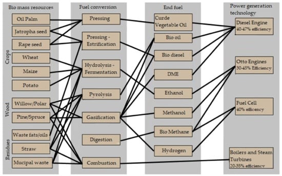
Figure 2.
Alternative fuels for internal combustion engines presented by manufacturer Wartsila in [7].
Liquid fuels are used for the primary fueling of classic diesel engines. Popular fuels used to power diesel engines are diesel oil and biodiesel. Oils of vegetable origins are distributed in mixtures with petroleum (hydrocarbon), making diesel fuels. Alternative fuels are created to reduce GHG emissions and exhaust components resulting from the combustion process. The alternative fuel (biofuel) production process may be based on partial recirculation of the carbon that is in the natural cycle. This strategy is based on plant-based products that, as they grow, take carbon dioxide from the atmosphere for their growth. By storing the carbon contained in atmospheric CO2, they eliminate some of it from the atmosphere. If exactly the same amount of CO2 is later emitted into the atmosphere as a result of the combustion of the fuel obtained from these plants, it is possible to speak of full CO2 recirculation. This is one of the main reasons scientists are trying to use biofuels in industry, energy, and transport. The second important factor is the limited amounts of non-renewable energy resources. The emphasis is on making them last by reducing energy consumption and replacing them with alternative energy sources. As a condition for access to the market in the European Union, biofuels must meet statutory requirements regarding sustainability—including cultivation—to receive certification. These requirements are enshrined in the EU directive 2009/28/EC which regulates the “Promotion of the Use of Energy from Renewable Sources.” These also include proof of greenhouse gas reduction, production which had to be reduced by 50% by 2018. In Germany, in the meantime, the average reduction of GHG production is about 70%. The transport sector and agriculture are being challenged to contribute to GHG reduction, partly as a result of the decisions of the climate protection agreement in Paris. In addition, rising fossil fuel prices, along with national tax advantages and biofuel quotas, favor a growing global demand for biofuels. Currently biodiesels are mainly used in diesel fuel/biodiesel blends, but also as clean fuels in Europe and many other non-European countries, such as the USA, Mexico, Brazil, Argentina, Malaysia, and Indonesia [9].
Biofuels can be classified on the basis of the quality requirements that are set in a given country for liquid biofuels [10].
Polish domestic biofuels for diesel engines can be classified according to their origins. They can be produced from methanol (FAME), ethanol (FAEE), or RME (rapeseed oil). The biofuels available in Poland for diesel engines are diesel fuels containing 20% biofuel produced from rapeseed oil or methanol. Pure methanol is not a desirable engine fuel on its own, due to its properties and the products of its combustion, but it is a desirable additive for other fuels. Details of the fuels’ properties are included in the regulations in Poland [10]. An interesting alternative in the context of bi fuels is hydrotreated vegetable oil (HVO), which is gaining popularity [11]. Biofuels can be manufactured all over the world with many different plants and fruits. Figure 3 shows the global biooil production in millions of tons per year, from the most commonly used plants.
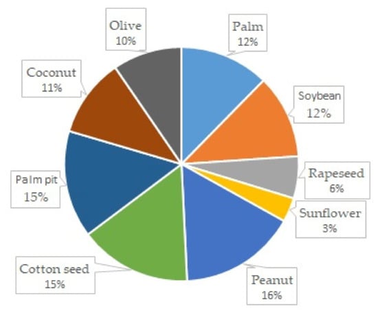
Figure 3.
Global biooil production in millions tone per year [12].
Both gaseous and liquid biofuels are commonly produced from many sources, and the examples from the Polish market presented above constitute only a small portion of the global variety of sources from which biofuels are produced today. There is widespread research on the possibility of using oils of biological origins [13]. Such sources of their origins, given by [14], include oils made of pongamia [15], algae [16], jatrophy [17], rice [18], mushrooms [19], coffee grounds [20], palm trees [4], coconuts, peanuts, soybeans, linseeds, and olives [12]; animal fat and sources of waste [21]; plastic [22]; used tires [23] and other rubber products [24]; used oil [25], especially used engine oil [26], transformer oil [27] and vegetable oil and sunflower oils [28]; municipal sewage [14]; and intermediates from various technological processes, such as pyrolytic oil [29]. The plants and fruits most commonly used to produce biofuels are shown in Figure 4. The chart also shows the production efficiencies of individual plants and fruits per hectare. This parameter is very important for potential usage of a given plant as a raw material for the production of diesel biofuel.
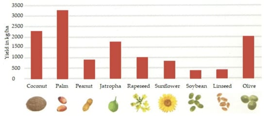
Figure 4.
Annual yields of different liquids of biological origins [12].
In addition, alternative diesel fuels are made of ethanol [30] or coal [31]—coal to liquids (CTL)—or synthetically [32,33]. Both natural gases and purified and methane-enriched biogases can be changed into liquid fuels—gases to liquids (GTL)—but changes of this type are associated with increases in the total emissions of well-to-wheels greenhouse gases (WTW GHG) compared to the original compressed natural gases (CNG). However, the emissions of WTW GHG are lower than those of the conventional fuel for diesel engines, that is, diesel, but the methodology for calculating this value in relation to this fuel is still limited due to difficulties in quantifying potential products that could be replaced by GTL. “[The] GTL pathway has been limited until now because of the difficulty in quantifying potential products to be displaced by GTL coproducts” [34]. For these reasons, the analysis in this article covers fuels that are not subject to such transformations. Due to the ease of obtaining them and their ecological value, biogases are desirable fuels. When purified and enriched with methane, a biogas can be directed to gas network installations; compressed and stored in cylinders; or burned in cogeneration installations with simultaneous production of heat and electricity, or in gas boilers. It should be remembered that the main difference between a biogas and a natural gas is the methane content. In order to achieve the caloric parameters in line with the standards of gas injected into the natural gas network, such as the heat of combustion and the Wobbe index, it is necessary to pre-purify agricultural biogas and to enrich it with methane [35]. Biogases, similarly to biooils, can be produced from various types of biological and waste products [36]. The chemical composition of a biogas strongly depends on the source it comes from. It often contains significant amounts of hydrogen, which translates into lower CO2 emissions in the combustion process, but any crude biogas also contains many ballast components, such as nitrogen and carbon dioxide, which must be removed in the cleaning process in order to use the biogas in an internal combustion engine.
3.2. Description of a Dual-Fuel RCCI Engine
Even when modern and equipped with the best exhaust gas cleaning systems, internal combustion (IC) engines always emit undesirable exhaust components. Figure 5 shows a typical pie chart of the exhaust gases emitted by marine engines.
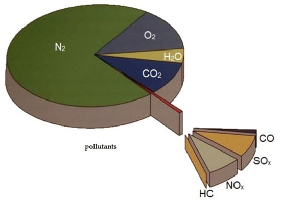
Figure 5.
The typical exhaust gases emitted by a modern, marine diesel engine [8].
Intuitively, there is a strong correlation between exhaust gas composition and the type of fuel used in the engine. The basis for multi-fuel combustion is the use of modern diesel engines that allow low-temperature combustion.
Combustion of fuels in internal combustion engines is based on the use of one type of fuel which is ignited either by forced spark ignition (SI) or by compression ignition (CI). The highest efficiency is currently achievable thanks to the ignition of a homogeneous air–fuel mixture in homogeneous charge compression ignition (HCCI) engines, where the ignition of all the fuel in the combustion chamber occurs simultaneously. This combustion takes place at a lower temperature than in a classic diesel engine, which leads to lower heat losses and the formation of less NOX, which translates into higher thermal efficiency for engines with this type of ignition. To achieve ignition in the combustion chamber of the engine, very specific (and difficult to achieve) conditions are required. Effective control of the moment at which ignition takes place in all areas of the engine operation is hard to achieve. For this reason, one of the variants of engines with this type of ignition method, which has great potential for use today, is an engine powered by two fuels with an ignition method called reactivity controlled compression ignition (RCCI).
RCCI is an ignition method in which highly reactive fuel is injected directly into the cylinder. It mixes with the air and self-ignites, thereby initiating the ignition of poorly reactive fuel, which is delivered via indirect injection to the combustion chamber earlier in the process. The same method of fueling the engine characterizes the classic dual-fuel engine, in which the fuel–air mixture is not homogeneous. Nowadays, every dual-fuel engine that is being developed allows the formation of a homogeneous air–fuel mixture in it. Figure 6 shows a schematic of classic dual-fuel injection system.
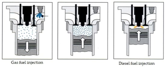
Figure 6.
Schematics of a direct dual-fuel injection process (prior injection of the poorly reactive fuel) [8].
A different fueling strategy using these types of fuels is called direct dual-fuel stratification (DDFS)—the difference is the use of direct injection for both fuels used in the engine [37]. Direct injection of two fuels requires the use of several injectors or a special injector, such as the product offered by Westport corporation [38], which has been mentioned in all relevant publications covering dual-fuel engine solutions [39]. A schematic of DDFS is shown in Figure 7.
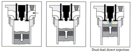
Figure 7.
Schematics of direct dual-fuel injection (both fuels injected directly) [8].
An engine powered by dual-fuel CNG/diesel requires only the already mentioned pilot dose of diesel fuel to initiate the ignition. When using a gaseous fuel as an additional poorly reactive fuel, it might be necessary to increase the amount of diesel fuel injected due to the insufficient resistance of the additional gas fuel to knocking combustion. The occurrence of knocking depends on many factors, but mainly the type of fuel and the compression ratio in the engine. Knocking combustion causes the formation of uncontrolled foci of fuel self-ignition, which hinder the proper course of the combustion process and the operation of the internal combustion engine. Its presence determines the impossibility of using certain fuels in an engine and the level of acceptable substitution of the basic fuel. The Figure 8 shows a diagram of the power supply and ignition in an RCCI engine powered by a mixture of CNG and diesel.
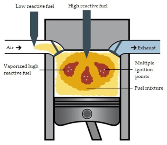
Figure 8.
Ignition and combustion in an RCCI engine; custom artwork based on [40].
High octane poorly reactive fuel (gasoline, alcohol, CNG, LPG, HCNG, biomethane, and other fuels) in an RCCI engine is delivered with air by the engine intake system. A premixed form of poorly reactive fuel is compressed and mixed with air to form a combustible air–fuel mixture. Thanks to its high resistance to auto-ignition, this mixture will not ignite despite the high temperature and pressure inside the cylinder. Reactive fuel is injected near the top, dead center with respect to the piston. The fuel must have good self-igniting properties, including a low flash point and the possibility of large atomization of the fuel during the injection process. The ignition of highly reactive fuel initiates ignition of the air housed with poorly reactive high octane fuel. The keys to controlling the moment of ignition and the course of combustion of the fuels used in the engine is the injection time and the properties of the reactive fuel, hence the name of this method of self-ignition. Depending on the stratification and the degree of mixing of the high octane fuel with air, the course of its combustion can be characterized in various ways, which is often a key issue in RCCI combustion studies. The amount of a given type of fuel depends more than anything else on the load on the engine and the fuel injection system. Figure 9 shows a chart with the dependence of the engine load on the possibility of using both fuels in different proportions. These proportions also determine the value of the replacement coefficient, which in the case of a classic compression ignition engine converted into a dual-fuel engine, says that about the amount of basic fuel (diesel) could be replaced by the added fuel (gas). The formula for the mathematical representation of this value in classic fuel supplied dual-fuel engines (the result of this formula is the ratio of energy basis) is presented below:
where mp and md indicate the mass flow rates of premixed, low reactivity, port injected fuel (PFI) and directly injected (DI) high reactivity fuel, respectively; hp and hd are the lower heating values of the PFI and DI fuels [41].
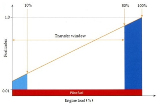
Figure 9.
An engine fueling window. Red represents the engine pilot fuel injection is taking place. Light blue shows that the engine can be started in gas mode, synchronized, and loaded—the engine will move to a back-up fuel after a time, if the engine load is not increased enough to get out of this area. Dark blue means that this engine is able to run an up to 100% load on either fuel, but transfers from liquid to gas are not permitted above 80% load—transfers from gas to liquid are permitted at any load. The higher the fuel index, the more liquid fuel required [42].
Once a homogeneous mixture of gaseous fuel is formed with air, the fuel can also self-ignite by a rapidly burning (pressure build-up) highly reactive fuel. Biofuel alcohols contain, apart from hydrogen and carbon, oxygen, which reduces the energy density of the fuel, but may facilitate the formation of a homogeneous mixture in the combustion chamber. Many biofuels (including HVO) contain alcohols in their structures. This points to the legitimacy of using these fuels in RCCI engines [6].
Thanks to the use of a poorly reactive fuel, homogeneously mixed with air, the efficiency of using the chemical energy contained in the fuel is increased. Its growth is also influenced by the uniform temperature distribution in the combustion chamber. This reduces the total amount of heat passing through the cylinder walls and prevents hot spots from forming in the cylinder. This is clearly shown in Figure 10. The maximum combustion temperature in the combustion chamber is lower than in conventional compression ignition engines.
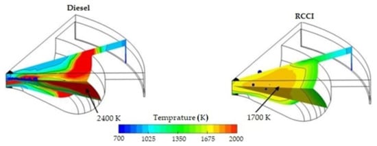
Figure 10.
Temperature distribution in the combustion chamber of an RCCI engine powered by CNG and diesel fuel, and in a classic diesel engine powered only by a diesel fuel [6].
Due to low-temperature combustion process, emissions of nitrogen oxides, solid particles, and soot are reduced, just like in the classic HCCI engine. Minimizing the emissions of some harmful exhaust components usually goes along with increasing the emissions of others, such as NOx and the soot, CO, and THC group. The results of the emission levels for RCCI engines depend on the type of engine, types of fuels, fueling strategies, types of engine modifications, and the emissions focus on. For example, researchers in [41], while focusing on measuring the levels of NOx and soot emissions, showed a very strong correlation between the emissions of these two substances. High flame temperature is one of the main factors causing the formation of nitrogen oxides during the combustion process. For this reason, nitrogen oxides are not commonly formed in RCCI engines as intensively as in a classic diesel engine. Another cause is the fuels having the stoichiometric compositions. The amounts of oxygen and nitrogen in the combustion chamber during the process are therefore reduced compared to a classic diesel engine. However, with higher loads and a high degree of fuel exchange—close to the maximum—and when the EGR system is not used—which inevitably results in an increase in the combustion temperature—there will be a significant increase in NOx emissions, but allowing for sufficiently effective THC afterburning noticeably lowers soot emissions, practically to zero [41].
It is extremely important during RCCI engine tests to check what modifications and what ways of fueling the engine have been applied in experiments. After creating an effective dual-fuel supply system, the most important modifications are the geometry of combustion chamber and shape of DI fuel injector. Researchers have shown that piston bowl geometry changes are the most important modifications in the conversion of a classic diesel CI engine to an RCCI engine. Some have created their own piston modifications for existing engines [43,44] using advanced simulation software, such as computational fluid dynamics (CFD), in order to optimize the final shape. Figure 11 shows some changes that can be made to an existing piston bowl.

Figure 11.
Cross-sectional views of the stock (left),) and bathtub (right) piston bowl geometries [43].
The form of combustion chamber in an RCCI engine is fundamentally different than in a classical CI diesel engine. The swirl ratio of the air–fuel mixture must be higher and the surface of the combustion chamber should be far smaller. This method of combustion of the air–fuel mixture necessitates flame propagation throughout the entire space above the piston. It also reduces the heat transfer surface, which leads to reduced thermal losses of the engine and an increase in its thermal efficiency. Changing the geometry of the combustion chamber inside the piston also allows one to easily change the compression ratio in the engine. Compression ratios can be 14.9:1, 16.1:1, or 18.7:1 because different piston bowl geometries have different effects on combustion [45]. Each of these compression ratios translates into a different piston shape and requires changes to the reactive fuel injection system. Researchers have created pistons for compression ratios 14.4:1 and 11:1 [43]. The effects of these changes are clearly visible in the emissions of harmful exhaust components and overall engine performance. Two groups of researchers collaborated to propose a piston bowl for an RCCI engine with a 15.3:1 compression ratio in exchange for the 17.5:1 stock engine [42]. This simple change had a significant impact on the engine’s operating range, allowing it to be used as an RCCI engine. Figure 12 shows charts of injection-combustion strategies for two different compression ratio options.
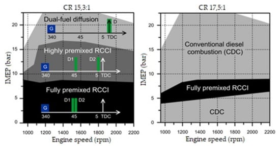
Figure 12.
Injection-combustion strategies used for a dual-mode engine: dual-mode RCCI/CDC (left) and a dual-mode dual-fuel (right) [46].
The graphs above show an increase in the range in which it is possible to operate the engine in dual-fuel mode, along with a reduction in the compression ratio. However, in addition to reducing the compression ratio, the researchers significantly changed the shape of the piston, allowing the engine to run on both fuels simultaneously throughout its entire operating range. This change is shown in Figure 13.
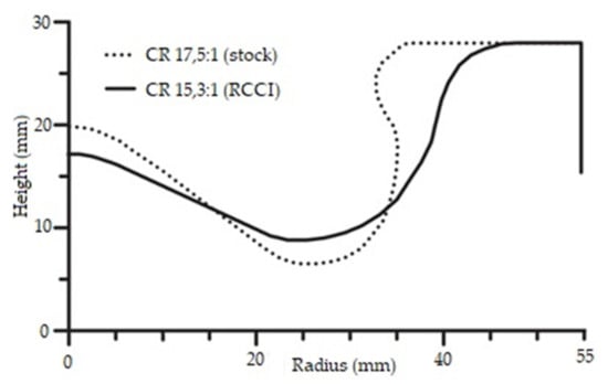
Figure 13.
A cross-sectional view of the stock and RCCI piston bowl geometries [46].
Some researchers changed the compression ratio of an engine without significantly modifying the shape of the combustion chamber itself, which is classically located inside the piston crown. The compression ratio values adopted for the designed pistons were 16.5:1, 15.5:1, and 14.5:1 [47]. This made it possible to study the influences of the compression ratio itself on the performance and emissions of dual-fuel engines without any influence from the shape of the combustion chamber itself. The effects of the changes presented by the researchers were visible in the emissions of all harmful exhaust components. It was shown that the emissions of MHC and particulate matter PM10 decreased as the compression ratio in the engine decreased. There were slight increases in CO and NOX. However, these changes were not significant. This study also focused on the impact of the compression ratio on the CO2 emissions, as shown in Table 2 (reproduced).
Table 2.
A comparison of NEDC estimations of FC, CO2, CO2 equivalents, and global cycle rp at different compression ratios [47].
The data above clearly show that the engine compression ratio has no influence on greenhouse gas emissions. The authors themselves drew this conclusion: “The DF CO2 saving over the test cycle are completely attributed to the intrinsic H/C characteristics of methane fuel; The GHG potential increase passing from diesel to dual-fuel mode due to the MHC emissions, the DF-CO2 equivalent calculated by means of the NEDC estimation increase of about 22% compared to diesel mode. In order to have the same GHG impact of diesel mode a global reduction of MHC emission (about 65%) is required.” The effect of the compression ratio, in the absence significant changes to the shape of the combustion chamber, is not a sufficiently important issue in dual-fuel engines to be considered high-priority among the necessary engine modifications. Nearly a decade ago, researchers optimized the geometry of the combustion chamber in the RCCI engine, along with its compression ratio and the shape of the direct fuel injector [48]. These optimizations are necessary for the RCCI engine to efficiently convert fuel to mechanical energy. It was clearly indicated that the effect of the swirling of the air–fuel mixture in a classic diesel engine does not translate to dual-fuel engines, which is well illustrated by the sharp edges marked in the upper part of the piston shown in Figure 14. Changing the shape of the piston also requires adjustment of the shape of the highly reactive fuel injector, which should be adapted to the other modifications in order to be able to achieve optimal combustion of the fuel–air mixture, leading to minimization of CO2 emissions in these engines.
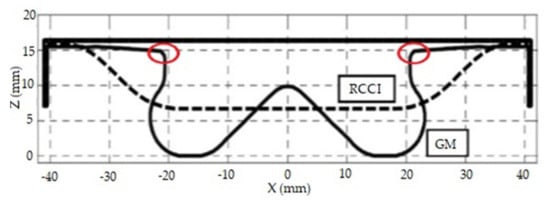
Figure 14.
A comparison of RCCI and classic CI engine pistons with a combustion chamber inside each [46].
In the figure above, the edges marked in red circles are the most important parts of the piston, which lead to the formation of turbulence in the fuel–air mixture. In the case of CDC, their use is necessary for proper combustion and ignition. Figure 15 shows examples of the shape of the injector used in a classic compression ignition engine. Clearly, only the shape shown in the left part of the figure could be used in an RCCI engine, in which the ignition of the fuel–air mixture should occur in all of the space above the piston as simultaneously as possible.

Figure 15.
A comparison of the combustion process in the CDC for different shapes of piston crown [7].
The shape of piston that is optimal for working in an RCCI engine is shown in Figure 16 [46]. The differences in the shapes of the two pistons show the significance of injection of the fuel directly into the combustion chamber.
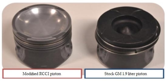
Figure 16.
A comparison of RCCI and classic CI engines made for dual-fuel research [46].
It should be mentioned here how important in the development of RCCI engines are the tests carried out with changes in the various types of fuels used. Scientists conducting this type of research should be commended. However, despite the significant contributions to the development of this field of science, this type of research has been carried out mainly in dual-fuel engines that do not use the alternative fuels with the greatest potential to reduce carbon dioxide emissions. It will be possible in the future to conduct further research with the use of other types of fuels described in this article.
Shape changes to the fuel injector and other parameters of RCCI engines are potential sources of advancement for modern single-fuel diesel engines, which are powered in a similar way to dual-fuel engines. Part of the fuel is added to the cylinder before the fuel–air compression stroke. Such engines operate on the basis of premixed charge compression ignition (PCCI) [49], where the already pre-stratified mixture is ignited. Developments in these engines are related to the developments in RCCI engines, because designers have to face similar problems and introduce solutions for the same elements. For PCCI engines though, the problems are centered on the use of one type of fuel, as it is difficult to create an engine that works efficiently on this principle. The possibility of using two independent fuels that fulfill different functions in the combustion process gives an advantage to RCCI engines that constitutes their superiority to other engines that use low-temperature fuels. Both of these solutions allow for an effective reduction of CO2, soot and NOX emissions. However, dual-fuel engines extend the range of fuels that can used to the entire range of fuels currently used in internal combustion engines, because they use the fuels intended for both CI and SI engines.
3.3. Hydrogen-Enriched Alternative Fuels
3.3.1. Pure Hydrogen as Fuel for IC Engines
Using hydrogen to generate energy reduces the level of environmental pollution released (and the degradation of the planet’s natural resources) if it is obtained from renewable sources. There are many methods of producing hydrogen, but if hydrogen is treated as a renewable fuel, it must come from a renewable source. It means that its production cannot involve the consumption of other fuels included in the group of non-renewable energy sources [50].
When hydrogen is burned, the energy of hydrogen’s chemical bonds is converted into thermal energy, and then into mechanical energy. Currently, there are solutions that allow the electrochemical energy of hydrogen to be produced by the combination of oxygen and hydrogen. Then, for its use, an electric motor is used connected to a fuel cell running on hydrogen or a fuel rich in hydrogen. This solution, known for decades, has not been popularized (despite being an attractive option for cars powered by electrochemical batteries) due to the low availability of fuel cells as a result of the high prices of the raw materials needed for their production, and above all, the problems related to the distribution and storage of hydrogen [51].
To use hydrogen generated by renewable energy sources in internal combustion engines, the most effective strategy is to mix the hydrogen with other fuels and co-combust them.
Hydrogen as the basic fuel for internal combustion engines has not been widely used and does not have a wide distribution network. Unlike natural gas, which is widely available in virtually every country in the world, hydrogen is currently available only in a small number of places. The solution to this problem turned out to be Hythane, in which hydrogen is co-distributed with natural gas. This mixture can use the natural gas distribution infrastructure without any modifications.
3.3.2. Hydrogen and Methane as Fuels for IC Engines
Hydrogen, just like natural gas, is called a cryogenic liquid because its liquid phase is below 200 K (−73 °C). Under atmospheric conditions, hydrogen is present as a gas. For storage, it must be kept under pressure or in cryogenic conditions. However, its liquid phase has a very narrow temperature range (only 6 degrees Kelvin), and it has a low boiling point, which makes it difficult to store in a liquid form. Increasing the pressure under which liquid hydrogen can be stored will not significantly increase the boiling point, because at just 13 MPa it will approach the critical temperature. The density of gaseous hydrogen increases with pressure slower than it would appear from the ideal gas equation.
Many alternative fuels contain hydrogen. Natural gas has the highest ratio of hydrogen to carbon among all hydrocarbon fuels. Natural gas (NG) is distributed for internal combustion engines in several forms. The most popular are compressed natural gas and liquified natural gas (LNG).
NG as a fuel for internal combustion engines is considered an alternative to both CI and SI engines. NG used in conventional SI engines is not problematic in the context of interference with engine structure. On the other hand, a CI engine requires the addition of a spark ignition system, or co-combustion with some liquid fuel dedicated for a diesel engine.
Natural gas contains the lowest amount of carbon among all hydrocarbon fuels. It is a widely available fuel extracted from underground sources, just like oil. A comparison of their basic properties is presented in Table 3.
Table 3.
The properties of hydrogen and natural gas. The figures from two sources were used to construct the table [52,53].
Natural gas may significantly differ in properties depending on its degree of processing after its extraction. Properties that must be met by natural gas sold as CNG or LNG fuel are determined by the law in force in a given distribution area. Sheets of characteristics are available in each country where fuel is distributed. In the case of Poland, CNG and LNG have two independent fuel charters [54].
Liquid fuel based on natural gas, LNG, comes from many different sources and varies significantly in chemical composition. The Wobbe numbers (Wobbe index) among the LNG delivered to Poland from various countries may be in range of 54.22 to 56.86 for the upper Wobbe index and from 48.86 to 51.31 MJ/m3 for the lower Wobbe index. These depend on low heating value (LHV) and high heating value (HHV) of the fuel, which are 37.15–41.71 MJ/m3 (LHV) and 41.17–46.06 MJ/m3 (HHV) for LNG. In delivery systems, the upper index of the Wobbe number should be at minimum level of 45, and the maximum level 56.9 MJ/m3. Values for various countries are shown in Table 4. Interesting is that for Trinidad LNG fuel, the HHV is lower than the LHV for fuels from Oman, Australia, and Malysia. The Polish standard requires a minimal HHV greater than 34 MJ/m3, and an LHV not less than 31 MJ/m3. This shows how important in laboratory research it will be to determine the fuel source and its physicochemical properties [55].
Table 4.
Different sources of LNG fuel in Poland [55].
Many sources show different parameters and requirements for CNG fuel. For example, in [7], for LHV the minimal value is 31 MJ/nm3. That requirement is for a Wartsila ship engine, which can work in dual-fuel mode. HHV and LHV parameters are different for gases from different countries: Groningen NG from the Netherlands has an HHV equal to 35.1 MJ/m3 and an LHV equal to 31.6 MJ/m3. Ecofisk NG from Norway has an HHV equal to 44.0 MJ/m3 and an LHV equal to 39.8 MJ/m3. Danish Gas from Denmark has HHV equal to 46.2 MJ/m3 and an LHV equal to 41.7 MJ/m3. Each country can pride itself on natural gas with unique physicochemical properties.
Table 5 and Table 6 show the chemical compositions of LNG fuel from similar countries as in Table 4. Differences are shown not only among different countries, but among data sources too.
Table 5.
Chemical compositions of LNG imported from various countries all over the world [56].
Table 6.
Chemical compositions of LNG imported from various countries all over the world [57]. Data for NG from Schrödinger, in the right column, are from [7].
Natural gas production (extraction) must also be accompanied by numerous processes for purification and enrichment, but the chemical compositions of natural gas from various sources still differ significantly [58].
Noticeable is that at that moment it is difficult to accurately define the chemical composition of natural gas applied as a fuel. That problem appears in every scientific attempt at having natural gas supply an internal combustion engine. Researchers in [57] presented the average CNG composition on the basis of information from many countries and sources, which is shown in Figure 17.
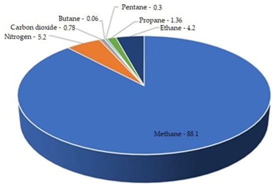
Figure 17.
The average chemical composition of CNG fuel [57].
The differences in the chemical compositions of gaseous fuels concern not only the processed natural gas but also the natural biogas itself.
The presented differences in LNG’s chemical composition and properties from various sources may facilitate the introduction of biogas (biomethane) into countries where regulations specifying the distribution of natural gas are not too restrictive. Such discrepancies do not normally occur with conventional engine fuels such as diesel and gasoline. Hence, the conclusion can be drawn that there is a greater potential for the production of biogas than biodiesel, due to the lower quality requirements that are currently imposed on it, that is natural gas, compared to diesel fuel.
Production of NG is increasing, and most countries do not allow its production to decline. Stocks of natural gas are greater than those of crude oil, so investing in clean combustion technologies for this fuel is a more far-reaching investment than in the case of classic liquid fuels. Figure 18 shows levels of production for NG. Such a far-reaching strategy for the use of fuel combustion technology also applies to hydrogen fuel and biofuels, which can be treated as renewable fuels for IC engines.
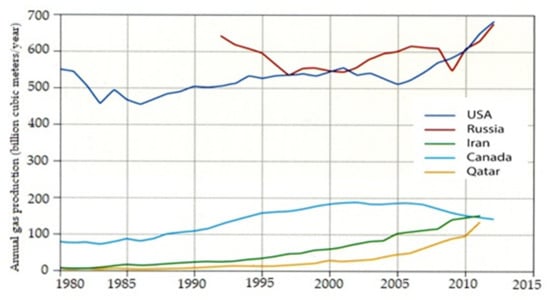
Figure 18.
The production of natural gas in different countries [7].
Natural gas mixes well with air, forming homogeneous mixtures. Due to the high activation energy, the laminar flame velocity of the gas–air mixture is lower than it is for other fuels. This is especially true when working with low to medium loads. This extends the combustion period, worsening the efficiency of the circuit. In addition, the extended duration of combustion means that when the exhaust valve is opened, both the pressure and the temperature of the exhaust gas are higher than when burning traditional hydrocarbon fuels. This is counteracted by using different values of the ignition angle, higher values of the compression ratio, and compact combustion chambers, which result in high swirling of the charge [6].
3.3.3. Hydrogen and Methane as One Fuel for IC Engines
Both natural gas and pure hydrogen can be stored in liquefied (LNG, LH2—liquid hydrogen) and compressed forms (CNG, CH2—compressed hydrogen), and in both forms it is possible to store them in similar types of tanks. However, their mixture stored in liquid form is not used. The proper name Hythane should be treated equally to the fuel known as HCNG. This nomenclature is related to the country of distribution. In the USA, this fuel is known as Hythane, and in Europe and Asia, HCNG. Its characteristic features include:
- -
- A high octane number;
- -
- Good ignition properties;
- -
- Wide flammability range and good diffusivity;
- -
- A high auto-ignition temperature at a low boiling point;
- -
- Low density and energy density;
- -
- The possibility of obtaining from processes other than crude oil processing.
In dual-fuel diesel engines, the level of replacement of diesel with natural gas CH4 is much higher than in the case of LPG, mainly due to the higher resistance of methane to knocking combustion and the higher calorific value of CNG [59]. The methane used as fuel is characterized by the highest octane number, reaching up to 130 octane. In the case of HCNG, this value will depend on the hydrogen content and whether the octane number is determined by the motor octane number (MON) or research octane number (RON). Hydrogen has an MON value of 70 and an RON value of 130; the octane values of methane are between 120 and 130. Generally, for gaseous fuels, it is assumed that the fuel resistance to knocking should be characterized by the value of the methane number, and not the octane number. Two extreme points have been adopted for LPG. Its value is considered to be 100 for pure methane and 0 for hydrogen. The higher the methane number value, the higher the fuel’s resistance to knocking combustion. Natural gas belonging to the H group should have a minimum methane number above 65 (16726: 2018). In [60], calculations were carried out, the results of which allowed them to state that, “Adding hydrogen to natural gas, in an amount that allows to maintain the physicochemical parameters of the gas specified in the relevant standards, reduces the methane number of the resulting natural gas-hydrogen mixture by a maximum of 22.1%. It should be added that in none of the analyzed cases the obtained methane number value was lower than the minimum value of 65. With regard to the optimal methane number value for gaseous fuels, it can be concluded that the addition of hydrogen to natural gas, while maintaining the assumptions made in the scope of energy parameters and gas density, may increase the knocking properties of the resulting mixture and contribute to the fact that it will not be an optimal fuel. The performed calculations and analyses also showed that the change in the value of the methane number of the natural gas-hydrogen mixture is proportional to the amount of hydrogen introduced into natural gas.” This means that the hydrogen content in the fuel will proportionally characterize the value of the methane number of the fuel, which in our case is HCNG.
Hydrogen, when co-fired with other fuels, will more completely combust than the other fuels. Its physical ranking gives it a strong possibility of combusting independently in a reciprocating engine. That idea has not been disseminated to this day, despite many attempts and much scientific research [50].
Hythane is far more promising. It is a mixture of CH4 and H2, and makes a number of interesting tariff lists for its designation as combustion fuel. Besides the fact that arc fired natural gas by the very nature of crude oil emits more CO2 than other hydrocarbons, it is possible to enrich natural gas with pure hydrogen. Such fuel is called Hythane, or HCNG, or H2CNG (compressed natural gas enriched with hydrogen). In [61], it was discovered, among other things, that the velocity of the laminar start-up of the methane–hydrogen mixture can be predicted with the square of the hydrogen proportion in the fuel. According to the research of some scientists, the fuel is most economical as a mixture of gas consisting of 11–36% hydrogen. As hydrogen content increases, the moment at which the reinforcement of the mixture is reached and the maximum pressure value in the polymer chamber is reached changes, which results in the need to create a map of the engine’s operation in order to test an engine operating with two types of methane fuel, CNG and LNG. Heat release and maximum pressure according to crank angle is shown on Figure 19. Hythane reduces fuel consumption and lowers CO, CO2, and NOX emissions, but also provides less power and torque. According to some researchers, the amount of primary HC emitted is unchanged.
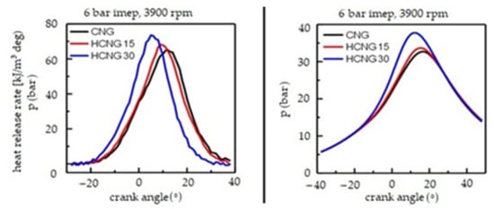
Figure 19.
Graphs of temperature and pressure during the combustion of CNG with different amounts of additive hydrogen [61]. HCNG15 fuel had 14 vol.% hydrogen, and HCNG30 29.7 vol.%. The energy content of hydrogen in such fuel is approximately 4.6% for HCNG15 and 11.4% for HCNG30.
The big advantage of HCNG is the possibility of their common storage, both in the vehicle and in petrol stations. Fuel enrichment to an appropriate level of hydrogen content can be carried out in regular CNG petrol stations, and deliveries of hydrogen fuel are not as frequent and expensive for petrol stations as with the sale of pure hydrogen [62].
In order for this fuel to meet certain safety standards, the ratio among the individual gases, although it may be variable (different), should not have above a certain concentration of hydrogen. The maximum ratio that is considered safe for this gas mixture is 1:1 (volume). In most European countries where it has already been legally regulated, HCNG may get up to 9% of its energy content from hydrogen, the same amount as natural gas in a transmission system. In the USA, Hythane contains approximately 20% hydrogen by volume. A higher concentration of hydrogen mixed with natural gas is currently difficult to distribute, due to the intense increase in the impact of hydrogen on steel, which was used to build the existing methane distribution network, and the metal parts of tanks and engines. A mixture of hydrogen and methane does not become highly explosive until it exceeds 50% hydrogen content. Based on the gas distributed in Europe, a value that is even slightly above 50% by volume of hydrogen can be assumed. Not exceeding this value prevents the occurrence of hydrogen disease, in which hydrogen molecules penetrate the walls of the materials they come into contact with, leading to their degradation, which occurs with steel [63].
It should be noted that as the hydrogen content in the mixture increases, the calorific content decreases, and yet the fuel consumption with a hydrogen concentration within a certain range is lower than for a gas containing almost only methane or a large amount of hydrogen. This shows very well how such fuel affects the economics of using the energy contained in it.
In Hythane, there are different numbers of hydrogen atoms per carbon atom, depending on the proportions of the gases. As the concentration of hydrogen in Hythane increases, the amount of carbon dioxide emitted decreases, but the actual emissions of WTW GHG depend on the method of producing mixed hydrogen, as shown in Table 7 [64].
Table 7.
WTW CO2 emissions (g/MJ) for HCNG produced by different means and with different hydrogen contents [64].
The combustion of fuels is always associated with the emission of substances into the atmosphere. In the case of GHG emitted by internal combustion engines, the three most common chemical compounds include carbon dioxide, methane, and nitrous oxide. These all contribute to the greenhouse effect. The amount of carbon dioxide emitted as a result of combustion of a given fuel is standardized for each country and precisely specified in the relevant documents. In Poland reports are prepared by government institutions [65,66,67]. These data are collected annually due to the Emission Trading System for CO2 emissions in force in the EU. Carbon dioxide emissions from natural gas combustion for 2017 were found in [65] to total 56.1 kg/GJ. In 2019 [66], the total was about 55.5 kg/GJ. In 2021 [67], the value of emissions is expected to continue to decline. CO2 emissions from biogas combustion totaled 54.6 kg/GJ; diesel oils, 74.1 kg/GJ; LPG, 63.1 kg/GJ; and petrol, 69.3 kg/GJ. The value for natural gas has changed over the years, in contrast to the other motor fuels mentioned here. This proves the significant influence of natural gas sources on its chemical composition, and the amounts of natural gas imported from particular sources differ from year to year. The lower emissions value for biogas proves the noticeable increase hydrogen content in this gas. In the case of HCNG—calculating it purely (strictly) proportionally—with a hydrogen content of 15% by volume, Poland could achieve CO2 emissions at a level close to the level of biogas CO2 emissions. With a hydrogen content of 30%, it would be possible to fall below this level. At 50% hydrogen by volume, the CO2 emissions would be reduced to the level of about 51 kg/GJ [68]. The changes in the thermal efficiency of the engine for different hydrogen contents in Hythane should be taken into account, and based on the analyzed test results, it can be assumed that the hydrogen concentration in HCNG should be in the range of a few to a dozen or so percent.
It should be noted that the emissions based on the method of fuel life cycle evaluation (WTW) for gas oil are the highest of conventional motor fuels, and its replacement by fuel such as HVO, CNG, or HCNG should be the highest priority for the internal combustion engine, to meet more ecological standards [69]. Carbon dioxide emissions from an engine operating on HCNG with different hydrogen concentrations, depending on RPM and the air to fuel ratio is shown on Figure 20.
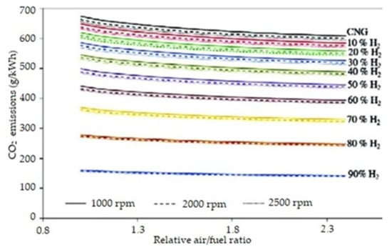
Figure 20.
Carbon dioxide emissions from an engine operating on HCNG with different hydrogen concentrations, depending on RPM and the air to fuel ratio [64].
A hydrogen and methane mixture (in addition to reducing GHG) significantly reduces the amounts of toxic exhaust components emitted as well. In many studies, combusting HCNG showed reductions in CO and NOX emissions. According to some research results, the emissions of HC compounds remained constant. When an engine with constant RPM was supplied with HCNG gas of various concentrations, an increase in NOx emissions was seen as the concentration of hydrogen in the fuel mixture increased [53]. The research in [70] also showed an increase in NOx emissions with an increase in hydrogen concentration in the gas mixture. Such results are obvious from the point of view of the physiochemistry of combustion, because it is very difficult to create a fuel that could reduce both the emissions of chemical compounds containing carbon and those containing nitrogen, because the mechanisms of their formation require opposite physical conditions. The issue of emissions of these compounds by HCNG-powered engines is currently the subject of research in many studies [71,72,73,74,75,76,77]. Worth noting is that the experimental values of NOX emissions are higher than the calculated values resulting from a simulation [72]. Figure 21 shows the NOX emission values that should theoretically occur in the Hythane combustion process under various engine operating conditions (A, B, C, D, E, F), modeled by various methods (models I, II, and III), and the experimental values which were recorded (experimental).
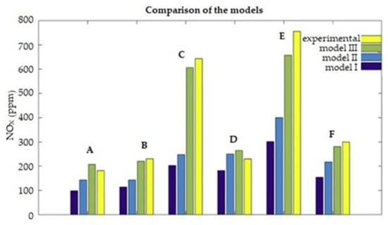
Figure 21.
The levels of NOX concentration in the exhaust gas determined on the basis of simulation models—models I, II, and III—and on the basis of the experimental results in various, established engine operating conditions, defined by the letters A, B, C, D, E, and F, signifying the concentrations of H2 in HCNG composition as follows: A—0% H2; B—5% H2; C—7% H2; D—10% H2; E—13% H2 [73].
The emission of other undesirable chemicals, such as HC, CH4, CO2, and CO, in most of the studies cited in this article, did not much changed or decrease the overall level of emissions. Emissions always depend on the degree of hydrogen enrichment, and not in a linear way.
During research on the effects of fueling an engine with HCNG gases of different compositions (from 0 to 13% hydrogen content) when using biofuel as the ignition initiating fuel, the lowest emission values of harmful exhaust components and the highest thermal efficiency were achieved with the use of HCNG containing 10% hydrogen [52]. Emission of CO2 was the lowest for the hydrogen concentration of 10%, which proves the high combustion efficiency of fuel of this composition. By comparison, HCNG with a hydrogen content ranging from 18 to 20% is used to power India’s public transport fleet [69]. Figure 22 presents the emissions of toxic exhaust components produced by methane fuel and Hythane, showing some of the benefits of using Hythane.
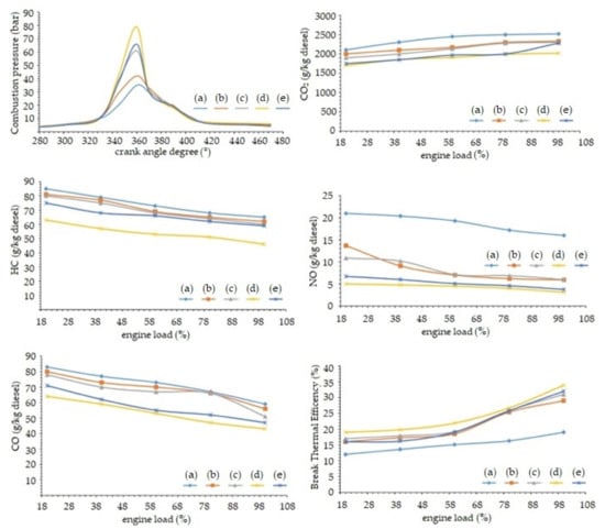
Figure 22.
Pressure, emission and efficiency of an engine fueled with HCNG fuel with the following composition: (a) —0% H2, (b)—5% H2, (c)—7% H2, (d)—10% H2, (e)—13% H2 with dual-fuel supply system [72].
3.3.4. HCNG Applications
There is a negative side of the popularity of alternative fuels such as CNG and HCNG: they are commonly portrayed as fuels only marked by superlatives. In many countries, such as India [64] and China [78], the implementation of these fuels for common use in automotive transport is very intensive, but knowledge about them is lacking, sometimes promoting false information about them.
Achieving low emissions requires significant interference in the design of the internal combustion engine, which must be preceded by research and optimization of the design for the combustion of a new type of fuel. In both single-fuel diesel engines and dual-fuel diesel engines (RCCI), it is necessary to adapt the combustion chamber to run on a new type of fuel. The shape of the combustion chamber in RCCI engines is very important for the formation of harmful chemical compounds contained in exhaust gases [6,79,80]. The degree of swirling of the air–fuel mixture changes, which makes it possible to completely burn the fuel. After installing the gas installation, engine operation should be optimized with the use of an engine dynamometer and an exhaust pollution measurement system (which is not always the case). Reducing carbon dioxide emissions when running on natural gas or Hythane does not always mean reducing GHG emissions. During the start-up of natural gas engines (CNG/LNG), in the case of unsuccessful ignition, methane is emitted in an amount related to the fuel consumption. Its emission during unsuccessful attempts to start the engine contributes to the overall CH4 emissions of the engine during its operation. This gas is 20 times more dangerous than carbon dioxide [7]. Much relevant data on HCNG combustion are still being gathered, but information about the differences in emissions among typical fuels is very popular, especially for dual-fuel engines. Table 8 shows the emissions of a typical, modern, medium-speed marine engine without an exhaust gas treatment system.
Table 8.
Emissions produced in the shipping industry: a typical medium-speed engine produced after the year 2000 without a post-treatment system. Emissions depend on fuel quality and engine type [7].
Researchers try to determine the speed of flame propagation in a combustion chamber (laminar burning speed correlations), which makes it possible to properly design the combustion chamber of an engine [81]. The influences of such obvious matters as the injection pressure of the pilot dose of diesel fuel on the BTE of the thermal efficiency of the engine are still being investigated [82]. This topic has been examined with different fuel injection angles and different combustion chamber shapes [6,79,80]. These parameters have the greatest impacts on the level of swirling of the fuel–air mixture, which for different fuel mixtures has different impacts on efficiency. The operation of an engine with HCNG fuel, compared to the use of a standard engine with a timing system (negative valve overlaps), designed for operation with conventional fuels such as diesel or gasoline, lessens the efficiency of using the alternative fuel, that is, HCNG, as shown in [83]. Only the effects of the use of a double pilot dose in dual-fuel engines have been investigated [84]. All of these factors affect the emissions of an engine powered by these fuels. Taking them into account should be an obligation when publishing any material related to these fuels and potential investments. The cost of such major engine modifications is many times greater than just supplying the engine with gas fuel and enabling its failure-free operation. Alarmingly high emissions of harmful exhaust components have been demonstrated in research [72]. The study [85] showed that the emissions of city buses converted to use CNG significantly exceed the assumed emission standards. The modifications to the engines are very often based on the conversion of a diesel engine to a petrol engine. It has been proven that the use of a laser ignition system in place of spark plugs allows one to increase the engine’s operating parameters, which proves the non-homogeneous combustion of the fuel–air mixture in diesel engines powered by such a gas [86]. The use of HCNG is possible in all applications where natural gas is used in compressed form. It is also possible when natural gas is doped with hydrogen at the stage of feeding the engine. In this case, it is possible to use LNG and enrich it with hydrogen. Most often, Hythane is used as a complete fuel, delivered and stored as is.
Adding hydrogen to natural gas at the stage of supplying the engine with both fuels is possible in cases where the hydrogen is stored independently as a second source of power, and when hydrogen is produced or supplied to the engine from another source. This can be achieved in stationary engines powered by natural gas from the municipal network and powered by hydrogen from self-production—for example, from industrial processes that are carried out locally (or produced from renewable energy sources). This would allow companies and industrial plants that use internal combustion engines to produce energy to reduce GHG emissions, which will help any such company’s reputation and provide the possibility of receiving subsidies for the development and construction of this type of installation. In the case of Hythane on ships, it would also be possible to transport both fuels independently (or to generate hydrogen onboard the ship), but the use of such installations will be justified when emission regulations begin to urge shipowners to reduce GHG emissions below a level which can be met by using Hythane to power marine engines. Natural gas transported on large ships is always stored in liquid form, in the form of LNG. This is because, in addition to the different condensation temperatures of methane and hydrogen, and their different densities which make it difficult to mix these fuels in liquid form, the problem is the very simple structure of hydrogen atoms, whose quantum properties have a large impact on their physicochemical properties. Hydrogen (H2) exists in two forms with slightly different physical properties. Molecules can exist in one of two forms—as orthohydrogen or parahydrogen. The form depends on the orientations of proton spins in the hydrogen atoms. The orthohydrogen molecules have parallel spins, whereas the spins of parahydrogen have antiparallel spins. In other words, in the orthohydrogen, the spins of the protons are in the same direction, and in the parahydrogen, the opposite. The chemical properties of both of these forms of hydrogen are the same, but they differ significantly in thermodynamic and physical properties. The contents of individual forms of hydrogen gas strictly depend on the temperature—the closer it is to absolute zero, the higher the content of parahydrogen. At room temperature, the orthohydrogen to parahydrogen ratio is already three to one. Table 9 clearly shows the differences in the physical and thermodynamic properties of different forms of hydrogen [50]. It differs significantly in density in various forms—pure parahydrogen has a density that is about 22% greater than that of hydrogen in the surrounding air. The specific heat of parahydrogen is also several percent higher, and the entropy of parahydrogen is less by about 9%. The other properties are similar to each other.
Table 9.
The physical and thermodynamic properties of different forms of hydrogen [50].
There are way of changing orthohydrogen into parahydrogen with the help of catalysts—paramagnetic ones—or it can be done by lowering the temperature of the hydrogen [87]. However, these are long-term processes, as a result of which heat is released (at the level of 527 J/g H2). The “instantaneous” condensation of normal hydrogen (75% orthohydrogen and 25% parahydrogen) would result in liquid hydrogen having the same proportions of both forms of hydrogen as in hydrogen under normal conditions. Only under the influence of long-term storage of hydrogen in liquid form would the ortho–para conversion take place spontaneously, and then the parahydrogen content would reach over 99.8% under the equilibrium conditions. The heat released changes with the temperature of the liquid hydrogen and increases as the temperature of the converting hydrogen decreases. Hence, difficulties in storing hydrogen in liquid form may arise, because the heat of hydrogen vaporization (447 J/g H2) at low temperatures is lower than the heat of ortho–vapor transformation and causes evaporation of condensed hydrogen and liquid losses, even in the best insulated tanks. Various types of catalysts have been used to convert orthane into parahydrogen before it is stored.
Installations of this type designed for the preparation of hydrogen for the purpose of storing it together with natural gas have not been described in scientific publications. Due to the problem of ortho–para hydrogen transformations described here, currently no technical solutions are used to prepare “HLNG” fuel for distribution.
3.3.5. Hydrotreated Vegetable Oil
Properties
Hydrotreated vegetable oil (HVO) is a form of synthetic diesel, an alternative renewable fuel for CI engines that is produced from vegetable fats and oils. Hydrogen in HVO production is used as a catalyst in the creation process instead of methanol in regular FAME biodiesel production. This makes HVO far more stable. In many ways, HVO is actually superior to other forms of fuel. Table 10 compares the different characteristics of regular diesel, FAME, and HVO biodiesel. HVO’s impacts on the exhaust emissions of these fuels are helpful. It has low solubility in water and the cetane number is high. Large differences between the cetane numbers of conventional diesel fuel and HVO would require some adjustments in the engine control to compensate for the fuel igniting earlier in the cycle, though this does not always happen. The lubricity is very low due to the absence of sulfur and oxygen compounds in the fuel; therefore, a lubricating additive is required [88]. The heating value per mass of HVO is higher due to the higher hydrogen content. The density is lower due to the paraffinic nature and the lower final boiling point. The cold properties of these fuels can also be controlled to meet the local requirements by adjusting the severity of the process or by additional processing. In any case, HVOs and paraffinic synthetic fuels will require good properties for a viable future, because fuel requirements set by legislation and fuel standards are becoming more stringent, due to new regulations for exhaust emissions, fuel economy, and onboard diagnostics [89].
Table 10.
The properties of diesel fuel components obtained from fossil and bio-renewable resources [88].
Table 11 presents a comparative effect of the use of HVO or FAME on the operation of a typical diesel engine. Virtually all operational factors favor HVO.
Table 11.
The influence of the type of biofuel on the operation of a diesel engine [88].
The biocomponents obtained in the process of hydroconversion (Figure 23) of vegetable oils and animal fats, known as HVO, are hydrocarbon paraffin fractions obtained as a result of the catalytic process of the hydroconversion of triglycerides of fatty acids present in vegetable oils and animal fats. If non-food or waste materials are used, they are classified as second-generation biomass components. Triglycerides can be divided into simple ones, containing three identical fatty acids, and complex ones, consisting of three different fatty acids. According to the presence of and number of double bonds, fatty acids can be divided into saturated, monounsaturated, and polyunsaturated [11]. The physicochemical properties of a triglyceride depend on the properties of the fatty acids, and in the case of complex triglycerides, on the relative positions of the individual acids in the triglyceride molecules. Saturated fatty acid triglycerides have high freezing points (above 30 °C) and better oxidative stability than unsaturated acid triglycerides, which are more reactive due to the presence of double bonds. The hydroconversion process of fatty acid triglycerides consists of three steps:
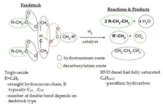
Figure 23.
Rapeseed oil’s hydroconversion process [90].
- Hydrogenation of double bonds in triglyceride hydrocarbon chains;
- Breakdown of the triglyceride molecule into propene and fatty acids;
- Decomposition of fatty acids into n-paraffinic hydrocarbon. Water, carbon dioxide, and carbon monoxide are produced; and propene is hydrogenated to propane.
Figure 24 shows the chemical molding process and composition of HVO.
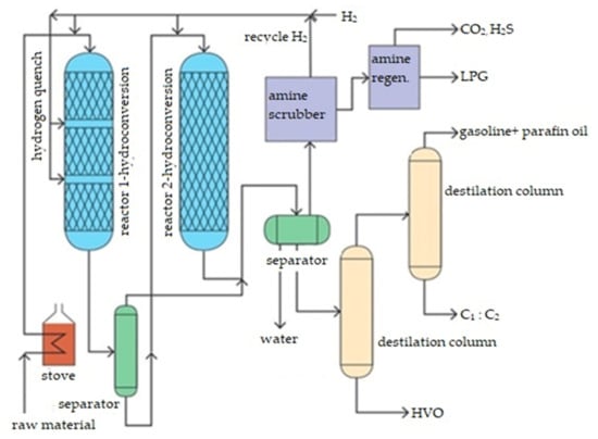
Figure 24.
The chemical formation and composition of HVO [11].
The pioneer in the research of the hydroconversion of vegetable oils and animal fats into hydrocarbon fuel components, and then in the commercialization of this technology on an industrial scale, was the oil company Neste Oil. In Finland, July 2007, the world’s first industrial site for the production of high-carbohydrate diesel biocomponents from natural oils and fats was commissioned, under the name NExBTL, with a production capacity of 170,000 tons per year. As a result of the development of this technology, the HVO process is offered by companies such as:
- Axens IFP (Vegan);
- Honeywell UOP (Ecofining—Green Diesel);
- Neste Oil (NExBTL);
- Syntroleum;
- UPM (BioVerno).
In total, the production capacity of the existing industrial HVO installations in the world exceeds 3 million tons per year.
Logistics and Storage Benefits
HVO, compared to FAME, retains very good properties in terms of storage capacity (Table 12). It is less hygroscopic, has no tendency to foam, relatively slowly decomposes, and has no tendency to form a sediment in storage installations.
Table 12.
Influences of the type of biofuel on the distribution and storage system [89].
GHG Emissions
Engine tests have shown environmental and performance benefits of hydrotreated vegetable oils as renewable diesel fuels.
Most of the studies available have shown that HVO usually leads to exhaust emissions benefits with normal engine performance. Substantial reductions in THC, NOx, CO, and HC emissions have been reported with the use of HVOs [88]. Official information from the Neste Renewable Diesel Handbook says that 90% of CO2 emissions are reduced when using HVO as opposed to regular diesel fuel [90]. Significant impacts on PM, HC, and CO engine emissions were observed by [89]. They reported the emission results with biodiesel, HVO, and regular diesel in engines tested in testbeds and city busses. In most cases, all regulated emissions, such as NOx, PM, CO, and HC, decreased with HVO compared to regular diesel, although an increase NOx was also observed [91]. According to another study [92] where exhaust emission tests were performed with different engine sizes (heavy trucks and passenger car engines), reductions of particulate mass, carbon monoxide (CO), and hydrocarbon (HC) emissions were noticed. A study by Soo-Young [93] in 2014 found that the use of HVO reduced NOx, PM, HC, and CO emissions without making any changes to the engine or its control. According to the study reported in [94], where exhaust emission tests were performed on heavy duty turbocharged diesel engines, average reductions in all emissions were clear. The most significant reduction of about 35% was measured in smoke. With HVO, emissions of NOx were reduced by about 5%. A reduction in specific fuel consumption by 5% was also noticed. Therein, the advantages of using HVO also appeared in relation to typical biodiesel. The study showed averages of all speeds and loads with default injection timing. Emissions of HVO and biodiesel compared with to normal diesel fuel are shown on Figure 25.
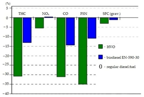
Figure 25.
Emissions of HVO and EN 590-30 compared with those of regular diesel fuel [94].
In general, most of the studies that examined HVO found it to be a fuel which can help to reduce GHG emissions. Another observation is that in most cases, HVO i=was examined under steady-state engine operation or in a vehicle, and as a result there is a lack of information from transient conditions, which are experienced for most of the operating life of vehicle. Furthermore, HVO was investigated in existing engines only, by changing the fuel. Default engine settings are not optimal for HVO combustion because of its slightly different properties.
There is also no information about the use of HVO as a pilot fuel in the context of dual-fuel systems. Of course, this should be investigated in the near future. Nevertheless, the available knowledge about HVO indicates that there is potential for the use of this fuel in the context of modern RCCI systems to reduce overall GHG emissions.
3.4. Hydrogen-Enriched Alternative Fuels—Summary
In RCCI engines, a high energy share of a poorly reactive gaseous fuel allows one to reduce exhaust opacity and reduce the emissions of harmful exhaust components, such as solid particles, NOX, CO, CO2, and NMHC [95]. As the engine load increases, the share of diesel fuel (HVO) in the proportion of fuels used increases. This leads to slight increases in the emissions of harmful exhaust components, but it also has an impact on the emission of carbon dioxide. The combustion of diesel fuel produces more CO2 than in the combustion of CNG [96]. The emission of many harmful exhaust components depends on the energy proportions of the fuels used in RCCI engines (it is possible to “control” the emissions). The introduction of appropriate settings for the operation of such an engine may decide whether or not to meet a specific exhaust emission standard, without physical interference in its construction.
In RCCI engines, despite the positive impacts of a high share of CNG or HCNG on CO2 emissions and some harmful exhaust components, too much of it in the combustion process leads to reductions in performance for the engine’s operating parameters. Figure 26 shows the operating parameters of the engine powered by both fuels at its maximum load compared to the engine operating only on diesel fuel [97].
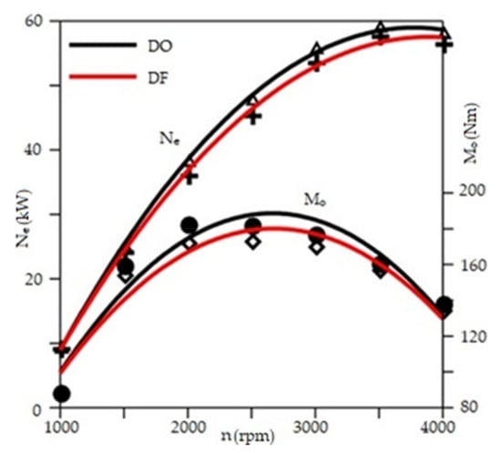
Figure 26.
Parameters of a CI engine powered by diesel fuel (black) or CNG and ON (red) with maximum output power and torque [97].
Tests were usually carried out on CNG and diesel fuels. This type of setup in RCCI engines is common in scientific works. Given the trend of reducing GHG emissions, it is advisable to carry out tests with this type of engine with alternative fuels that allow for the maximal reduction of CO2 emissions, and to check these fuels’ impacts on the operating parameters of the engine, because there are no studies available in the literature that would allow one to determine the impacts described in this article of fuels on the performance of RCCI engines.
4. Discussion
Certain considerations in the preparation of this article left the authors in doubt about several points, and we address them here.
The work [61] contains quite specific information on the combustion characteristics of hydrogen mixed with natural gas. It was an original work by one author, which is currently not available among the other works by this author. Other publications by this author, where he appears most often with other authors, do not in most cases concern the topics we discussed, and in the case of one topic related to HCNG, they did not present such bold theoretical theses, but numerical and empirical studies and their results. Although the author’s publication [61] was a source of very interesting data, we have some doubts as to the validity (2012).
Papers looking at specific results of tests on HCNG with a specific composition are very difficult to compare with each other. The composition of fuels should be determined by the regulations governing its chemical and physical parameters. In many countries, fuel such as HCNG is not registered, so there are no regulations governing its composition. The composition itself may therefore be determined by researchers in a way that differs from other researchers, and the method itself may not be disclosed, because showing all information in scientific works is neither recommended nor common practice. Supposed differences in the composition of HCNG gas, which theoretically can be compared with each other, may in practice turn out to be incorrect. For this reason, one should be very careful when comparing results from different papers.
As already described in detail in the article, natural gas itself can significantly differ in chemical composition depending on the source, and the creation of Hythane is based 100% on this base fuel. The problem with the formation of ortho- and parahydrogen in hydrogen fuel has also been described in detail; it also introduces some inaccuracies in the physicochemical parameters of the final fuel. The use of even chemically pure hydrogen can lead to the use of hydrogen with undesirable physical properties for a given application. Hythane is a fuel that not only widely used yet, and it is very strongly dependent on the “component fuels” that create it; therefore, its parameterization is a noticeable problem for researchers, so we are not convinced that the current information on the precisely parameterized composition of HCNG can be relied upon.
There is also a lack of studies in the scientific literature that describe the use of Hythane in a dual-fuel or RCCI engine. This also applies to the possibility of using HVO as a pilot dose. In the context of the HVO, its use in “dual fueling” was also not tested, and that should be done. In a dual-fuel system, the focus is on replacing liquid fuel with gas fuel as much as possible, so the issue of pilot fuel becomes secondary. Nevertheless, HVO should be examined in terms of its ability to initiate combustion in RCCI and the emissions it puts out in this mode of operation. This leads to the conclusion that despite the analysis carried out, further research is needed in regard to the use of this type of low-emission alternative fuel in high-performance dual-fuel engines. Studies heading in this direction can be found. Take [98] as an example: studies of an engine powered by HCNG and B100 fuel were performed. Additional research is still needed on this subject though. The existing research of this type could not always be linked with the research on emissions of exhaust gas components related to the issues of global warming.
Due to the lack of a sufficient amount of research of this type, we have decided to also support these efforts with significant research on fuels of this type in single-fuel internal combustion engines, and further research will allow us to conduct a far more in-depth analysis on this subject of interest.
Finally, it is necessary to mention the extensive bibliography related to the subject of the dual-fuel engine itself. There is a lot of information about it. Readers may find the references on this subject helpful, but because the subject of the RCCI engine itself is not the focus of this article, the items related to it have been limited to the minimum necessary, which proves the wealth of literature available on this subject [6,79,80].
N2O emissions are important for global warming, but the N2O concentrations in IC engines’ exhaust gases in comparison to CO2 concentrations are insignificant, and the number of researchers focusing on that topic is small. The greater problem is CH4, the emission of which is proportionally more common, and with the advent of new regulations limiting the emission of harmful exhaust components, compliance with them may become problematic when fueling an engine with fuel based on natural gas.
The latest Euro 7 scenarios assume the introduction of a limitation of methane in the exhaust gas, measured as a separate component of the exhaust gas. Its permitted emission level differs in the two main scenarios envisaged for the new Euro 7 standard. Table 13 and Table 14 show the emission limits for light and heavy-duty vehicles, taking into account Euro 6, which is already in force, and the two scenarios for Euro 7: A and B.
Table 13.
Euro 7 emission limits scenarios—LDV in mg/km, #/km [99].
Table 14.
Euro 7 emission limits scenarios—HDV in mg/kWh and #/kWh [99].
The predicted emission limit for methane is very strict and may prevent the use of CNG and LNG as standalone fuels, as many engines powered by these fuels may have serious problems with meeting such a stringent standard. Depending on which scenario is finally introduced by the EU, alternative fuels such as HCNG and HVO may have a significant impact on the possibility of meeting them, thanks to the possibility of effectively reducing greenhouse gas emissions caused by internal combustion engines.
5. Conclusions
Alternative fuels could be the key to reducing CO2 emissions and other greenhouse gases in the combustion process.
Researchers regularly write about the advantages of using hydrogen as a fuel for internal combustion engines. For example: “A hydrogen fueled internal combustion engine has great advantages on exhaust emissions including carbon dioxide (CO2) emission in comparison with a conventional engine fueling fossil fuel” [100]. One must bear in mind the difficulties of using it on its own. However, fuels rich with it enable reductions in CO2 emissions.
Both HCNG and CNG are commonly researched and used in IC engines. The amount of CNG research by far exceeds the amount of HCNG research, and the same is true of the number of applications in practice. Both of these fuels have shown high potential for reducing CO2 emissions in tests. HCNG has been more impressive, and CO2 emissions decreased with the content of hydrogen in the fuel. There is also a lack of widespread research on N2O emissions, which indicates further uncertainty about the climate impact of this type of fuel.
The studies that were successfully analyzed do not strictly concern the influences of the analyzed fuels on global warming. The works that treated the analyzed fuels as sources of power for dual-fuel or RCCI engines were also rare. In the case of the fuels selected by the authors, the co-combustion of which would have the greatest potential to reduce CO2 emissions, it was not possible to obtain a research paper in which both these fuels (HVO and HCNG) were used in RCCI engine emission tests. Despite the lack of consistent reference data, the overall picture of the knowledge available indicates the validity of further work in the context of RCCI with a dual-fuel supply of HCNG and HVO (as a pilot dose). All data on the emissions of the combustion of these fuels in mono-fuel systems report measurable benefits through reduced GHG emissions. Further work should be empirical, or measure engine performance and emissions on laboratory engine beds, in dyno testing, and in tests in real cars travelling in traffic.
We noticed a problem with the parameterization of the physicochemical properties of gaseous fuels. The spread between the various fuels is big; the problem is strongest for NG and HCNG fuels. Big differences in parameters are not only allowed by regulations. Large differences in the parameters of some fuels are not only allowed by the regulations, but also often in cases of new fuels, such as HCNG, are not covered by them at all. This is certainly a fact used by their producers. Even in research, there are noticeable differences in the chemical composition of different HCNG, which also did not agree with the theoretical calculations carried out by the author. For this reason, the properties of natural gas taken from one of the cited works were used in the Table 15 below.
Table 15.
Summary table with a comparison of important fuel parameters [11,66,67,68,101,102,103,104].
6. Final Summary Conclusions
- The aim is to minimize GHG emissions from internal combustion engines. Alternative fuels are being developed to reduce carbon dioxide emissions by reducing the amounts of carbon therein.
- RCCI engines, due to the specificity of their functioning, allow for very effective use of the fuels burned, while ensuring low GHG emissions.
- Gaseous fuels based on natural gas have very diverse chemical compositions, but show the greatest potential to reduce CO2 emissions. These fuels can be enriched with hydrogen, which further improves their emission properties. There are also highly reactive fuels (when used as pilot dose fuels), and hydrogen is used for refining them.
- There have been a very small number of empirical studies examining the feasibility of using low-emission fuels in RCCI engines.
- An issue worth discussing is the emissions of other greenhouse gases (N2O and CH4), on which should be focused by conducting further research and reviews in the context of the use of alternative hydrogen-enriched fuels in RCCI.
Author Contributions
Conceptualization, G.S. and M.K.; methodology, M.K., J.C. and G.S.; validation, M.K., J.C. and G.S.; formal analysis, J.C.; investigation, J.C. and G.S.; resources, J.C. and G.S.; data curation, J.C. and G.S.; writing—original draft preparation, J.C. and G.S.; writing—review and editing, J.C. and G.S.; visualization, J.C. and G.S.; supervision, M.K.; project administration, M.K.; funding acquisition, M.K. All authors have read and agreed to the published version of the manuscript.
Funding
This research was funded by the MILITARY UNIVERSITY OF TECHNOLOGY, grant number UGB 880/2021.
Institutional Review Board Statement
Not applicable.
Informed Consent Statement
Not applicable.
Data Availability Statement
The data presented in this study are available in in sources presented in References.
Conflicts of Interest
The authors declare no conflict of interest.
References
- Nova, I.; Tronconi, E. UREA SCR Technology for deNOx After Treatment of Diesel Exhausts; Springer Science + Buisness Media: New York, NY, USA, 2014. [Google Scholar]
- Djermouni, M.; Ouadha, A. Thermodynamic analysis of an HCCI engine based system running on natural gas. Energy Convers. Manag. 2014, 88, 723–730. [Google Scholar] [CrossRef]
- Pandian, M.; Krishnasamy, A. Comparison of different low temperature combustion strategies in a light duty air cooled diesel engine. Appl. Therm. Eng. 2018, 142, 380–390. [Google Scholar] [CrossRef]
- Tobib, H.M.; Rostam, H.; Mossa, M.A.A.; Hairuddin, A.; Noor, M.M. The performance of an HCCI-DI engine fuelled with palm oil-based biodiesel. In Proceedings of the IOP Conference Series: Materials Science and Engineering 1st International Postgraduate Conference on Mechanical Engineering (IPCME2018), Pekan, Malaysia, 31 October 2018; p. 469. [Google Scholar]
- Eldin, A.H.; Medhat Elkelawy, M.; Zhang, Y.-S. HCCI Engines Combustion of CNG Fuel with DME and H2 Additives; SAE International: Warrendale, PE, USA, 2010. [Google Scholar]
- Reitz, R.D.; Duraisamy, G. Review of high efficiency and clean reactivity controlled compression ignition (RCCI) combustion in internal combustion engines. Prog. Energy Combust. Sci. 2015, 46, 12–71. [Google Scholar] [CrossRef] [Green Version]
- Kuiken, K. Gas- and Dual-Fuel Engines for Ship Propulsion, Power Plants and Cogeneration. In Book I: Principies; Target Global Energy Training: Onnen, The Netherlands, 2016; pp. 1–488. [Google Scholar]
- Kuiken, K. Gas- and dual-fuel engines for ship propulsion, power plants and cogeneration. In Book II: Engine systems and environment; Target Global Energy Training: Onnen, The Netherlands, 2016; pp. 1–544. [Google Scholar]
- Requirements for Fuels for DEUTZ Engines. Available online: https://www.deutz.com/en/products/technology-solutions/fuels-of-the-future (accessed on 25 April 2021).
- ISAP. Rozporządzenie Ministra Energii z dnia 25 maja 2016 r. w sprawie wymagań jakościowych dla biopaliw ciekłych. Dziennik Ustaw, 3 June 2016; 771. [Google Scholar]
- Lubowicz, J. Impact of Bio-Component Obtained by the “Co-Processing” on Properties of Diesel Fuel; Oil and gas Institute National Research Institute: Kraków, Poland, 2016; p. 208. [Google Scholar]
- Klimstra, J.; Hotakainen, M. Smart Power Generation, 3rd ed.; Avain Publishers: Helsinki, Finland, 2011. [Google Scholar]
- Prakash, R.; Singh, R.K.; Murugan, S. Use of Biodiesel and Bio-oil Emulsions as an Alternative Fuel for Direct Injection Diesel Engine. Waste Biomass Valoris. 2013, 4, 475–484. [Google Scholar] [CrossRef]
- Wikipedia. Available online: https://pl.wikipedia.org/wiki/Biopaliwo (accessed on 10 December 2020).
- Gopal, N.K.; Karupparaj, R.T. Effect of pongamia biodiesel on emission and combustion characteristics of DI compression ignition engine. Ain Shams Eng. J. 2015, 6, 297–305. [Google Scholar] [CrossRef] [Green Version]
- Eloka-Eboka, A.C.; Inambao, F. Performance and Emission Profile of Micro-Algal Biodiesel in Compression Ignition Engine. Int. J. Eng. Res. Afr. 2017, 30, 110–124. [Google Scholar] [CrossRef] [Green Version]
- Himanshu, P.; Rajai, V.; Das, P.; Charola, S.; Mudgal, A.; Maiti, S. Study of Jatropha curcas shell bio-oil-diesel blend in VCR CI engine using. RSM 2018, 122, 310–322. [Google Scholar]
- Prabhahar, R.S.S.; Nagaraj, P.; Jeyasubramanian, K. Promotion of bio oil, H2 gas from the pyrolysis of rice husk assisted with nano silver catalyst and utilization of bio oil blend in CI engine. Int. J. Hydrogen Energy 2020, 45, 16355–16371. [Google Scholar] [CrossRef]
- Revanth, P.; Vemuri, B.; Sarma, V. Fungi as Promising Biofuel Resource. In New and Future Developments in Microbial Biotechnology and Bioengineering; Elsevier: Amsterdam, The Netherlands, 2019; Chapter 2; pp. 149–164. [Google Scholar]
- Uddina, M.N.; Techatoac, K.; Rasulb, M.G.; Hassanb, N.M.S.; Mofijurb, M. Waste coffee oil: A promising source for biodiesel production. Energy Procedia 2019, 160, 677–682. [Google Scholar] [CrossRef]
- Naima, K.; Liazid, A. Waste oils as alternative fuel for diesel engine: A review. J. Pet. Technol. Altern. Fuels 2013, 4, 30–43. [Google Scholar]
- Damodharan, D.; Kumar, B.R.; Gopal, K.; De Poures, M.V.; Sethuramasamyraja, B. Utilization of waste plastic oil in diesel engines: A review. Rev. Environ. Sci. Bio/Technol. 2019, 18, 681–697. [Google Scholar] [CrossRef]
- Islam, N.; Nahian, R. Improvement of Waste Tire Pyrolysis Oil and Performance Test with Diesel in CI Engine. J. Renew. Energy 2016, 2016, 5137247. [Google Scholar] [CrossRef] [Green Version]
- Lei, W.; Yun, W.; Jie, J. Pickling experimental study on preparation of diesel oil with pyrolysis oil from waste rubber. Environ. Technol. Resour. Proc. Int. Sci. Pract. Conf. 2017, 1, 169. [Google Scholar] [CrossRef]
- Arpa, O.; Yumrutas, R.; Demirbas, A. Production of diesel-like fuel from waste engine oil by pyrolitic distillation. Appl. Energy 2010, 87, 122–127. [Google Scholar] [CrossRef]
- Maceiras, R.; Alfonsín, V.; Morales, F.J. Recycling of waste engine oil for diesel production. Waste Manag. 2017, 60, 351–356. [Google Scholar] [CrossRef] [PubMed]
- Nabi, N.; Akhter, S.; Rahman, A. Waste Transformer Oil as an Alternative Fuel for Diesel Engine. Procedia Eng. 2013, 56, 401–406. [Google Scholar] [CrossRef] [Green Version]
- Pavani, A.; Hebale, A.; Poojary, V.; Parulekar, S.; Kiran, C.; Neeta, K. Waste sunflower oil as an alternative fuel for diesel engines. In Proceedings of the International Conference on Nascent Technologies in the Engineering Field (ICNTE), Navi Mumbai, India, 9–10 January 2015. [Google Scholar]
- Shihadeh, A.; Hochgreb, S. Diesel Engine Combustion of Biomass Pyrolysis Oils. Energy Fuels 2000, 14, 260–274. [Google Scholar] [CrossRef]
- Yue He, M.; Gao, H.T.; Liu, W. Thermodynamic Analysis of Ethanol-Diesel Oil and Waste Heat Recovery for Diesel Engines. Adv. Mater. Res. 2014, 1070, 140–145. [Google Scholar] [CrossRef]
- Chen, L.; Gao, K.; Zhang, C.; Lang, W.; Zhang, C. Alternative fuels for IC engines and jet enginesand comparison of their gaseous and particulatematter emissions. In Advanced Biofuels; Woodhead Publishing: Sawston, UK, 2019; pp. 17–64. [Google Scholar]
- Lotko, W.; Łodygowski, K. Fuelling compression ignitionengine by mineral dieselfuel mixture with synthetic hydrocarbons, Uniwersytet Techniczno-Humanistyczny w Radomiu. Arch. Automot. Eng. Arch. Motoryz. 2017, 75, 93–104. [Google Scholar]
- Dieselnet. Available online: https://dieselnet.com/tech/fuel_synthetic.php (accessed on 14 January 2021).
- Forman, G.; Hahn, T.; Jensen, S.D. Greenhouse Gas Emission Evaluation of the GTL Pathway. Environ. Sci. Technol. 2011, 45, 9084–9092. [Google Scholar] [CrossRef] [PubMed]
- Szołucha, M.M. Standaryzacja Biogazu do Jakości Gazu Ziemnego; Institute of Nuclear Chemistry and Technology,: Warsaw, Poland, 2015. [Google Scholar]
- Dağlıoğlu, S.T. Life Cycle Assessment for Biogas/Biomethane Production. In Proceedings of the 2nd International Eurasion Conference on Science, Engineering and Technology (EurasianSciEnTech 2020), Gaziantep, Turkey, 7–9 October 2020. [Google Scholar]
- Luong, M.B.; Sankaran, R.; Yu, G.H.; Chung, S.H.; Yoo, C.S. On the effect of injection timing on the ignition of lean PRF/air/EGR mixtures under direct dual fuel stratification conditions. Combust. Flame 2017, 183, 309–321. [Google Scholar] [CrossRef]
- Leclercq, N. Westport, Natural Gas Vehicle Technologies for Light, Medium, Heavy and High Horsepower Applications; GasShow: Warsaw Poland, 2013. [Google Scholar]
- Melaika, M.; Herbillon, G.; Dahlander, P. Spark ignition engine performance, standard emissions and particulates using GDI, PFI-CNG and DI-CNG systems. Fuel 2021, 293, 120454. [Google Scholar] [CrossRef]
- Engine Management Systems for CPBC and RCCI Engines. Available online: https://www.arenared.nl/cpbc+~+rcci (accessed on 21 March 2021).
- Fraioli, V.; Beatrice, C.; Di Blasio, G.; Belgiorno, G.; Migliaccio, M. Multidimensional Simulations of Combustion in Methane-Diesel Dual-Fuel Light-Duty Engines; SAE International: Warrendale, PE, USA, 2017. [Google Scholar]
- Kuiken, K. Gas- and dual-fuel engines for ship propulsion, power plants and cogeneration. In Book III: Operation and Maintenance; Target Global Energy Training: Onnen, The Netherlands, 2016; pp. 326–327. [Google Scholar]
- Benajes, J.; Garcia, A.; Monsalve-Serrano, J.; Boronat, V. Dual-Fuel Combustion for Future Clean and Efficient Compression Ignition Engines. Appl. Sci. 2016, 7, 36. [Google Scholar] [CrossRef]
- Curan, S.; Hanson, R.M.; Wagner, R.M.; Reitz, R.D. Efficiency and Emissions Mapping of RCCI in a Light-Duty Diesel Engine; SAE International: Warrendale, PE, USA, 2013. [Google Scholar]
- Splitter, D.; Wissink, M.; DelVescovo, D.; Reitz, R. RCCI Engine Operation Towards 60% Thermal Efficiency; SAE International: Warrendale, PE, USA, 2013. [Google Scholar]
- Garcia, A.; Monsalve-Serrano, J.; Roso, V.R.; Martins, M.E.S. Evaluating the emissions and performance of two dual-mode RCCI combustion strategies under the World Harmonized Vehicle Cycle (WHVC). Energy Convers. Manag. 2017, 149, 263–274. [Google Scholar] [CrossRef]
- Di Blasio, G.; Belgiorno, G.; Beatrice, C. Parametric Analysis of Compression Ratio Variation Effects on Thermodynamic, Gaseous Pollutant and Particle Emissions of a Dual-Fuel CH4-Diesel Light Duty Engine; SAE International: Warrendale, PE, USA, 2017. [Google Scholar]
- Hanson, R.M.; Curran, S.J.; Wagner, R.M.; Kokjohn, S.L.; Splitter, D.A.; Reitz, R.D. Piston Bowl Optimization for RCCI Combustion in a Light-Duty Multi-Cylinder Engine; SAE International: Warrendale, PE, USA, 2012. [Google Scholar]
- Torregrosa, A.J.; Broatch, A.; Garcia, A.; Mónico, L.F. Sensitivity of combustion noise and NOX and soot emissions to pilot injection in PCCI Diesel Engines. Appl. Energy 2003, 104, 149–157. [Google Scholar] [CrossRef] [Green Version]
- Surygała, J. Wodór Jako Paliwo, 1st ed.; WNT: Warsaw, Poland, 2008. [Google Scholar]
- Suki, W. Hydrogen Equipment and Solution; Chart Industries, Inc.: Ball Ground, GA, USA, 2020. [Google Scholar]
- Babalola, O.A.; Sanni, S.; Ibegbu, A.J.; Ameloko, A.A. Experimental optimization of engine performance of a dual-fuel compression-ignition engine operating on hydrogen-compressed natural gas and Moringa biodiesel. Energy Rep. 2021, 7, 607–619. [Google Scholar]
- Lee, S.W.; Lee, H.S.; Park, Y.J.; Cho, Y. Combustion and emission characteristics of HCNG in a constant volume chamber. J. Mech. Sci. Technol. 2021, 25, 489–494. [Google Scholar] [CrossRef]
- Gaz Ziemny i Skroplony Gaz Ziemny LNG. Available online: http://pgnig.pl/odolanow/produkty/gaz-ziemny-i-skroplony-gaz-ziemny-lng/karta-charakterystyki (accessed on 22 January 2021).
- Wojtowicz, R. Zagadnienia wymienności paliw gazowych, wymagania prawne odnośnie jakości gazów rozprowadzanych w Polsce oraz możliwe kierunki dywersyfikacji. Naft. Gaz 2012, 12, 359–367. [Google Scholar]
- Uzdowski, M. Właściwości gazu ziemnego jako paliwa do zasilania tłokowych silników spalinowych. Autobusy Tech. Eksploat. Syst. Transp. 2012, 5, 462–467. [Google Scholar]
- Alrazen, H.A.; Ahmad, K.A. HCNG fueled spark-ignition (SI) engine with its effects on performance and emission. Renew. Sustain. Energy Rev. 2018, 82, 324–342. [Google Scholar] [CrossRef]
- Molenda, J. Gaz Ziemny Jako Paliwo i Surowiec, 1st ed.; Wydawnictwo Naukowo Techniczne: Warszawa, Polska, 1996; pp. 12–29. [Google Scholar]
- Wei, L.; Geng, P. A review on natural gas/diesel dual fuel combustion, emissions and performance. Fuel Process. Technol. 2016, 142, 264–278. [Google Scholar] [CrossRef]
- Norm PN-EN 16726+A1:2018-11. 18 July 2018. Available online: https://standards.iteh.ai/catalog/standards/cen/2c15cc1a-ff60-4611-b913-842a1ac2926a/en-16726-2015a1-2018 (accessed on 14 August 2021).
- Mariani, A. Hydrogen—Natural Gas (HCNG) Mixtures as Fuels in Internal Combustion Engines; International Workshop of Hydrogen and Fuel Cells: Orlean, France, 2012. [Google Scholar]
- Akansu, O.; Dulger, Z.; Kahraman, N. Internal combustion engines fueled by natural gas-Hydrogen mixture. Int. J. Hydrogen Energy 2004, 29, 1527–1539. [Google Scholar] [CrossRef]
- Pietkun-Greber, I.; Janka, M. Analiza Skutków Oddziaływania Wodoru na Metale i Stopy. Chem. Didact. Ecol. Metrol. 2011, 16, 75–78. [Google Scholar]
- Nelsson, C.; Hulteberg, C.; Saint-Just, J.; Kaiadi, M. HCNG—A Dead End or a Bridge to the Future. World Hydrog. Energy Conf. 2010, 18, 195–201. [Google Scholar]
- Kumor, M.; Porada, S. Polish LNG terminal influence on natural gas quality available in the Polish gas transmission network. IOP Conf. Ser. Earth Environ. Sci. 2021, 642, 012003. [Google Scholar] [CrossRef]
- Wartości Opałowe (WO) i Wskaźniki Emisji CO2(WE) w Roku 2017do Raportowania w Ramach Systemu Handlu Uprawnieniami do Emisji Za Rok 2020; The National Centre for Emissions Management: Warsaw, Poland, 2019.
- Wartości Opałowe (WO) i Wskaźniki Emisji CO2(WE) w Roku 2018 do Raportowania w Ramach Systemu Handlu Uprawnieniami do Emisji Za Rok 2021; The National Centre for Emissions Management: Warsaw, Poland, 2020.
- Zareei, J.; Rohani, A. Optimization and study of performance parameters in an engine fueled with hydrogen. Int. J. Hydrogen Energy 2020, 45, 322–336. [Google Scholar] [CrossRef]
- Wang, A.; Meng, W.; Gao, Y.; Sun, X. A WTW analysis of diesel and HCNG Fuel for large bus. Automob. Eng. 2016, 38, 78–85. [Google Scholar]
- Gupta, P.; Wu, Y.; He, X.; Zhuge, W.; Ma, F. Life cycle analysis of HCNG light-duty vehicle demonstration project. Fuel 2019, 24, 12381. [Google Scholar] [CrossRef] [Green Version]
- Xiong, Z.; Ma, F.; Huang, Y. Experimental Research and Mean Value Modeling of a 20% HCNG Engine. Neiranji Gongcheng Chin. Intern. Combust. Engine Eng. 2017, 8, 134–138. [Google Scholar]
- Rao, A.; Mehra, R.K.; Mehra, R.K.; Duan, H.; Ma, F. Study of NOX Modelling of HCNG engine by applying the Gaussian function. Int. J. Sci. Eng. Res. 2018, 9, 644–646. [Google Scholar]
- Rao, A.; Mehra, R.K.; Mehra, R.K.; Duan, H.; Ma, F. Comparative study of the NO x prediction model of HCNG engine. Int. J. Hydrogen Energy 2017, 42, 22066–22081. [Google Scholar] [CrossRef]
- Park, C.; Kim, C.-G.; Choi, Y.D.; Won, S.-Y.; Lee, S.-Y. A Study on the NOx Emission Characteristics of HCNG Engine Trans. Korean Soc. Automot. Eng. 2011, 19, 78–83. [Google Scholar]
- Lather, R.S.; Das, L.M. Performance and emission assessment of a multi-cylinder S.I engine using CNG & HCNG as fuels. Int. J. Hydrogen Energy 2019, 44, 21181–21192. [Google Scholar]
- Subramanian, M. Performance Analysis of 18% HCNG fuel on Heavy Duty Engine; SAE International: Warrendale, PE, USA, 2014. [Google Scholar]
- Tangöz, S.; Akansu, S.O.; Kahraman, N.; Malkoç, Y. Effects of compression ratio on performance and emission of a modified diesel engine fueled by HCNG. Int. J. Hydrogen Energy 2015, 40, 15374–15380. [Google Scholar] [CrossRef]
- Luo, S.; Ma, F.; Mehra, R.K.; Huang, Z. Deep insights of HCNG engine research in China. Fuel 2019, 263, 116612. [Google Scholar] [CrossRef]
- Kokjohn, S.L.; Hanson, R.M.; Splitter, D.A.; Reitz, R.D. Fuel reactivity-controlled compression ignition (RCCI): A pathway to controlled high-efficiency clean combustion. Int. J. Engine Res. 2011, 12, 209–226. [Google Scholar] [CrossRef]
- Del Vescovo, D.A.; Daniel, A. The Effects of Fuel Stratification and Heat Release Rate Shaping in Reactivity Controlled Compression Ignition (RCCI) Combustion. Ph.D. Thesis, The University of Wisconsin, Madison, WI, USA, 2016. [Google Scholar]
- Rao, A.; Gao, H.; Ma, F. Study of laminar burning speed and calibration coefficients of quasi-dimensional combustion model for hydrogen enriched compressed natural gas fueled internal combustion engine along with exhaust gas recirculation. Fuel 2021, 283, 119284. [Google Scholar] [CrossRef]
- Suhel, A.; Norwazan, A.R.; Rahman, M.R.A.; Ahmad, K.A.B. Dataset for influence of CNG and HCNG on engine performance and emission parameters at diverse injection pressure. Data Brief 2021, 35, 106838. [Google Scholar] [CrossRef]
- Li, Y.; Zhang, Z.; Liu, Z.; Tong, P. Effect of Negative Valve Overlap on Combustion and Emissions of CNG-Fueled HCCI Engine with Hydrogen Addition. Int. J. Aerosp. Eng. 2021, 2021, 8898796. [Google Scholar] [CrossRef]
- Simio, L.D.; Iannaccone, S. Gaseous and particle emissions in low-temperature combustion diesel–HCNG dual-fuel operation with double pilot injection. Appl. Energy 2019, 253, 113602. [Google Scholar] [CrossRef]
- Gis, M. Analiza porównawcza emisji spalin autobusów miejskich z silnikami zasilanymi olejem napędowym oraz paliwami alternatywnymi. Ph.D. Thesis, Poznań University of Technology, Poznań, Poland, 1 October 2018. [Google Scholar]
- Prasad, R.K.; Agarwal, A.K. Experimental evaluation of laser ignited hydrogen enriched compressed natural gas fueled supercharged engine. Fuel 2020, 289, 119788. [Google Scholar] [CrossRef]
- Chorowski, M. Konspekt do Wykładu, Technologie Kriogeniczne; Wydział Mechaniczny Politechniki Białostockiej, Katedra Budowy Maszyn, Specjalność Pojazdy Samochodowe: Białystok, Poland, 2019. [Google Scholar]
- Aatola, H.; Larmi, M.; Sarjovaara, T.; Mikkonen, S. Hydrotreated Vegetable Oil (HVO) as a Renewable Diesel Fuel: Trade-off between NOx, Particulate Emission, and Fuel Consumption of a Heavy-Duty Engine. SAE Int. J. Engines 2009, 1, 1251–1262. [Google Scholar] [CrossRef] [Green Version]
- Murtonen, T.; Aakko-Saksa, P.; Kuronen, M.; Mikkonen, S.; Lehtoranta, K. Emissions With Heavy-Duty Diesel Engines and Vehicles Using FAME, HVO and GTL Fuels With and Without DOC+POC Aftertreatment; SAE International: Warrendale, PE, USA, 2009. [Google Scholar]
- Neste Renewable Diesel Handbook. Available online: https://www.neste.com/sites/neste.com/files/attachments/neste_renewable_diesel_handbook.pdf (accessed on 28 May 2021).
- Kuronen, M.; Mikkonen, S.; Aakko, P.; Murtonen, T. Hydrotreated Vegetable Oil as Fuel for Heavy Duty Diesel Engines; SAE International: Warrendale, PE, USA, 2007. [Google Scholar]
- Sugiyama, K.; Goto, I.; Kitano, K.; Mogi, K.; Honkanen, M. Effects of Hydrotreated Vegetable Oil (HVO) as Renewable Diesel Fuel on Combustion and Exhaust Emissions in Diesel Engine. SAE Int. J. Fuels Lubr. 2012, 5, 205–217. [Google Scholar] [CrossRef]
- Soo-Young, N. Application of hydrotreated vegetable oil from triglyceride based biomass to CI engines—A review. Fuel 2014, 115, 88–96. [Google Scholar]
- Dimitriadis, A.; Natsios, I.; Dimaratos, A.; Katsaounis, D.; Samaras, Z.; Bezergianni, S.; Lehto, K. Evaluation of a Hydrotreated Vegetable Oil (HVO) and Effects on Emissions of a Passenger Car Diesel Engine. Front. Mech. Eng. 2018, 4, 7. [Google Scholar] [CrossRef] [Green Version]
- Hagos, D.A.; Erik, H.; Ahlgren, O. Well-to-wheel assessment of natural gas vehicles and their fuel supply infrastructures–Perspectives on gas in transport in Denmark. Transp. Res. Part D Transp. Environ. 2018, 65, 14–35. [Google Scholar] [CrossRef]
- Stelmasiak, Z. Wybrane Problemy Stosowania Gazu Ziemnego do Zasilania Silników o Zapłonie Samoczynnym; Archiwum Motoryzacji, Akademia Techniczno-Humanistyczna w Bielsku-Białej: Bielsko-Biała, Poland, 2006. [Google Scholar]
- Stelmasiak, Z.; Larisch, J.; Pietras, D. Wpływ dodatku gazu ziemnego na wybrane parametry pracy silnika Fiat 1.3 MultiJet zasilanego dwupaliwowo. Combust. Engines 2015, 54, 672–682. [Google Scholar]
- Kalsi, S.S.; Subramanian, K.A. Experimental investigations of effects of hydrogen blended CNG on performance, combustion and emissions characteristics of a biodiesel fueled reactivity-controlled compression ignition engine (RCCI). Int. J. Hydrogen Energy 2017, 42, 4548–4560. [Google Scholar] [CrossRef]
- Preliminary Findings on Possible Euro 7 Emission Limits for LD and HD Vehicles. Available online: https://circabc.europa.eu/sd/a/fdd70a2d-b50a-4d0b-a92a-e64d41d0e947/CLOVE%20test%20limits%20AGVES%202020-10-27%20final%20vs2.pdf (accessed on 30 April 2021).
- Tsujimura, T.; Suzuki, Y. The utilization of hydrogen in hydrogen/diesel dual fuel engine. Int. J. Hydrogen Energy 2017, 42, 14019–14029. [Google Scholar] [CrossRef]
- The Engineering ToolBox. Available online: https://www.engineeringtoolbox.com/co2-emission-fuels-d_1085.html (accessed on 29 April 2021).
- Nguyen, V.H.; Duong, M.Q.; Nguyen, K.T.; Pham, T.V.; Pham, P.X. An Extensive Analysis of Biodiesel Blend CombustionCharacteristics under a Wide-Range of ThermalConditions of a Cooperative Fuel Research Engine. Sustainability 2020, 12, 7666. [Google Scholar] [CrossRef]
- Lipman, T.; Delucchi, M.A. Emissions of Nitrous Oxide and Methane from Conventional and Alternative Fuel Motor Vehicles. Clim. Chang. 2002, 53, 477–516. [Google Scholar] [CrossRef]
- Dahodwala, M.; Joshi, S.; Koehler, E.; Franke, M.; Tomazic, D.; Naber, J. Investigation of Diesel-CNG RCCI Combustion at Multiple Engine Operating Conditions; SAE International: Warrendale, PE, USA, 2020. [Google Scholar]
Publisher’s Note: MDPI stays neutral with regard to jurisdictional claims in published maps and institutional affiliations. |
© 2021 by the authors. Licensee MDPI, Basel, Switzerland. This article is an open access article distributed under the terms and conditions of the Creative Commons Attribution (CC BY) license (https://creativecommons.org/licenses/by/4.0/).