Article

Multi-Objective Optimization and Fluid Selection of Different Cogeneration of Heat and Power Systems Based on Organic Rankine Cycle

1
Key Laboratory of Thermo-Fluid Science and Engineering of Ministry of Education, School of Energy and Power Engineering, Xi’an Jiaotong University, Xi’an 710049, China
2
School of Energy and Power Engineering, Jiangsu University, Zhenjiang 212013, China
3
Department of Mechanical Engineering, National Taipei University of Technology, Taipei 10607, China
*
Author to whom correspondence should be addressed.
Energies 2021, 14(16), 4967; https://doi.org/10.3390/en14164967
Submission received: 28 June 2021 / Revised: 24 July 2021 / Accepted: 9 August 2021 / Published: 13 August 2021
(This article belongs to the Special Issue Recent Advances in Organic Rankine Cycle (ORC))

Abstract

:
Cogeneration of heat and power systems based on the organic Rankine cycle (ORC-CHP) has been proven to be an effective way to utilize waste heat at medium and low temperatures. In this work, three ORC-CHP (combined heat and power based on organic Rankine cycle) systems are simulated and compared, including the SS (serial system), the CS (the condensation system), and the SS/CS. The multi-objective genetic algorithm (MOGA) is used to optimize the three systems respectively to achieve higher exergy efficiency and profit ratio of investment (PRI). The optimal thermal-economic performance is obtained. Twelve organic fluids are adopted to evaluate their performance as working fluids. The calculation results show that SS has the highest exergy efficiency, while SS/CS has the best economic performance. Compared with the highest exergy efficiency of SS and the best economic performance of SS/CS, CS will be the optimal solution considering these two objective functions. Under the optimal working conditions, SS has the highest thermal efficiency because it has the highest net power output. The components with the largest proportion of exergy destruction are the heat exchangers, which also has the highest cost.

1. Introduction

The energy problem is an important factor affecting the development of human society and economy. How to effectively utilize the limited energy to promote social development in a sustainable way has always been a research hotspot. Nowadays, about 90% of the world’s energy use involves generating or consuming heat over a wide temperature range [1]. However, due to the limited technical level, these heat sources have not been fully used, and the utilization rate is not high, especially for some low-temperature heat [2]. For example, in the process of industrial production, at least 50% of the energy is wasted, mainly in the form of low-grade waste heat [3]. Recycling these low-temperature waste heat sources is an important way to improve energy utilization efficiency.
The organic Rankine cycle (ORC) is considered to be a promising technology for low-grade waste heat recovery [4]. The ORC system uses low boiling point organic matter as the working fluid, so it can output power at lower temperature conditions, and it has been widely studied and applied because of its simple design and operation [5]. System configuration, fluid screening, and performance optimization of ORC systems have been carried out by many researchers. Li et al. [6] compared the ORC system with the two-stage series organic Rankine cycle (TSORC) system by recovering heat from the hot flue gas. Various thermodynamic and economic indicators were set, respectively. The results showed that TSORC is superior to ORC in terms of net power output when the flue gas temperature is between 200 and 300 °C, and ORC has more advantages in terms of economic performance because the increased investment of TSORC is lower than the income. Bin et al. [7] used ORC to recover the residual heat of the passenger hybrid vehicle. The maximum efficiency of the ORC system they obtained was 5.4%. The extra power output was 2.02 kW, which improved the fuel economy by 1.0% and 1.2% in two driving cycle tests, respectively. Thermodynamic characteristics of the working fluid largely determine ORC system performance, and the working fluid should also meet environmental and safety standards [8]. This, therefore, indicates that selecting the best working fluid is an important task when considering ORC for waste heat recovery processes [9]. Multi-objective optimization combined with improved grey relational analysis (GRA) was adopted by Xia et al. [10] to screen fluids for a dual-loop organic Rankine cycle (DORC) system. The boiling temperature was set as a working fluid selection criterion for the DORC system to make the system have both high exergy efficiency and excellent economic performance. They found that the most suitable boiling point temperature of working fluid in the high-temperature (HT) loop and low-temperature (LT) loop is 330–363 and 255–305 K, respectively. Cyclohexane/butane is the optimal working fluid when flue gas temperature is 573.15 K. In our previous work, research on working fluid selection [11,12] and experimental tests [13,14,15] has also been carried out.
A number of research efforts have also focused on ORC-based combined heat and power generation (CHP) systems to improve the energy efficiency and economic benefit of ORC systems. The waste heat in the ORC-CHP system can be continued to be used to provide heat to thermal users, so the ability to provide different forms of energy (power and heat) is an important feature of the ORC-CHP system [16]. Lots of works have been published to evaluate the thermo-economic aspect of different ORC-CHP systems. Oyewunmi et al. [16] investigated the adoption of mixed working fluids in an ORC-CHP system. Three typical flue gas waste-heat streams were considered in this work, where the flue-gas streams have temperatures of 150, 250, and 330 °C, with mass flow rates of 30, 120, and 560 kg/s, respectively. The results indicated that pure fluids (especially pentane) show the best performance at low hot-water supply temperatures, and fluid mixtures deliver higher power outputs and exergy efficiencies at higher temperatures. However, the selection of the best working fluid was based on the exergy efficiency of the system, and the economic performance was not considered. Eyerer et al. [17] performed an advanced ORC architecture for geothermal combined heat and power generation, and a novel ORC-CHP test rig with regenerative preheating was constructed. The results showed that the new ORC-CHP system has a wide operating range with a minimum load of 15.3% of the nominal power output. When the system has both power output and heat output, the thermodynamic efficiency and economic performance of the system are always not optimal at the same time. Therefore, a series of optimizations are needed to make the system have both good thermal and economic performance. Zhu et al. [18] analyzed a biomass-fired ORC-CHP system integrated with MEA-based CO2 capture. With a thermo-economic evaluation, the optimal boiler hot water temperature with a specific evaporation temperature as well as condensation temperature was obtained. At the same time, a thermo-economic comparison of eleven candidate working fluids concerning CO2 capture was conducted. They concluded that for R245fa, the optimal boiler hot water temperature is obtained as 433 K with the optimized evaporation temperature of 390 K, and cyclopentane shows excellent performance in thermodynamics, followed by R141b, R113, R123, and Pentane. Wang et al. [19] developed a novel optimization algorithm for thermal economic optimization of an ORC-based micro-cogeneration system. R1234 and R141b were selected as candidate working fluids. The optimization results showed that the system performance with R141b as the working medium was better than that with R123 as the working medium. Under the optimal condition, the thermal efficiency and the capital cost rate were found to be 77.70% and 0.363 $/h, respectively. A trigeneration hybrid system consisting of a supercritical water oxidation technology (SCWO) process and an ORC system for power, freshwater, and heat was proposed in our previous work [20]. The energy, exergy, and economic analyses were conducted to assess the performance of the system. The results showed that by treating 5020.0 kg/h of sewage, 286.5 kW of power and 1081 kW of heat could be generated and the electricity efficiency, thermal efficiency, energy efficiency, and exergy efficiency could reach up to 9.56%, 44.93%, 53.47%, and 22.45%, respectively.
From the above literature review, it is perspicuous that for ORC-CHP systems, several system configurations have been proposed for different heat sources and purposes. However, most researchers focused their studies on parameter optimization and thermal economic analysis of a specific ORC-CHP system, and relatively few studies have been performed on the comparison of different ORC-CHP systems. Van et al. [21] studied four ORC-CHP systems, and the economic and thermodynamic optimization of the four systems were carried out, respectively. They found that tandem systems were suitable for low-temperature heating systems and that HB4 configurations were more suitable for high-temperature heating systems with low heat requirements. Finally, it was concluded that net present value (NPV) was more suitable to be optimized than power based on the purpose of investing in geothermal projects. However, it should be noted that the net power output and net present value are optimized and compared respectively, which means that the economic and thermodynamic constraints of each system are not clearly expressed. In this work, three ORC-CHP systems were simulated and compared, including the SS (serial system), the CS (the condensation system), and the SS/CS. The three systems provided domestic hot water as well as electricity, which means there will be a trade-off between thermal and economic performance. Based on the above analysis, the thermodynamic model and economic model of the three systems were established, and then the multi-objective genetic algorithm was adopted to optimize the three systems respectively to achieve higher exergy efficiency and profit ratio of investment (PRI) under different heat sources. The optimal thermal economic performance was obtained. Furthermore, twelve organic fluids were adopted to evaluate their performance as working fluids in the three ORC-CHP systems. Compared with the work already completed in the above studies, this study adopted the multi-objective genetic algorithm as the optimization method, and focused on the presentation of the system’s economic performance and thermodynamic efficiency and the variation relationship. The selected objective functions’ mutual restriction relationship was presented more visually through the use of graphics. In addition, compared with the optimization analysis for a specific system or working condition, this study would provide a basis for exploring the optimal system or organic working medium under different working conditions.

2. Materials and Methods

2.1. System Description

2.1.1. Basic Organic Rankine Cycle

The cycle configuration and the corresponding T-s diagram of the simple organic Rankine cycle shown in Figure 1 have been described in detail in the literature (e.g., in [22,23,24]). The organic Rankine cycle uses organic working medium as the working fluid, which means that the organic Rankine cycle can recover heat at lower temperatures than the steam Rankine cycle, and has a simpler structure and more stable operation [25]. The organic working medium is heated in the high-temperature heat exchanger (namely the evaporator and the preheater) to the high-temperature and high-pressure overheating or saturation state (process 5a to 1), and then the gaseous organic working medium enters the expander to do work, and further drives the generator to generate electric energy (process 1 to 2a). Next, the working medium flows through the condenser and pump, and re-enters the high-temperature heat exchanger for the next round of circulation (process 2a to 5a). As can be seen in Figure 1, two parts of the heat can be further utilized in the simple organic Rankine cycle: (a) the residual heat of the hot gas after the working fluid is heated, and (b) the heat released by the organic working fluid in the condenser. Therefore, three ORC-CHP systems were simulated to make further use of these two parts of heat, namely the serial system (SS) [26], the condensation system (CS) [18], and the serial/condensation system, respectively. In addition to generating electricity, the remaining usable heat is provided to the thermal consumer during the operation phase of these three systems.

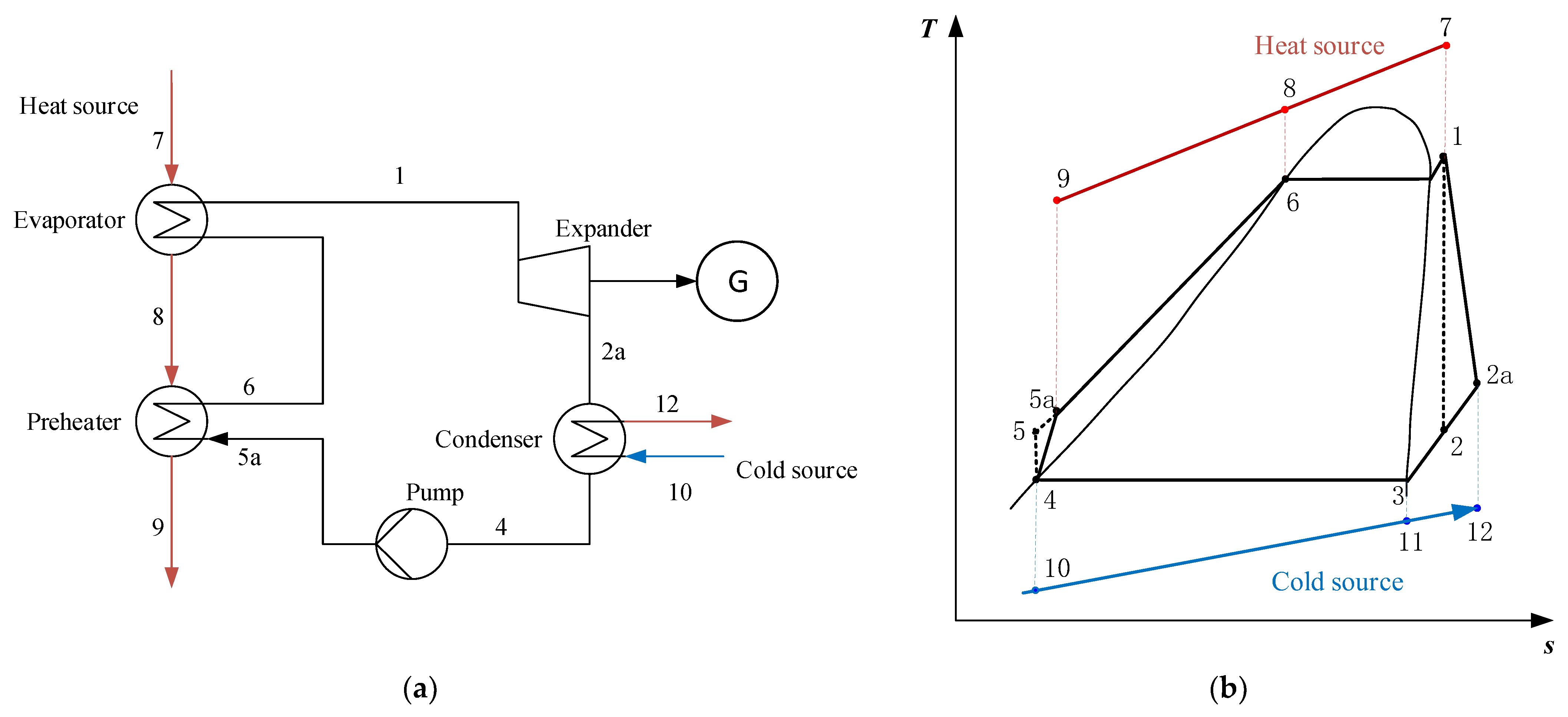
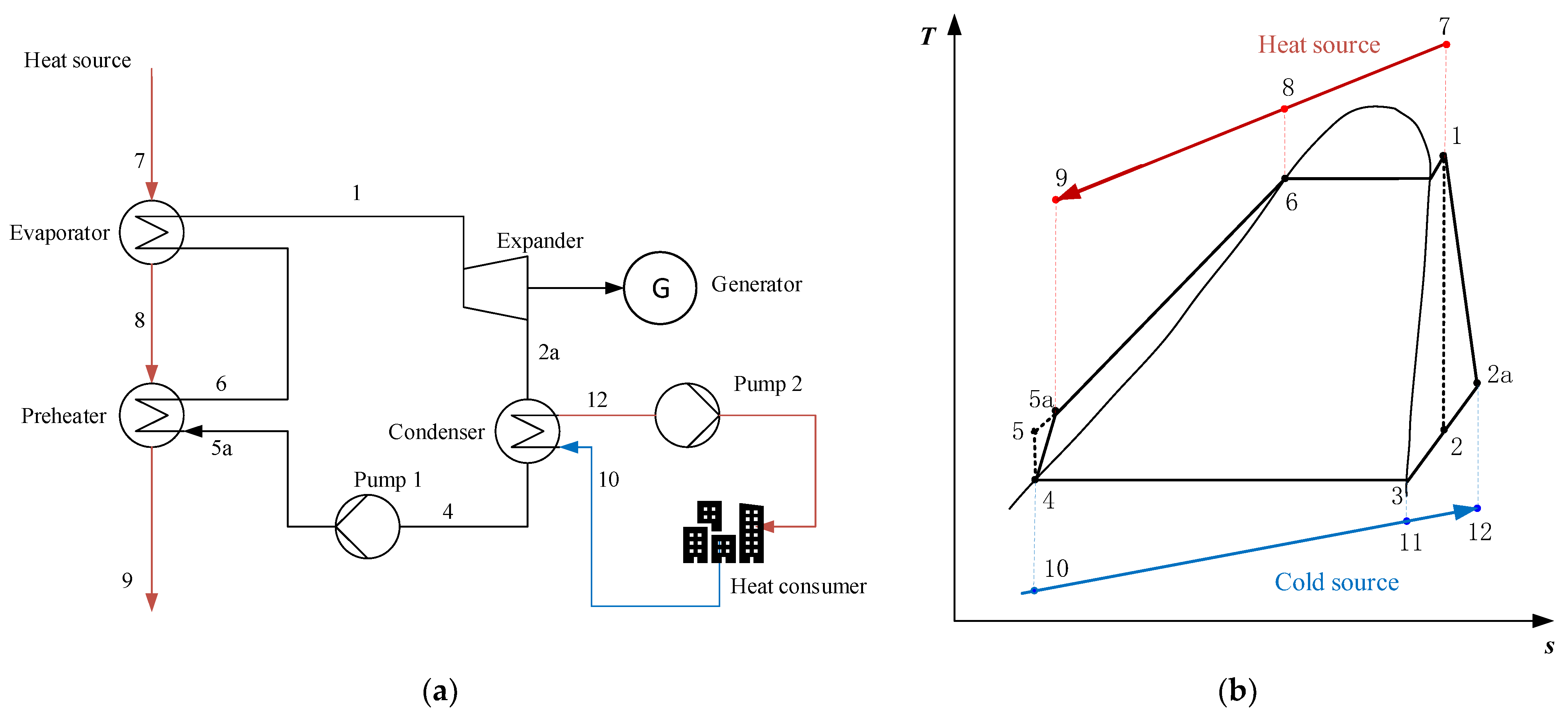
2.1.2. Serial System (SS)

The cycle configuration of the serial ORC-CHP system (SS) and the T-s diagram are shown in Figure 2. It can be seen that after heating the organic working medium, the heat source still has part of the waste heat, which enters the hot water heater (Hwh) to heat domestic hot water (process 9 to 15). At the same time, a cooling tower is applied to reduce the temperature of the cold source. In this study, the heat source comes from the flue gas discharged from industrial production, and water is adopted as a cold source [27].

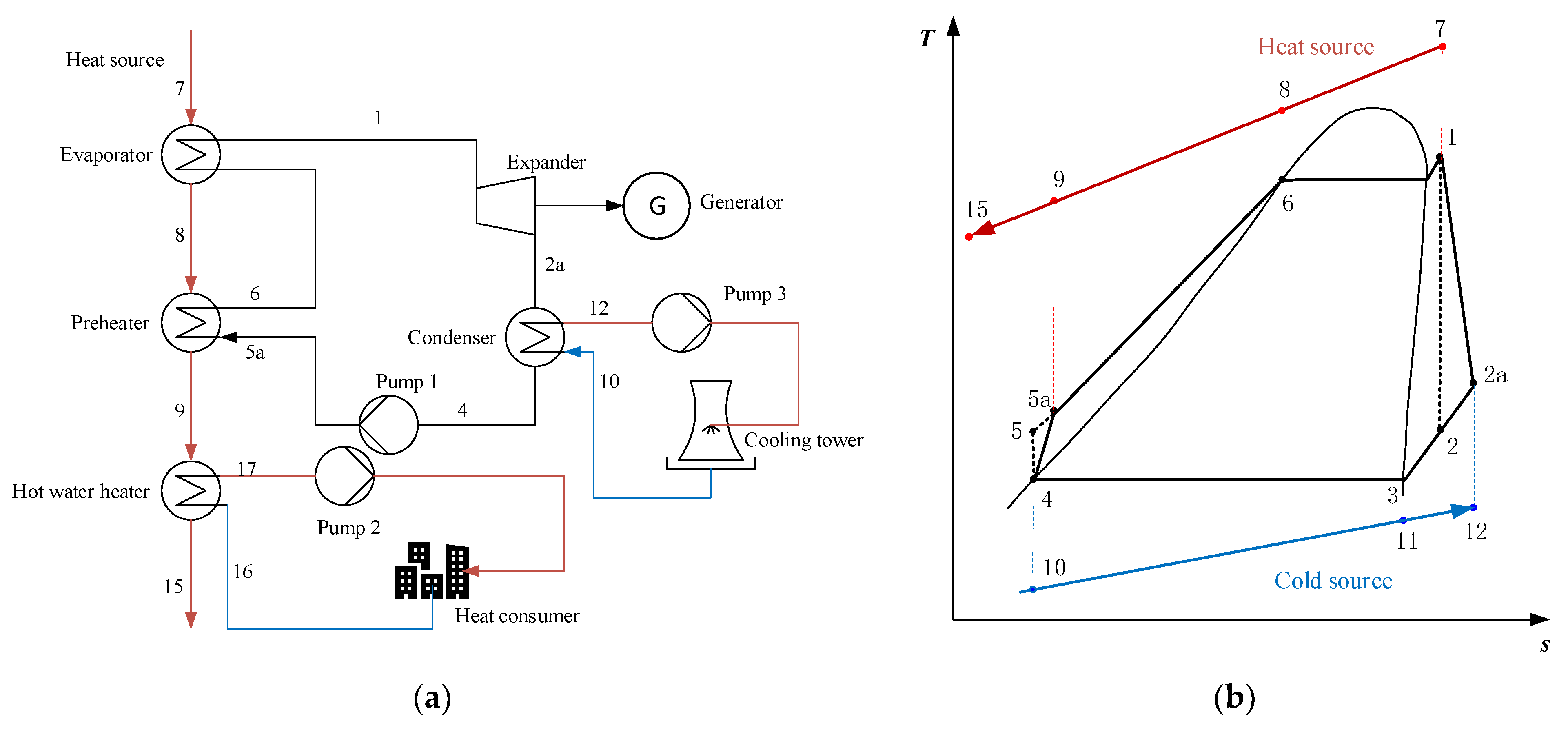
2.1.3. Condensation System (CS)

The cycle configuration of the condensation system (CS) and the corresponding T-s diagram are shown in Figure 3. The condensation system is configured similarly to the basic ORC system, except that the domestic hot water in the condensation system is heated by the heat released by the gaseous organic working substance in the condenser

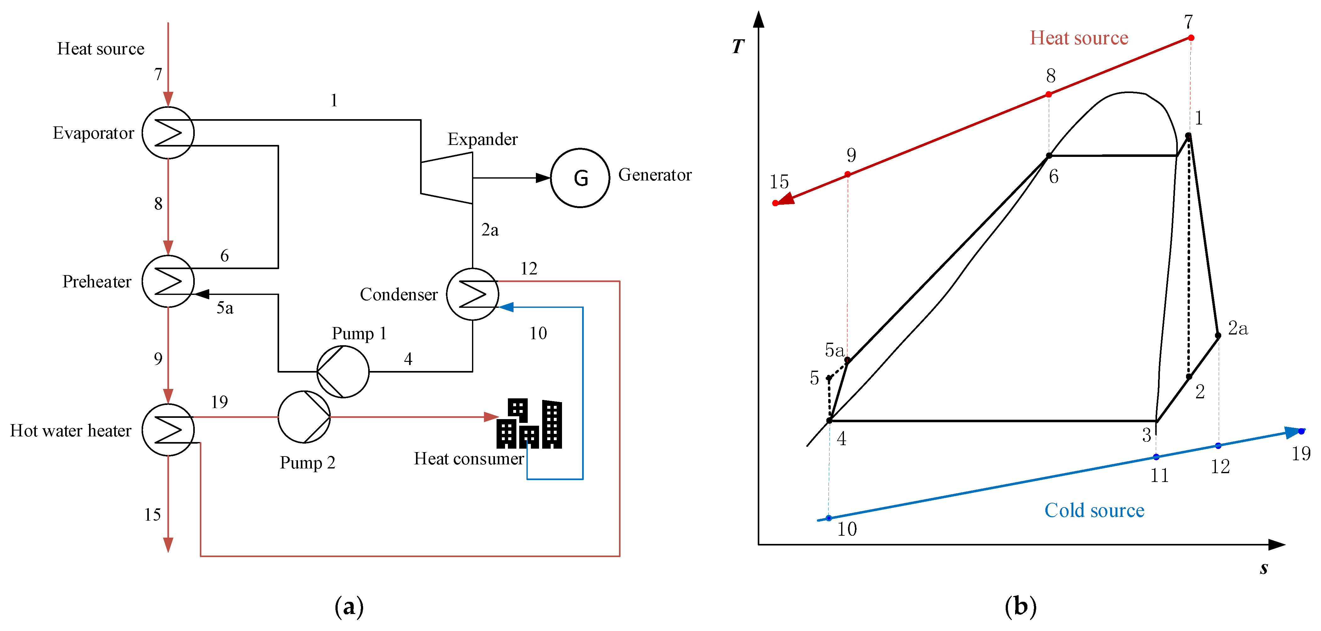
2.1.4. Serial/Condensation System (SS/CS)

The cycle configuration and the corresponding T-s diagram of the serial/condensation system (SS/CS) are shown in Figure 4. Different from the two systems proposed above, the heat supplied to the heat consumer can be divided into two parts: one part is the heat released by the gaseous organic working fluid in the condenser, and the other part comes from the residual heat of the heat source after heating the organic working fluid.

2.2. Mathematical Methods

The proper mathematical model and calculation should be adopted to further accurately study the performance of the proposed systems. At the same time, it is necessary to make reasonable assumptions about some conditions to reduce the complexity of the model. Before the analysis of the system, the following assumptions were adopted in this study: (1) all the systems and components operate under stable conditions, (2) the pressure drops and heat loss of pipes and heat exchangers (evaporator, preheater, water heater, condenser) are ignored, (3) efficiencies of the pump and the turbine remain stable, and (4) the values of the parameters used in the calculation of the model are provided in Table 1.

2.2.1. Selection of Working Fluid

Choosing the right working fluid is one of the necessary conditions for the efficient operation of ORC systems. Different criteria need to be considered when selecting the working fluid, such as thermal efficiency, exergy efficiency, and system economy [30]. In addition, the thermodynamic properties of the organic working fluid need to be reasonably matched with the temperature of the heat source [31]. The critical temperature of the working fluids should not be much lower than the temperature of the heat source, and the reason for this is that if the system operates near the critical point, small perturbations may cause drastic changes in the state of the fluids, which may make the system performance unstable [32]. Furthermore, working fluids that have a negative impact on the environment should not be adopted according to the Montreal Agreement [33] (e.g., R11, R12, R123, R141b, and others).
Based on the above analysis, 12 organic working fluids were pre-selected, and their thermodynamic properties are shown in Table 2. All the data were obtained from NIST REFPROP 9.1.

2.2.2. Exergy Analysis

The subscripts of the formulas below represent the state points in Figure 1, Figure 2 and Figure 3. Exergy analysis was performed in this study to evaluate the thermodynamic performance of the three ORC-CHP systems. Exergy, which is the part of the energy that can theoretically be converted into any other form of energy when the system changes reversibly from any state to a state in equilibrium with the given environment, represents the quality of energy contained in the working substance at each state point [34]. The exergy of the working fluid at each state point, i, can be written as follows:
E i · = m · [ ( h i h 0 ) T 0 ( s i s 0 ) ]
where h is the enthalpy of the fluid and s is the entropy. h0 and s0 represent enthalpy and entropy values at ambient temperature (298.15 K) and pressure (101.3 kPa), respectively.
The key exergy equation for each component can be described as:
E in · = E out · + I · + W ·
where E in · and E out · represent exergy rates of entry and exit from each component, respectively. I · is the exergy destruction of each component. The total exergy destruction of the system is the sum of the exergy loss of all parts. The exergy destruction calculation formulas of the three systems are shown in Table 3.
W · is the power output of the expander. For the pumps, the value of W · is the negative form of the value of the pump power consumption.
Taking the serial system, for example, the power generated by the expander and pump power consumption can be calculated as follows:
W · exp = m · ( h 1 h 2 a ) = m · ( h 1 h 2 ) η exp
W pump 1 · = m · ( h 5 a h 4 ) = m · ( h 5 h 4 ) / η pump
where η exp and η pump are the isentropic efficiency of the expander and pump, respectively.
The net output power of the ORC system, W · net , can be computed as:
W · net = W · exp W · pump
According to the net output power of the system and the exergy destruction of all components, the overall exergy efficiency of the system can be obtained by:
η ex = W · net W · net + I ·
Furthermore, to calculate the net power output of the system, it is necessary to obtain the mass flow rate of the organic working fluid, which can be calculated as:
m · = m h · c ph ( T 7 T 8 ) h 1 h 6
where m h · and c ph are mass flow rate and the specific heat of the hot gas at constant pressure, respectively. T 8 is the temperature of the source at the end of the evaporation process, which can be expressed as:
T 8 = T 6 + T Pinch
where T Pinch is the pinch point, which is the minimum temperature difference of heat exchangers, and T 6 can be determined by the saturation point of the organic working fluid.

2.2.3. Economic Analysis

Since the income of the three proposed systems includes power income and heating income, the profit ratio of investment (PRI) was selected as the economic evaluation index of the system, which can be defined as:
P R I = N A I C tot
where C tot signifies the initial investment cost required for the system. The cost of expanders, heat exchangers, pumps, and other components, such as cooling towers, were all taken into account. The total initial investment cost of the serial system can be calculated as follows:
C tot = ( C ORC + C pump 2 + C pump 3 + C Hwh ) C E P C I 2019 C E P C I 1996 + C ct + C wf
where CEPCI is the chemical engineering plant cost index considering the effect of time on purchased equipment cost, which is widely adopted for updating the capital costs of process engineering projects [35]. CEPCI1996 and CEPCI2019 represent the chemical engineering plant cost index in 1996 and 2019 respectively, and their values are 382 and 652.9, respectively. The cost of the cooling tower, C ct , accounts for 23.48% of the cost of the condenser, and C wf means the cost of the working fluid, accounting for 2% of the total investment [18]. C ORC refers to the total initial investment required for the ORC subsystem, which is described as:
C ORC = C eva + C exp + C con + C pump 1
The calculation formulas of total initial investment costs of CS and SS/CS are shown in Equations (12) and (13), respectively:
C tot = ( C ORC + C pump 2 ) C E P C I 2019 C E P C I 1996 + C wf
C tot = ( C ORC + C pump 2 + C Hwh ) C E P C I 2019 C E P C I 1996 + C wf
NAI means the annual net profit of the ORC-CHP system, which is expressed as:
N A I = E N E + E N H C man
where E N E and E N H represent the annual income of the system from generating electrical power and supplying heat, respectively. The two kinds of income can be calculated as follows:
E N E = W · net t op P e
E N H = m · dhw t op P dhw
where m · dhw is the mass flow rate of domestic hot water to be heated, and can be calculated according to the law of conservation of energy. For example, in the serial system, the mass flow rate of domestic hot water is defined as:
m · dhw = m h · c ph ( T 9 T 15 ) c pc ( T 17 T 16 )
where c pc is the specific heat of the hot water at constant pressure, t op is the operation time of the system, which is assumed as 7500 h, and P e and P dhw are the sales prices of electric power and domestic hot water respectively, which are supposed as 0.13   $ / kWh and 3.6   $ / t in this study [18].
C man is the cost of ensuring the stable operation and maintenance of the system, and it can be calculated as:
C man = γ M C tot
where γ M is the ratio of maintenance costs for the total system investment, which is assumed as 1.5%.
The module costing technique (MCT) is usually used to calculate the cost of specific components, so as to analyze the economic performance of the systems [36]. The cost of purchasing a component can usually be assessed as follows:
log C P , X = K 1 , X + K 2 , X log Y + K 3 , X ( log Y ) 2
where X represents the different components shown in Table 4, and Y means the area of the heat exchanger or the capacity of the expander and pump, respectively.
C P is the basic cost of each component, which is obtained when the component runs under rated pressure. However, these components often do not work under rated pressure, which means that pressure correction of the above formulas should be carried out. The corrected cost of pumps and heat exchangers can be expressed as:
C BM = C p ( B 1 + B 2 F M F P )
where C BM is the corrected cost, and F M is the material correction factor. F P is the pressure correction factor, which is defined as:
log F P = C 1 + C 2 log P + C 3 ( log P ) 2
where P is the working pressure of each component.
For the expander, the corrected cost is calculated as:
C BM = C P F bm
The correction coefficients mentioned in Equations (19)–(22) can be found in the reference [11].

2.3. Optimization Method

All codes in this study were written in MATLAB R2018a and the thermal properties of the organic working fluids used were obtained by NIST REFPROP 9.1 [37].

2.3.1. Multi-Objectives Optimization

Many optimization problems in engineering practice are multi-objective optimization design problems. In general, multiple objectives are in a state of conflict, and there is no optimal design to make all objectives achieve the optimal states at the same time. The improvement of the performance of one target often comes at the cost of the reduction of the performance of one or more other targets [38]. The multi-objective optimization problem can be described as follows:
{ Maximum : F ( x ¯ ) = [ f 1 ( x ¯ ) , f 2 ( x ¯ ) , , f k ( x ¯ ) ] T x ¯ X X R m
where x ¯ is the variable space to be optimized, k is the number of target functions, and X represents the set of all the solutions that satisfy the constraint.
The Pareto optimal solution of the multi-objective optimization problem is a set of acceptable “not bad” solution sets. The solution is Pareto optimal if no other solution exists to make each objective function better. Compared with single-objective optimization, the final result converges to a specific point, and the result of multi-objective optimization exists in the form of a set of solution sets.

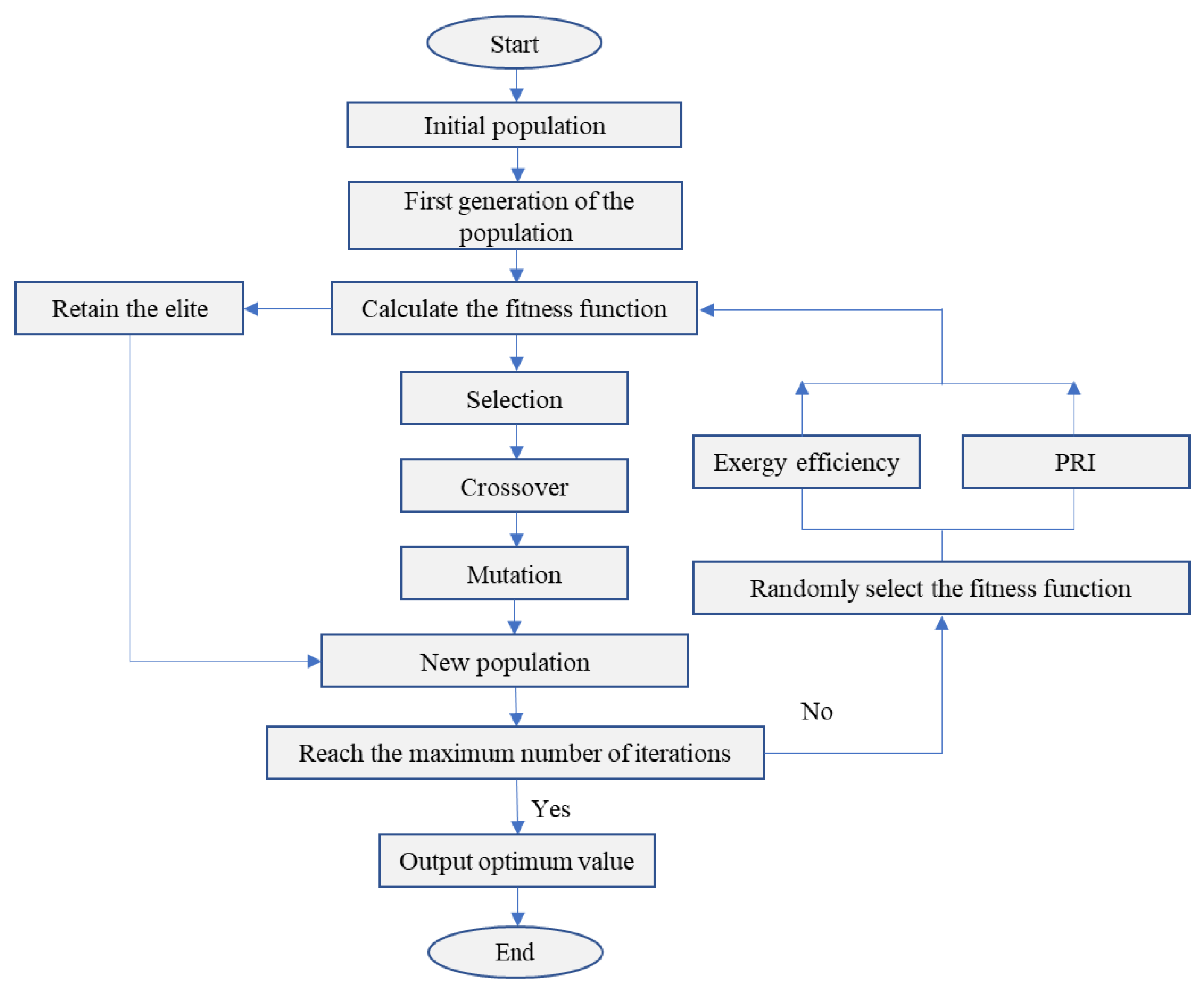
2.3.2. Multi-Objective Genetic Algorithm

The multi-objective genetic algorithm has been widely used in engineering optimization technology [39]. The genetic algorithm (GA) is inspired by natural biology and speeds up convergence through selection, crossover, mutation, and other operations. It is a kind of search algorithm, through continuous search and trial and error, and when the result meets the accuracy requirement or iterates to the maximum algebra, the program will be terminated.
In this work, the temperature and pressure at the expander inlet (i.e., T 1 and P 1 ) are selected as two parameters to be optimized. A two-dimensional array [ T 1 , P 1 ] is generated as a chromosome for each individual. Constraint conditions required to generate T 1 and P 1 are as follows:
T 1 max = min { ( T crit 10 ) , ( T gas 8 ) } ; P 1 max = P sat , T 1
where ( T crit 10 ) is set to prevent instability caused by the organic working fluid operating near the critical point [40]. At the same time, the maximum temperature, T 1 , cannot be greater than ( T gas 8 ) due to the limitation of the temperature difference between pinch points. P sat , T 1 is determined by T 1 to ensure that the organic working medium is saturated or overheated when entering the expander. The lower limits of T 1 and P 1 are also set so that the outlet temperature of the heat source (state point 15 in Figure 2 and Figure 4, and state point 9 in Figure 3) is 15 K higher than the acid dew temperature.
The exergy efficiency, η ex , and profit ratio of investment, PRI, are selected as the target functions in this work, which can be expressed as:
( η ex , P R I ) = f ( T 1 , P 1 )
As an important step in the genetic algorithm, the “selection” process embodies the rule of survival of the fittest. The individuals with higher fitness are selected from all the individuals to produce the next-generation population. As in natural processes, “crossover” involves the swapping of genes on the chromosome of the selected parent. The process of “mutation” causes some genes on a single chromosome to change to avoid obtaining the local optimal solution. Last but not least, the elite retention strategy is adopted to protect the genes of high-performing individuals from being damaged. The complete implementation process of the genetic algorithm is shown in Figure 5. Table 4 shows the values of each parameter of the GA in this work.

3. Results and Discussion

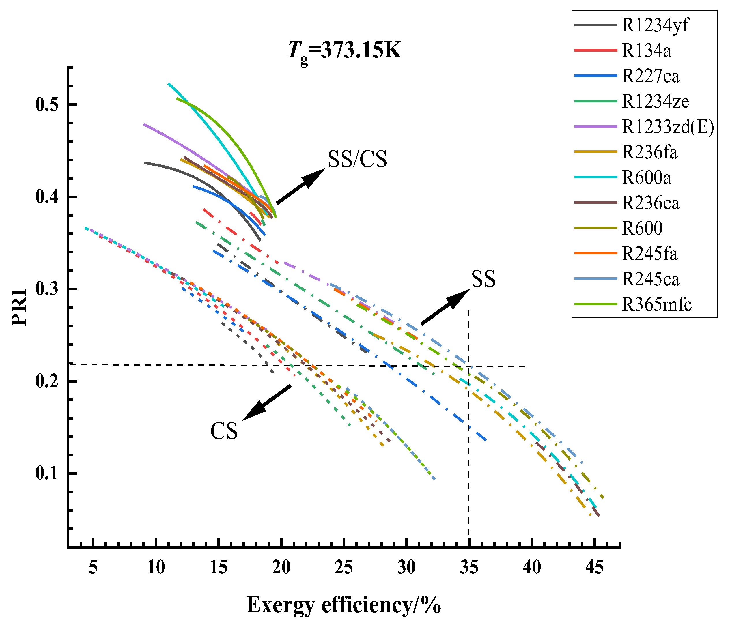
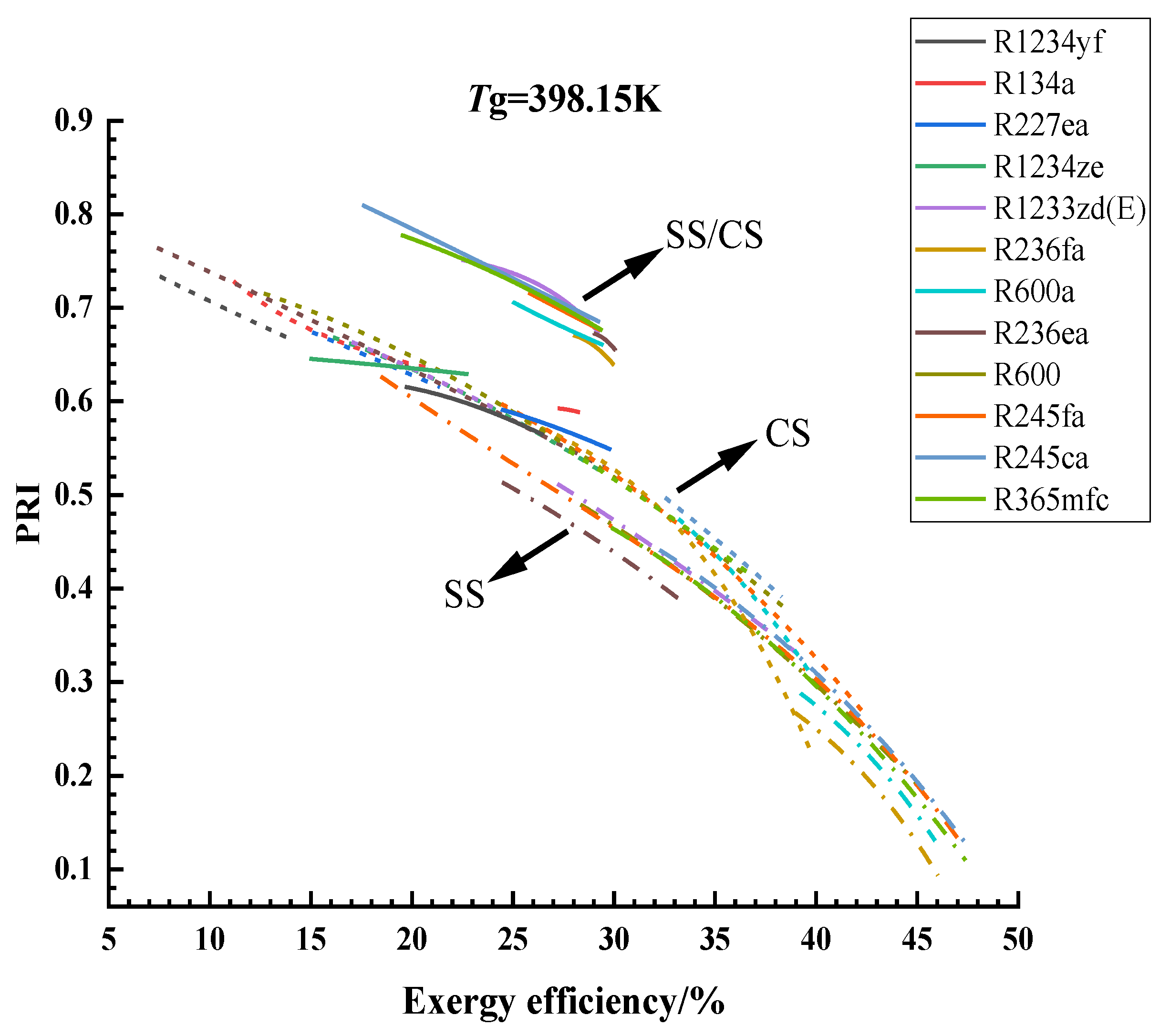
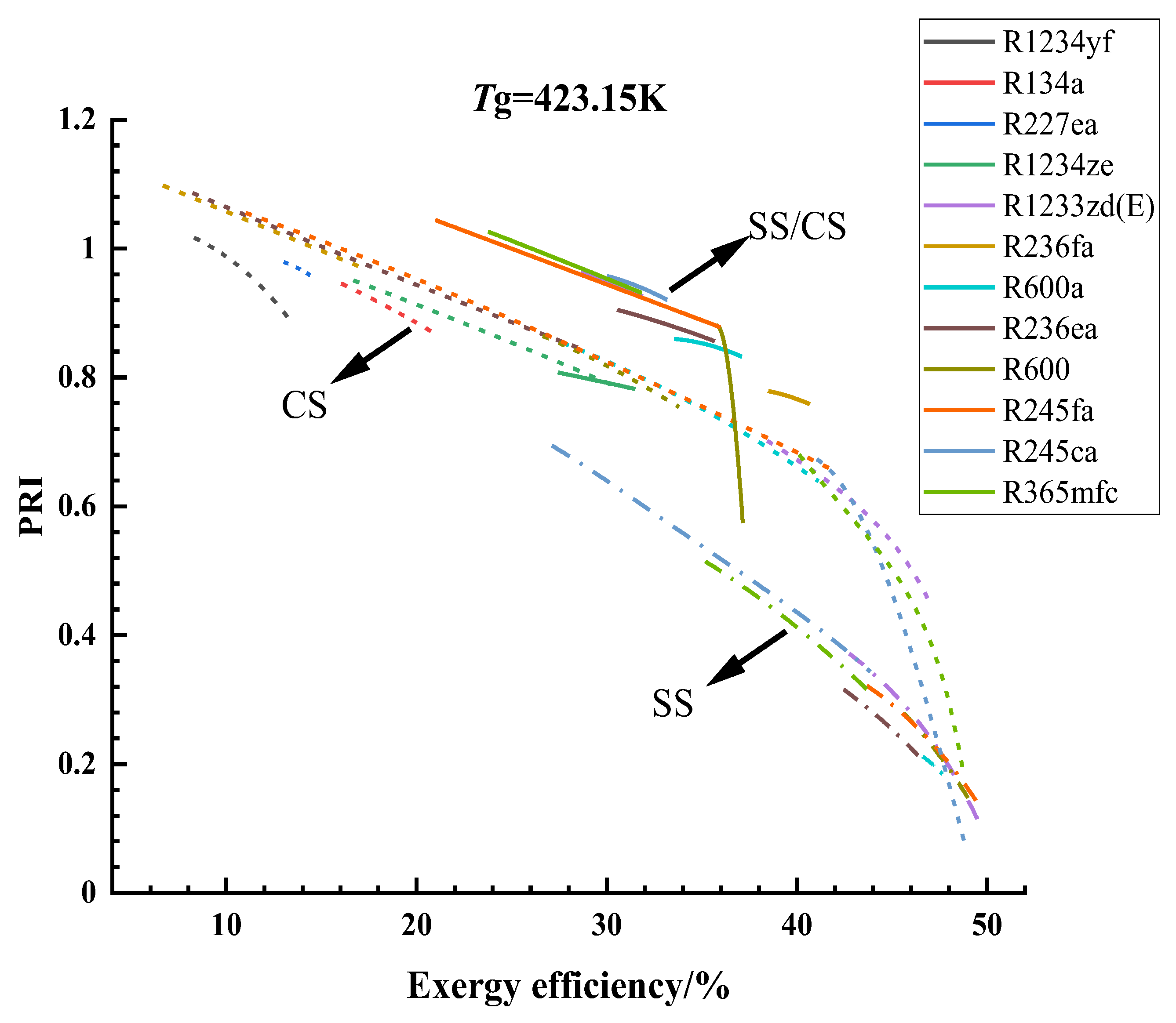
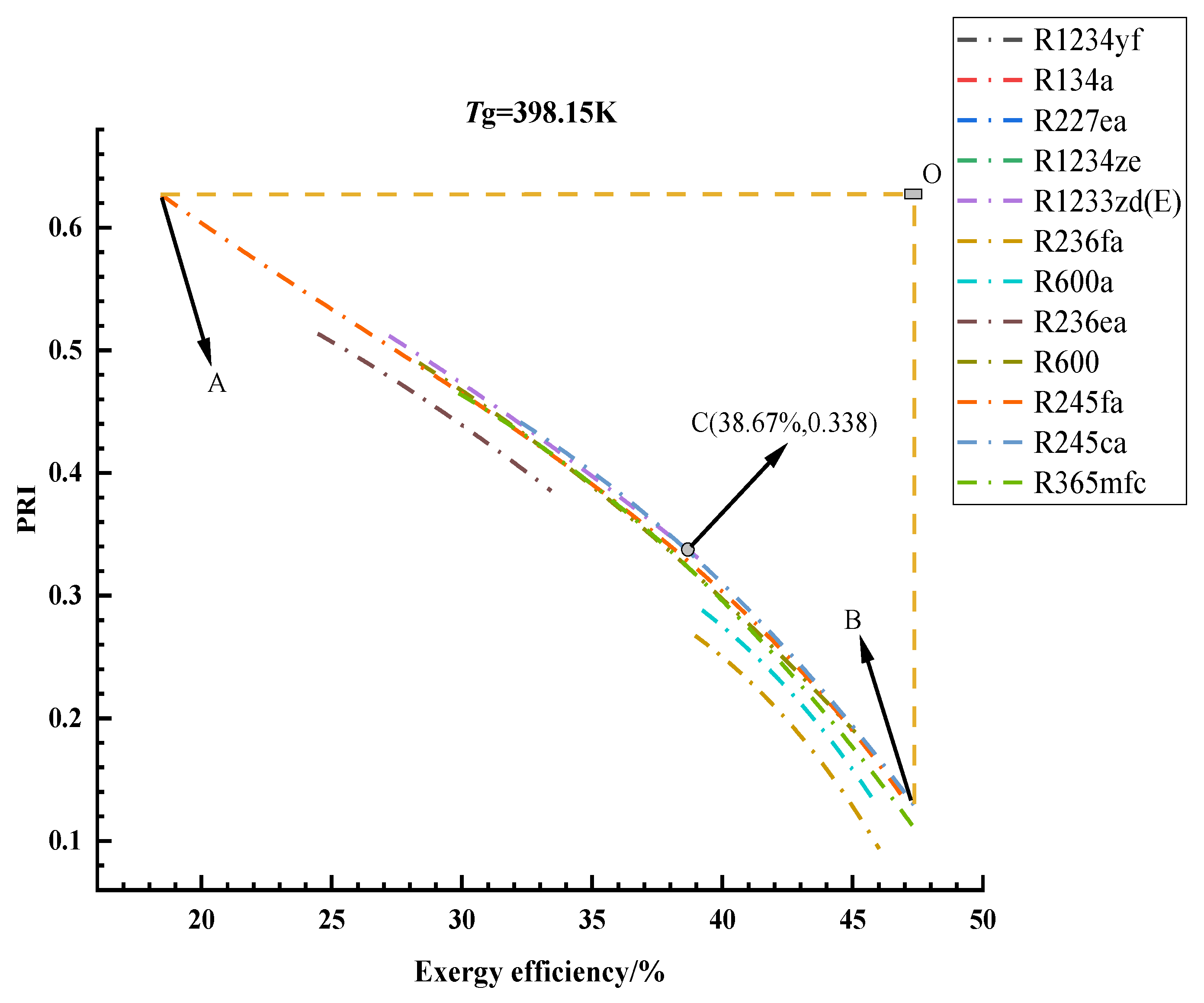
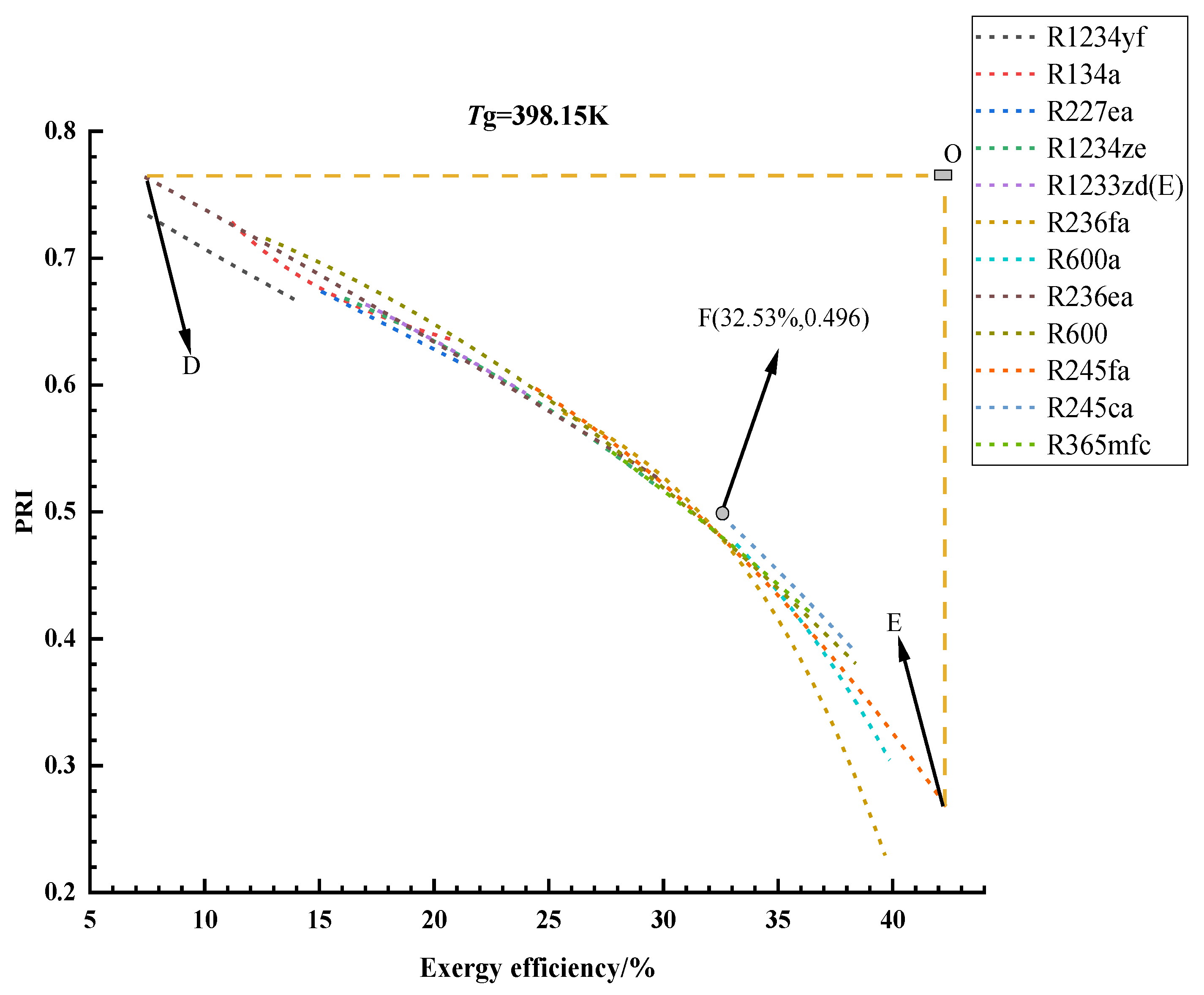
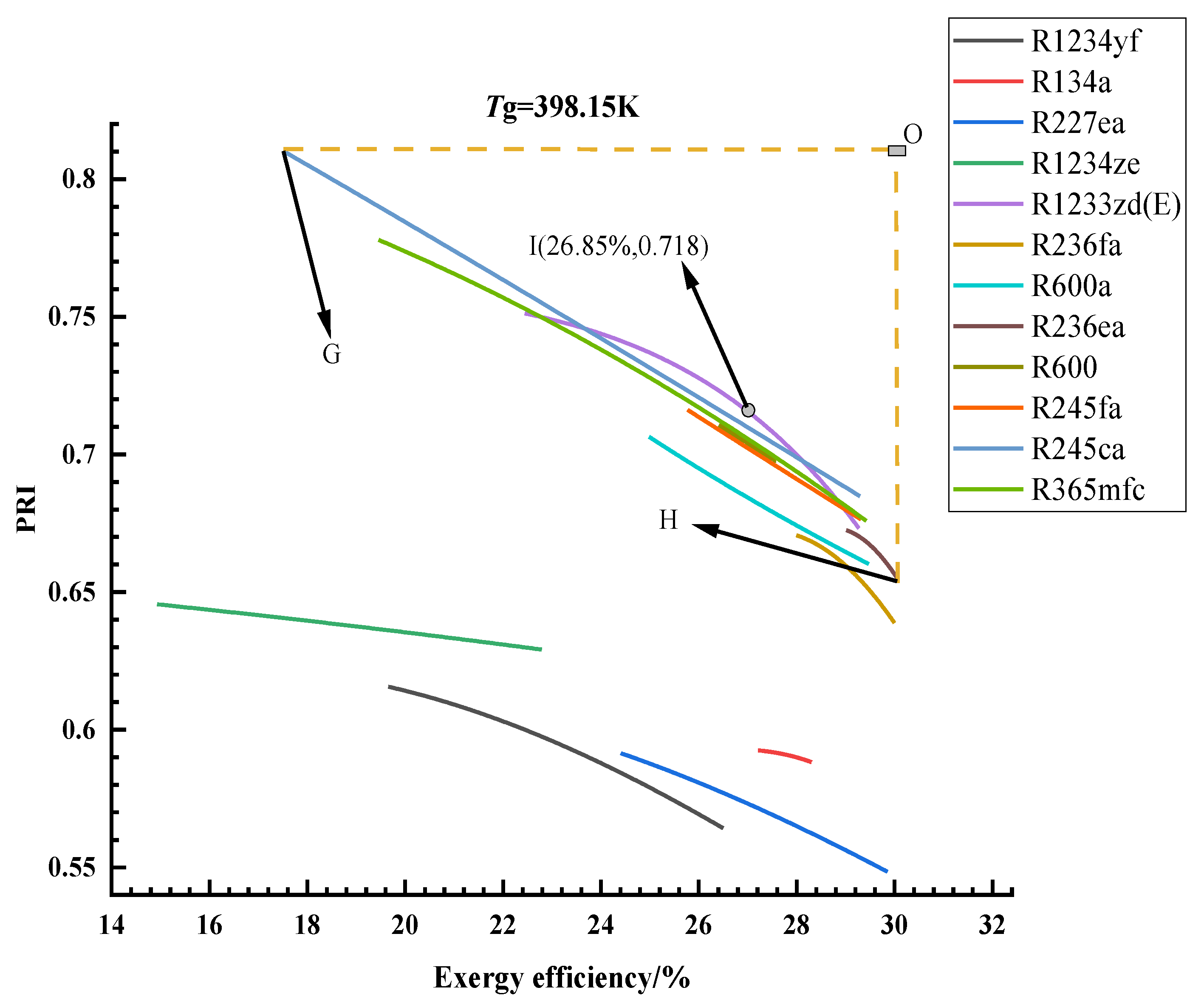
3.1. Optimization Results and Analysis

The optimization results of different organic working fluids adopted in the three ORC-CHP systems under different heat source temperatures are shown in Figure 6, Figure 7 and Figure 8, respectively. Different lines are used to distinguish between SS (dotted line), CS (short line), and SS/CS (solid line). At the same time, the different colored lines in the legend represent different organic working fluids, and this is true for the three figures. T g refers to the initial temperature of the heat source gas, which is 373.15, 398.15, and 423.15 K, respectively.
As can be seen from the optimization results, the Pareto optimal solution exists in the form of a group of numbers, and the improvement of exergy efficiency is bound to lead to the decline of the economic performance of the system, and vice versa. Meanwhile, the economic benefits and thermal performance of different systems and organic working substances are distributed in different ranges, which are determined by the form of the systems and the thermodynamic properties of the organic working fluids. For example, when the temperature of the heat source is 373.15 K, it can be seen from Figure 6 that the overall exergy efficiency of SS is higher than that of CS, while the PRI value of the two systems is almost within the same range. On the other hand, the economic performance of SS/CS is unimpeachable at this time, but its exergy efficiency is generally low. Therefore, we can judge that when the heat source temperature is relatively low, SS is the best choice, SS/CS is the second, and CS should not be recommended under this condition. Then, when the temperature reaches 398.15 K, it can be seen from Figure 7 that SS and CS are neck and neck in the evaluation of the two performance indexes, and even the economic performance of CS is slightly higher than that of SS. Therefore, through the analysis of the above case, it is essential to choose the appropriate ORC-CHP system and organic working fluid according to the actual engineering requirements.
The selection of system form and organic working fluid should be carried out according to specific conditions and requirements. The following examples illustrate how to select the corresponding system and working medium according to the given conditions and requirements: Assuming the temperature of the heat source is 373.15 K and the exergy efficiency of the system is required to be above 35%, it can be seen from Figure 6 that only SS can meet the above conditions, and R245ca can be considered as the best organic working fluid. The maximum profit ratio of investment the system can achieve at this point is 0.219. In the same way, the best system configurations and organic working fluids can be selected to meet the specific requirements, within the range of effects that can be achieved.
Furthermore, it can be seen from Figure 6, Figure 7 and Figure 8 that there are some curves with very low slope, such as the optimization results of SS/CS using R1234ze when the heat source temperature is 398.15 K. In this case, when the system has higher exergy efficiency, the cost of reduced economic performance is within the acceptable range. Therefore, the system should be operated under the condition of high exergy efficiency as far as possible. On the contrary, for those curves with high slope, the sharp decline in economic performance caused by higher exergy efficiency is worth considering.
Taking the heat source temperature of 398.15 K as an example [41,42], the performance of the three systems under optimal working conditions should be analyzed in detail. To facilitate the further analysis of the optimal working conditions of each system, it is necessary to find an optimal solution of each system when the heat source temperature is 398.15 K. The optimization results of SS are more clearly shown in Figure 9. When the economic performance of the CHP system is the primary goal, point A is the optimal solution of the system, but at this time, the exergy efficiency is also the lowest. On the contrary, when the exergy efficiency of the system is regarded as the greatest goal, there is no doubt that point B will be the best solution for the system, but the economic performance of point B is not very ideal, which cannot be ignored. Therefore, in this study, point O is used to find the best solution of the system [19]. It can be seen that point O is the point with the best economic performance and the highest exergy efficiency. However, since the performance of point O is beyond the reach of the actual system operation, point C, that is, the point closest to point O in the curve, is taken as the optimal solution of the system. At the same time, since point C falls on the curve representing R245ca, R245ca can be considered as the most competitive working medium applied to SS when the heat source temperature is 398.15 K. Similarly, the optimal solutions of CS (F) and SS/CS (I) are shown in Figure 10 and Figure 11, respectively. It can be seen that when the heat source temperature is 398.15 K, the optimal working medium of SS is R245ca and R1233zd(E) (38.67%, 0.338), and that of CS is R245ca (32.53%, 0.496). For SS/CS, it is obvious that R1233zd(E) (26.85%, 0.718) will be the optimal choice.
The above method can be used to analyze the working conditions with the heat source temperatures of 373.15 and 423.15 K, and the results show that when the heat source temperature is 373.15 K, the optimal working mediums corresponding to SS, CS, and SS/CS are, respectively: R245ca (38.99%, 0.178), R245fa (20.38%, 0.242), and R365mfc (15.80%, 0.468). When the heat source temperature reaches 423.15 K, the optimal working mediums corresponding to the three systems are R1233zd(E) (42.68%, 0.378), R245ca (41.22%, 0.671), and R245fa (35.81%, 0.881), respectively. Therefore, it is feasible to select the system under different heat sources according to the above optimum conditions and combined with the actual engineering requirements. Under the condition of a heat source temperature of 373.15 K, SS has the highest exergy efficiency, while SS/CS has the best economic performance, which is similar to the results when the heat source temperature is 398.15 K. When the temperature of the heat source reaches 423.15 K, compared with the highest exergy efficiency of SS and the best economic performance of SS/CS, CS will be the optimal solution considering these two objective functions.
According to the above calculation of optimal working conditions, it can be learned that R245ca and R1233zd(E) are the working mediums that can satisfy the most system and working conditions, followed by R245fa. R245fa has been considered the optimal working medium in some studies that have been carried out [43,44,45]. At the same time, it has also been mentioned in some studies that R245ca is the optimal working medium for ORC systems [46,47]. Therefore, for ORC-CHP systems, the optimal working medium is not the same, which is mainly determined by the system form and the research or optimization objectives. It is worth noting that the high GWP (Global Warming Potential) values of R245fa and R245ca will increase the potential risks for climate change mitigation. However, as a transitional working medium, R245ca’s excellent performance in this study is still of important reference significance. Meanwhile, it is necessary to study some environmental protection working fluids such as R1233zd(E) from the perspective of the environment [48].

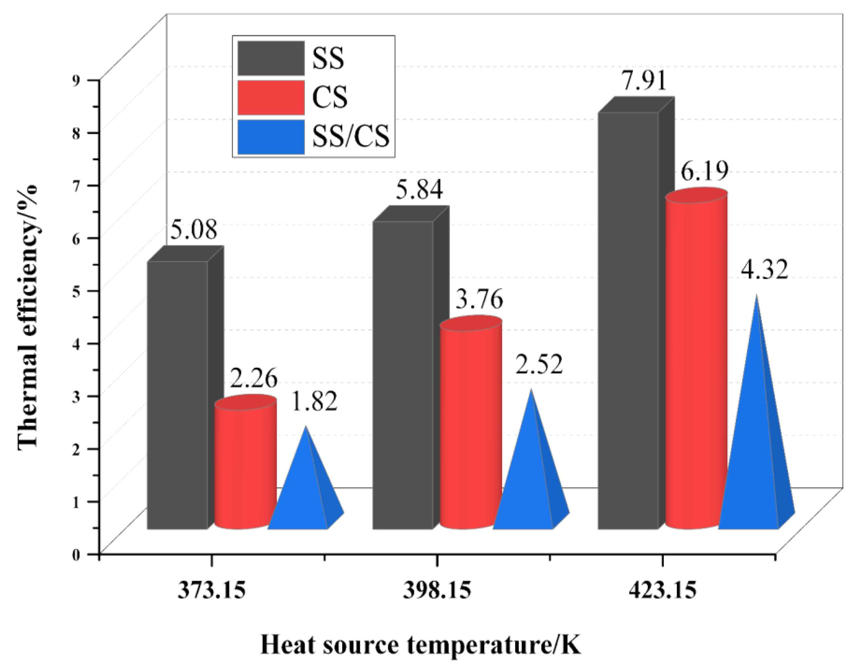
3.2. Thermodynamic Cycle Efficiencies of the Optimal Solutions

The thermal efficiency of the systems can be defined as:
η th = W · net Q ·
where Q ˙ presents the total heat that the working medium obtains from the heat source. For CS, it is given by:
Q · = m · ( h 1 h 5 a )
For SS and SS/CS, the total heat absorbed by the two systems from the heat source can be expressed as:
Q · = m · ( h 1 h 5 a ) + m h · ( h 9 h 15 )
Therefore, according to the above formulas and the optimal working conditions obtained, the thermal efficiency of each system can be obtained under the optimal operating conditions. Under different heat source temperatures, with the optimal combination of exergy efficiency and PRI value, the thermal efficiency of each system is shown in Figure 12. It can be seen that SS always has higher thermal efficiency than the other two systems when all three systems operate under the optimal conditions. The main reason for this is that the SS has more net power output under the best operating conditions. At the same time, it can also be seen that the thermal efficiency of the three systems increases with the increase of the temperature of the heat source. In other words, higher reservoir temperatures lead to higher energy efficiency. However, it should be noted that such results are only found in this study; that is, within the temperature range of the heat source selected in this study, the thermal efficiency of the three systems proposed in the optimal operating conditions will increase with the temperature of the heat source.

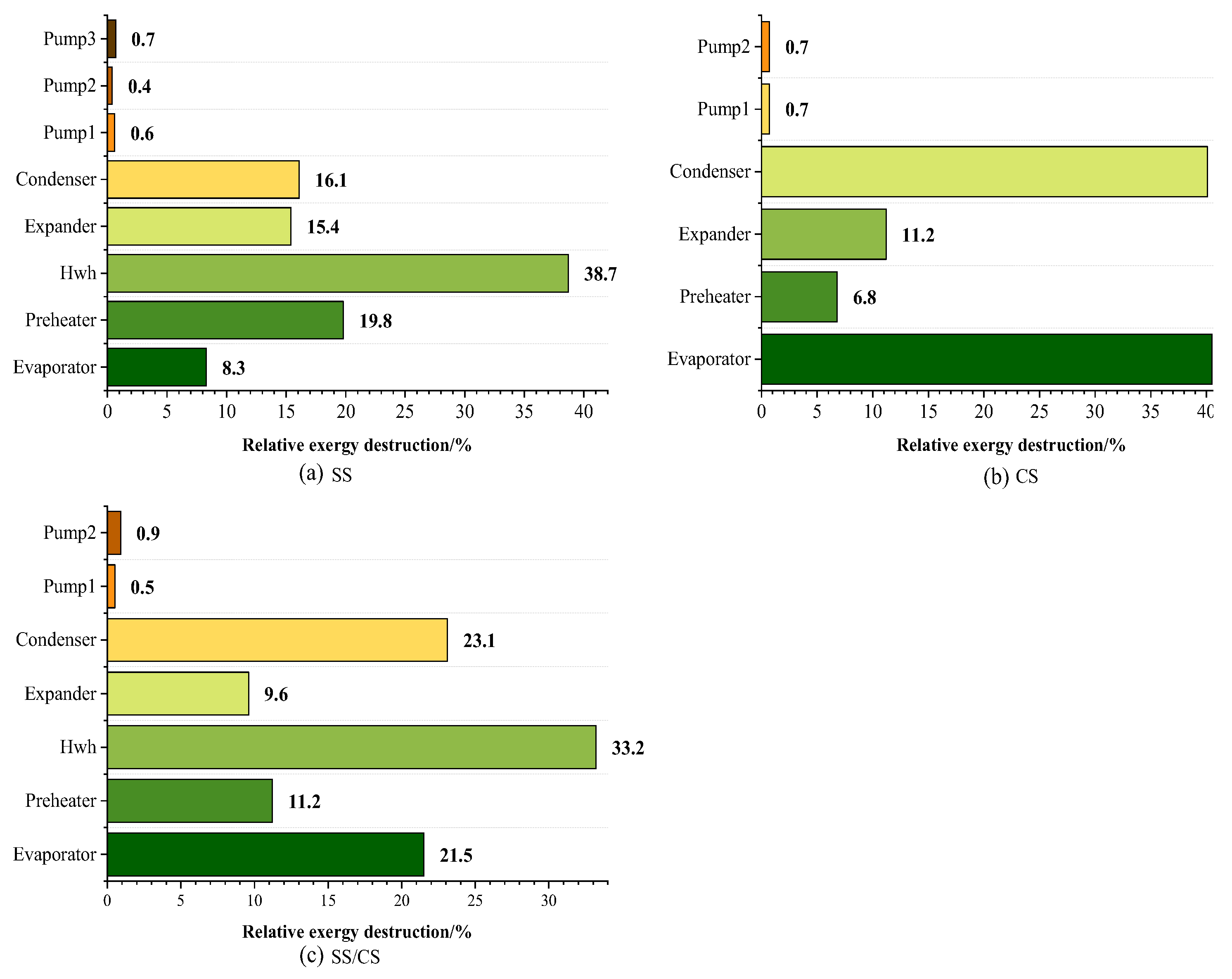
3.3. Exergy Analysis of the Optimal Solutions

The optimal conditions of the three ORC-CHP systems have been obtained when the heat source temperature is 398.15 K. Exergy analysis on the three optimal working conditions is necessary to carry out. The contribution of each component of the three ORC-CHP systems to the rate of overall exergy destruction at the optimal operating conditions is shown in Figure 13. It can be seen that in the SS (Figure 13a), the exergy destruction in the water heater (Hwh) (38.7%) accounted for the largest proportion of the total exergy destruction of the system, while for CS (Figure 13b), the exergy destruction was mostly caused by the evaporator (40.5%) and condenser (40.1%) under the optimal working condition. In addition, when SS/CS (Figure 13c) was adopted, the components with the largest proportion of exergy destruction were the three heat exchangers, namely: water heater (33.2%), condenser (23.1%), and evaporator (21.5%). From the above exergy analysis, it can be concluded that in the three ORC-CHP systems, the heat exchangers are always the components with the highest contribution rate to the overall exergy destruction. Furthermore, exergy loss caused by the pumps accounted for the smallest proportion of exergy loss in all three systems.

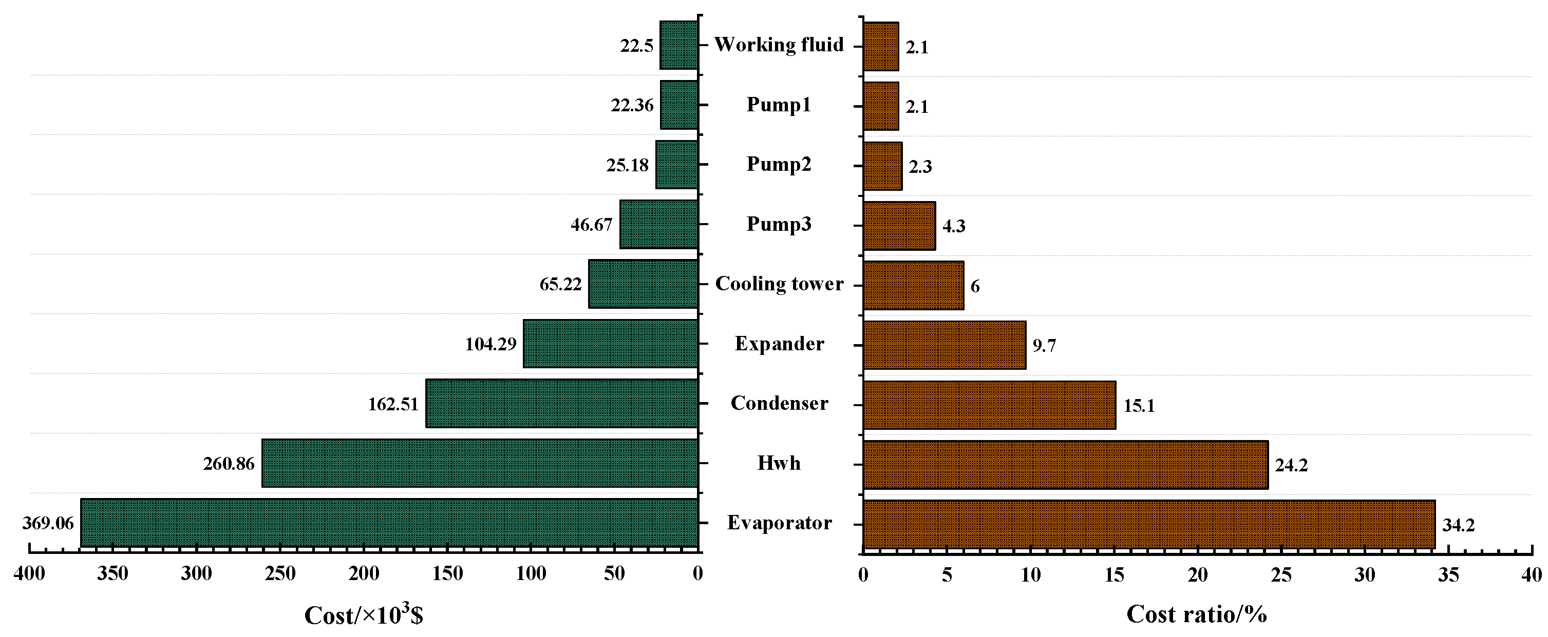
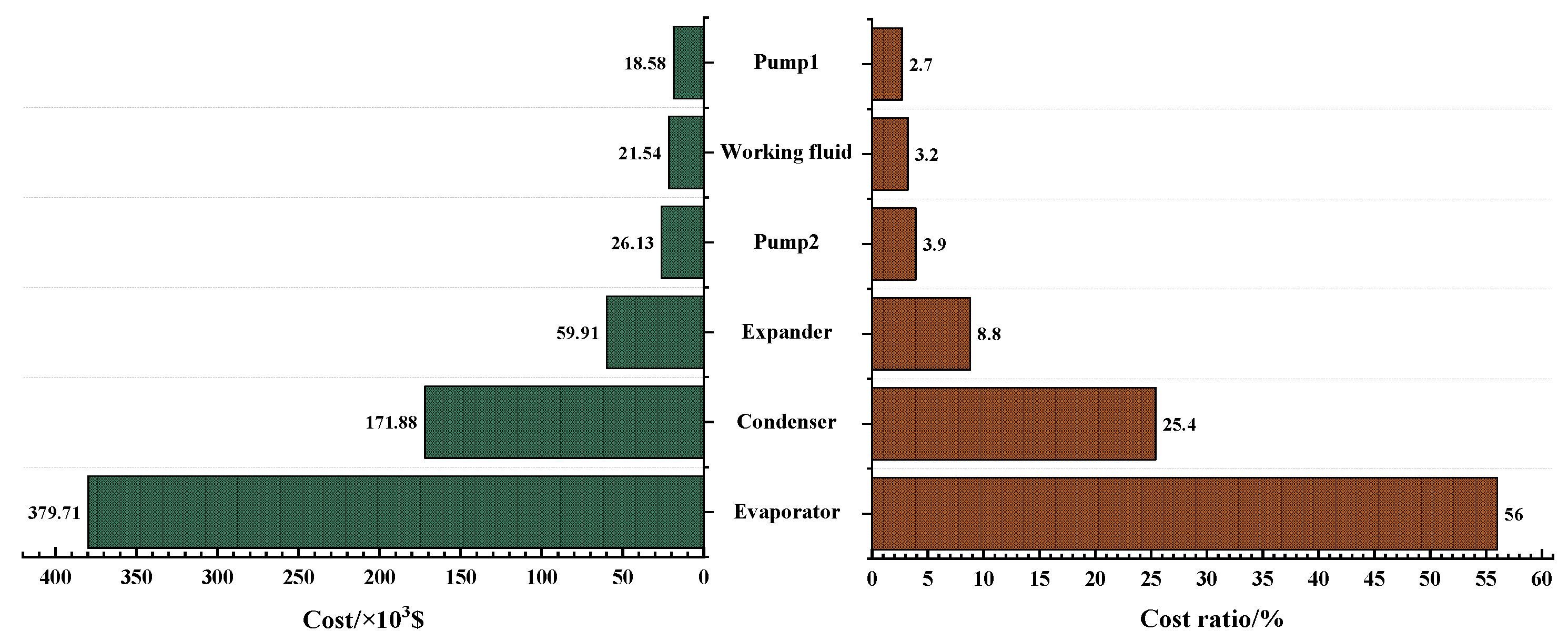
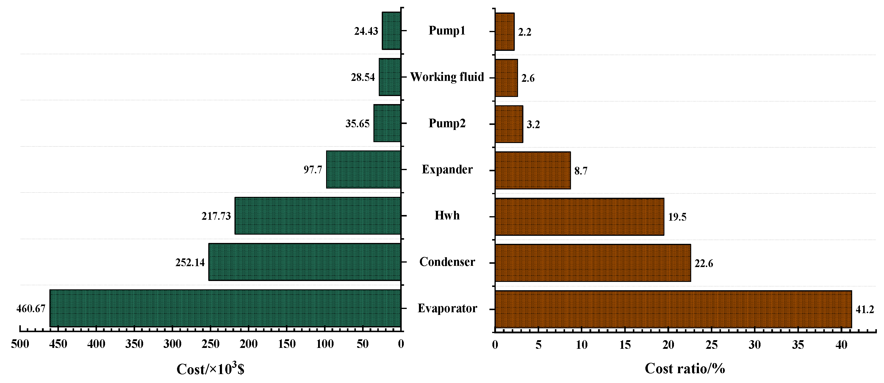
3.4. Economic Analysis of the Optimal Solutions

According to Equations (10)–(22), the economic performance of the three systems under optimal working conditions was evaluated. The component costs of the three systems under the optimal operating conditions described above are shown in Figure 14, Figure 15 and Figure 16, respectively. It can be seen that the components with the highest cost are heat exchangers, which is similar to the result of the exergy analysis above. For example, the three components with the highest equipment cost in SS are the evaporator (34.2%), water heater (24.2%), and condenser (15.1%), followed by the expander (9.7%). Therefore, if the cost of the system needs to be further optimized in the future, the heat exchanger is undoubtedly the key point of optimization.
The electricity and hot water revenues of the three systems under optimal conditions are shown in Figure 17. It can be found that when the three systems are operating in a state of excellent thermal and economic performance, the supply of hot water is the major approach for the systems to obtain revenues. It is important to note that this does not apply in every case, as the results are mainly determined by the local price of hot water and electricity.

4. Conclusions and Future Work

In the present study, firstly, the thermodynamic and economic models of the three systems (SS, CS, and SS/CS) were established. Then, under the conditions that the heat source temperatures are 373.15, 398.15, and 423.15 K, the multi-objective genetic algorithm was used to optimize the three systems respectively, to obtain higher exergy efficiency and PRI. Twelve organic fluids were adopted to evaluate their performance as working fluids in ORC-CHP systems. Finally, the optimal working conditions and corresponding thermal efficiency of the three systems were obtained, and exergy analysis and economic analysis were carried out for the three systems under these optimal working conditions. The main conclusions of the study are summarized as follows:
(1) When the heat source temperature was 373.15 K, the optimal working mediums corresponding to SS, CS, and SS/CS were, respectively: R245ca (38.99%, 0.178), R245fa (20.38%, 0.242), and R365mfc (15.80%, 0.468). Under the heat source temperature of 398.15 K, the optimal working mediums of SS were R245ca and R1233zd(E) (38.67%, 0.338), and that of CS was R245ca (32.53%, 0.496). For SS/CS, R1233zd(E) (26.85%, 0.718) will be the optimal choice. When the heat source temperature reached 423.15 K, the optimal working mediums corresponding to the three systems were R245ca (42.68%, 0.378), R245ca (41.22%, 0.671), and R245fa (35.81%, 0.881), respectively.
(2) Under the condition of a heat source temperature of 373.15 K, SS had the highest exergy efficiency, while SS/CS had the best economic performance, which are similar to the results when the heat source temperature was 398.15 K. When the temperature of the heat source reaches 423.15 K, compared with the highest exergy efficiency of SS and the best economic performance of SS/CS, CS will be the optimal solution considering these two objective functions.
(3) SS always had higher thermal efficiency than the other two systems when all three systems operate under the optimal conditions. The main reason for this is that the SS has more net power output under the best operating conditions. At the same time, the thermal efficiency of the three systems increases with the increase of the temperature of the heat source.
(4) The exergy analysis result under the three optimal working conditions showed that in the SS, the exergy destruction in the water heater (Hwh) (38.7%) accounted for the largest proportion of the total exergy destruction of the system, while for CS, the exergy destruction was mostly caused by the evaporator (40.5%) and condenser (40.1%) under the optimal working condition. In addition, when SS/CS was adopted, the components with the largest proportion of exergy destruction were the three heat exchangers, namely: water heater (33.2%), condenser (23.1%), and evaporator (21.5%).
(5) The components with the highest cost are heat exchangers, which is similar to the result of exergy analysis.
(6) When the three systems are operating in a state of excellent thermal and economic performance, the supply of hot water is the major approach for the systems to obtain revenues.
The results of this study can provide references for ORC-CHP system selection and organic working fluid selection under specific conditions. To cover a wider range of working conditions, it is necessary to conduct further studies on higher temperature conditions and more system forms.

Author Contributions

Conceptualization, S.T. and H.X.; methodology, S.T., Y.-Q.F. and H.X.; software, S.T.; validation, Y.-Q.F., T.-C.H. and H.X.; formal analysis, T.-C.H. and H.X.; investigation, S.T. and H.X.; resources, H.X.; data curation, S.T.; writing—original draft preparation, S.T.; writing—review and editing, Y.-Q.F., T.-C.H. and H.X.; visualization, S.T. and H.X.; supervision, H.X.; project administration, H.X.; funding acquisition, H.X. All authors have read and agreed to the published version of the manuscript.

Funding

This research was supported by the National Natural Science Foundation of China (Nos. 52076163, 51706176), the Key Research and Development Program of Shaanxi (No. 2020SF-404), and the National Postdoctoral Program for Innovative Talents (No. BX20200265).

Institutional Review Board Statement

Not applicable.

Informed Consent Statement

Not applicable.

Data Availability Statement

Not applicable.

Acknowledgments

This work was supported by the National Natural Science Foundation of China (Nos. 52076163, 51706176), the Key Research and Development Program of Shaanxi (No. 2020SF-404), and the National Postdoctoral Program for Innovative Talents (No. BX20200265). The support is gratefully acknowledged.

Conflicts of Interest

The authors declare no conflict of interest.

References

  1. Henry, A.; Prasher, R.; Majumdar, A. Five thermal energy grand challenges for decarbonization. Nat. Energy 2020, 5, 635–637. [Google Scholar] [CrossRef]
  2. Feng, Y.; Liu, Y.; Wang, X.; He, Z.; Hung, T.; Wang, Q.; Xi, H. Performance prediction and optimization of an organic Rankine cycle (ORC) for waste heat recovery using back propagation neural network. Energy Convers. Manag. 2020, 226, 113552. [Google Scholar] [CrossRef]
  3. Wang, J.; Wang, Z.; Zhou, D.; Sun, K. Key issues and novel optimization approaches of industrial waste heat recovery in district heating systems. Energy 2019, 188, 116005. [Google Scholar] [CrossRef]
  4. Zhao, Y.; Liu, G.; Li, L.; Yang, Q.; Tang, B.; Liu, Y. Expansion devices for organic Rankine cycle (ORC) using in low temperature heat recovery: A review. Energy Convers. Manag. 2019, 199, 111944. [Google Scholar] [CrossRef]
  5. Usman, M.; Imran, M.; Yang, Y.; Lee, D.H.; Park, B. Thermo-economic comparison of air-cooled and cooling tower based Organic Rankine Cycle (ORC) with R245fa and R1233zde as candidate working fluids for different geographical climate conditions. Energy 2017, 123, 353–366. [Google Scholar] [CrossRef]
  6. Li, T.; Meng, N.; Liu, J.; Zhu, J.; Kong, X. Thermodynamic and economic evaluation of the organic Rankine cycle (ORC) and two-stage series organic Rankine cycle (TSORC) for flue gas heat recovery. Energy Convers. Manag. 2019, 183, 816–829. [Google Scholar] [CrossRef]
  7. Bin Wan Ramli, W.R.; Pesyridis, A.; Gohil, D.; Alshammari, F. Organic Rankine Cycle Waste Heat Recovery for Passenger Hybrid Electric Vehicles. Energies 2020, 13, 4532. [Google Scholar] [CrossRef]
  8. Saleh, B.; Koglbauer, G.; Wendland, M.; Fischer, J. Working fluids for low-temperature organic Rankine cycles. Energy 2007, 32, 1210–1221. [Google Scholar] [CrossRef]
  9. Jouhara, H.; Khordehgah, N.; Almahmoud, S.; Delpech, B.; Chauhan, A.; Tassou, S.A. Waste heat recovery technologies and applications. Therm. Sci. Eng. Prog. 2018, 6, 268–289. [Google Scholar] [CrossRef]
  10. Xia, X.X.; Wang, Z.Q.; Zhou, N.J.; Hu, Y.H.; Zhang, J.P.; Chen, Y. Working fluid selection of dual-loop organic Rankine cycle using multi-objective optimization and improved grey relational analysis. Appl. Therm. Eng. 2020, 171, 115028. [Google Scholar] [CrossRef]
  11. Xi, H.; Li, M.; He, Y.; Zhang, Y. Economical evaluation and optimization of organic Rankine cycle with mixture working fluids using R245fa as flame retardant. Appl. Therm. Eng. 2017, 113, 1056–1070. [Google Scholar] [CrossRef]
  12. Xi, H.; Li, M.; He, Y.; Tao, W. A graphical criterion for working fluid selection and thermodynamic system comparison in waste heat recovery. Appl. Therm. Eng. 2015, 89, 772–782. [Google Scholar] [CrossRef]
  13. Xi, H.; Zhang, H.; He, Y.; Huang, Z. Sensitivity analysis of operation parameters on the system performance of organic rankine cycle system using orthogonal experiment. Energy 2019, 172, 435–442. [Google Scholar] [CrossRef]
  14. Xi, H.; He, Y.; Wang, J.; Huang, Z. Transient response of waste heat recovery system for hydrogen production and other renewable energy utilization. Int. J. Hydrog. Energy 2019, 44, 15985–15996. [Google Scholar] [CrossRef]
  15. Xi, H.; Li, M.; Zhang, H.; He, Y. Experimental studies of organic Rankine cycle systems using scroll expanders with different suction volumes. J. Clean Prod. 2019, 218, 241–249. [Google Scholar] [CrossRef]
  16. Oyewunmi, O.A.; Kirmse, C.J.W.; Pantaleo, A.M.; Markides, C.N. Performance of working-fluid mixtures in ORC-CHP systems for different heat-demand segments and heat-recovery temperature levels. Energy Convers. Manag. 2017, 148, 1508–1524. [Google Scholar] [CrossRef]
  17. Eyerer, S.; Dawo, F.; Wieland, C.; Spliethoff, H. Advanced ORC architecture for geothermal combined heat and power generation. Energy 2020, 205, 117967. [Google Scholar] [CrossRef]
  18. Zhu, Y.; Li, W.; Li, J.; Li, H.; Wang, Y.; Li, S. Thermodynamic analysis and economic assessment of biomass-fired organic Rankine cycle combined heat and power system integrated with CO2 capture. Energy Convers. Manag. 2020, 204, 112310. [Google Scholar] [CrossRef]
  19. Wang, Q.; Wu, W.; He, Z. Thermodynamic analysis and optimization of a novel organic Rankine cycle-based micro-scale cogeneration system using biomass fuel. Energy Convers. Manag. 2019, 198, 111803. [Google Scholar] [CrossRef]
  20. Xi, H.; Li, M.; Huang, Z.; Wang, M. Energy, exergy and economic analyses and performance assessment of a trigeneration system for power, freshwater and heat based on supercritical water oxidation and organic Rankine cycle. Energy Convers. Manag. 2021, 243, 114395. [Google Scholar] [CrossRef]
  21. Van Erdeweghe, S.; Van Bael, J.; Laenen, B.; D’Haeseleer, W. Optimal configuration for a low-temperature geothermal CHP plant based on thermoeconomic optimization. Energy 2019, 179, 323–335. [Google Scholar] [CrossRef]
  22. Dai, Y.; Wang, J.; Gao, L. Parametric optimization and comparative study of organic Rankine cycle (ORC) for low grade waste heat recovery. Energy Convers. Manag. 2009, 50, 576–582. [Google Scholar] [CrossRef]
  23. Lecompte, S.; Oyewunmi, O.A.; Markides, C.N.; Lazova, M.; Kaya, A.; Van den Broek, M.; De Paepe, M. Case Study of an Organic Rankine Cycle (ORC) for Waste Heat Recovery from an Electric Arc Furnace (EAF). Energies 2017, 10, 649. [Google Scholar] [CrossRef]
  24. Zhao, D.; Deng, S.; Zhao, L.; Xu, W.; Wang, W.; Nie, X.; Chen, M. Overview on artificial intelligence in design of Organic Rankine Cycle. Energy AI 2020, 1, 100011. [Google Scholar] [CrossRef]
  25. Muhammad, U.; Imran, M.; Lee, D.H.; Park, B.S. Design and experimental investigation of a 1kW organic Rankine cycle system using R245fa as working fluid for low-grade waste heat recovery from steam. Energy Convers. Manag. 2015, 103, 1089–1100. [Google Scholar] [CrossRef]
  26. Khennich, M.; Galanis, N.; Sorin, M. Comparison of combined heat and power systems using an organic Rankine cycle and a low-temperature heat source. Int. J. Low-Carbon Tec. 2013, 8 (Suppl. S1), i42–i46. [Google Scholar] [CrossRef] [Green Version]
  27. Couvreur, K.; Beyne, W.; De Paepe, M.; Lecompte, S. Hot water storage for increased electricity production with organic Rankine cycle from intermittent residual heat sources in the steel industry. Energy 2020, 200, 117501. [Google Scholar] [CrossRef]
  28. Garg, P.; Kumar, P.; Srinivasan, K.; Dutta, P. Evaluation of isopentane, R-245fa and their mixtures as working fluids for organic Rankine cycles. Appl. Therm. Eng. 2013, 51, 292–300. [Google Scholar] [CrossRef]
  29. Xi, H.; Li, M.; Xu, C.; He, Y. Parametric optimization of regenerative organic Rankine cycle (ORC) for low grade waste heat recovery using genetic algorithm. Energy 2013, 58, 473–482. [Google Scholar] [CrossRef]
  30. Darvish, K.; Ehyaei, M.A.; Atabi, F.; Rosen, M.A. Selection of Optimum Working Fluid for Organic Rankine Cycles by Exergy and Exergy-Economic Analyses. Sustainability 2015, 7, 15362–15383. [Google Scholar] [CrossRef] [Green Version]
  31. Kolasiński, P. The Method of the Working Fluid Selection for Organic Rankine Cycle (ORC) Systems Employing Volumetric Expanders. Energies 2020, 13, 573. [Google Scholar] [CrossRef] [Green Version]
  32. Delgado-Torres, A.M.; García-Rodríguez, L. Preliminary assessment of solar organic Rankine cycles for driving a desalination system. Desalination 2007, 216, 252–275. [Google Scholar] [CrossRef]
  33. Velders, G.J.M.; Andersen, S.O.; Daniel, J.S.; Fahey, D.W.; McFarland, M. The importance of the Montreal Protocol in protecting climate. Proc. Natl. Acad. Sci. USA 2007, 104, 4814–4819. [Google Scholar] [CrossRef] [PubMed] [Green Version]
  34. Dincer, I.; Cengel, Y.A. Energy, Entropy and Exergy Concepts and Their Roles in Thermal Engineering. Entropy 2001, 3, 116–149. [Google Scholar] [CrossRef]
  35. Mignard, D. Correlating the chemical engineering plant cost index with macro-economic indicators. Chem. Eng. Res. Des. 2014, 92, 285–294. [Google Scholar] [CrossRef] [Green Version]
  36. Toffolo, A.; Lazzaretto, A.; Manente, G.; Paci, M. A multi-criteria approach for the optimal selection of working fluid and design parameters in Organic Rankine Cycle systems. Appl. Energy 2014, 121, 219–232. [Google Scholar] [CrossRef]
  37. Lemmon, E.W.; Huber, M.L.; McLinden, M.O. NIST Standard Reference Database 23: Reference Fluid Thermodynamic and Transport Properties-REFPROP, Version 9.1; National Institute of Standard Technology: Boulder, CO, USA, 2017.
  38. He, Z.; Yen, G.G. Many-objective evolutionary algorithm: Objective space reduction and diversity improvement. IEEE Trans. Evolut. Comput. 2015, 20, 145–160. [Google Scholar] [CrossRef]
  39. Zolpakar, N.A.; Lodhi, S.S.; Pathak, S.; Sharma, M.A. Application of Multi-objective Genetic Algorithm (MOGA) Optimization in Machining Processes. In Optimization of Manufacturing Processes; Gupta, K., Gupta, M.K., Eds.; Springer International Publishing: Cham, Switzerland, 2020; pp. 185–199. [Google Scholar]
  40. Rayegan, R.; Tao, Y.X. A procedure to select working fluids for Solar Organic Rankine Cycles (ORCs). Renew. Energy 2011, 36, 659–670. [Google Scholar] [CrossRef]
  41. Xu, Z.Y.; Wang, R.Z.; Yang, C. Perspectives for low-temperature waste heat recovery. Energy 2019, 176, 1037–1043. [Google Scholar] [CrossRef]
  42. Yari, M.; Mehr, A.S.; Zare, V.; Mahmoudi, S.M.S.; Rosen, M.A. Exergoeconomic comparison of TLC (trilateral Rankine cycle), ORC (organic Rankine cycle) and Kalina cycle using a low grade heat source. Energy 2015, 83, 712–722. [Google Scholar] [CrossRef]
  43. Santos, M.; André, J.; Costa, E.; Mendes, R.; Ribeiro, J. Design strategy for component and working fluid selection in a domestic micro-CHP ORC boiler. Appl. Therm. Eng. 2020, 169, 114945. [Google Scholar] [CrossRef]
  44. Yadav, K.; Sircar, A. Selection of working fluid for low enthalpy heat source Organic Rankine Cycle in Dholera, Gujarat, India. Case Stud. Therm. Eng. 2019, 16, 100553. [Google Scholar] [CrossRef]
  45. Tempesti, D.; Fiaschi, D. Thermo-economic assessment of a micro CHP system fuelled by geothermal and solar energy. Energy 2013, 58, 45–51. [Google Scholar] [CrossRef]
  46. Kai, Z.; Mi, Z.; Yabo, W.; Zhili, S.; Shengchun, L.; Jinghong, N. Parametric Optimization of Low Temperature ORC System. Energy Procedia 2015, 75, 1596–1602. [Google Scholar] [CrossRef] [Green Version]
  47. Wang, E.H.; Zhang, H.G.; Fan, B.Y.; Ouyang, M.G.; Zhao, Y.; Mu, Q.H. Study of working fluid selection of organic Rankine cycle (ORC) for engine waste heat recovery. Energy 2011, 36, 3406–3418. [Google Scholar] [CrossRef]
  48. Mateu-Royo, C.; Mota-Babiloni, A.; Navarro-Esbrí, J.; Peris, B.; Molés, F.; Amat-Albuixech, M. Multi-objective optimization of a novel reversible High-Temperature Heat Pump-Organic Rankine Cycle (HTHP-ORC) for industrial low-grade waste heat recovery. Energy Convers. Manag. 2019, 197, 111908. [Google Scholar] [CrossRef]
Figure 1. Cycle configuration and cycle T-s diagram of the simple organic Rankine cycle: (a) cycle configuration and (b) cycle T-s diagram.
Energies 14 04967 g001
Figure 2. Cycle configuration and T-s diagram of the serial system: (a) cycle configuration and (b) cycle T-s diagram.
Energies 14 04967 g002
Figure 3. Cycle configuration and T-s diagram of the condensation system: (a) cycle configuration and (b) cycle T-s diagram.
Energies 14 04967 g003
Figure 4. Cycle configuration and T-s diagram of the serial/condensation system: (a) cycle configuration and (b) cycle T-s diagram.
Energies 14 04967 g004
Figure 5. Implementation process of the genetic algorithm.
Energies 14 04967 g005
Figure 6. Optimized results under the heat source temperature of 373.15 K.
Energies 14 04967 g006
Figure 7. Optimized results under the heat source temperature of 398.15 K.
Energies 14 04967 g007
Figure 8. Optimized results under the heat source temperature of 423.15 K.
Energies 14 04967 g008
Figure 9. Optimized results of SS under the heat source temperature of 398.15 K.
Energies 14 04967 g009
Figure 10. Optimized results of CS under the heat source temperature of 398.15 K.
Energies 14 04967 g010
Figure 11. Optimized results of SS/CS under the heat source temperature of 398.15 K.
Energies 14 04967 g011
Figure 12. Thermal efficiency of the systems under optimal operating conditions.
Energies 14 04967 g012
Figure 13. Contribution of components in the total exergy destruction rate: (a) SS and (b) CS and (c) SS/CS.
Energies 14 04967 g013
Figure 14. Component costs of SS.
Energies 14 04967 g014
Figure 15. Component costs of CS.
Energies 14 04967 g015
Figure 16. Component costs of SS/CS.
Energies 14 04967 g016
Figure 17. The electricity and hot water revenues of the three systems.
Energies 14 04967 g017
Table 1. The constant parameters assumed for system performance calculation.
Parameter (Unit)ValueReference
Heat source temperature (K)373.15/398.15/423.15[28]
Mass flow rate of the heat source (kg/s)14.0[29]
Specific heat at constant pressure for the hot gas (kJ·kg−1·K−1)1.1[29]
Supply temperature in heating network (K)343.15[26]
Return temperature in heating network (K)328.15[26]
Environment temperature (K)298.15-
Environment pressure (kPa)101.3-
Condensing temperature (SS) (K)303.15-
Condensing temperature (CS) (K)348.15-
Condensing temperature (SS/CS) (K)343.15-
Expander isentropic efficiency0.8[29]
Pump isentropic efficiency0.7[29]
Cooling water temperature (K)293.15-
Minimum temperature difference of heat exchangers (K)8[29]
Table 2. The constant parameters assumed for system performance calculation.
No.Working FluidM (kg/kmol) T cr   ( K ) P cr   ( MPa ) ρ cr   ( kg / m 3 )
1R1234yf114.04367.853.3822475.55
2R134a102.03374.214.0593511.9
3R227ea170.03374.92.925594.25
4R1234ze114.04382.523.6363489.24
5R236fa152.04398.073.2551.29
6R600a58.122407.813.6290225.5
7R236ea152.04412.443.502563.0
8R60058.122425.133.796228.0
9R245fa134.05427.163.651516.08
10R1233zd(E)130.5438.753.5709476.31
11R245ca134.05447.573.925523.6
12R365mfc148.07460.03.266473.84
Table 3. Total exergy destruction of each system.
SystemTotal Exergy Loss
SS I · = I · eva + I · exp + I · con + I · pump 1 + I · Hwh + I · pump 2 + I · pump 3
CS I · = I · eva + I · exp + I · con + I · pump 1 + I · pump 2
SS/CS I · = I · eva + I · exp + I · con + I · pump 1 + I · Hwh + I · pump 2
Table 4. The parameters of the genetic algorithm.
ParameterValue
Population size200
Crossover probability0.4
Mutation probability0.2
Number of elites20
Stop generation100
Publisher’s Note: MDPI stays neutral with regard to jurisdictional claims in published maps and institutional affiliations.

