1. Introduction
The energy demand of humanity has increased almost by a factor of ten during the last decades of the 20th century. While the energy demand has increased partially due to the increased standard of living, the more direct cause could be found in the increase in population, which is now expected to grow at a rate of about 2% annually [
1]. In order to deal with this key issue going forward, humanity has developed new goals of sustainable development. It is easy to notice and attribute the increased total energy consumption to the growth of electrical energy consumption. With that in mind, electrical energy market needs to adapt to new trends in the future, including constant integration of novel technologies with innovative control methodologies for distributed generation [
2,
3]. Novel technologies for energy production, particularly renewable energy sources, have decentralized and intermittent power flow, resulting in an inability to distinguish between energy consumers and producers. Therefore, entities that will be connected to the power system in the future will be capable of changing its nature according to the energy market requirements [
4].
Contemporary power systems will have to accommodate a significant number of advanced power technologies, each with its own behavioral characteristics and operational complexity. The rapid integration of the former inevitably leads to the establishment of an innovative concept of active distribution system (ADS), with the task of preserving the reliability and stability of the system [
5]. Consequently, the control and operation of the distribution system increases in difficulty significantly. Considering complexity of the system distributed energy resources (DERs), we need to fully adhere to principles laid down by the grid code (GC) requirements. Furthermore, the predictability of the DERs behavior, especially in active unbalanced networks during faults, is of the utmost importance.
Considering the trend in development prices for the technology dropping significantly, most of the currently available DERs include the grid connected converter (GCC) as an integral part for the controllable interconnection between the primary energy source and the grid. For most dominant renewable energy technologies (photovoltaic and wind), this is almost always the case. On the other hand, with a growing quantity of non-linear units within the ADS, the system response prediction and modeling for the duration of different faults (balanced and unbalanced) develops into a substantial issue [
4]. Since the behavior of the converter units inside the DERs—and therefore the initial fault response—is vastly dependent on the converter control methodology, the paper investigates this issue in an inverter controlled by the new control algorithm presented in [
6]. The presented control strategy is based on the delay signal cancellation (DSC) technique for mitigation of the currents in the negative sequence reference frame for the converter under asymmetrical voltages at the connection point. As shown in [
6,
7], the improved control algorithm established on the basis of the DSC strategy has beneficial characteristics in heavily unbalanced systems (under asymmetrical voltage), while the operation under normal conditions remains similar to classical technic.
The fault calculation solvers are accustomed to the traditional fault response of the AC machine’s which is dictated by physical characteristics in three quasi-states sub-transient, transient or steady-state. Such classical approach cannot easily be adopted by the GCC, since the AC machines’ fault responses are somewhat predefined to machine parameters. However, GCCs have significantly different fault responses since they lack inertia and electromagnetic transient characteristics. It has been shown that he GCC can be controlled in such a way as to influence the fault current characteristics of the DER system [
8]. Usually, it is considered that inverters can limit the current to no more than 150% of the rated values. However, this can usually be achieved after 1 or 2 current periods (more than 20 ms), meaning that the models are only considered transient (and/or steady state) operation [
9,
10,
11]. However, such a model fails to properly convey the initial peak current response of the converter, thus falsely estimating protective equipment necessary let-through energy capacity. Even within different international standards (such as IEC), fault currents of the DERs are only briefly discussed as limited according to the GC [
12,
13]. Relevant reports for commercially available systems, such as [
14,
15] also show that there is a sub-transient response component with high peak current that cannot be disregarded. The reports show the peak current that is several times larger than the converter rated current, while the duration is arbitrary but within the expected limits. This is consistent with the findings of [
8,
16]. Therefore, the investigation of the initial fault response of new inverter control techniques is very important, especially when the operation of the modern distribution system is considered. Most of the literature discusses different fault ride through (FRT) strategies (such as [
17,
18,
19,
20,
21]) that focus strongly on the transient period, but do not discuss the initial fault response in detail. Additionally, some new literature proposes the mitigation of the negative sequence in order to provide the adequate FRT as in [
22,
23]. However, they still consider only a transient period for a specific application purpose. Additionally, the literature usually considers a significant LCL filtering between the converter and the grid. Further research can be found on modern techniques and converter topologies for current control and synchronization [
24,
25,
26,
27,
28], but none of those is investigating the initial peak current for the purpose of fault state calculation. The authors in [
29] have demonstrated that there are several key aspects that can influence the initial fault response of the converter. The most influential parameter was the depth of the voltage sag, while it has been shown that the control strategy can also influence these responses.
This paper intends to present the initial fault response of the DSC based technique in active unbalanced distribution systems in order to set the basis for the modelling of the GCC behavior under fault. Additionally, a comprehensive comparison to the results obtained by the classical control technique, both under symmetrical and asymmetrical voltages, will be presented. Experimental verification of the results is performed using a cutting edge laboratory prototype for the control of inverted interfaced DERs under arbitrary voltage conditions [
30]. The testing of the GCC initial fault response is performed for different types of voltage conditions (in respect to different faults), considering different voltage drop depth, along with the investigation of the unbalanced conditions attributed to the asymmetrical voltages.
The key contributions presented in the manuscript are as follows:
The initial fault of the GCC controlled by the DSC based algorithm is investigated and the most important features, including the length of the sub-transient period, are experimentally verified.
The variation of the fault current peak value is determined and experimentally verified for different types of unbalanced faults and different level of voltage variation.
The acquired values of fault current peak and sub-transient period length will be used for highly accurate modelling of inverter fault response in order to enable the unbalanced fault sate calculation within distribution system.
2. Materials and Methods
The increase in non-dispatchable generation units within the future power system leads to more technical uncertainties within the distribution network [
31]. With this, previously passive objects assume a more active role of “prosumer” in the system and the pre-existing constraints and requirements for the connection (such as limitation of power, current limitation during faults and power quality issues) have to be reconsidered. In order to accommodate the mass integration of the DERs, a distinct compilation of requirements is designated by the respective GC. The purpose of set rules is to ensure reliable energy supply when different technology types have been used. Additionally, in order to facilitate the most effective use of resources the duration of the connection process has to be as short as possible [
7,
32].
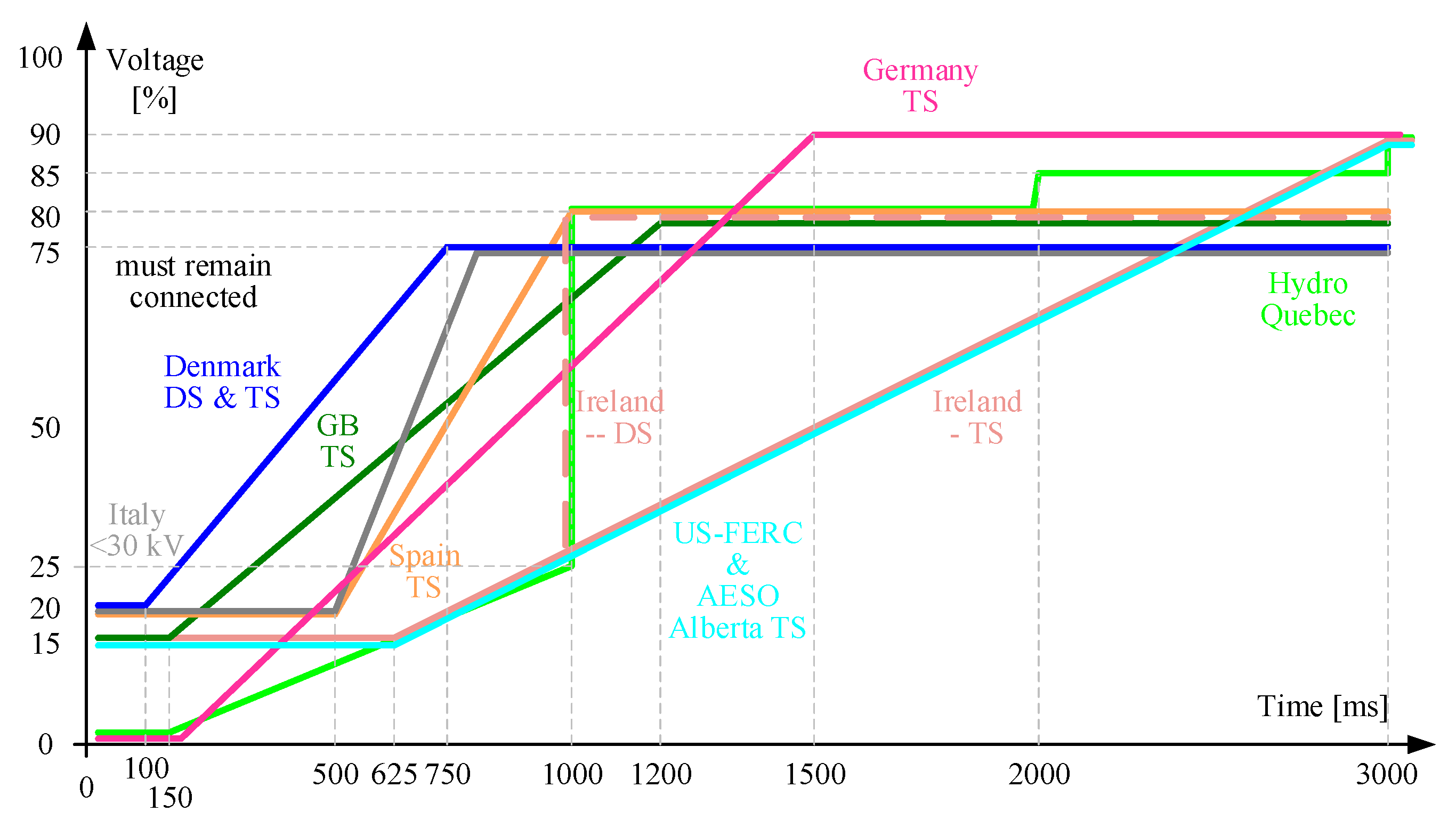
In
Figure 1 a summary of the most relevant GCs given by the respective distribution network operators is presented. The control of the grid interfaced converter must fulfill the specified characteristics at any time, and most importantly the two main requirements: stay linked (for a requested amount of time) to the grid during faults and sustain the voltage at the point of common coupling (PCC).
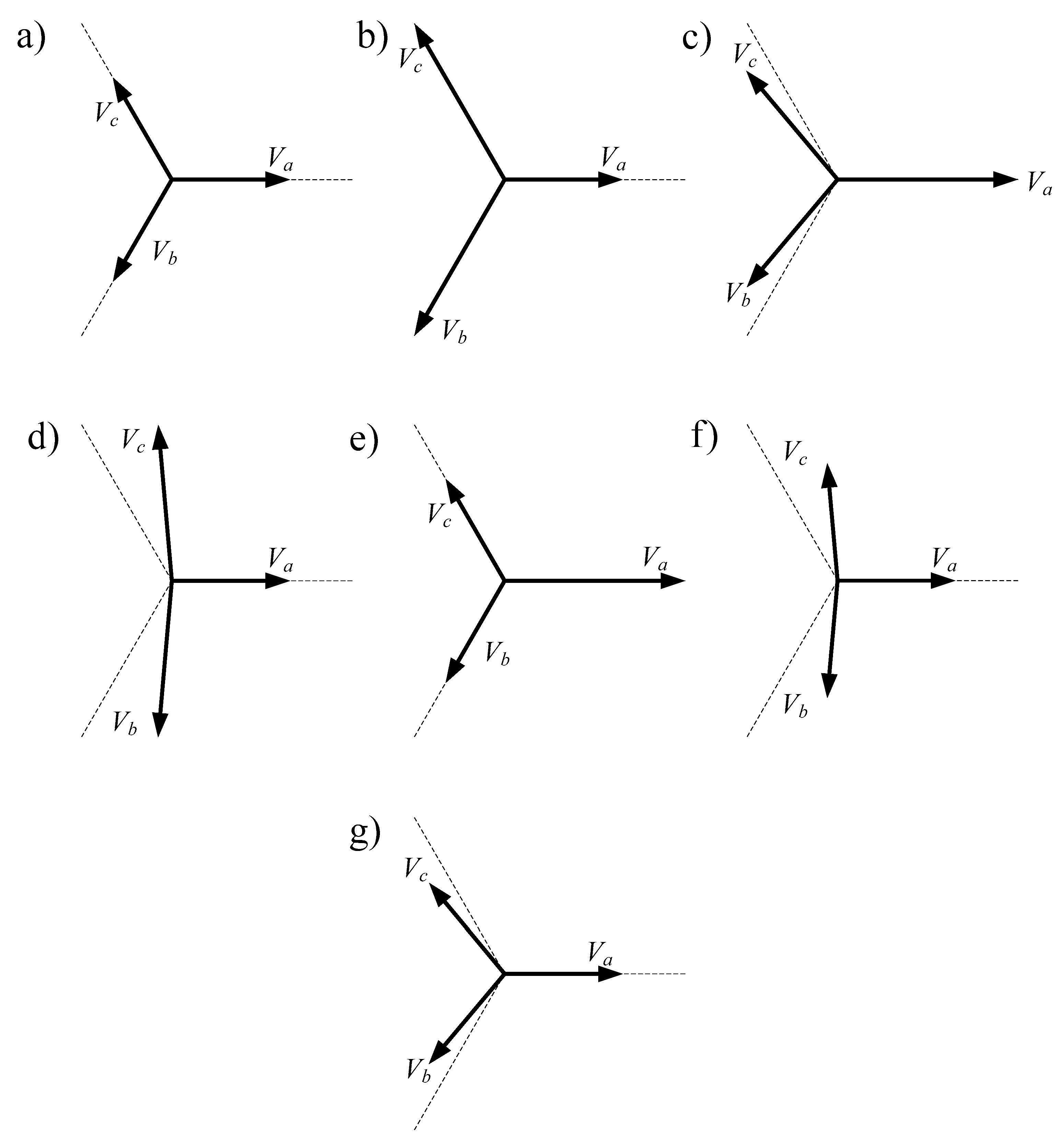
Essentially, all faults can be characterized as either balanced or unbalanced; thus, the symmetrical components classification appears to be the most natural. However, due to comprehension complexity, this classification is rarely used since it is impractical for implementation. The ABC classification of the voltage asymmetry considers the voltage vectors as shown in
Figure 2.
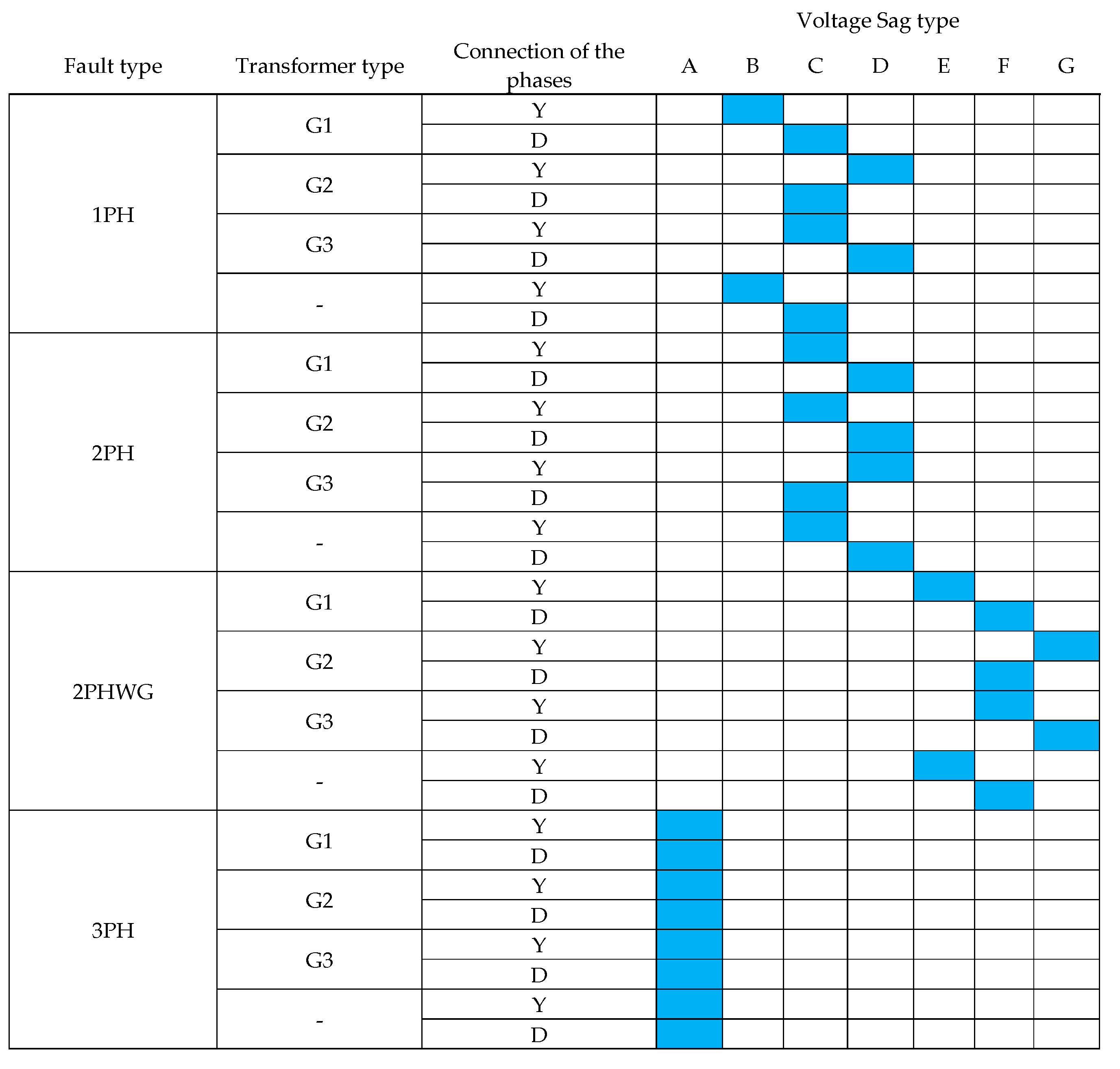
Furthermore, according to the factors of the origin of the fault, the voltage can be classified by the manifestation as presented in
Figure 3. This classification considers the following fault types: 1 phase (1PH), 2 phase (2PH), 2 phase with ground (2PHWG) and 3 phase (3PH). Additionally, the classification also considers system topology, i.e., transformer types G1 (Y
ny
n), G2 (Dd, Dz, Yy) and G3 (Dy, Yd, Yz), as well as the connection of the consumer (star delta Y-D).
As presented in [
6], the classical control technique has no issues when dealing with the balanced (A type) faults. The classical technique can have different levels of success when dealing with other fault types, ranging from inadequate power control to complete lack thereof. In that regard, the authors in [
6,
32] have proposed using a new DSC based technique for the control of the inverter under unbalanced voltage conditions. The DSC based technique, unlike the classical, can achieve full controllability of the output currents even during the most sever grid faults (i.e., voltage sag with phase shift).
When controlling the power electronic converter under asymmetrical faults there are 4 total degrees of freedom, considering both direct and inverse sequence of the currents (voltages sequences also exist but are not controllable by DER). In that regard, and following the instantaneous power theory given in [
33], there referent values for the individual sequence currents in synchronous reference frame can be calculated from:
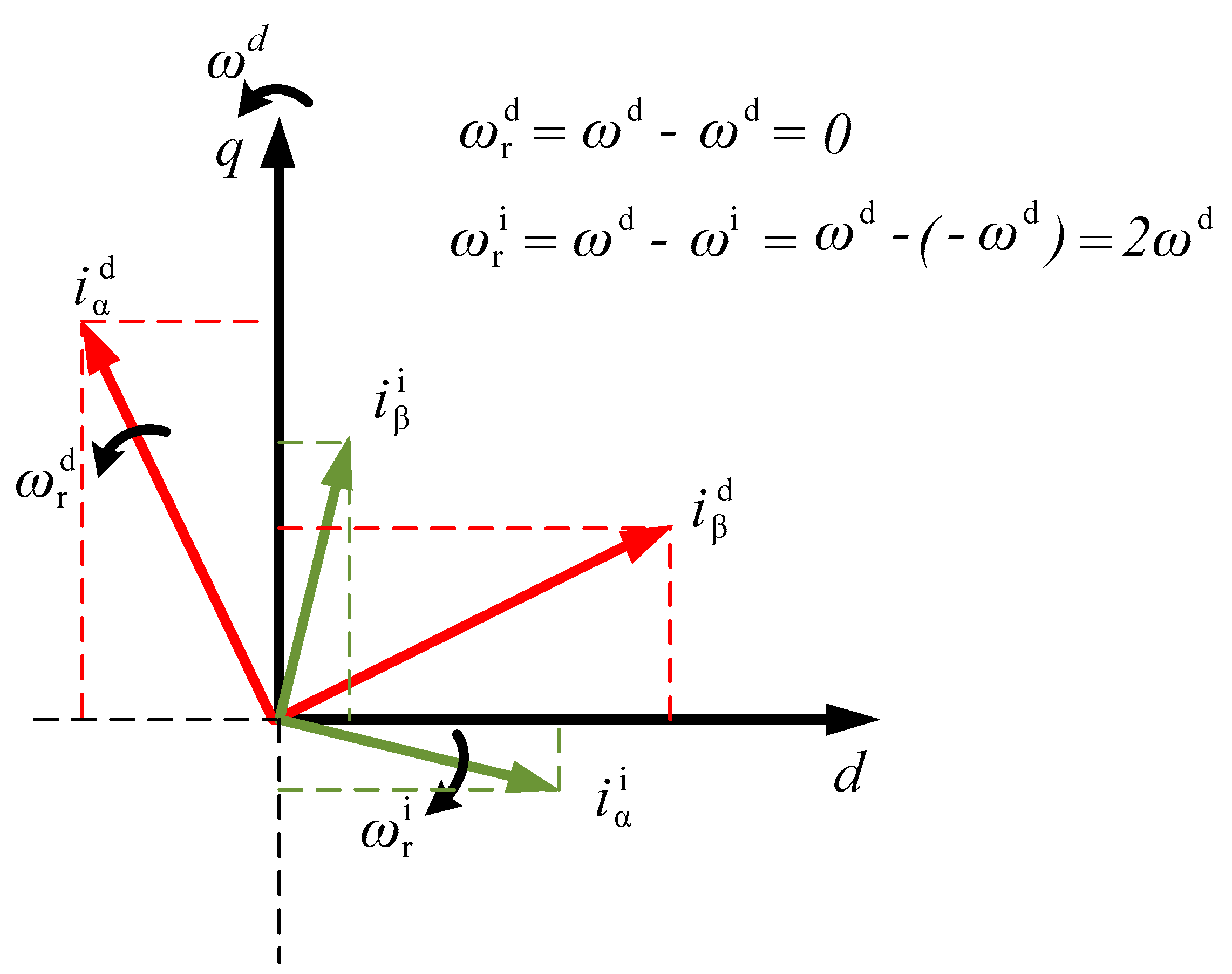
However, even with the proper calculation of the current reference values using the inverse of any of the regular voltage submatrix, the decoupled control in the synchronous reference frame (given the relevant direction) is not easy to achieve. Furthermore, multiple synchronous rotating reference frames can be used [
34], but the cross-coupling component is not easily dealt with. As demonstrated in
Figure 4, it is not completely possible to eliminate the inverse component from the direct current values (and vice versa) leading to the time dependent values in otherwise constant frame of reference.
When direct and indirect sequence Park transform is applied to asymmetrical currents given by the following Equation:
the following results are obtained respectively:
The classical technique current controllers will enhance the negative sequence current components in the stationary reference frame, thus leading to very high fault current peaks. With the use of DSC strategy in order to decouple and isolate the negative sequence component, the classical inverter control for the inverter can be enhanced. The use of the DSC method is common in unbalanced power systems for the separation of the phase-sequences [
35]. It is usually defined using the complex notation of the stationary reference frame as:
However, its implementation in the synchronous rotating reference frame is much simpler when real time control is considered [
6]. When the proper alignment of the reference frame is achieved using an improved PLL technique, the values for the active and reactive power can be calculated by:
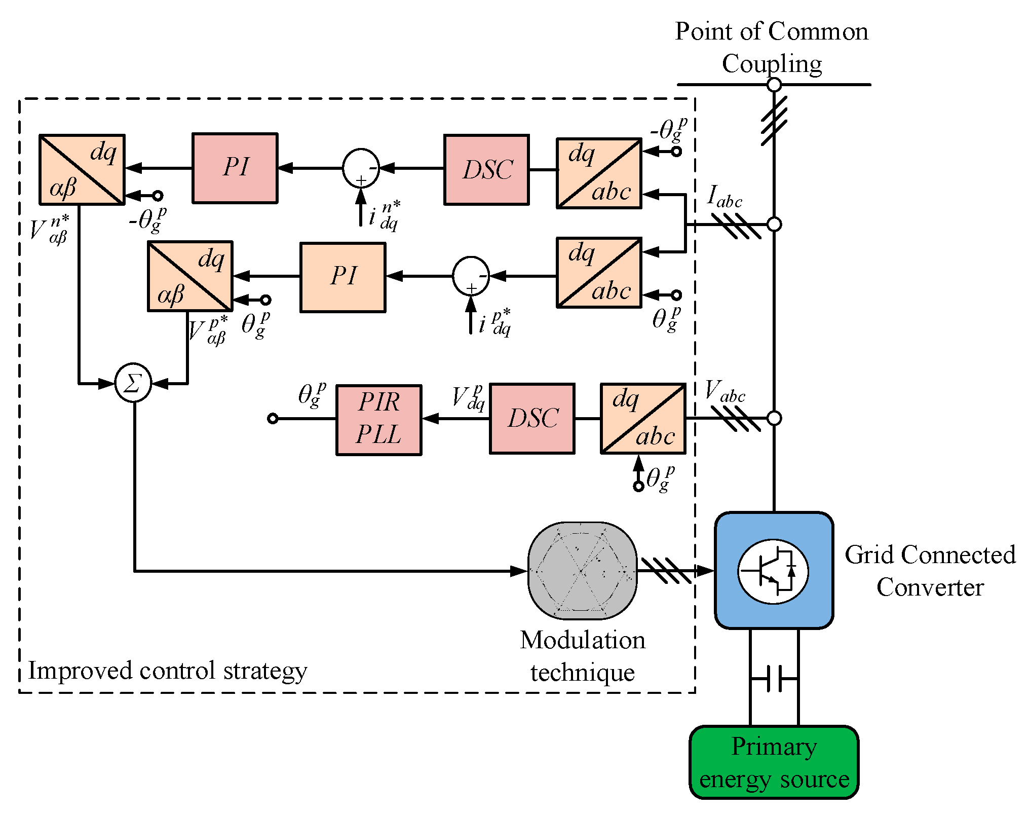
The basic outline of the improved control methodology based on the DSC technique is given in
Figure 5. The proper alignment of the reference frame can be achieved using different well known PLL structures (EPLL, SOGI-PLL, Adaptive-Notch PLL, SOGI-FLL etc.) proposed in the literature [
25,
28]. This paper is using the DSC based PIR (added resonant segment in loop filter) PLL structure, whose main benefit is the simplicity of implementation, while it offers satisfactory dynamic performance during synchronization to the asymmetrical voltages. The current controller parameters in the negative sequence can be derived by modified symmetrical optimum given in [
32] by:
when the delay in the negative sequence current (
Tg) is considered.
The controller in the negative sequence will have little influence during balanced grid faults, but may sometimes mitigate some harmonic content due to its frequency response and result in slightly lower peak currents.
The study of initial fault response of the inverter operated by the technique based on the DSC is particularly important, even more so when modelling and predicting the behavior of DERs is considered. This is also very interesting for studying the setting of distance protection [
4].
3. Results
In order to fully examine such behavior, an advanced rapid fast prototyping station for DER integration testing, developed at the Faculty of Technical Sciences, University of Novi Sad, Serbia is used [
30,
36].
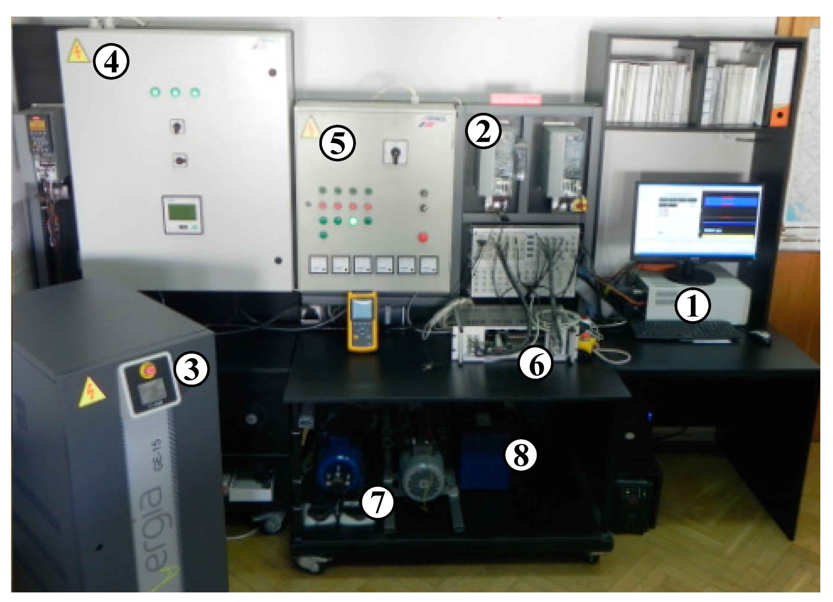
The test station represents a grid connected converter for DERs integration model scaled in power. The hardware consists of state-of-the-art components for real-time control of power electronics based electrical drives. In
Figure 6, the main components of the system can be observed. Designated by ①, the main control unit is the dSPACE processor board. It is a high-performance control hardware that executes the designated algorithm for the control of the grid connected converter. The power electronics device that operates as a GCC is designated by ②. Different voltage faults for testing are provided by grid emulator ③ that is connected at the point of common coupling. Switching and protection of the equipment if offered by ④ and ⑤. Additionally, since the station is highly modular, this equipment acts as a selector for the current test setup [
37]. Signal adjustment for data acquisition and control is achieved using the adapter block marked with ⑥. To offer the flexibility for the testing of different DERs the system integrates electrical machines ⑦, torque-controlled drives ⑧ and DC/DC ⑨ converters [
29].
The grid connected converter control algorithm based on the mitigation of the negative sequence currents within this experiment, is implemented using the theoretical background from [
32], while the comparison was made to the classical control technique stemming from instantaneous power theory given in [
33]. The voltage control is implemented in the synchronous reference frame, with the alignment to the positive sequence
d-axis.
In order to examine the initial fault response of the proposed algorithm and to derive the relation to the classical technique, a number of experiments are performed. These experiments have been conducted for different voltage states, including the symmetrical voltages (balanced grid fault), as well as asymmetrical voltages (unbalanced grid fault).
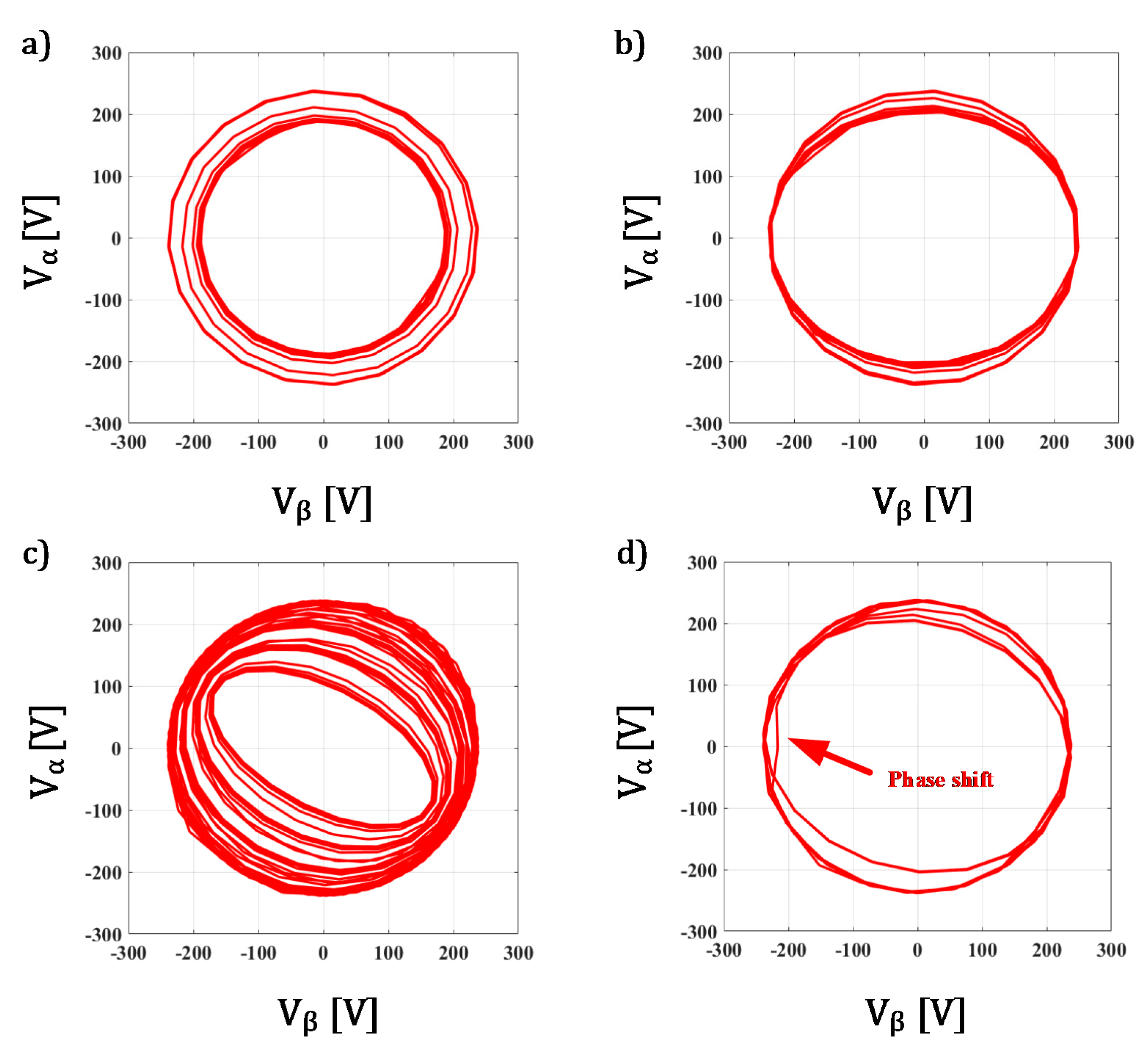
Figure 7 shows the voltage space vector for the different voltage states used for the following experiments. Every voltage vector representation has a distinct shape, while the width of the shape will be determined by the level of the voltage dip.
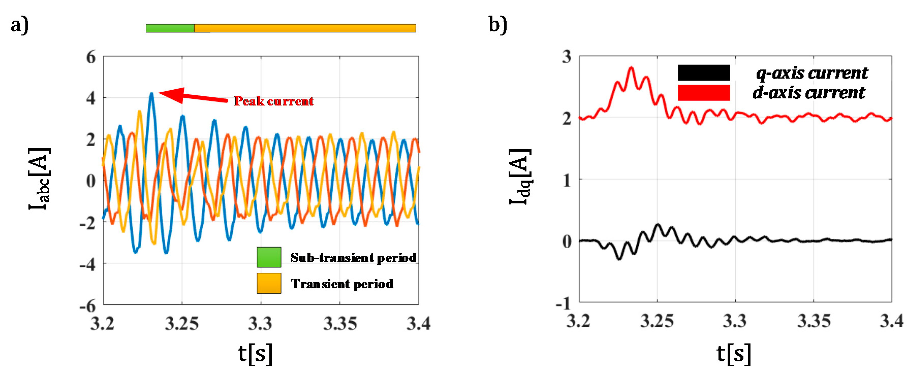
For the first experiment, in order to establish the benchmark for the DSC based technique the, it was tested against the balanced three-phase fault (with symmetrical voltages). The technique has been tested for two different sets of current controller parameters: one that is calculated according to theory and the other that is equal to half that. The current was set to the rated value of 2 A for both tests, and the voltage dip of 20% has been emulated in all three phases simultaneously. The results for the first experiment may be perceived in
Figure 8 and
Figure 9, where the current waveforms,
d- and
q-axis currents are shown. As can be observed from the
Figure 8, the response of the DSC based technique for mitigation of the negative sequence components has a very good response during balanced grid fault with the initial current peak at 5 A and the length of sub-transient period somewhat less than 20 ms. Prior to the fault, and in the transient period the current is successfully controlled to the rated value (2 A). The peak current value is expected and in full accordance with the values offered by the classical technique and presented in [
29]. Additionally, these values fully comply with the relevant reports for the fault response of commercially available technologies presented in [
14,
15] where initial fault response can be characterized by up to 5 times the rated currents. Furthermore, as in [
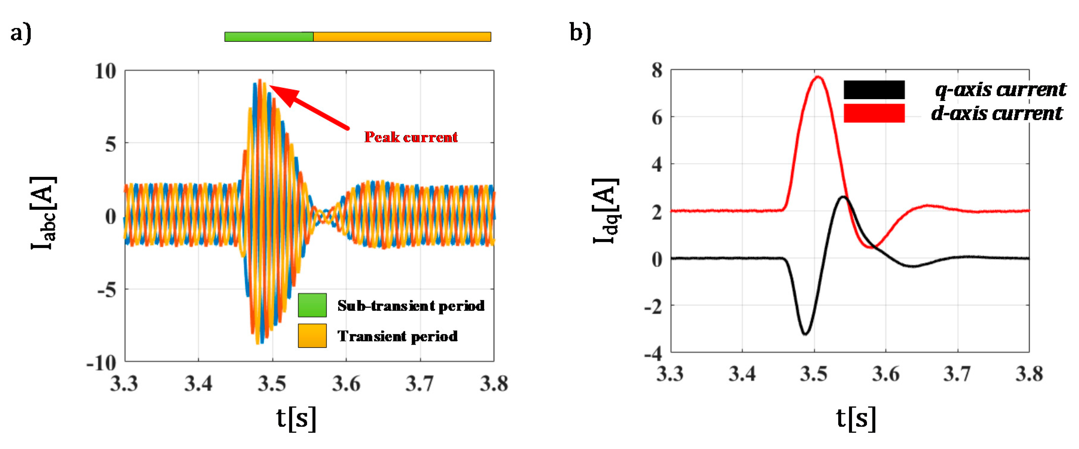
29], the controller parameters will significantly influence the initial fault response. The detuning of the parameters by 50% increased the peak current by almost 2 times to about 9 A.
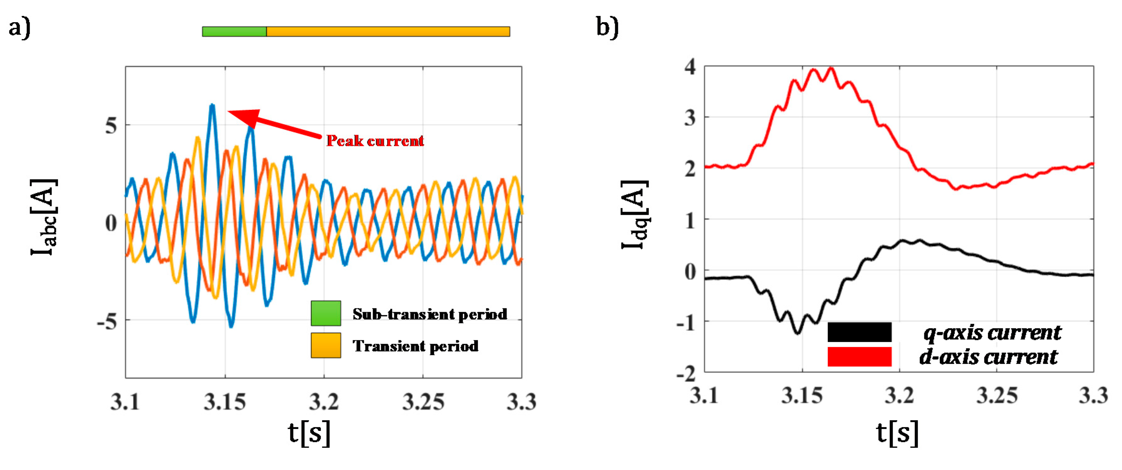
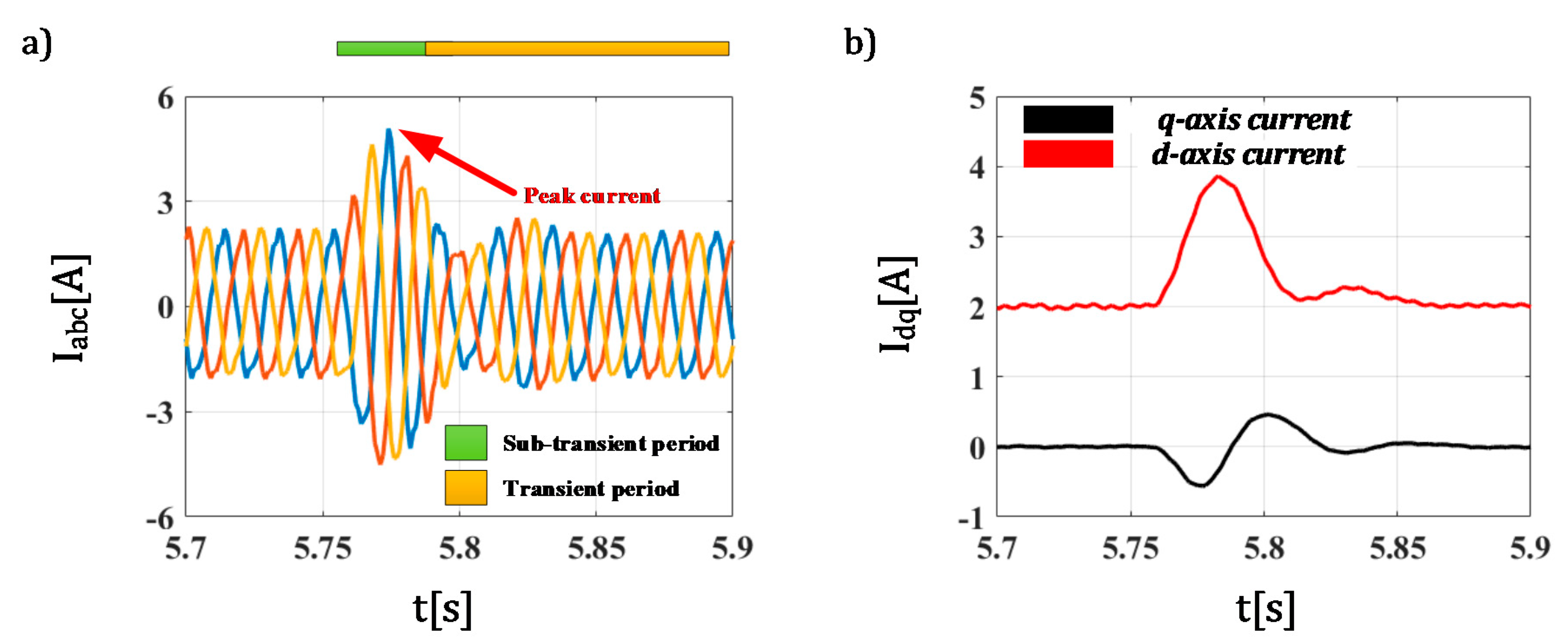
The same behavior, in regard to the controller parameters, was observed for unbalanced faults that resulted in one phase voltage dip of 20%. As previously proven in [
4], the classical control technique without the mitigation of the negative sequence components is not equipped to deal with unbalanced faults, with voltage dips as low as 30% can cause protection tripping. The technique that uses the DSC method for mitigation of negative sequence currents will be tested under this unbalanced fault with 2 different sets of current control parameters (same as previous case). The results are shown in
Figure 10 and
Figure 11. The same behavior in regard to the influence of the controller parameters can again be observed, with the peak current again almost double for the weaker parameters. Additionally, we can see that the length of sub-transient period has increased. When optimum parameters are considered, the peak current is slightly lower for the one phase voltage dip with the value of just about 4 A in total. The duration of the sub-transient period for the unbalanced fault has slightly increased, but it is still within the two current periods (we see here that it is just a little higher than 20 ms). In that regard, careful consideration of the control technique and parameters can reduce the peak current of the converter during faults. For future experiments, the optimal current control parameters will be used to investigate the initial fault response for different types and levels of voltage dips.
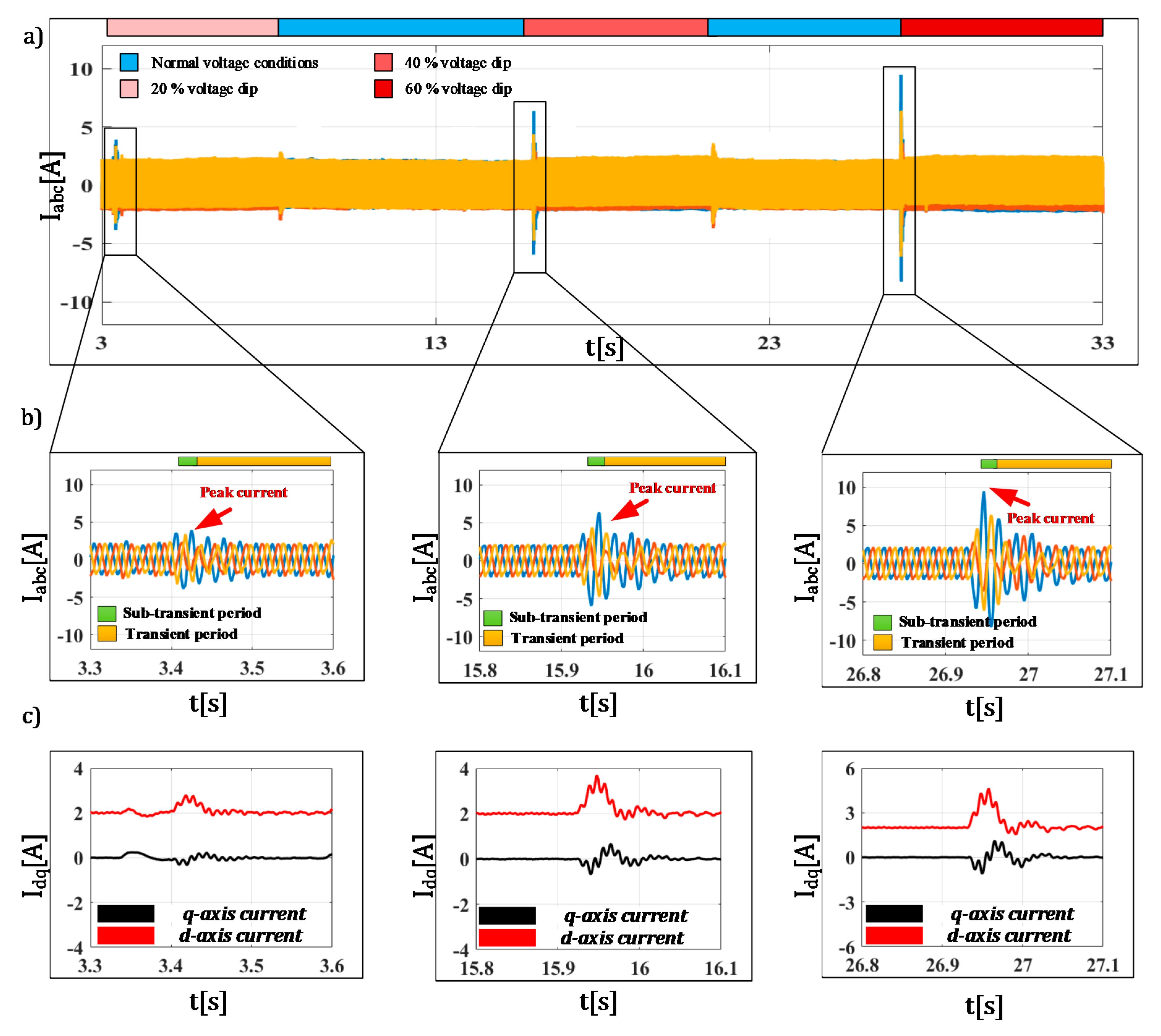
For the respective control technique, the following experiments were designed to investigate the fault current peak value during the sub-transient period for the different types of voltage faults and voltage dip values. In
Figure 12 the initial fault response for the converter can be observed for the unbalanced faults that manifest with one phase voltage dip.
During the experiment, the grid connected converter was operated continuously with the d-axis current set to the 2 A rated value. At certain time instances (3.4 s, 15.9 s and 26.9 s) the voltage variation (dip) was triggered at different levels (20%, 40% and 60%, respectively). After some time, when the converter has entered a transient state, the voltages were restored to the normal values cycling through the pattern. Each time the voltages altered the value we can observe similar transition period; however, the transition from fault state to normal voltages is usually characterized by lower peak currents. The peak currents evidently increase with the depth of voltage dip as expected. The values of the peak current for the 20% of voltage dip is 3.8 A, which is slightly lower than in case of three phase voltage dip (compared to the response in
Figure 10). As the voltage dip level is increasing, so does the fault current peak to 6.35 A and 9.46 A, for the 40% and 60% voltage dip, respectively. It can easily be concluded that this is still within the expected range of results presented in [
8,
14,
15]. The negative sequence component has successfully been mitigated even during the sub-transient period, which is evident by the absence of oscillation within d- and q-axis currents. The length of the sub-transient period is virtually not impacted by the depth of voltage dip, since we can observe similar (almost identical) durations for all three cases. The length of the sub-transient period can be considered as one current period, i.e., 20 ms long.
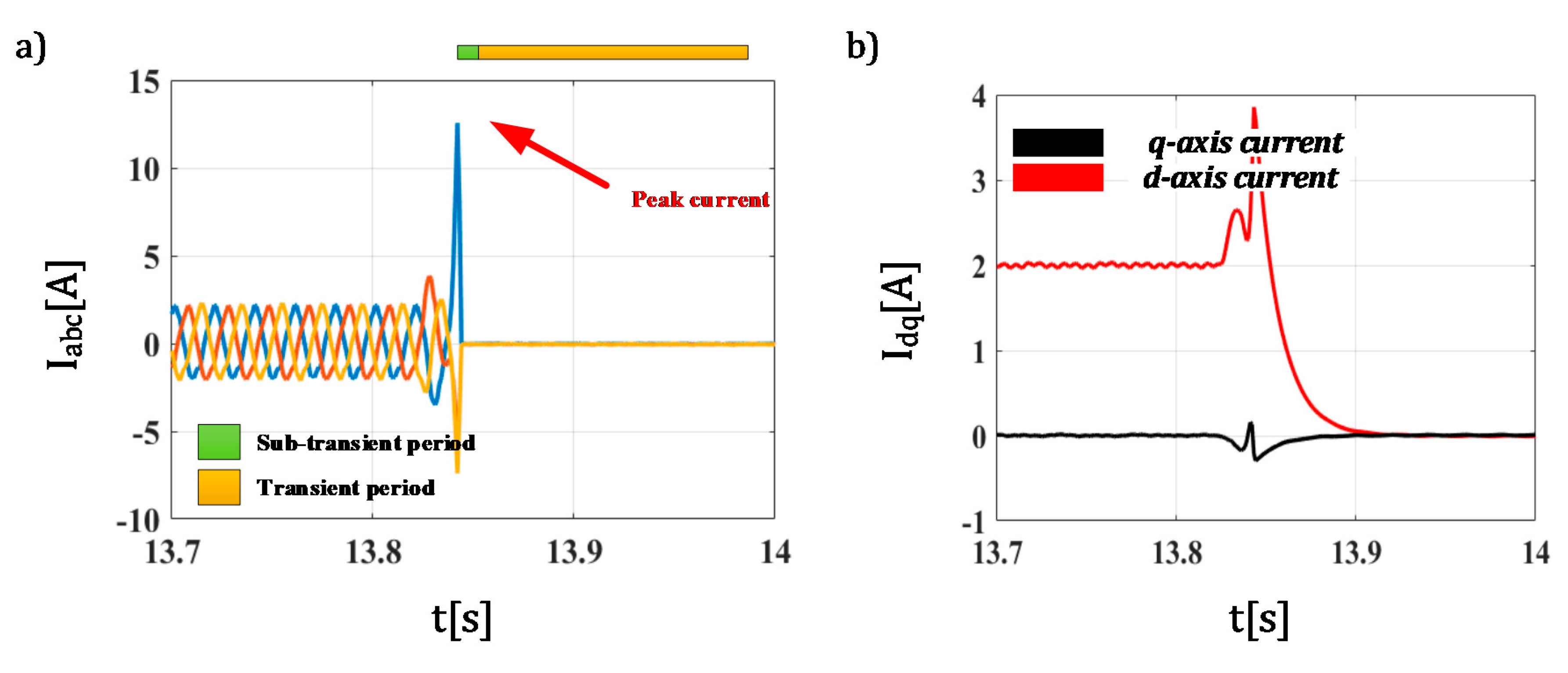
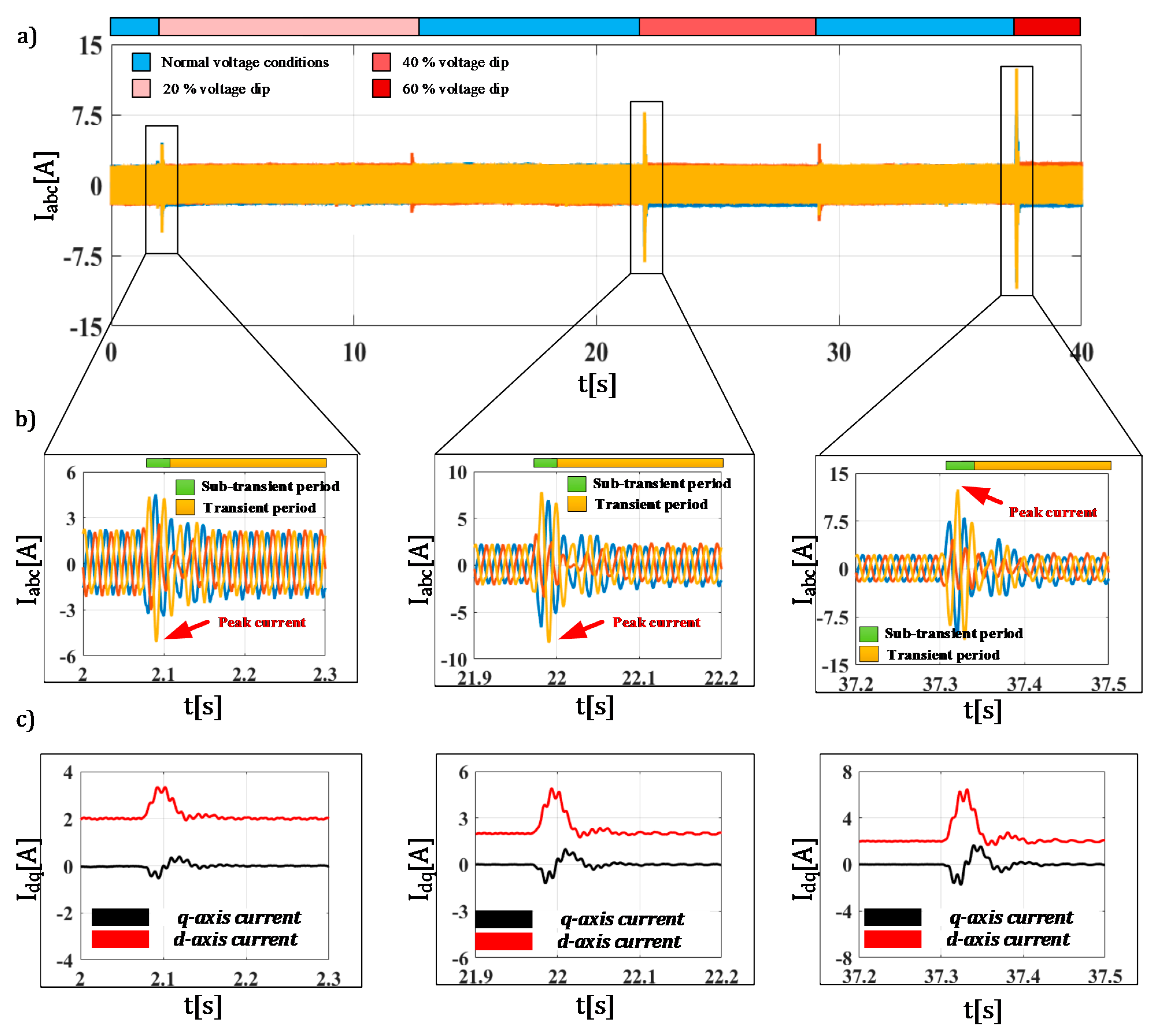
Aiming to further verify the initial fault response of the algorithm, the same experiment was repeated for the two-phase voltage dip. The results for this experiment are presented in
Figure 13, where a similar behavior pattern can be noticed. Obviously, as the depth of the voltage dip increases, the peak current is also increasing, while the return to normal voltage state is followed by much less impact.
The voltage dips have occurred in 2 s, 21.9 s and 37.3 s for the 20%, 40% and 60% voltage dip, respectively. The value of the sub transient current has peaked at 5.08 A, 8.21 A and 12.43 A in relevant order. We can still observe that the mitigation of negative sequence is successfully achieved. This indicates that the two-phase faults are more critical in term of initial fault response, since they can have slightly larger peak current component during the sub-transient period. The length of the period is virtually unaffected.
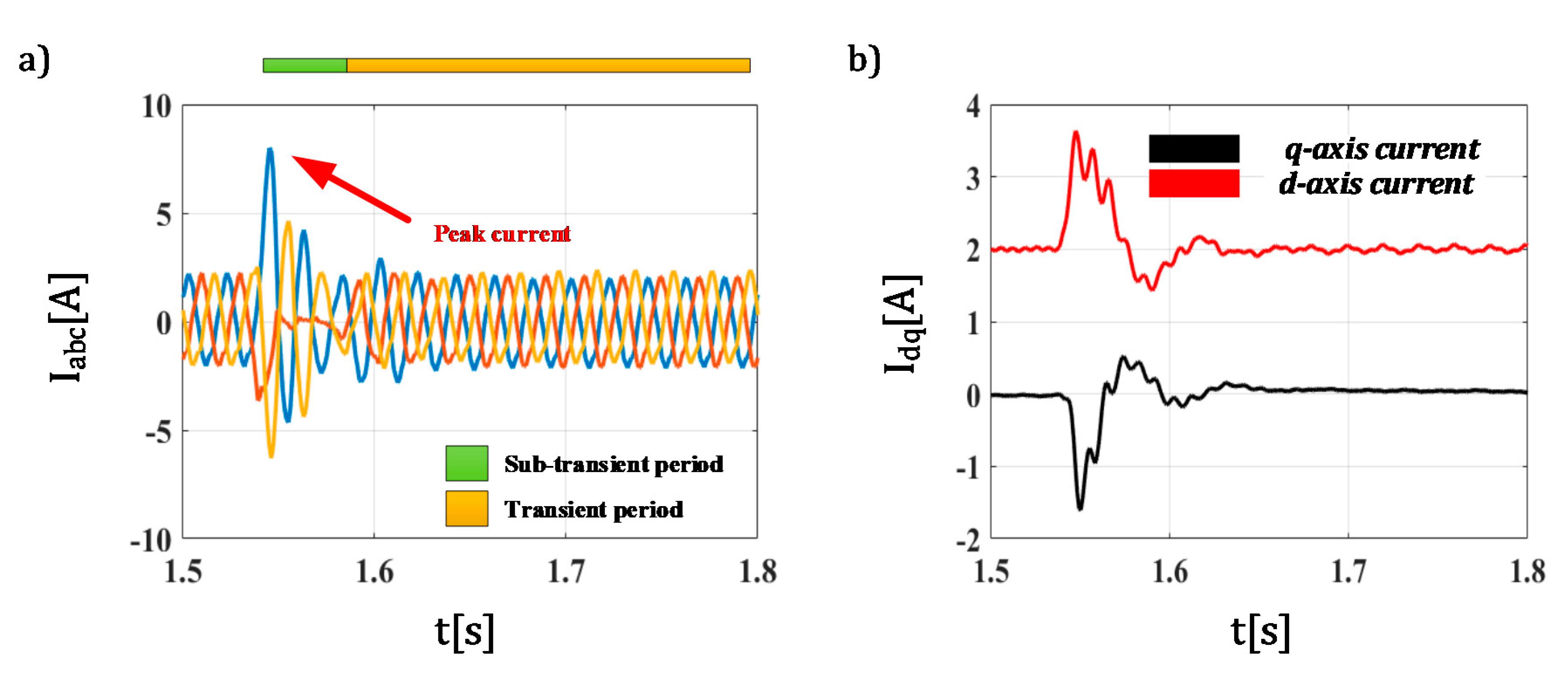
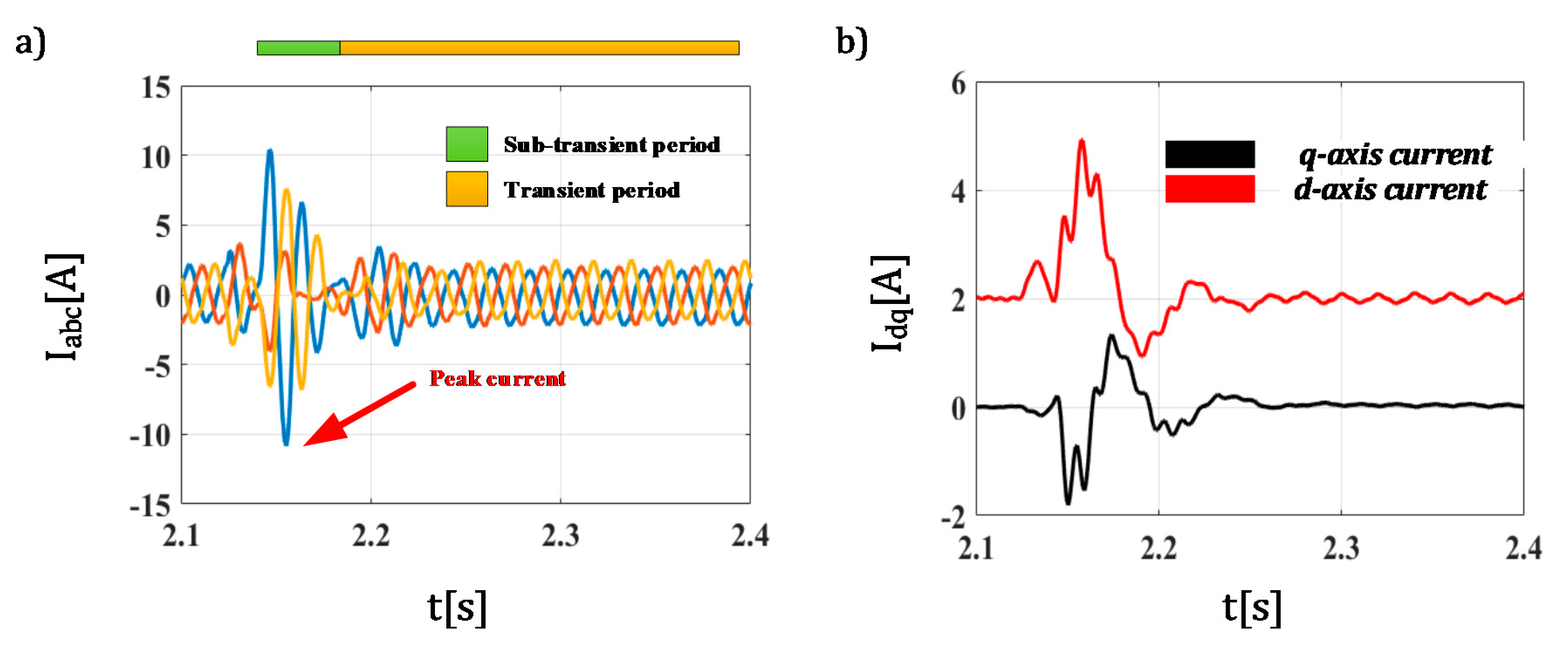
For the last test, the algorithm was verified against a one phase voltage drop with 10 degrees phase shift (in the same phase). The values of the voltage dips has remained the same with 20%, 40% and 60% respectively. Unfortunately, the technique has hit its absolute current limitation for the 60% voltage dip with phase shift (tripping of protective equipment), indicating that the phase shift component influences the fault current peak significantly. The respective results for these results are presented in
Figure 14,
Figure 15 and
Figure 16 in order of the magnitude. In the first two figures, we can see that the peak current values have been at 8 A and 10.84 A, for the voltage dip of 20% and 40%, respectively. The controller was able to preserve full controllability of the system, and the same would be true for the 60% voltage dip with phase shift, if such current would be allowed by the hardware. We can see that, in addition to the significant increase in peak current value, the length of the sub-transient period has also increased, mostly attributed to the phase shift component.
4. Discussion
The sub-transient response of the grid connected converter is obviously an important subject when analyzing its operation, especially during grid faults. Obviously, the output current of the converter can be controlled to the referent value in transient and steady state operation, where the value of the current can be considered by the relevant GC. However, during the sub-transient period the proposed current limitation (1.5 time the rated value) can only be achieved within a handful of operating conditions even for the classical technique as shown in [
29]. This has been further confirmed by relevant reports such as [
14,
15], that show the peak current to be significantly higher (about 5 times the rated value). Moreover, when unbalanced grid faults are applied to the converter controlled by the classical technique, sub-transient currents can trip protective devices even for voltage dips as low as 30%.
In that regard, the improved DSC based technique is implemented in order to preserve the control during unbalanced faults, and thus fulfil the requirement for the FRT capabilities of converter interfaced DERs during unbalanced faults with asymmetrical voltage conditions. The improved technique has been proven to have similar operational characteristics in regard to the classical technique during balanced faults with symmetrical voltages. This can be seen even for the initial fault response of the converter (
Figure 8), where the peak current of the improved technique was similar to the values reported in [
29].
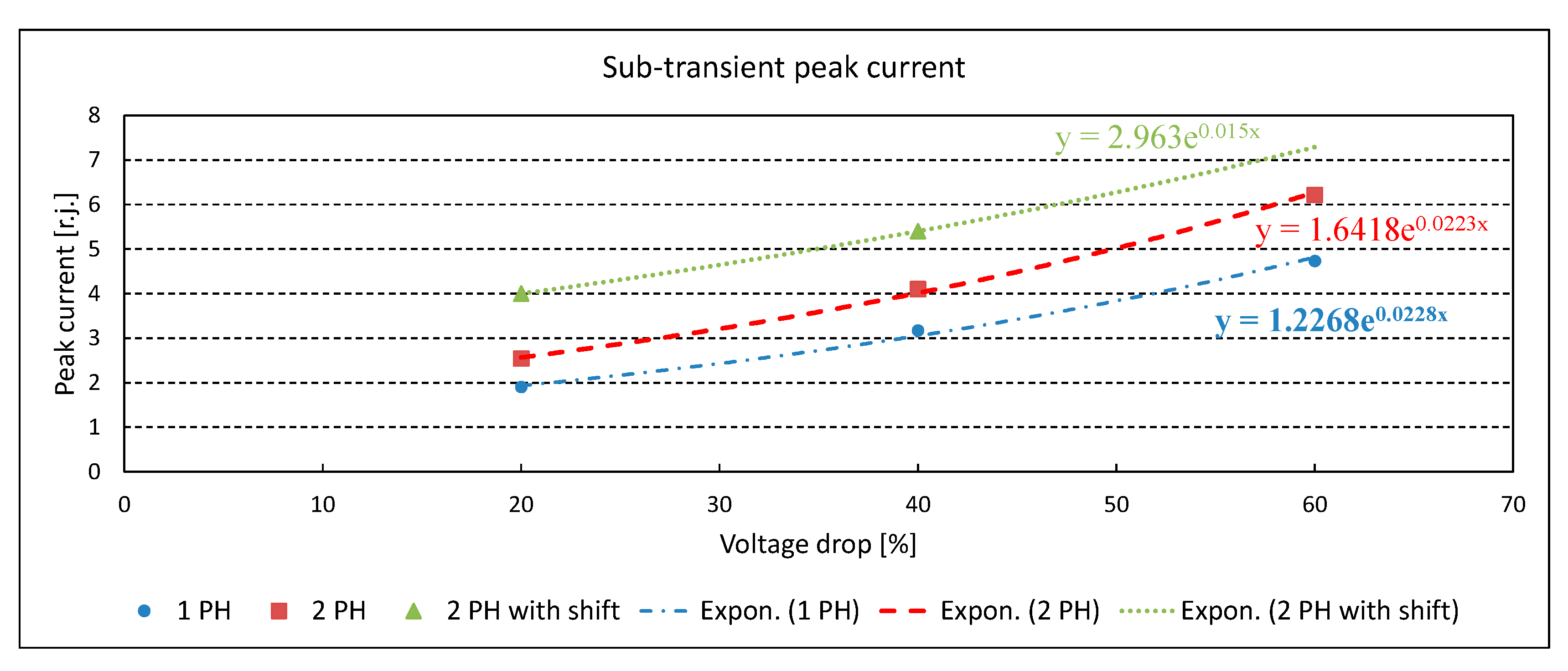
However, when operation under asymmetrical voltages is considered, there is a significant discrepancy between the classical technique and the technique tested within this manuscript, since the classical technique never exists in the sub-transient state (cannot regulate the current values due to negative sequence component). The DSC based technique is capable of handling the proposed 1 ph voltage drops, while retaining the controllability of the current and offering the possibility for implementation of FRT algorithms. The value of the peak current is proportional to the voltage dip depth, as proposed by the literature, with the peak current to voltage dip ratio, slightly lower than for the balanced type faults. This value of the current, relative to the voltage dip, is given in
Figure 17. This graph can be used to model the initial fault response of the inverter controlled by the DSC under unbalanced grid faults.
On the other hand, two phase voltage dips do present with much higher values of the peak current for the same amount of voltage dip, with the sub-transient current differ for about 25% of the value. The most critical fault is the voltage dip with phase shift, where significantly higher currents can be observed in the sub-transient period. The value for the peak current in case of the phase shift is 2.1 times higher than in the case of a regular one phase voltage dip. Compared to the two-phase voltage dip, the phase shift case has 1.57-time higher peak current.
Considering the experimental verification, it can be concluded that the sub-transient response of the grid connected converter can be quantified for modelling by well-known mathematical apparatus (linearized or exponentially characterized); however, different types of voltage dips still need further investigation. Additionally, the peak current is limited, but this limit can be significantly higher than 1.5 of the rated current, especially during unbalanced faults. Obviously, the rate of change of inrush current to the voltage dip is not linear, though it can be linearized by parts (in certain ranges of the voltage drop level) to satisfactory precision. Special attention needs to be given to the voltage variations that include the phase shift, since the phase shift can have significant reflection on the sub-transient current.
The duration of the sub-transient period was not significantly impacted by the type or level of voltage drop, excluding the phase shift case where the duration was slightly increased.
5. Conclusions
The proliferation of DERs in the upcoming distribution system will inevitably cause the power system to undergo a change to a more decentralized counterpart, making way for a completely new concept of active distribution systems. In the new active distribution systems, a grid connected converter will become one of the main elements. Considering the importance of the fault state calculations within the distribution system, the operation of the converter under faults needs to be carefully examined. The classical control technique, while very simple for implementation, lacks the ability to control the set point currents during unbalanced conditions with asymmetrical voltages. In order to resolve this, a technique based on the DSC algorithm for mitigation of negative sequence currents is investigated. Relevant technique is capable of attaining suitable steady state performance under asymmetrical voltages and offer the FRT capabilities to the converter. While steady state performance is of utmost importance, the initial fault response of the inverter under such control technique needs to be investigated in order to develop the appropriate model for the fault state calculation (solvers) in the ADS and micro-grids.
In order to experimentally investigate the initial fault response of the inverter controlled by the DSC technique, authors have used an advanced laboratory setup for rapid prototyping of grid connected DERs. The paper investigated the sub-transient and transient periods, focusing on the peak current in the initial period. The initial response of the DSC based algorithm was in full accordance with the consideration in available literature when balanced faults are observed. For one phase voltage dip, the peak currents were slightly lower than in case of the balanced faults. The most challenging faults include the phase shift, where even the improved technique was unable to maintain operation under 60% dip with 10 degrees phase shift. The values are still limited and within the expected ranges (especially when short duration is considered) but the new technique has to be comprehensively tested for different combinations of phase shift angle and asymmetry level.


