
On the Assessment of Cyber Risks and Attack Surfaces in a Real-Time Co-Simulation Cybersecurity Testbed for Inverter-Based Microgrids


 ,
,  and
and
Abstract
:1. Introduction
- We studied the usage of ICTs and their intermittency using tailored protocols in the testbed for both the cooperative control and protection architectures of microgrids;
- We validated the modeling of physical and cyber infrastructures of the test microgrid, which provides a real-time feasibility study of cyber attacks using different vulnerable points;
- We provided both local and fully web-based remote HMI access;
- We integrated actual switches and routers which aid in studying attack impacts on real network traffic;
- We assessed vulnerability—specifically in relation to the control and protection architectures of a microgrid system;
- We presented the basic modeling of some of the attacks which can penetrate system security and affect the control and protection architectures of a microgrid;
- We demonstrated the effect of a smart attack on the test microgrid.
2. Testbed Development and Vulnerability Assessment
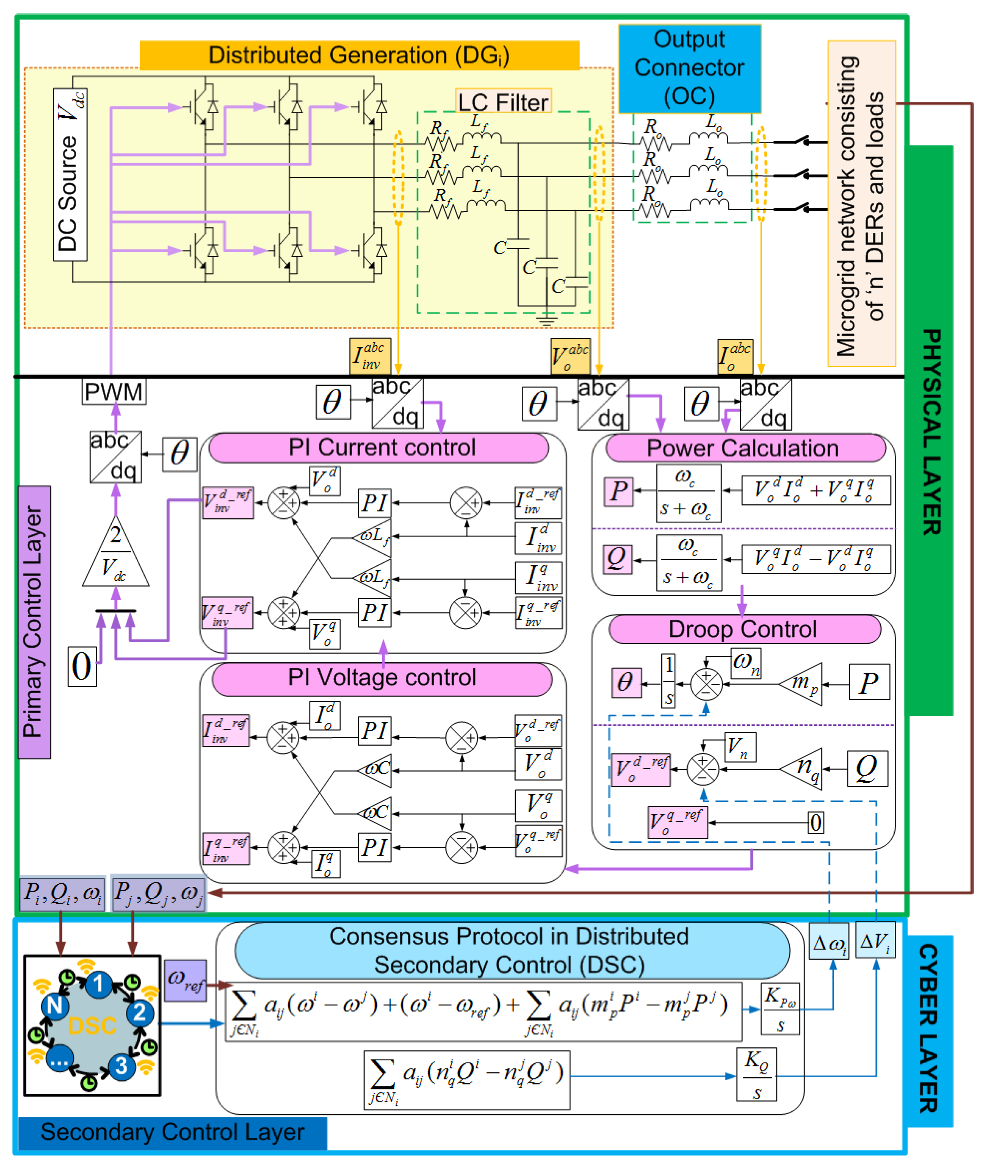
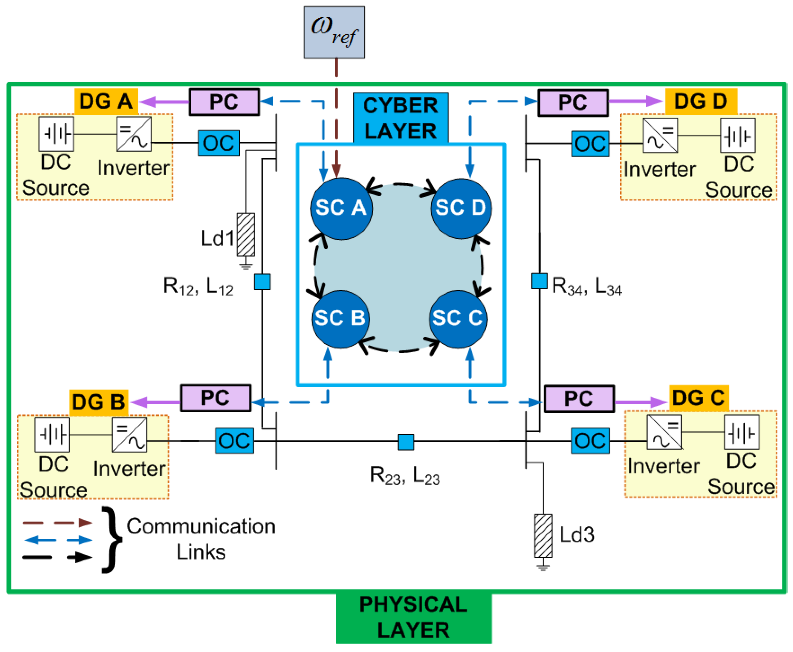
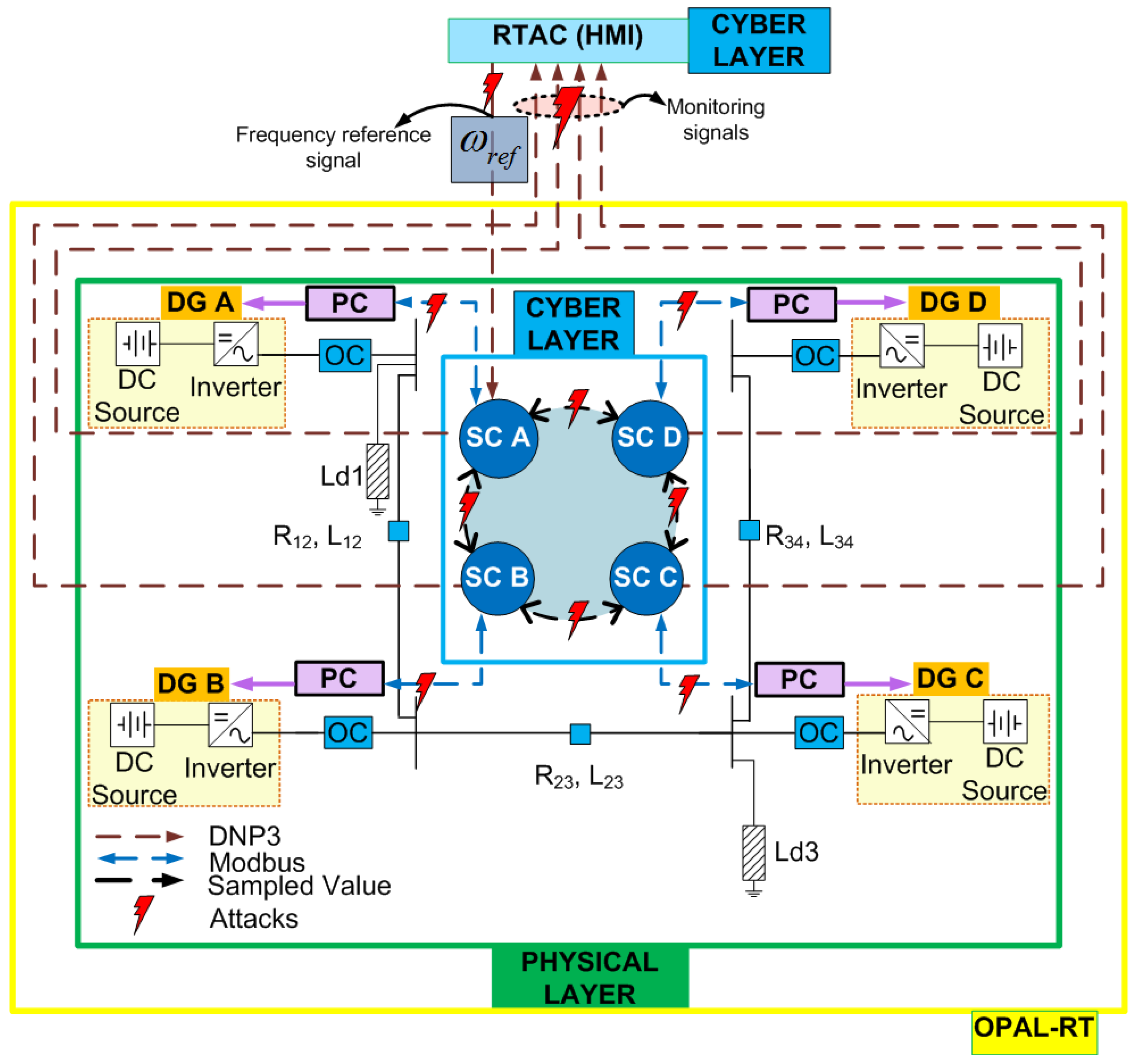
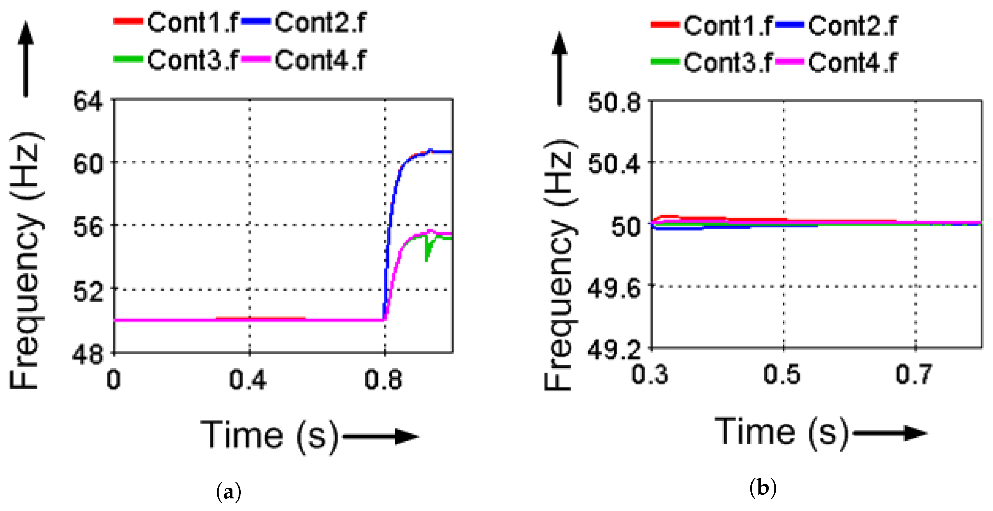
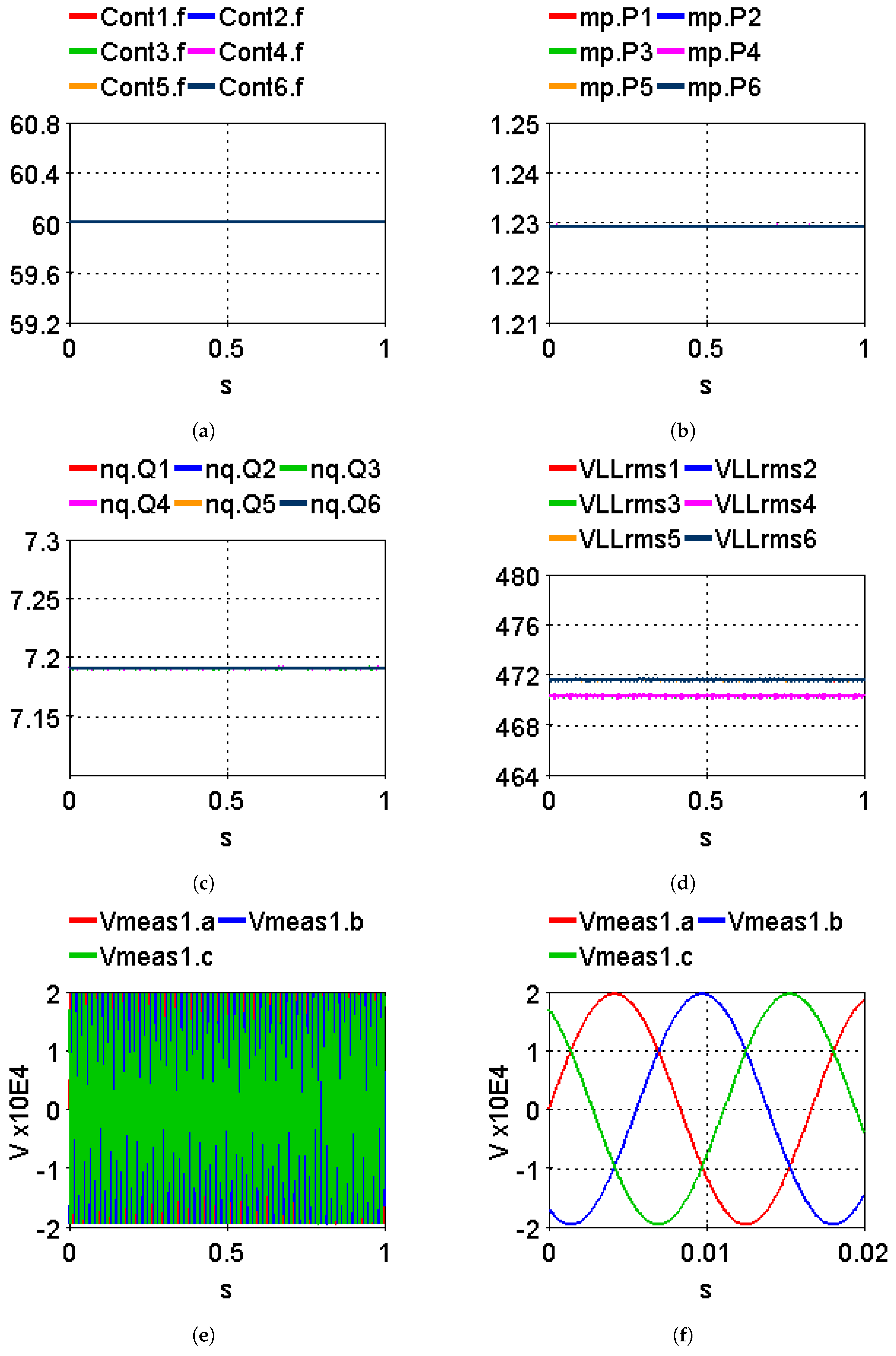
- Frequency restoration:
- Proportional active power sharing:
- Proportional reactive power sharing:where j∈. i.e., all the immediate neighbors of ith DG.
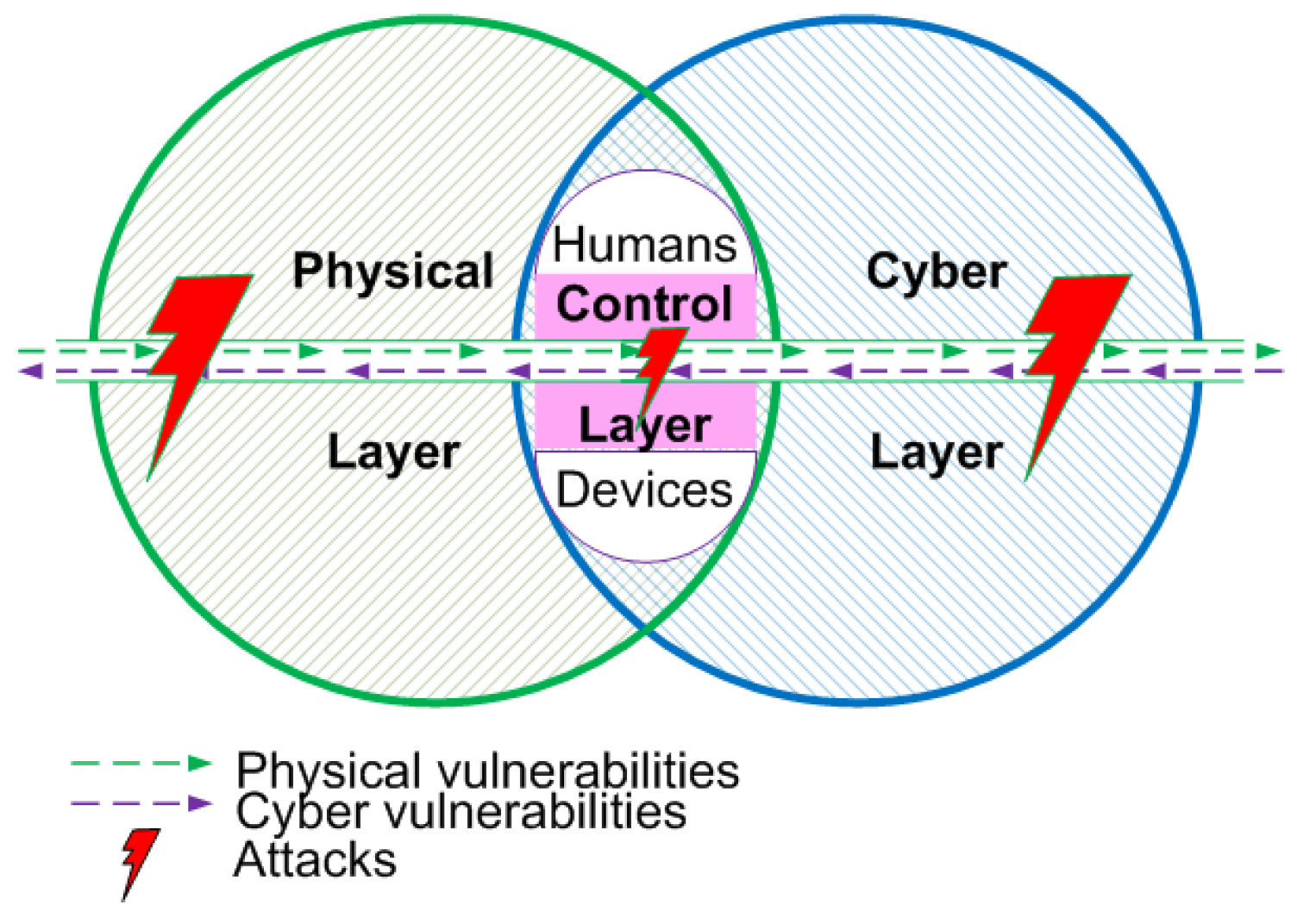
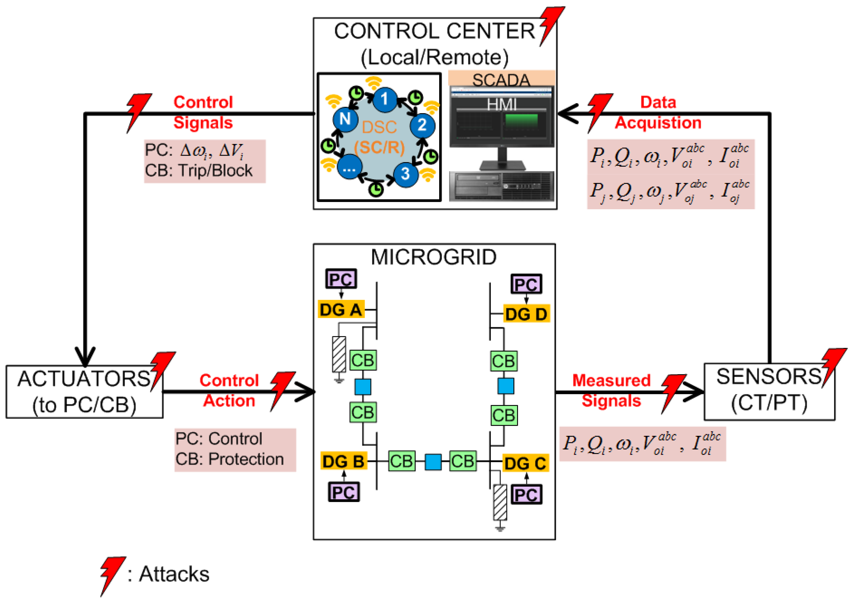
- CYBER VULNERABILITIES:
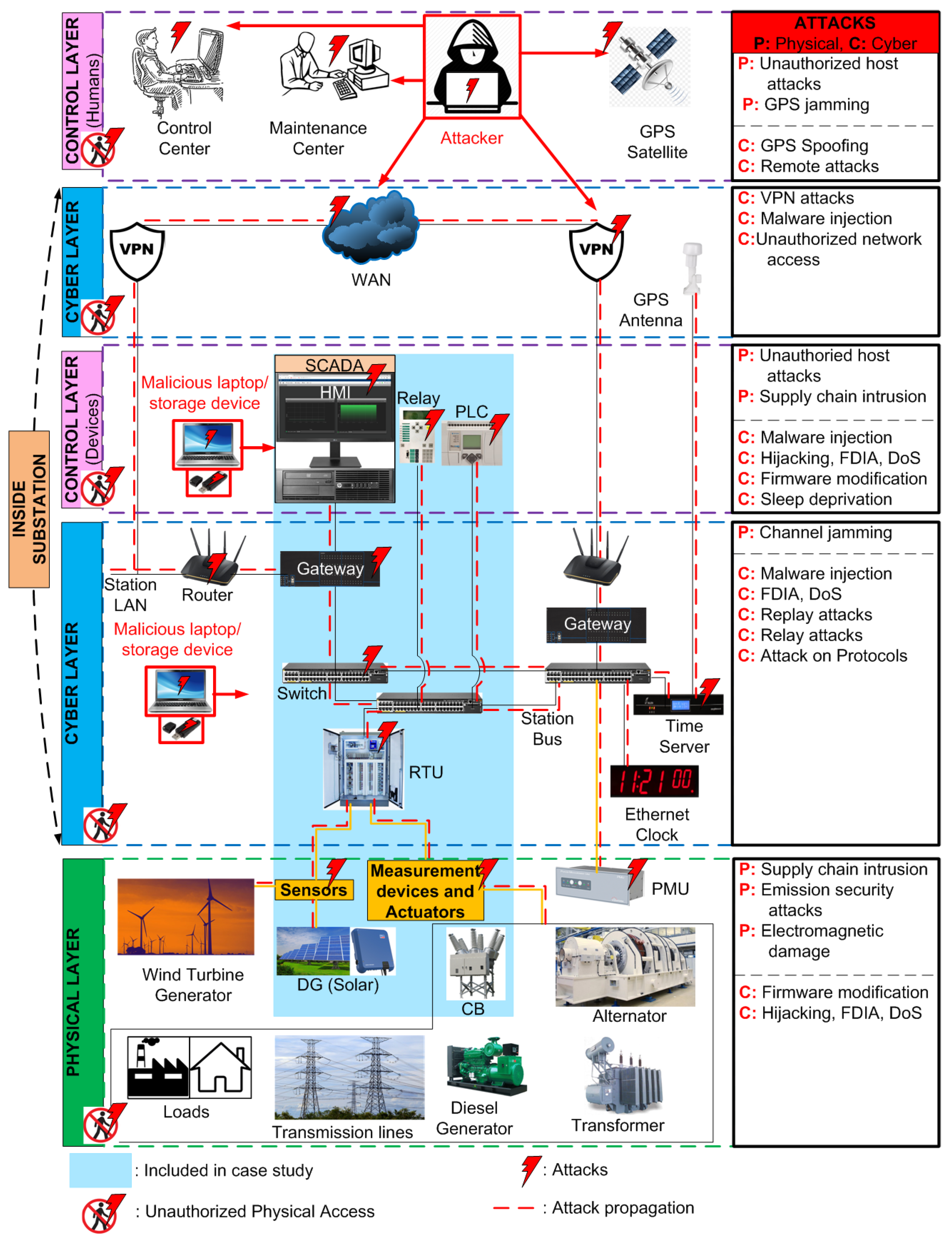
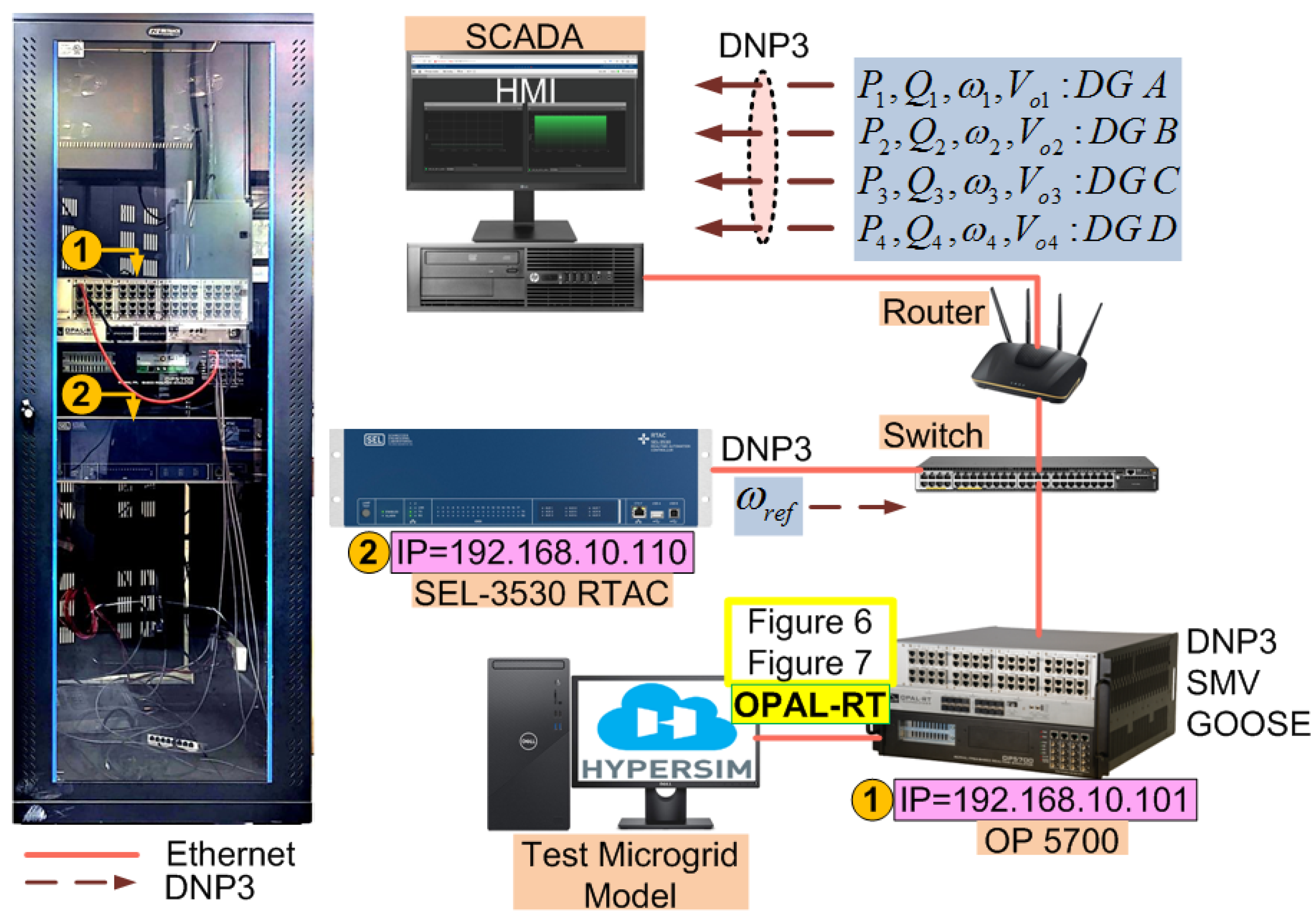
- HMI: Through this interface, the operator can monitor the dynamic changes in the network and send the command signals (if enabled). The attackers can infiltrate HMI by exploiting its software vulnerabilities from a remote site or through malware injections and disrupt the signals observed, presenting a false state of the system.
- Communication links: It can be wired or wireless and could be manipulated by attackers or distorted by the environment.
- The routers and gateways: DoS, packet mistreating attacks (PMAs), routing table poisoning (RTP), hit and run (HAR), persistent attacks (PAs) are some of the common possible attacks on routers, which either disrupt the system or inject harmful packets, helping the attackers gain access to the network. Since the gateway is a crucial link in the flow of information between different sensors, interfaces and equipment are among the main targets of attackers. DoS attacks and gaining access to the I/O mapping table to manipulate the process in order to cause disruption are among the attacks preventing operators from viewing and taking correct actions.
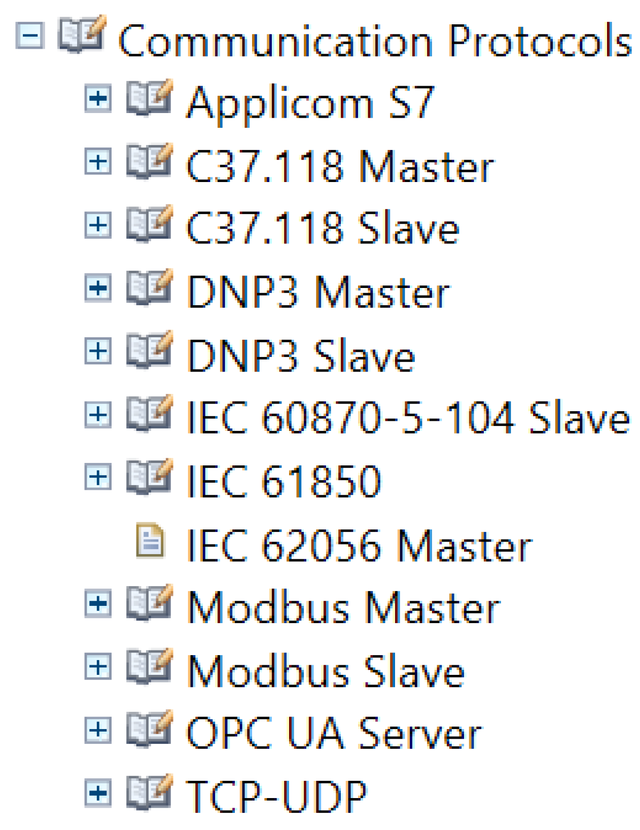
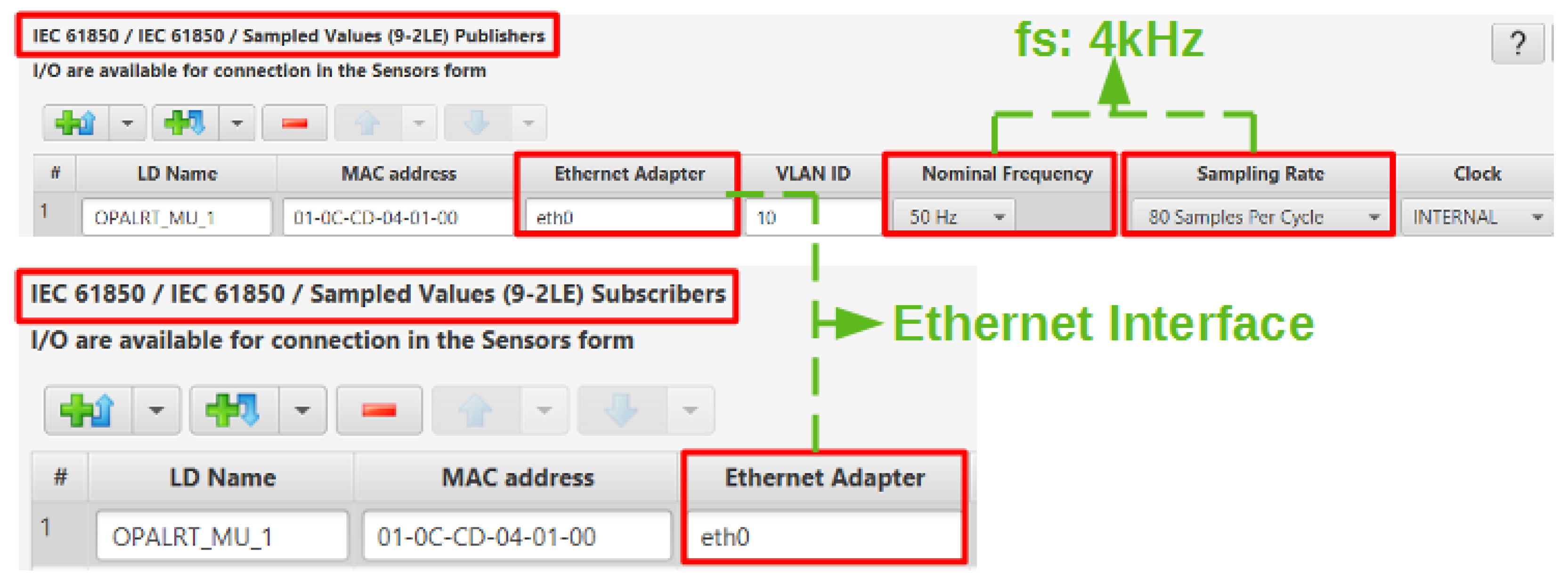
- Protocols: The popularity of the IEC 61850 protocol is attributed to its ease of connection via the Ethernet (rather than traditional hard wired systems and the standard structure of message offering interoperability). These features prove advantageous to attackers as Ethernet-based networks are easily accessible, and as it is a standard protocol, attackers can know its structure and hence its vulnerability. A similar argument also applies to other protocols such as Modbus and DNP3 [51]. To cope up with attacks, various encryption algorithms are been used to produce variants of protocols. However, it should be noted that the computation time for these checks must adhere to the required time and must not impede upon performance. The control and protection systems require real-time signals to take decisions and any delay in this loop could result in losses as well as environmental disasters. An example can be seen in the smart grid concept where the communication infrastructure has eminent significance, especially when matching energy generation and consumption schemes. If energy demand and response balance is not met, the stability of the grid may be compromised and lead to brown- and blackouts. Therefore, decisions for controlling various resources can have a drastic impact on the overall system behavior [52,53,54].
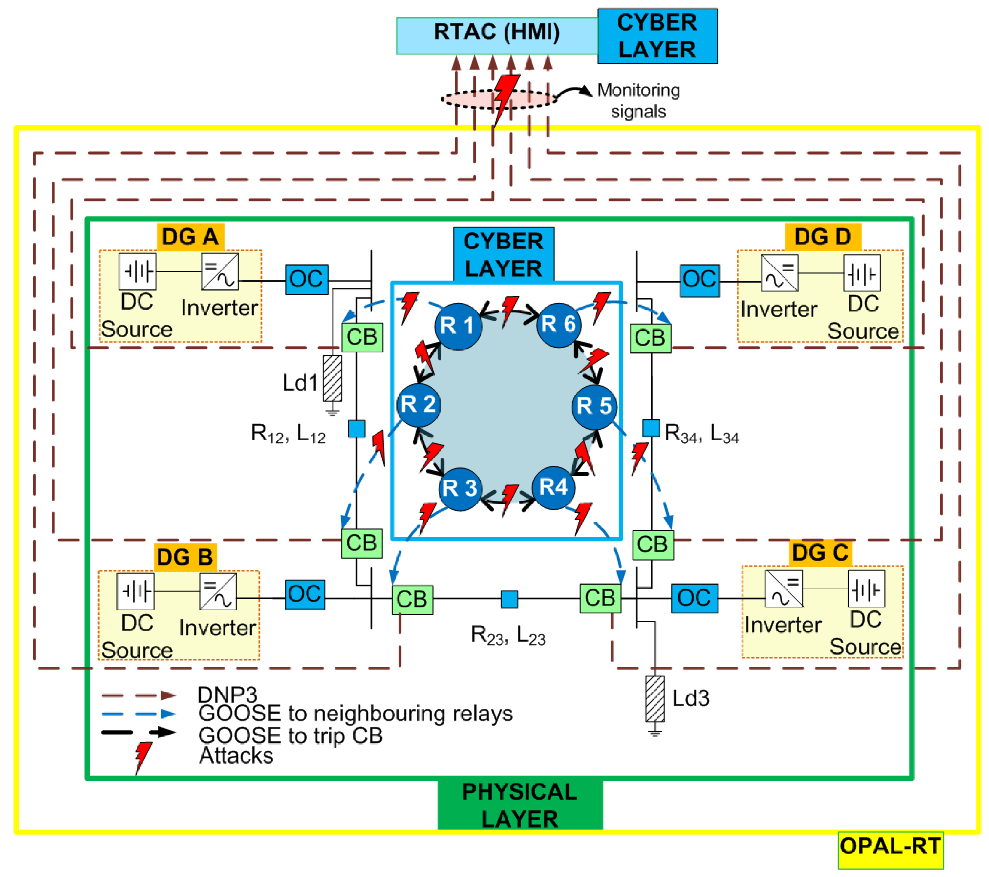
- PHYSICAL VULNERABILITIES: The devices in the physical layer may include sensors, relays, circuit breakers, primary controllers and secondary controllers. Primary controllers realized on digital signal processors (DSPs) are operated locally and they are thus not vulnerable to cyber attacks, as typically they do not have network access, but may be damaged physically [40]. Similarly, infiltration in the hardware supply chain can degrade and damage the equipment and devices.
3. Results on the Testbed
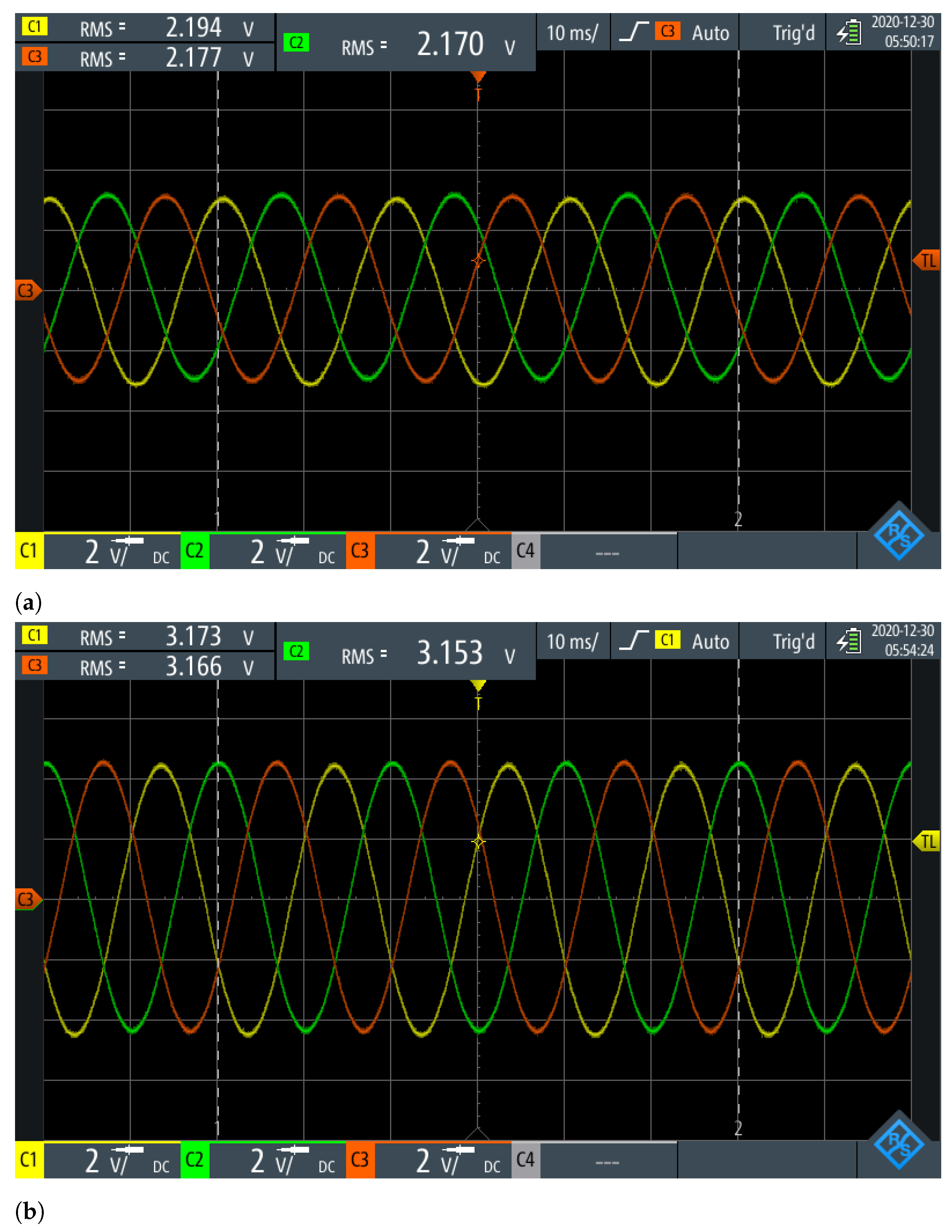
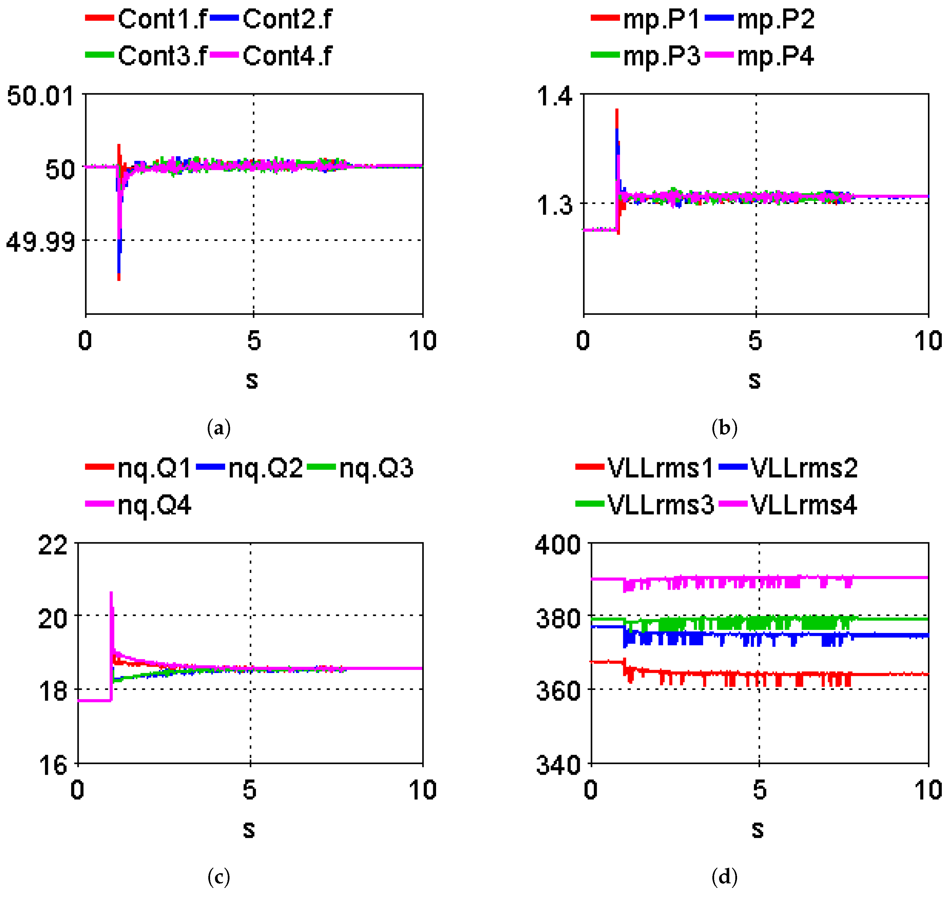
3.1. Real-Time Simulation Results
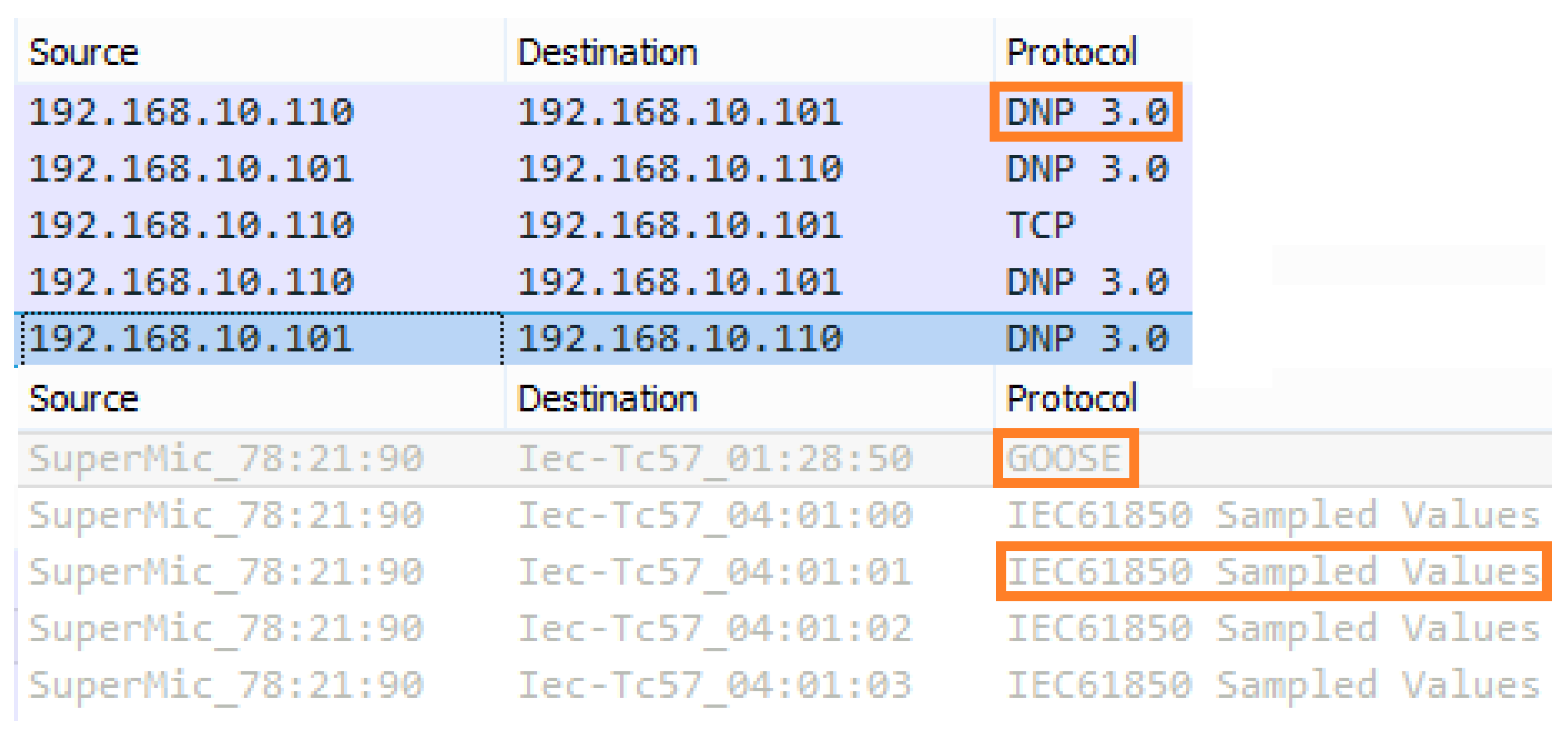
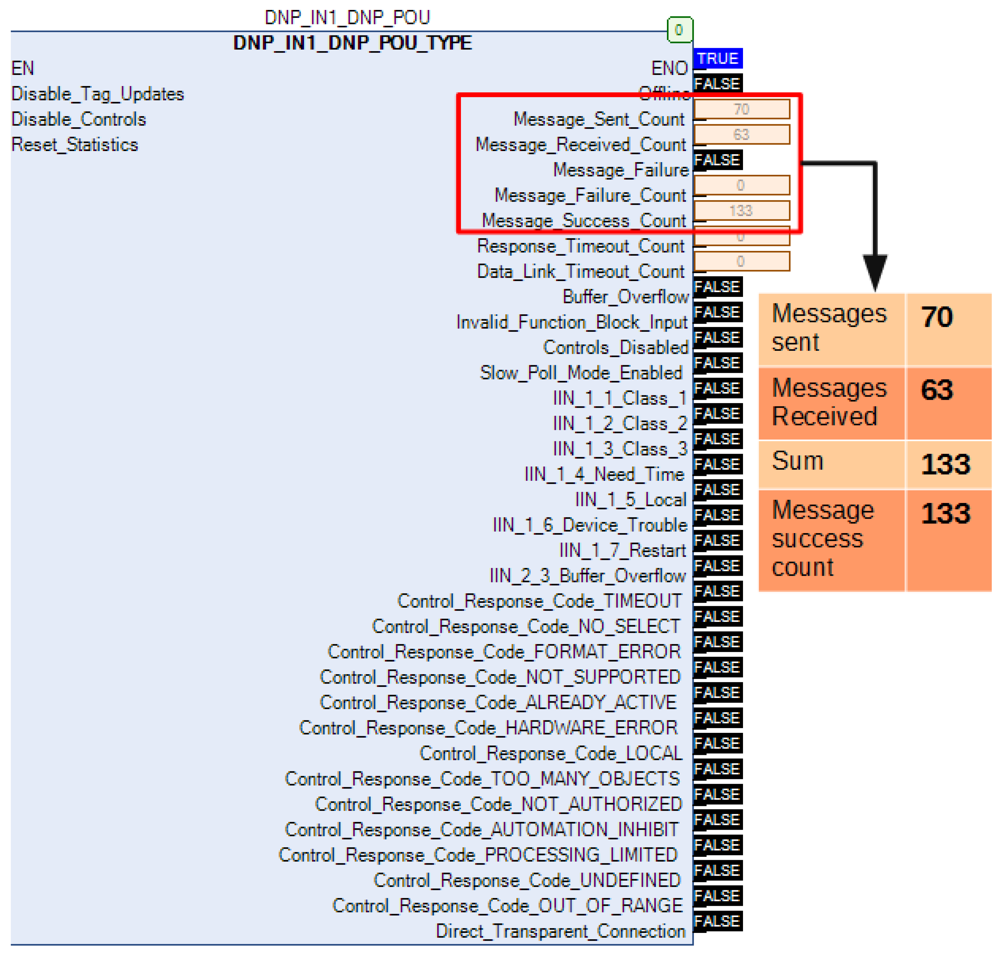
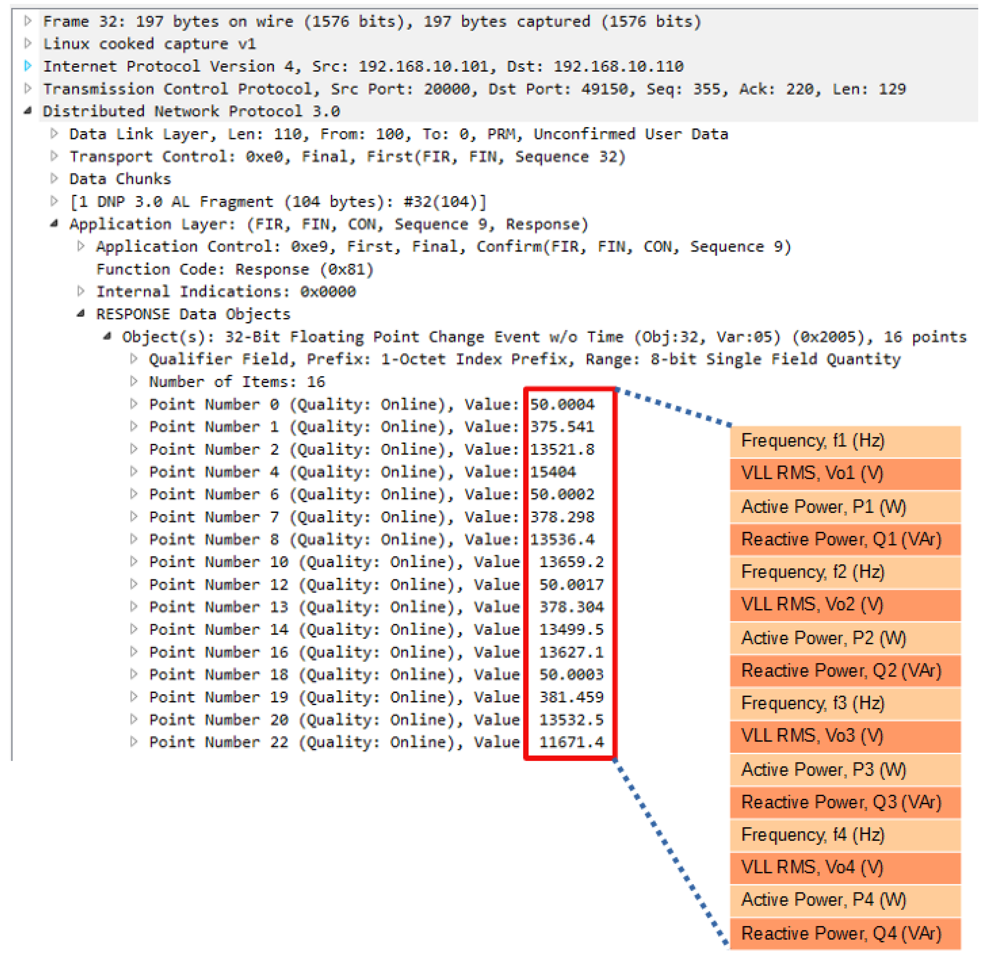
3.2. Communication Protocols Established
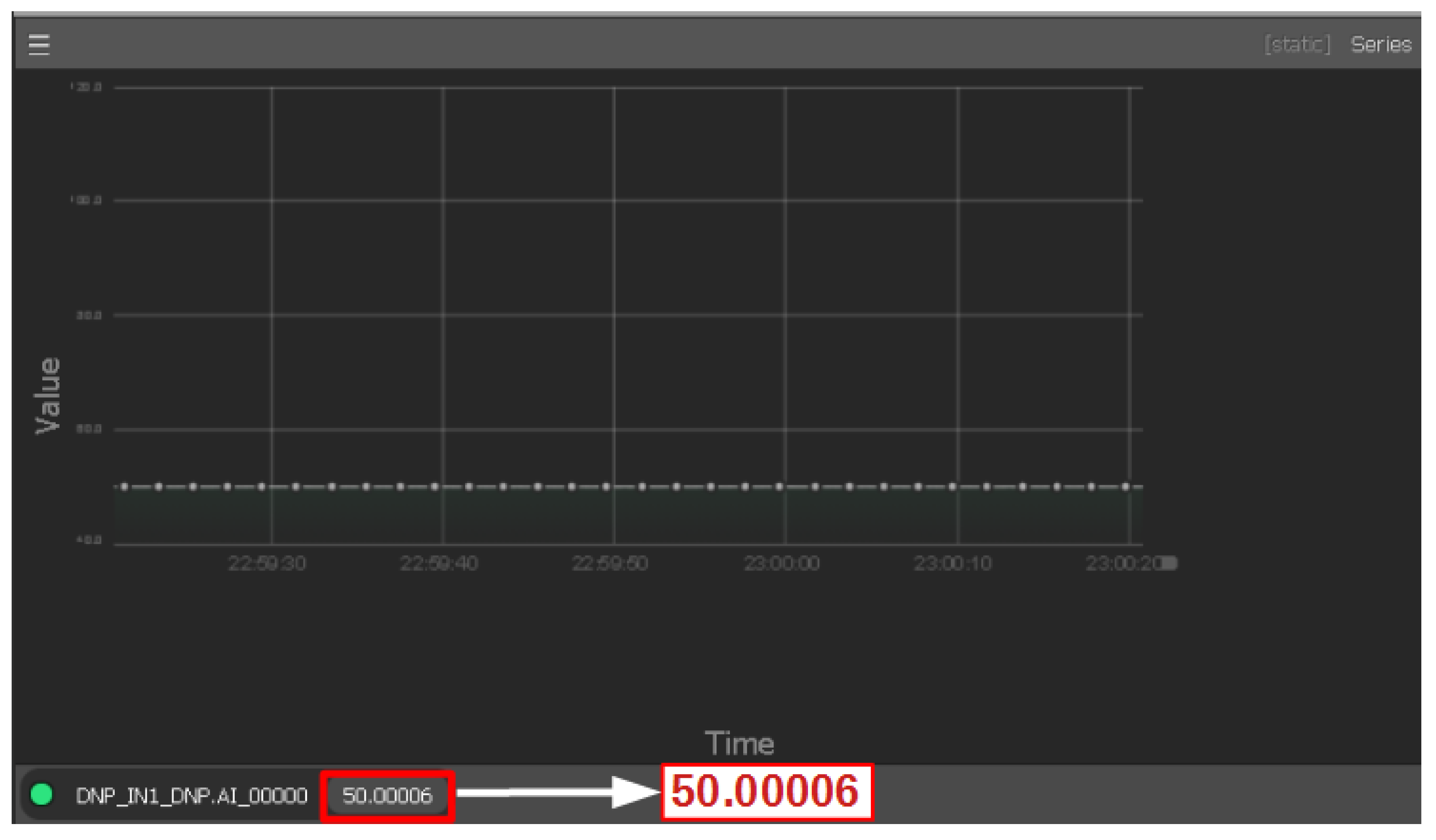
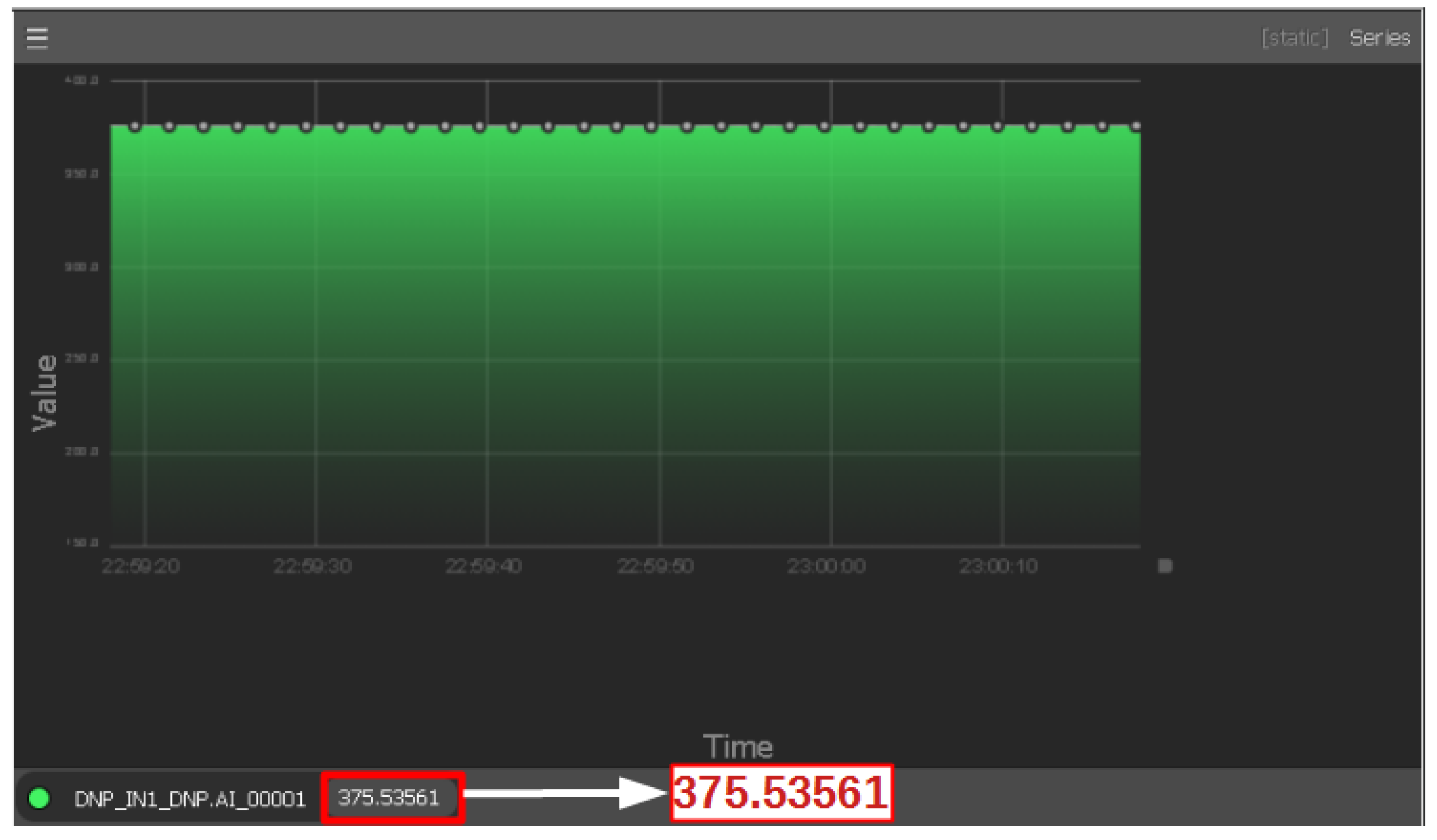
3.3. HMI
3.4. Attack Scenarios
4. Features of Testbed
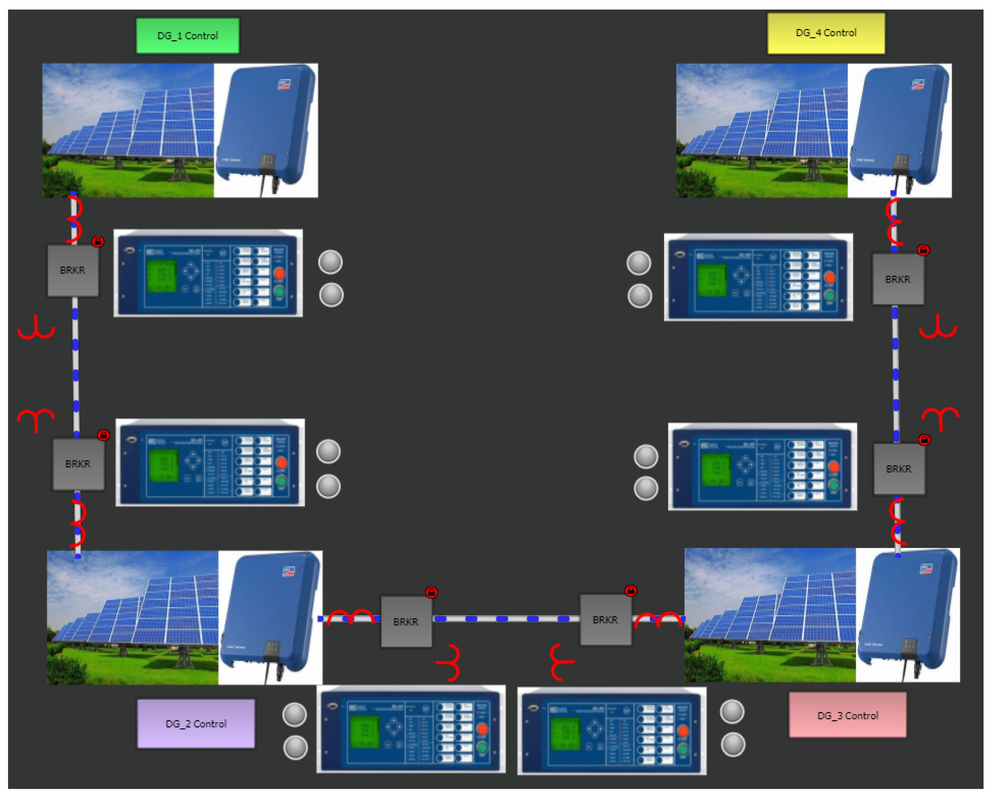
4.1. Scalability
4.2. Communication Protocol Variants
4.3. Attack Modeling
4.4. Extension to More Realistic Scenarios
4.5. Assessment Platform
5. Conclusions
Author Contributions
Funding
Conflicts of Interest
Abbreviations
| AMQP | Advanced Message Queuing Protocol |
| CAN | Controller Area Network |
| CA Rule 21 | California Rule 21 |
| CBs | Circuit Breakers |
| C-HIL | Controller Hardware in Loop |
| CL | Communication Link |
| CPS | Cyber-Physical System |
| CSIP | Common Smart Inverter Profile |
| CT | Current Transformer |
| DDS | Data Distribution Service |
| DERs | Distributed Energy Resources |
| DGs | Distributed Generations |
| DNP3 | Distributed Network Protocol |
| DoS | Denial of Service |
| DSC | Distributed Secondary Control |
| DSO | Digital Storage Oscilloscope |
| DSP | Digital Signal Processor |
| EmSec | Emission Security |
| FDIA | False Data Injection Attack |
| FIPAs | Foundation for Intelligent Physical Agents |
| GOOSE | Generic Object-Oriented Substation Event |
| GPS | Global Positioning System |
| GSE | Generic Stream Encapsulation |
| GUI | Graphical User Interface |
| HAR | Hit and Run |
| HMI | Human–Machine Interface |
| ICS | Industrial Control System |
| ICT | Information and Communication Technology |
| IEC | International Electrotechnical Commission |
| IEEE | Institute of Electrical and Electronics Engineers |
| IEDs | Intelligent Electronic Devices |
| I/O | Input/Output |
| IT | Information Technology |
| LAN | Local Area Network |
| LCs | Local Controllers |
| MC | Master Controller |
| MGs | Microgrids |
| MQTT | Message Queuing Telemetry Transport |
| MUs | Merging Units |
| NIST | National Institute of Standards and Technology |
| NISTIR | National Institute of Standards and Technology Internal Reports |
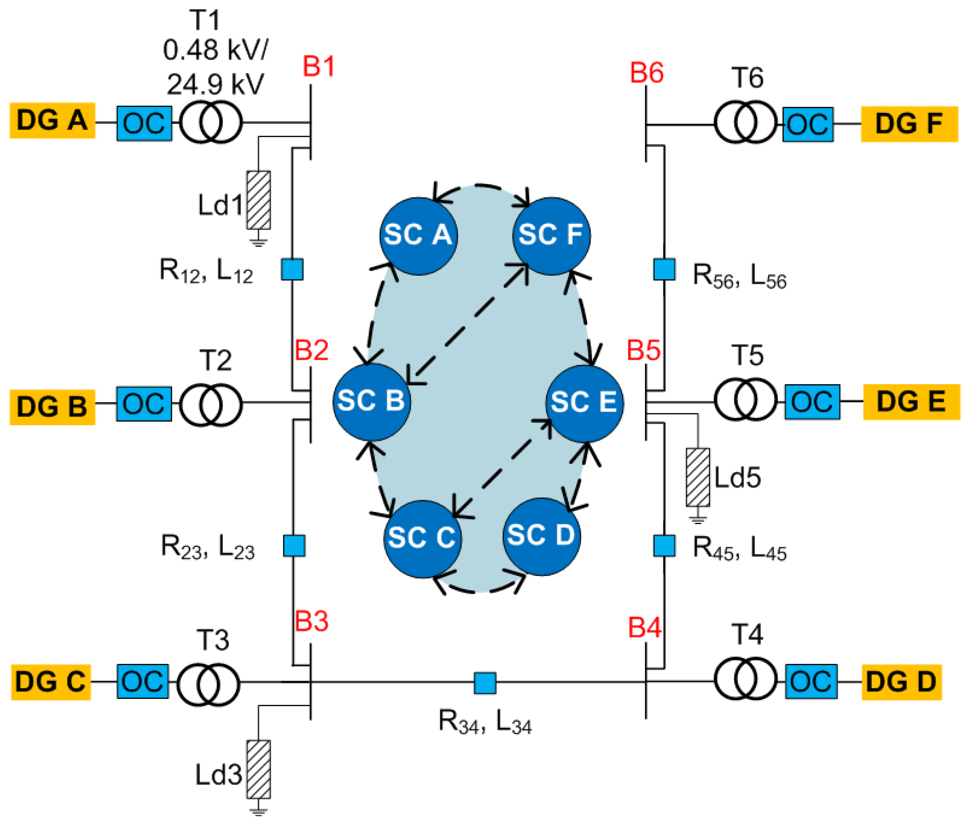
| OC | Output Connector |
| OPC UA | Open Platform Communications United Architecture Unified Architecture |
| PA | Persistent Attacks |
| PC | Primary Controller |
| P-HIL | Power Hardware In Loop |
| PI | Proportional Integral |
| PLC | Programmable Logic Controllers |
| PMA | Packet Mistreating Attacks |
| PMUs | Phasor Measurement Units |
| PT | Potential Transformer |
| RT | Real Time |
| RTAC | Real-Time Automation Controller |
| RTP | Routing Table Poisoning |
| RTU | Remote Terminal Unit |
| SC | Secondary Controller |
| SCADA | Supervisory Control and Data Acquisition |
| SIWG | Smart Inverter Working Group |
| SMV | Sampled Measured Values |
| SV | Sampled Value |
| VPN | Virtual Private Network |
| WAMS | Wide-Area Monitoring System |
| WAN | Wide-Area Network |
References
- Simard, G. Smart Grid Research: Power-IEEE Grid Vision 2050; IEEE: Piscataway, NJ, USA, 2013. [Google Scholar] [CrossRef]
- Faheem, M.; Shah, S.B.H.; Butt, R.A.; Raza, B.; Anwar, M.; Ashraf, M.W.; Ngadi, M.A.; Gungor, V.C. Smart grid communication and information technologies in the perspective of Industry 4.0: Opportunities and challenges. Comput. Sci. Rev. 2018, 30, 1–30. [Google Scholar] [CrossRef]
- Duan, J.; Wang, C.; Xu, H.; Liu, W.; Xue, Y.; Peng, J.-C.; Jiang, H. Distributed control of inverter-interfaced microgrids based on consensus algorithm with improved transient performance. IEEE Trans. Smart Grid 2017, 10, 1303–1312. [Google Scholar] [CrossRef]
- Sorebo, G.N.; Echols, M.C. Smart Grid Security: An End-to-End View of Security in the New Electrical Grid. Available online: https://www.routledge.com/Smart-Grid-Security-An-End-to-End-View-of-Security-in-the-New-Electrical/Sorebo-Echols/p/book/9781439855874 (accessed on 11 August 2021).
- Teixeira, A.; Amin, S.; Sandberg, H.; Johansson, K.H.; Sastry, S.S. Cyber security analysis of state estimators in electric power systems. In Proceedings of the 49th IEEE Conference on Decision and Control (CDC), Atlanta, GA, USA, 15–17 December 2010; pp. 5991–5998. [Google Scholar]
- Kosut, O.; Jia, L.; Thomas, R.J.; Tong, L. Malicious data attacks on the smart grid. IEEE Trans. Smart Grid 2011, 2, 645–658. [Google Scholar] [CrossRef] [Green Version]
- Loukas, G. Cyber-Physical Attacks: A gRowing Invisible Threat. Available online: https://www.elsevier.com/books/cyber-physical-attacks/loukas/978-0-12-801290-1 (accessed on 11 August 2021).
- Liu, C.-C.; Stefanov, A.; Hong, J.; Panciatici, P. Intruders in the grid. IEEE Power Energy Mag. 2011, 10, 58–66. [Google Scholar] [CrossRef]
- Reed, T.C. At the Abyss: An Insider’s History of the Cold War. Available online: https://lightsailed.com/catalog/book/at-the-abyss-an-insiders-history-of-the-cold-war-thomas-reed/9780307414625/ (accessed on 11 August 2021).
- Stuxnet. June 2015. Available online: https://en.wikipedia.org/wiki/Stuxnet (accessed on 11 August 2021).
- Case, D.U. Analysis of the Cyber Attack on the Ukrainian Power Grid; Electricity Information Sharing and Analysis Center (E-ISAC): Washington, DC, USA, 2016; Volume 388. [Google Scholar]
- Condliffe, J. Ukraine’s Power Grid Gets Hacked Again, a Worrying Sign for iNfrastructure Attacks. MIT Technology Review. 2016. Available online: https://www.technologyreview.com/2016/12/22/5969/ukraines-power-grid-gets-hacked-again-a-worrying-sign-for-infrastructure-attacks/ (accessed on 11 August 2021).
- Introduction to NISTIR 7628 Guidelines for Smart GRID Cyber Security. Available online: https://www.nist.gov/system/files/documents/smartgrid/nistir-7628_total-2.pdf (accessed on 11 August 2021).
- El Shafie, A.; Niyato, D.; Hamila, R.; Al-Dhahir, N. Impact of the wireless network’s PHY security and reliability on demand-side management cost in the smart grid. IEEE Access 2017, 5, 5678–5689. [Google Scholar] [CrossRef]
- Venkataramanan, V.; Hahn, A.; Srivastava, A. CP-SAM: Cyber-physical security assessment metric for monitoring microgrid resiliency. IEEE Trans. Smart Grid 2019, 11, 1055–1065. [Google Scholar] [CrossRef]
- Mazumder, S.K.; Kulkarni, A.; Sahoo, S.; Blaabjerg, F.; Mantooth, A.; Balda, J.; Zhao, Y.; Ramos-Ruiz, J.; Enjeti, P.; Kumar, P.R.; et al. A review of current research trends in power-electronic innovations in cyber-physical systems. IEEE J. Emerg. Sel. Top. Power Electron. 2021. [Google Scholar] [CrossRef]
- He, D.; Chan, S.; Zhang, Y.; Wu, C.; Wang, B. How effective are the prevailing attack-defense models for cybersecurity anyway? IEEE Intell. Syst. 2013, 29, 14–21. [Google Scholar] [CrossRef]
- Liu, R.; Vellaithurai, C.; Biswas, S.S.; Gamage, T.T.; Srivastava, A.K. Analyzing the cyber-physical impact of cyber events on the power grid. IEEE Trans. Smart Grid 2015, 6, 2444–2453. [Google Scholar] [CrossRef]
- Nelson, A.; Chakraborty, S.; Wang, D.; Singh, P.; Cui, Q.; Yang, L.; Suryanarayanan, S. Cyber-physical test platform for microgrids: Combining hardware, hardware-in-the-loop, and network-simulator-in-the-loop. In Proceedings of the 2016 IEEE Power and Energy Society General Meeting (PESGM), Boston, MA, USA, 17–21 July 2016; pp. 1–5. [Google Scholar]
- Cintuglu, M.H.; Mohammed, O.A. Cloud communication for remote access smart grid testbeds. In Proceedings of the 2016 IEEE Power and Energy Society General Meeting (PESGM), Boston, MA, USA, 17–21 July 2016; pp. 1–5. [Google Scholar]
- Zhang, H.; Ge, D.; Liu, J.; Zhang, Y. Multifunctional cyber-physical system testbed based on a source-grid combined scheduling control simulation system. IET Gener. Transm. Distrib. 2017, 11, 3144–3151. [Google Scholar] [CrossRef]
- Poudel, S.; Ni, Z.; Malla, N. Real-time cyber physical system testbed for power system security and control. Int. J. Electr. Power Energy Syst. 2017, 90, 124–133. [Google Scholar] [CrossRef]
- Hahn, A.; Ashok, A.; Sridhar, S.; Govindarasu, M. Cyber-physical security testbeds: Architecture, application, and evaluation for smart grid. IEEE Trans. Smart Grid 2013, 4, 847–855. [Google Scholar] [CrossRef]
- Stanovich, M.J.; Leonard, I.; Sanjeev, K.; Steurer, M.; Roth, T.P.; Jackson, S.; Bruce, M. Development of a smart-grid cyber-physical systems testbed. In Proceedings of the 2013 IEEE PES Innovative Smart Grid Technologies Conference (ISGT), Washington, DC, USA, 24–27 February 2013; pp. 1–6. [Google Scholar]
- Wei, M.; Wang, W. Greenbench: A benchmark for observing power grid vulnerability under data-centric threats. In Proceedings of the IEEE INFOCOM 2014-IEEE Conference on Computer Communications, Toronto, ON, Canada, 27 April–2 May 2014; pp. 2625–2633. [Google Scholar]
- Cintuglu, M.H.; Youssef, T.; Mohammed, O.A. Development and application of a real-time testbed for multiagent system interoperability: A case study on hierarchical microgrid control. IEEE Trans. Smart Grid 2016, 9, 1759–1768. [Google Scholar] [CrossRef]
- Hammad, E.; Ezeme, M.; Farraj, A. Implementation and development of an offline co-simulation testbed for studies of power systems cyber security and control verification. Int. J. Electr. Power Energy Syst. 2019, 104, 817–826. [Google Scholar] [CrossRef]
- Duan, N.; Yee, N.; Salazar, B.; Joo, J.-Y.; Stewart, E.; Cortez, E. Cybersecurity analysis of distribution grid operation with distributed energy resources via co-simulation. In Proceedings of the 2020 IEEE Power & Energy Society General Meeting (PESGM), Montreal, QC, Canada, 2–6 August 2020; pp. 1–5. [Google Scholar]
- Wang, Z.; Qi, D.; Mei, J.; Li, Z.; Wan, K.; Zhang, J. Real-time controller hardware-in-the-loop co-simulation testbed for cooperative control strategy for cyber-physical power system. Glob. Energy Interconnect. 2021, 4, 214–224. [Google Scholar] [CrossRef]
- Musleh, A.S.; Chen, G.; Dong, Z.Y. A survey on the detection algorithms for false data injection attacks in smart grids. IEEE Trans. Smart Grid 2019, 11, 2218–2234. [Google Scholar] [CrossRef]
- Chawla, A.; Agrawal, P.; Singh, A.; Panigrahi, B.K.; Paul, K.; Bhalja, B. Denial-of-service resilient frameworks for synchrophasor-based wide area monitoring systems. Computer 2020, 53, 14–24. [Google Scholar] [CrossRef]
- Khodaei, A. Microgrid optimal scheduling with multi-period islanding constraints. IEEE Trans. Power Syst. 2013, 29, 1383–1392. [Google Scholar] [CrossRef]
- Bidram, A.; Davoudi, A. Hierarchical structure of microgrids control system. IEEE Trans. Smart Grid 2012, 3, 1963–1976. [Google Scholar] [CrossRef]
- Bidram, A.; Davoudi, A.; Lewis, F.L.; Qu, Z. Secondary control of microgrids based on distributed cooperative control of multi-agent systems. IET Gener. Transm. Distrib. 2013, 7, 822–831. [Google Scholar] [CrossRef] [Green Version]
- Simpson-Porco, J.W.; Shafiee, Q.; Dörfler, F.; Vasquez, J.C.; Guerrero, J.M.; Bullo, F. Secondary frequency and voltage control of islanded microgrids via distributed averaging. IEEE Trans. Ind. Electron. 2015, 62, 7025–7038. [Google Scholar] [CrossRef]
- Burbano, R.A.G.; Gutierrez, M.L.O.; Restrepo, J.A.; Guerrero, F.G. IED Design for a Small-Scale Microgrid Using IEC 61850. IEEE Trans. Ind. Appl. 2019, 55, 7113–7121. [Google Scholar] [CrossRef]
- Du, Y.; Tu, H.; Lukic, S. Distributed control strategy to achieve synchronized operation of an islanded MG. IEEE Trans. Smart Grid 2018, 10, 4487–4496. [Google Scholar] [CrossRef]
- Commission, C.E.; Commission, C.P.U. Recommendations for Utility Communications with Distributed Energy Resources (DER) Systems with Smart Inverters; SIWG Phase 2: Sacramento, CA, USA, 2015. [Google Scholar]
- Obert, J.; Cordeiro, P.; Johnson, J.; Lum, G.; Tansy, T.; Pala, M.; Ih, R. Recommendations for Trust and Encryption in der Interoperability Standards; Technical Report; SAND2019–1490; Sandia National Laboratories: Albuquerque, NM, USA, 2019. [Google Scholar]
- Wang, Y.; Mondal, S.; Deng, C.; Satpathi, K.; Xu, Y.; Dasgupta, S. Cyber-Resilient Cooperative Control of Bidirectional Interlinking Converters in Networked AC/DC Microgrids. IEEE Trans. Ind. Electron. 2020, 68, 9707–9718. [Google Scholar] [CrossRef]
- Rath, S.; Pal, D.; Sharma, P.S.; Panigrahi, B.K. A Cyber-Secure Distributed Control Architecture for Autonomous AC Microgrid. IEEE Syst. J. 2020, 1–12. [Google Scholar] [CrossRef]
- Starke, M.; Herron, A.; King, D.; Xue, Y. Implementation of a publish-subscribe protocol in microgrid islanding and resynchronization with self-discovery. IEEE Trans. Smart Grid 2017, 10, 361–370. [Google Scholar] [CrossRef]
- Mohanty, R.; Sahoo, S.; Pradhan, A.K.; Blaabjerg, F. A Cosine Similarity Based Centralized Protection Scheme for DC Microgrids. IEEE J. Emerg. Sel. Top. Power Electron. 2021. [Google Scholar] [CrossRef]
- Habib, H.F.; Youssef, T.; Cintuglu, M.H.; Mohammed, O. A multi-agent based technique for fault location, isolation and service restoration. In Proceedings of the 2016 IEEE Industry Applications Society Annual Meeting, Portland, OR, USA, 2–6 October 2016; pp. 1–8. [Google Scholar]
- Cintuglu, M.H.; Ma, T.; Mohammed, O.A. Protection of autonomous microgrids using agent-based distributed communication. IEEE Trans. Power Deliv. 2016, 32, 351–360. [Google Scholar] [CrossRef]
- Rahman, M.S.; Mahmud, M.A.; Oo, A.M.T.; Pota, H.R. Multi-agent approach for enhancing security of protection schemes in cyber-physical energy systems. IEEE Trans. Ind. Inform. 2016, 13, 436–447. [Google Scholar] [CrossRef]
- Kimura, S.; Rotta, A.; Abboud, R.; Moraes, R.; Zanirato, E.; Bahia, J. Applying IEC 61850 to real life: Modernization project for 30 electrical substations. In Proceedings of the 10th Annual Western Power Delivery Automation Conference, Spokane, WA, USA, 21–23 April 2008. [Google Scholar]
- Habib, H.F.; Mohamed, A.; El Hariri, M.; Mohammed, O.A. Utilizing supercapacitors for resiliency enhancements and adaptive microgrid protection against communication failures. Electr. Power Syst. Res. 2017, 145, 223–233. [Google Scholar] [CrossRef] [Green Version]
- Sahoo, S.; Dragičević, T.; Blaabjerg, F. Cyber Security in Control of Grid-Tied Power Electronic Converters–Challenges and Vulnerabilities. IEEE J. Emerg. Sel. Top. Power Electron. 2019. [Google Scholar] [CrossRef]
- Bidram, A.; Poudel, B.; Damodaran, L.; Fierro, R.; Guerrero, J.M. Resilient and cybersecure distributed control of inverter-based islanded microgrids. IEEE Trans. Ind. Inform. 2019, 16, 3881–3894. [Google Scholar] [CrossRef]
- Hussain, S.S.; Ustun, T.S.; Kalam, A. A review of IEC 62351 security mechanisms for IEC 61850 message exchanges. IEEE Trans. Ind. Inform. 2019, 16, 5643–5654. [Google Scholar] [CrossRef]
- Volkova, A.; Niedermeier, M.; Basmadjian, R.; de Meer, H. Security challenges in control network protocols: A survey. IEEE Commun. Surv. Tutor. 2018, 21, 619–639. [Google Scholar] [CrossRef]
- Hussain, S.S.; Farooq, S.M.; Ustun, T.S. A method for achieving confidentiality and integrity in IEC 61850 GOOSE messages. IEEE Trans. Power Deliv. 2020, 35, 2565–2567. [Google Scholar] [CrossRef]
- Hoyos, J.; Dehus, M.; Brown, T.X. Exploiting the GOOSE protocol: A practical attack on cyber-infrastructure. In Proceedings of the 2012 IEEE Globecom Workshops, Anaheim, CA, USA, 3–7 December 2012; pp. 1508–1513. [Google Scholar]
- Sánchez, H.S.; Rotondo, D.; Escobet, T.; Puig, V.; Quevedo, J. Bibliographical review on cyber attacks from a control oriented perspective. Annu. Rev. Control 2019, 48, 103–128. [Google Scholar] [CrossRef] [Green Version]
- Zhang, H.; Qi, Y.; Wu, J.; Fu, L.; He, L. DoS attack energy management against remote state estimation. IEEE Trans. Control. Netw. Syst. 2016, 5, 383–394. [Google Scholar] [CrossRef]
- Chlela, M.; Mascarella, D.; Joos, G.; Kassouf, M. Fallback control for isochronous energy storage systems in autonomous microgrids under denial-of-service cyber-attacks. IEEE Trans. Smart Grid 2017, 9, 4702–4711. [Google Scholar] [CrossRef]
- Understanding Denial-of-Service Attacks | US-CERT. 6 February 2013. Available online: https://www.us-cert.gov/ncas/tips/ST04-015 (accessed on 8 March 2017).
- Liang, G.; Zhao, J.; Luo, F.; Weller, S.R.; Dong, Z.Y. A review of false data injection attacks against modern power systems. IEEE Trans. Smart Grid 2016, 8, 1630–1638. [Google Scholar] [CrossRef]
- Liu, X.; Li, Z. False data attacks against AC state estimation with incomplete network information. IEEE Trans. Smart Grid 2016, 8, 2239–2248. [Google Scholar] [CrossRef]
- Saha, S.; Roy, T.; Mahmud, M.; Haque, M.; Islam, S. Sensor fault and cyber attack resilient operation of DC microgrids. Int. J. Electr. Power Energy Syst. 2018, 99, 540–554. [Google Scholar] [CrossRef]
- Chlela, M.; Joos, G.; Kassouf, M.; Brissette, Y. Real-time testing platform for microgrid controllers against false data injection cybersecurity attacks. In Proceedings of the 2016 IEEE Power and Energy Society General Meeting (PESGM), Boston, MA, USA, 17–21 July 2016; pp. 1–5. [Google Scholar]
- Zhang, H.; Meng, W.; Qi, J.; Wang, X.; Zheng, W.X. Distributed load sharing under false data injection attack in an inverter-based microgrid. IEEE Trans. Ind. Electron. 2018, 66, 1543–1551. [Google Scholar] [CrossRef]
- Torre, G.D.L.; Yucelen, T. Adaptive architectures for resilient control of networked multiagent systems in the presence of misbehaving agents. Int. J. Control 2018, 91, 495–507. [Google Scholar] [CrossRef]
- Sahoo, S.; Peng, J.C.-H.; Mishra, S.; Dragičević, T. Distributed screening of hijacking attacks in DC microgrids. IEEE Trans. Power Electron. 2019, 35, 7574–7582. [Google Scholar] [CrossRef]
- Rekik, M.; Chtourou, Z.; Gransart, C.; Atieh, A. A cyber-physical threat analysis for microgrids. In Proceedings of the 2018 15th International Multi-Conference on Systems, Signals & Devices (SSD), Yasmine Hammamet, Tunisia, 19–22 March 2018; pp. 731–737. [Google Scholar]
- Akella, R.; Tang, H.; McMillin, B.M. Analysis of information flow security in cyber—Physical systems. Int. J. Crit. Infrastruct. Prot. 2010, 3, 157–173. [Google Scholar] [CrossRef]
- Dibaji, S.M.; Pirani, M.; Flamholz, D.B.; Annaswamy, A.M.; Johansson, K.H.; Chakrabortty, A. A systems and control perspective of CPS security. Annu. Rev. Control 2019, 47, 394–411. [Google Scholar] [CrossRef] [Green Version]
- Brugman, J.; Khan, M.; Kasera, S.; Parvania, M. Cloud based intrusion detection and prevention system for industrial control systems using software defined networking. In Proceedings of the 2019 Resilience Week (RWS), San Antonio, TX, USA, 4–7 November 2019; pp. 98–104. [Google Scholar]
- Sahoo, S.; Dragičević, T.; Blaabjerg, F. An event-driven resilient control strategy for dc microgrids. IEEE Trans. Power Electron. 2020, 35, 13714–13724. [Google Scholar] [CrossRef]
- Sahoo, S.; Peng, J.C.-H. A localized event-driven resilient mechanism for cooperative microgrid against data integrity attacks. IEEE Trans. Cybern. 2020, 51, 3687–3698. [Google Scholar] [CrossRef]
- Sahoo, S.; Dragičević, T.; Blaabjerg, F. Resilient operation of heterogeneous sources in cooperative DC microgrids. IEEE Trans. Power Electron. 2020, 35, 12601–12605. [Google Scholar] [CrossRef]
- Sahoo, S.; Dragičević, T.; Blaabjerg, F. Multilayer Resilience Paradigm Against Cyber Attacks in DC Microgrids. IEEE Trans. Power Electron. 2020, 36, 2522–2532. [Google Scholar] [CrossRef]
- Danzi, P.; Angjelichinoski, M.; Stefanović, Č.; Dragičević, T.; Popovski, P. Software-defined microgrid control for resilience against denial-of-service attacks. IEEE Trans. Smart Grid 2018, 10, 5258–5268. [Google Scholar] [CrossRef]
- Danzi, P.; Angjelichinoski, M.; Stefanović, Č.; Popovski, P. Anti-jamming strategy for distributed microgrid control based on power talk communication. In Proceedings of the 2017 IEEE International Conference on Communications Workshops (ICC Workshops), Paris, France, 21–25 May 2017; pp. 911–917. [Google Scholar]
- Lu, Z.; Wang, W.; Wang, C. Camouflage traffic: Minimizing message delay for smart grid applications under jamming. IEEE Trans. Dependable Secur. Comput. 2014, 12, 31–44. [Google Scholar] [CrossRef] [Green Version]
- Manandhar, K.; Cao, X.; Hu, F.; Liu, Y. Detection of faults and attacks including false data injection attack in smart grid using Kalman filter. IEEE Trans. Control. Netw. Syst. 2014, 1, 370–379. [Google Scholar] [CrossRef]
- Zhao, J.; Zhang, G.; La Scala, M.; Dong, Z.Y.; Chen, C.; Wang, J. Short-term state forecasting-aided method for detection of smart grid general false data injection attacks. IEEE Trans. Smart Grid 2015, 8, 1580–1590. [Google Scholar] [CrossRef]
- Sahoo, S.; Mishra, S.; Peng, J.C.-H.; Dragičević, T. A stealth cyber-attack detection strategy for DC microgrids. IEEE Trans. Power Electron. 2018, 34, 8162–8174. [Google Scholar] [CrossRef] [Green Version]
- Sahoo, S.; Peng, J.C.-H.; Devakumar, A.; Mishra, S.; Dragičević, T. On detection of false data in cooperative dc microgrids—A discordant element approach. IEEE Trans. Ind. Electron. 2019, 67, 6562–6571. [Google Scholar] [CrossRef]
- Cecilia, A.; Sahoo, S.; Dragičević, T.; Costa-Castelló, R.; Blaabjerg, F. Detection and Mitigation of False Data in Cooperative DC Microgrids With Unknown Constant Power Loads. IEEE Trans. Power Electron. 2021, 36, 9565–9577. [Google Scholar] [CrossRef]
- Zhang, J.; Sahoo, S.; Peng, J.C.-H.; Blaabjerg, F. Mitigating Concurrent False Data Injection Attacks in Cooperative DC Microgrids. IEEE Trans. Power Electron. 2021, 36, 9637–9647. [Google Scholar] [CrossRef]
- Pillitteri, V.Y.; Brewer, T.L. Guidelines for Smart Grid Cybersecurity; NIST Interagency/Internal Report (NISTIR); National Institute of Standards and Technology: Gaithersburg, MD, USA, 2014. [CrossRef]
- Sahoo, S.; Yang, Y.; Blaabjerg, F. Resilient synchronization strategy for ac microgrids under cyber attacks. IEEE Trans. Power Electron. 2020, 36, 73–77. [Google Scholar] [CrossRef]
- Sadabadi, M.S.; Sahoo, S.; Blaabjerg, F. A Fully Resilient Cyber-Secure Synchronization Strategy for AC Microgrids. IEEE Trans. Power Electron. 2021. [Google Scholar] [CrossRef]

| Year: Testbed (Platform) | Targeted Objective | Distinctive Features | Communication Protocols | Tools |
|---|---|---|---|---|
| 2013: [23] PowerCyber Testbed (Real-Time (RT) Co-Simulation) | Wide-area situational awareness, cybersecurity | Impact on voltage stability | IEC 61850, C37.118, Modbus, DNP3, OPC UA | RTDS, DigSilent |
| 2013: [24] Florida State University (Controller Hardware in Loop) | Distribution grid management, demand response | Impact study on distributed control | TCP/IP | RTDS |
| 2014: [25] Greenbench (RT Co-Simulation) | Cybersecurity | Impact study on power system dynamics | TCP/UDP | PSCAD, OMNeT++ |
| 2015: [18] Physical Co-Simulation Testbed (RT Co-Simulation) | Cybersecurity | Impact on wide-area voltage stability control | C37.118-2005, C37.118-2011 | RTDS, RSCAD, DeterLab, NS-3 |
| 2016: [19] Microgrids Testbed (RT Co-Simulation) | System performance | Impact study on controllers | Modbus | Simulink, OPAL-RT, OMNeT++ |
| 2016: [20] Communication-Based Remote Access Testbed (Hardware) | Remote control, cybersecurity, wide-area situational awareness | Cloud communication for central controller with SCADA and relays | OPC UA, C37.118.1, C37.118.2, IEC 61850, Modbus | Skkynet, Kepware, ReLab |
| 2017: [21] Multifunctional CPS Testbed (RT Co-Simulation) | Cybersecurity | Impact study on multi-level control centres | DNP3.0, IEC 60870-5-104 | RTDS, WANE |
| 2017: [22] South Dakota State University (Hardware in Loop) | Cybersecurity and stability control of power system | Power system protection and control | DNP3.0, SEL-C662 | OPAL-RT, RT-lab |
| 2018: [26] (Real-Time Testbed) | Hierarchical microgrid control | Multi-agent control and protection | IEC61850, DDS | FIPAs, DDS Middleware |
| 2019: [27] (Offline Co-Simulation) | Power systems cybersecurity and control verification | Economical as offline | TCP/IP | EMTDC/PSCAD, OMNeT++, MATLAB |
| 2020: [28] (RT Co-Simulation) | Cybersecurity | Resource management study | IEEE 1815 | NS-3, QEMU, HELICS, Opendnp3, GridLAB-D |
| 2021: [29] (Controller Hardware in Loop Co-Simulation) | Cooperative control | Impact study on controllers with TCP/IP | TCP/IP | RT-LAB, OPNET |
| 2021: Testbed in this paper (RT Co-Simulation) | Cybersecurity, remote control, cooperative control and protection of microgrid | Impact study on standard protocols for cooperative control and protection with local/web-based HMI | SMV, GOOSE, Modbus, DNP3.0 | OPAL-RT, Hypersim, RTAC, ACSELERATOR RTAC SEL-5033 software, ACSELERATOR Diagram Builder SEL-503 |
| Active power droop coefficient | 9.4 × 10 | ||
| Reactive power droop coefficient | 1.3 × 10 | ||
| Voltage controller proportional gain | 0.2 | ||
| Voltage controller integral gain | 1 | ||
| Current controller proportional gain | 50 | ||
| Current controller integral gain | 100 | ||
| Line parameters | = 0.23 | = 318 H | |
| = 0.35 | = 1847 H | ||
| = 0.23 | = 318 H | ||
| Load parameters | () | = 36 kW | = 36 kVAr |
| () | = 45.9 kW | = 22.8 kVAr | |
| Gains | 40 | |
| 1.5 | ||
| Reference frequency | 2.50 |
| Types of Attacks | Objectives Fulfilled in Equations | Consequences | ||
|---|---|---|---|---|
| Frequency Restoration (1) | Proportional Active and Reactive Power Sharing (2), (3) | |||
| DoS | No | No | Prevents authorized access to data/service | |
| FDI | Individual node attack | No | No | Disrupts network stability and control |
| Coordinated node attack | ||||
| CASE: I | Yes | No | Alters original active power sharing to gain additional profits | |
| CASE: II | No | Yes | Deviates system frequency affecting stability | |
| CASE: III | Yes | Yes | Remains stealth initially, later disorients the system operation | |
| Hijacking | No | No | Deters optimal performance | |
| DoS + FDI | No | No | Affects both accessibility and optimal operation | |
| Type of Attack | Attack Location | Consequences |
|---|---|---|
| DoS | CL | Stops the data stream |
| Time delay | LC, MC, CL | Delays the data exchanges |
| FDI | LC, MC, CL | Manipulates the data |
| Testbed | Characteristic | Testbed Cost | Test Fidelity | Test Coverage | |
|---|---|---|---|---|---|
| Actual Devices | Simulated Devices | ||||
| Simulation | None | All | Low | Low | High |
| C-HIL | Controller | Rest | Moderate | Moderate (less) | High |
| P-HIL | Controller and one power equipment | Rest | High | Moderate (more) | Moderate |
| Power testbed | Scaled down DER equipment | None | High | Moderate (more) | Low |
| Full system | All | None | High | High | Low |
Publisher’s Note: MDPI stays neutral with regard to jurisdictional claims in published maps and institutional affiliations. |
© 2021 by the authors. Licensee MDPI, Basel, Switzerland. This article is an open access article distributed under the terms and conditions of the Creative Commons Attribution (CC BY) license (https://creativecommons.org/licenses/by/4.0/).
Share and Cite
Gupta, K.; Sahoo, S.; Panigrahi, B.K.; Blaabjerg, F.; Popovski, P. On the Assessment of Cyber Risks and Attack Surfaces in a Real-Time Co-Simulation Cybersecurity Testbed for Inverter-Based Microgrids. Energies 2021, 14, 4941. https://doi.org/10.3390/en14164941
Gupta K, Sahoo S, Panigrahi BK, Blaabjerg F, Popovski P. On the Assessment of Cyber Risks and Attack Surfaces in a Real-Time Co-Simulation Cybersecurity Testbed for Inverter-Based Microgrids. Energies. 2021; 14(16):4941. https://doi.org/10.3390/en14164941
Chicago/Turabian StyleGupta, Kirti, Subham Sahoo, Bijaya Ketan Panigrahi, Frede Blaabjerg, and Petar Popovski. 2021. "On the Assessment of Cyber Risks and Attack Surfaces in a Real-Time Co-Simulation Cybersecurity Testbed for Inverter-Based Microgrids" Energies 14, no. 16: 4941. https://doi.org/10.3390/en14164941
APA StyleGupta, K., Sahoo, S., Panigrahi, B. K., Blaabjerg, F., & Popovski, P. (2021). On the Assessment of Cyber Risks and Attack Surfaces in a Real-Time Co-Simulation Cybersecurity Testbed for Inverter-Based Microgrids. Energies, 14(16), 4941. https://doi.org/10.3390/en14164941