1. Introduction
Conventional power grids are highly centralised in power generation and usually have a unidirectional flow of power and energy from large synchronous generators and induction generators to end-users through a transmission network. However, the emergence of renewable distributed energy resource (DER) units (e.g., wind, photovoltaics, batteries, biomass, fuel cells and micro-turbines) has made it possible to curb the dependency on fossil fuel-based power generators and change the unidirectionality of energy flow in power grids [
1,
2,
3]. Such technologies have made it possible to achieve local power reliability and sustainable energy utilisation. With enough power generated by local DER units, certain localities can be disconnected from the primary power grid, forming a self-sustainable “microgrid” with an interconnected energy system within clearly defined electrical boundaries.
Although there is no clear definition of a microgrid (MG), the concept of microgrids was proposed by the Consortium for Electric Reliability Technology Solutions (CERTS) [
4], defining a microgrid as a localised entity that consists of DER units and controllable thermal and electrical loads. From the utility perspective, a microgrid can be treated as a single controllable node in the power system, whereas from the customer perspective, a microgrid can be seen as a source to provide reliable and continuous power [
5]. Based on the European Technology Platform of Smart Grids [
6], a microgrid can be seen as a platform that facilitates seamless integration of energy storage systems (ESS), DER units and thermal/electrical loads, ensuring that it can generate and supply sustainable, price-competitive and reliable electricity. The microgrid concept makes it possible to integrate small-scale DERs for providing local low-voltage power distribution. Microgrids have made it possible to supply highly reliable power within a locality, both residential and commercial. MGs are capable of operating in both grid-connected and stand-alone islanded modes, and also for handling a seamless transition from one mode to other. In grid-connected mode, with enough DER units, it can also provide extra revenue streams for the community by trading extra energy to the main grid. MGs also provide the security of being robust enough to provide energy in periods of severe weather and natural disasters by not having large transmission infrastructure above ground that needs regular maintenance.
Due to the fluctuating daily load demand profiles and intermittent nature of renewable energy resources, the power supply in MGs sometimes fails to meet power load demands, which leads to frequency fluctuations. An ESS allows electricity to be produced and stored at times of either low demand and low generation cost or from intermittent energy sources, and to be used at times of high demand, high generation cost or when no other generation means is available (
Figure 1). Therefore, ESSs and control infrastructure for energy management systems play an essential role in the power systems and MGs. This paper reviews and characterises important types of energy storage systems used in microgrids and different control strategies applied in MGs. Various challenges and issues related to ESSs and MGs control is also discussed.
2. Overview of Energy Storage Systems
Within technical limitations of thermodynamics, electrical energy can’t be stored on a large scale. It is more accessible and much more sustainable to store energy in other forms such as chemical, mechanical and thermal energy. In order to choose the right technology for a given application, energy storage systems can be classified based on power and energy density, life cycle of components used and charge/discharge rates. The effective efficiencies of all ESSs are also discussed in this chapter. The efficiency of an ESS is here defined as the round-trip DC-to-storage-to-DC energy efficiency of the storage bank, or the fraction of energy put into the storage that can be retrieved.
ESSs play an essential role in improving the operational capabilities of an MG. Although not all of them can be used successfully in MGs, there are many different types of ESS. The following section provides an overview to ESSs that facilitates high penetration and integration in an MG. This section concludes with basic review of mathematical models of ESSs which can be used for simulation and prediction.
2.1. Mechanical Storage Systems (MSS)
Mechanical storage systems are classified by the working principle as follows: potential energy (e.g., pressurised gas, forced springs and pumped storage), and kinetic energy (e.g., flywheel) [
8,
9]. MSS methods can be adapted to convert and store energy from water currents, waves, and tidal sources. The main advantage of MSS methods is that they can easily convert and readily deliver energy whenever required [
10]. Flywheel energy storage systems, compressed air-energy storage and pumped hydro storage systems is discussed in the following sections.
2.1.1. Flywheel Energy Storage Systems (FESS)
The main part of most modern high-speed flywheel energy storage systems is a massive rotating cylinder (a rim attached to a shaft) that is supported on a stator by magnetically levitated bearings [
11]. The effect of gravity is prevented by positioning the disk of FESS perpendicular to the rotor [
12]. The kinetic energy in the form of high-speed spinning rotor mass is stored in FESS. This energy can be extracted from FESS by slowing down the flywheel by introducing a magnetic field in an electric generator [
13]. The overall efficiency of FESS can be improved by reducing the energy loss due to friction. This can be done by spinning the flywheel in a vacuum or using a magnetic bearing. In modern FESS, rotational speed of 16,000 rpm is seen, which have a capacity of 25 kWh [
12]. The efficiencies of FESS devices can range from 90 to 95%, whereas rated power ranges from 0 to 50 MW [
14,
15,
16].
FESS devices can supply immediate active power support in an MG. It has numerous merits such as no direct greenhouse gas emissions, high conversion efficiency, high power density, and long life-span (typically 20 years) [
17]. In past years it has also been extensively used in uninterruptible power supplies [
12]. Whereas FESSs come with certain drawbacks such as high self-discharge rates (3–20% per hour) and high initial cost [
18]. The self-discharge is here the rotational energy lost due to friction and air resistance.
2.1.2. Compressed Air Energy Storage (CAES) Systems
CAES systems are generally used as a potent energy reserve where the energy is stored in the form of pressurised gas in underground geological formations and reservoirs [
19,
20]. In addition to air storage, the main components of a CEAS system are compressors and turbines [
21]. When electricity is cheap, and demand is low, excess power can be used to drive a motor that runs a chain of compressors to inject air into an underground cavern or an overground reservoir. Turbines are used for the expansion of the compressed gas, which can be transformed into mechanical energy [
19].
Air can be stored in caverns deep underground within geological salt deposits that can be up to one kilometre beneath the ground. This method of storing air is a proven, reliable and safe method that ensures the excess energy is not wasted [
8]. The heat from compression can be stored or routed to nearby buildings, providing heating. To deliver energy, the air compressor is reversed, and a turbine is used. The cycle efficiency can be improved by heating the air with stored compression heat before expansion. [
22].
CAES systems can be designed for any size and scale; however, they are most suitable for large scale units, including microgrid applications for peak shaving, load shifting and voltage/frequency control [
23]. The major advantages of CAES systems are that they have short response time and large capacity, are highly reliable and can start without extraneous power [
20]. CAES systems face geographical requirements and are prone to high environmental impact. Another disadvantage is that these systems have lower efficiency than other mechanical energy storage devices (around 50%) [
20].
2.1.3. Pumped Hydro Storage Systems (PHSS)
Pumped hydro storage systems have existed since the late 19th century. Various versions of pumped hydro have been used in many locations globally, and it is currently the most widespread among large-scale energy storage systems. Pumped hydro is a highly developed and mature technology as it uses fundamental principles and technologies from hydroelectric power production. PHSSs consist of two water reservoirs at different elevation, and the electricity is stored and generated by moving water between the two reservoirs. During off-peak, low-cost hours, water is pumped from the lower reservoir to the upper reservoir. To generate electricity on demand, water is allowed to flow back down to the lower reservoir powering a turbine coupled with a generator.
PHSS is used to stabilise the availability of renewable power sources [
24]. The high energy capacity of PHSS makes it ideal for long term energy management; however, its slow response time makes it ill-suited for peak power regulation. The initial investment cost for PHSS is extremely high, whereas, once setup and running, it is the most cost-effective form of energy storage. The efficiency of a PHSS can range from 76 to 85% but can have a very long lifetime (50 to 60 years) and unlimited cycle stability [
25].
The primary practical problems with implementing this technology are its dependence on the geography and terrain and high investment cost. PHSSs come with high environmental impact because of which future improvement in technology and implementation is limited [
26]. The possible environmental impact caused by fluctuating reservoir levels can be categorised as physical impacts caused due to rapid and frequent water level changes, biological impacts due to changing salinity and ice cover dynamics, and socio-economic impacts on recreational and aesthetical values and decrease of reservoir fishing [
27].
2.2. Electrochemical Storage Systems (EcSS)
In electrochemical storage systems, chemical energy in reaction partners (i.e., cathode and anode) is converted to electrical energy [
28]. The energy here is available as electric current at pre-defined voltage [
29]. EcSSs can generally be classified into two categories: conventional batteries and flow batteries. The main advantage of this technology is that the storage devices can be designed and manufactured for any size, based on voltage and current availability [
30,
31].
2.2.1. Lead-Acid Battery Storage Systems
The lead-acid (PbA) battery has over a century of history and maturing experience, which is now the most widely used rechargeable storage system [
31,
32]. Each PbA cell, with a 2 V voltage, is made with Pb as anode and PbO
2 as cathode, with sulfuric acid as the electrolyte. During discharging of the battery, ions migrate between the anode and the cathode in an external circuit due to a chemical reaction. To recharge the batteries, the electrodes are supplied with voltage, making ion flow the opposite way as in discharging mode [
12].
PbA batteries possess high cell voltage, high efficiency (70–80%), low cost and are suitable for uninterruptible power supply [
32]. PbA batteries also have high energy density with fast response and usually also long calendar life (5–15 years) [
33]. However, traditional PbA batteries have a short cycle-life (500–2000 cycles), low specific energy, requires periodic maintenance and can have premature failure due to sulphation. Although these batteries are easy to recycle, Pb is a poisonous metal that can be a risk to the environment.
2.2.2. Lithium-Ion (Li-ion) Battery Storage Systems
Li-ion batteries (LiBs) have been around since the 1990s and have become the most used technology in electrochemical energy storage [
34,
35]. The three layers of LiB batteries are the anode (made primarily from a lithium compound); the cathode (made from graphite); and, the separator (located between the anode and cathode, containing the electrolyte) [
12,
36].
LiBs have high volumetric and gravimetric energy density, high efficiency (>90%), rapid response (milliseconds), attractive self-discharge rate (5% per month) [
37] and almost twice the voltage (3.7 V)of PbA battery cells. The quick response behaviour and lightweight nature of lithium makes it suitable for making batteries. The disadvantages of LiBs include their low cycle depth of discharge (DoD) and the high cost of lithium, cobalt and nickel. Physical damage, electrical abuse (e.g., short circuits and overcharging) and exposure to elevated temperature can cause thermal runaway [
38]. Their overall cost and safety issues are the two main impeding factors for the extensive use of LiBs in power distribution systems [
12,
39].
2.2.3. Sodium-Sulfur Battery Storage Systems
Sodium-sulfur (NaS) batteries consist of molten sulfur at the anode and molten sodium at the cathode. A non-aqueous beta-alumina electrolyte enables sodium ions to pass from the negative electrode to the positive electrode during discharge [
22]. These batteries have a discharge time of approximate 6–7 h and a cycle-life of more than 4500 cycles [
40].
The technological advantage of these batteries is their long battery calendar life (usually upwards of 10 years), their high-power density (four times larger than PbA battery) and their high efficiency (up to 90%). They also have a fast response (in milliseconds) during complete charging and discharging [
12]. They are widely used for voltage sag (i.e., sudden reduction of voltage in the grid) minimisation, load levelling and stabilising renewable energy power generation [
41]. This battery type must be operated at high temperatures (between 300 and 350 °C) to ensure that sodium and sulfur are maintained in their molten state with high reactivity [
13,
42]. This constraint leads to dangerous working conditions and high operational costs [
43].
2.2.4. Redox Flow Battery Storage Systems
In redox flow batteries (RFB), electricity is generated from a redox (reduction-oxidation) chemical reaction between electrolytes in tanks separated by an ion-selective membrane [
44]. In these batteries, the electrolytes can be exchanged (i.e., both the electrolytes can be used cathode and anode) [
45]. The capacity of the batteries is directly related to the capacity of the tanks and the materials used as electrolytes. A very common and mature example of this technology uses vanadium. RFB has only one active element in the anolyte and catholyte. H
+ ions are exchanged through the separation membrane during charging/discharging. The benefit of using only one element is that if the membrane becomes damaged, there are no issues with mixing of anolyte and catholyte.
The benefits of RFBs include high stability, a long life (about 40 years) and high efficiency (up to 85%). They also have a large storage capacity with flexible operational characteristics [
44]. RFBs are complex structures, and hence high maintenance is required. Moreover, they are expensive and need high external power supply to operate them [
46].
2.2.5. Fuel Cells—Hydrogen Energy Storage
Hydrogen fuel cells (HFC) have been a topic of interest in both academia and industry because of its potential for emission free electricity generation [
47]. Hydrogen has a high specific energy (142 MJ/kg) compared to hydrocarbons and the only by-product of HFCs is water vapor [
48,
49,
50,
51,
52]. Hydrogen used in HFCs can be produced by electrolysis and thermolysis of water, gasification of biomass and methanol, and reforming of hydrocarbon fuels [
51]. Hydrogen can be stored in many ways and the storage can be broadly categorised as physical-based (in gas or liquid phase) or material-based (for e.g., metal hydrides). Gas phase storage requires high pressure tanks of 350–700 bar, whereas liquid phase storage requires cryogenic cooling as the boiling point of hydrogen is −252.8 °C at 1 atm [
53,
54]. Material-based storage is possible on sorbent materials and metal hydrides (e.g., aluminium hydride and magnesium hydride) [
53,
55].
When produced using renewable energy, hydrogen is a clean, non-toxic and highly abundant renewable energy storage chemical. The storage system consists of three components: an electrolyser (an electrochemical converter used to split water into hydrogen and oxygen with off-peak electricity); the hydrogen fuel cell (uses the generated hydrogen and oxygen from air to generate peak-hour electricity); and, a hydrogen storage tank (to ensure adequate hydrogen availability during periods of need) [
56].
2.3. Electrical Energy Storage Systems
Electrical energy storage systems (EESS) are systems which produce, store and supply electrical energy on demand. [
57]. Supercapacitors and super magnetic energy storage systems are examples of EESSs used extensively in microgrids.
2.3.1. Supercapacitor Storage Systems
Supercapacitors (SC), or electrochemical double-layer capacitors energy storage systems, fill the gap between conventional capacitors and batteries [
58]. SCs have no chemical reactions; instead, they store electrical energy by utilising an electrolyte solution between two solid conductors [
8]. Compared with conventional capacitors, SCs have much larger energy storage capacity [
32]. In addition, SCs have long calendar life, high power density due to the use of high surface area materials (e.g., activated carbon) and high peak power, and can be charged/discharged up to millions of times [
59].
Supercapacitor storage systems can be used to properly operate MGs in grid-connected and islanded modes of operation [
60,
61]. Despite their advantages, SCs have several drawbacks like high self-discharge rate (up to 40% per day) and large costs due to relatively new technology [
62].
2.3.2. Super Magnetic Energy Storage Systems
Super magnetic energy storage (SMES) systems work on electrodynamic principles of superconductivity and current flow. In SMES systems, with the help of an AC to DC converters and the flow of direct current in superconducting solids store energy, which is the charging mode of this system. The discharging is done by reversing the process using a DC to AC converter [
58]. The superconducting material here is cooled cryogenically to its critical temperature. This is done to reduce the ohmic losses that generate heat and thermal instability in the SMES systems [
63].
2.4. Characteristics of Different Types of Energy Storage Systems
Table 1 presents the characteristics of different energy storage technologies studied in the sections above and data taken from various studies [
19,
22,
23,
32,
37,
64,
65,
66]. Significant differences exist among different types of ESS. While choosing an appropriate ESS or set of ESSs for practical microgrid applications, the best balance of capital cost, power density, energy density, response time, energy efficiency, and life must be considered. BESS, which has high energy density and fast response, is most favoured to maintain power supply in MGs. Technologies such as FESS, SMES and SC have a high-power density and long lifetime and are usually used to maintain power quality.
2.5. Mathematical Models for ESSs
Several questions such as size, site, costs and rated power need to be addressed during the design and operation stages of an ESSs. Mathematical models for ESSs help optimize various settings and construction parameters. These models are usually convex objective functions in nature where cost function can be related to but not limited to, active and reactive power/cost loss minimization, voltage deviation minimization, power transfer maximization, emissions minimization and several others [
67]. The objective functions are subject to power network constraints and energy storage constraints. A review study by Eyisi et al. [
68] describes various mathematical models focus on how ESSs are modelled typically as energy storage constraints. The review study [
68] lists downs various studies which uses models such as: a mixed integer linear model, a continuous linear model, nonlinear models and convex nonlinear models. In [
69] mixed linear integer model is used to optimize sizing ESS for both the islanded and grid-connected modes of MGs. In another review [
70] focuses on various operating and investment models for ESSs from economic perspective.
3. Issues and Challenges of ESSs in MG Applications
3.1. Sizing of ESS for MGs
ESSs play a crucial role in MGs, and their sizing is essential for assuring ideal and economic operation of MGs. If the ESS is too small it may not be able to provide the desired economic benefits, flexibility, or predefined reliability objectives in the MG. Alternatively, a larger than required ESS would impose higher initial investment and maintenance costs. Proper sizing of ESSs would justify the investment and benefit gains over time.
Figure 2 shows a simplified example of the total MG cost as a function of the energy storage system size. The total cost of the ESS is the sum of the operational expenses (OPEX) and the capital expenses (CAPEX). CAPEX increases linearly as the ESS size increases, while OPEX decreases with increasing ESS size. The optimal ESS size can be considered at the point where total cost is minimum unless there are violated constraints related to operation.
The sizing of storage systems involves determining the optimal ESS power and energy capacities, to minimise the total cost of the MG. One of the ways to minimise the operating cost is to solve the unit commitment and the economic dispatch problems [
71,
72]. The unit commitment problem for an ESS is finding the optimal operation schedule of generating units subject to the satisfaction of systems operating constraints. The economic dispatch problem is a sub-routine of the unit commitment problem, where the main aim is to determine the optimal generation load control policy subject to supply being done most economically.
3.2. Size and Cost of ESS
Among the non-technical challenges faced in the implementation of ESSs in MGs, the size and cost of the ESSs themselves are major factors. As can be seen in
Table 1 the ESSs have high cost and size. The overall cost of the systems grows with the size of the system. This cost incorporates both the actual cost of the system and also the cost of maintenance and installation. The actual cost of any system depends on the materials used in the system, charging/discharging rate, the storage capacity of the system, and the overall life cycle [
73,
74].
Hybrid energy storage systems have been seen as better options than a single ESS solution for MG implementation for stabilising voltage and frequency fluctuations. Hybrid systems like battery/SC, battery/flywheel, battery/super-magnetic, compressed-air/SC, compressed-air/flywheel and fuel-cell/super-magnetic have increased storage capacity and can efficiently operate in terms of peak shaving, time-shifting and power quality [
33]. Integration of different and compatible technologies helps decrease the overall size and cost of the ESS plant by avoiding the inclusion of different storage devices separately and increasing the overall life expectancy of storage as each storage technology can prevent peaks [
75]. Hybrid energy storage systems with battery storage included have been found to be the best performing options.
Energy storage technologies like LiBs can radically increase the use of intermittent renewable energy sources. By 2040, the global annual sales of LiBs are projected to increase to about 0.6 TWh to 4 TWh in high and low scenarios, respectively, according to key projections [
76]. The high- and low-scenarios represent 110 and 15 operational giga factories, respectively. To compare, the annual sale capacity of LiBs in 2017 was about 60 GWh [
76]. This rapid increase is expected due to a decrease in the cost of LiB technology resulting from increasing electric vehicles popularity. By 2030 the cost of LiB packs in electric vehicles might come down to 100 €/kWh compared to 200 €/kWh today, and could further drop to 50 €/kWh by 2040 [
77]. The improvement of manufacturing technology and cost reduction of LiB packs for electric vehicles will spill over to stationary energy storage system. Re-using and repurposing LiBs to energy storage applications after their end-of-life in electric vehicles further reduces cost reduction. The benchmark costs of LiB stationary storage systems were about 500 €/kWh in 2017 for energy-designed systems, 800 €/kWh for power-designed systems, and 750 €/kWh for residential batteries. By 2040 it is expected to see a cost reduction of 50% in all categories [
77].
HFCs and storage systems can play an important role in decarbonising energy systems across the energy value chain, although their cost can be a major barrier in efficient implementation of such technology. Currently, the available data shows that the traditional technologies like internal combustion engines and gas turbines embedded in combined heat and power (CHP) systems outperform HFC [
78]. For a lifetime of 140,000 h, the CAPEX of stationary FC systems for industrial applications ranging from 400 to 1400 kW is three times higher than for traditional technologies in a similarly designed system [
78,
79]. In particular, the CAPEX of small-scale stationary FC systems (around 10k €/kW) is significantly higher than the cost of a PV-coupled battery systems (around 2000–3000 €/kW) [
78].
3.3. Materials Availability
In the past years, the demand for energy storage systems has risen dramatically due to a better understanding of technology and, hence, increased efficiency and due to the rise in independent microgrids and self-resilient grids. Unique materials demand in electrical storage systems like BESS, SCs and SMES is predominant due to their electrochemical nature. Whittingham et al. [
80] discusses vital scientific challenges related to materials facing various components of batteries and supercapacitors. Commonly used battery chemistry these days are lithium nickel cobalt aluminium oxide (NCA), lithium nickel cobalt manganese oxide (NCM) or lithium iron phosphate (LFP), although BESS technology is rapidly changing with new and improved chemistries expected in the future [
81,
82,
83]. Due to the fast-growing need, concerns over the sustainable supply of these materials have been voiced. The challenges faced are due to high geopolitical concentrations and the availability of cobalt and lithium [
84,
85,
86]. Existing systems with large storage capacity requiring heavy materials like FESS, PHSS and CAES are still costly to penetrate the utility service market. However, research in stronger and cheaper materials might reduce their cost a lot and increase penetration in MGs.
3.4. Environmental Impact
Despite the overall positive impact of using ESSs, these technologies have minimal impact on the environment in the form of air, water or soil pollution during manufacturing, disposing of, and recycling. This is predominant in electrical energy system-based technologies like BESS and SCs [
87,
88]. The majority of the environmental impact seen is from mining its raw materials, i.e., cobalt and lithium [
89,
90]. Moreover, the post-processes also lead to many respiratory, neurological and pulmonary diseases [
91,
92,
93]. Therefore, proper safety measures and new technologies must be used to handle production, maintenance, and disposal of ESSs.
4. Control for the Energy Management Systems in MGs
Compared to a conventional power distribution system, the most crucial feature of an MG is its capability to be controlled and behave as a coordinated module when connected to the power distribution system [
12]. It is essential to monitor and control all the components of a microgrid to ensure stable operation [
94]. For a DC MG, the voltage of the power transmission needs to be controlled, whereas for an AC microgrid, both the frequency and voltage of the power transmission need to be controlled [
95]. MG controllers should have some operational goals, e.g., economic considerations should be followed, optimisation of heating management should be performed [
96], uninterruptible operations should be guaranteed for sensitive loads such as computer servers and medical equipment [
97], disconnection and reconnection processes should happen seamlessly and the MG should be capable start through a black-start in case of general failure [
4].
ESSs can be supported by appropriate MG controllers to increase the system reliability and efficiency. Using ESSs in conjunction with appropriate controllers can provide a range of services, as follows [
98]:
Power quality/reliability regulation: ESSs can be used to control the quality of power supplied from the network and manage issues such as voltage imbalance, low power factor, voltage/frequency offsets and unreliable power supply.
Spinning reserve: ESSs can provide a backup source of power in case of total power cut-off from the network.
Energy shifting: Stored energy during periods of excess supply can be shifted to periods of high demand and expensive supply.
Peak shaving: ESSs can be used to supply energy in the MG during short-term load pikes, which reduces peak demand at higher power levels and lowers the overall required capacity of transmission infrastructure and peak power fees.
Energy arbitrage: Storing energy when the electricity prices are low and discharging the energy when the prices are high is one of the major ways of increasing the system efficiency and optimise the economic performance.
Black start: Unexpected events can lead to interruptions in power supply throughout the system or in a single part. In such events, ESSs can be used to generate active power that can be used for energising distribution lines or as start-up power for large power plants.
The lifetime and efficiency of ESSs in place are heavily influenced by the control strategies that are used to coordinate them. The control strategies used have a direct impact on the economic viability of the ESSs and their optimal placement and sizing. There are two modes an MG can operate in: connected to and islanded to the main grid. When MG is in connected mode, MGs can exchange power with the main grid to maintain power stability. Whereas when MG is in islanded mode, there is no physical connect to main grid and ESSs are required to power stability [
95]. Based on the responsibilities and the controller coordination, as discussed above, the MG controls can be classified into different categories.
4.1. Microgrid Control Architectures
In a traditional MG structure, some of the local controllers (which manage the power supply for a certain number of neighbourhood loads) are located near the loads (called local controllers (LCs)), whereas others are located near the microsources (e.g., PV panels and wind turbines) and reliable distributed generation units (DGs) (called microsource controllers (MCs)). Power electronics interface (PEI) are usually connected to different ESSs to output power in required form. These PEIs are usually AC-DC-AC or DC-AC converters. The MG is usually connected to the main grid via a point of common coupling (PCC), which houses a controller called the MG central controller (MGCC) that sends the control signals throughout the MG. The role of the MGCC might vary depending on the type of control structure, ranging from simple coordination of the LCs and MCs to the main responsibility of optimising the MG operation.
Figure 3 shows the MG structure and controllers locations. Microgrids with ESSs can either operate in centralised, decentralised, distributed or hierarchical control mode [
99], as illustrated in
Figure 4.
4.1.1. Centralised Control
In the centralised control structure, the MGCC plays the essential role of maximising the economic value of an MG and optimising its operation. The MGCC both receives the feedback from LCs and MCs, and sends all the control signals of the MG. The signals are received by LCs and MCs, which control the voltage in DC MGs (or voltage and frequency in AC MGs) and optimise power flow through the distribution feeder. During grid-connected mode, the LCs and MCs will follow orders from the MGCC, while during islanded mode they have full autonomy to perform their own actions [
100] (
Figure 4a). In this control method, the DGs usually have one owner who wants to optimise operational and economic criteria for all of them [
101]. The main role of MGCC here is to decide the amount of power which needs to be imported from the main grid and optimize the functioning of non-critical loads in critical conditions, according to predefined rules by the owner(s) or MG managers.
4.1.2. Decentralised Control
In contrast to the centralised control structure, the main goal of the decentralised control mode is to maximise power production to meet the load demands, store and/or export excess electricity to the utility grid. In this control mode MGCC doesn’t play important role on control communication but rather lower-level controllers like LCs and MCs support in the stable operation the MGs (
Figure 4b). All the MCs compete with each other to maximise their production by managing runtime and maintenance to satisfy the demand and maximum possible export to the grid, taking current market prices as deciding factor [
102]. The autonomy of the micro sources and loads can be handled using intelligent methods (e.g., multi-agent-based [
103,
104] and gossip-based [
105] peer-to-peer algorithms). This control structure is best where the micro sources and loads have different owners with different goals, and when the actions of the controllers of each unit have a certain degree of intelligence [
100].
4.1.3. Distributed Control
A centralised control requires a powerful central controller that communicates with every single component in the MG and also process the large amount of data transfer between all the nodes. This is expensive and difficult to manage. On the contrary, decentralised control relies only on local information. This structure is robust and cheap as it does not require communication. However, it may not be the most effective and optimal way to make use of all available resources since it does not have infrastructure to get information from other resources.
Another type of control architecture is called the distributed control where each component is connected in a peer-to-peer fashion with a localised control scheme (
Figure 4c). Here, the LCs and MCs are geographically distributed but functionally integrated. This control structure improves the effectiveness of each component in the MG in comparison to the decentralised structure and requires less computation and cost in comparison to the centralised structure. It also increases the reliability of the whole control system since it is more robust to single-point failure (i.e., loss of components like generators or local controllers would not take down the whole microgrid) [
106].
4.1.4. Hierarchical Control
Another microgrid control structure that is a mix between the centralised and distributed control structures is called a hierarchical control structure. This is very close to the distributed control structure, considering its peer-to-peer control nature [
107]. Functionally similar to the main grid, the hierarchical control structure can operate in three different control extent, known as primary, secondary and tertiary control.
In primary control, which is also called droop control, the control is activated when there is change in load parameters of MG like voltage and frequency. The main purpose of this level is to keep the frequency and voltage within stable ranges and maintain power-sharing between generators. This control level is the fastest in the hierarchical control structure, with operation time ranging from milliseconds to seconds [
108].
The responsibility of the secondary control level is to supervise and monitor the MG, and to adjust the steady-state deviations that may exist for frequency and voltage. These deviations might also affect parameters such as active and reactive power, which needs to be corrected appropriately to stay within allowable limits. In practice, the secondary control level has a slower dynamic response to variation than the primary control level [
109].
The tertiary control level is the slowest level to be activated. The main purpose of tertiary control level is to manage the power flow between the MG and main grid by regulating the voltage and frequency of the MG. Another goal of this level is to provide an economically optimal operation mode through grid-following power converters [
110] or by using a gossiping algorithm [
109].
4.2. Control Configurations for ESSs
ESSs in a MGs can generally be configured in three main different ways: aggregated, distributed, and hybrid ESSs. In the aggregated configuration, all the ESSs are installed on one control bus, whereas in the distributed configuration, they are installed in several locations in the microgrid.
Figure 5 shows the different ESS configurations in MGs.
4.2.1. Aggregated Configuration
In this configuration method, all the ESSs are located to be in one place and control node in the MG. Chaouachi et al. [
111] presented a solution for intelligent battery management based on fuzzy logic rules and machine learning that was reported to successfully minimise environmental and operational cost, and increase the total lifetime of battery energy storage systems (BESSs). Similar studies report that the aggregated model of BESSs has a more stable operation in off-grid MGs with short term frequency fluctuations [
112]. Aggregated SCs have been used to compensate frequency fluctuations, provide high power density and better overall MG voltage profiles [
113].
4.2.2. Distributed Configuration
In this configuration method, all the ESSs are dispersed in several locations in the MG. In Toledo et al. [
114], the distributed PV systems were able to provide reliable electrical energy locally. Use of distributed BESSs alongside PVs has been seen to improve peak shaving and increase flexibility compared to just PV panels [
114]. Using a coordinated control of distributed ESSs, the voltage rise problem under high PV concentration has been solved [
115].
4.2.3. Hybrid Configuration
As discussed in the sections above, none of the ESSs can provide all the characteristics needed in MGs. Battery-based storage systems have high energy density but a short lifetime and low power density. FESS and SCs have low energy density but they have high power density and lifetime. Hybrid configurations of ESSs provide the possibility to combine properties of different ESSs, assembled in hybrid form of aggregated and distributed configuration, and provide stable and reliable power in MGs. SCs and BESS have been seen used together in this fashion to provide reliable voltage management during load changes [
116]. During the load changes, the BESS is able to compensate for low-frequency changes, whereas SCs compensate for high-frequency changes. Use of SCs with BESS has been seen as a safer operation alternative that reduces the dependency of the main grid [
117]. In another study [
118], a hybrid configuration approach with super magnetic energy storage (SMES) and BESS was used to improve the transient performance of a PV-based MG under different faults.
4.3. Control Objectives for MGs with ESSs
In MG operation, several control methods are used to ensure reliability, for both islanded mode and grid-connected mode. For the cases where there are ESSs in place, there are three main types of control objectives: PQ control, V-f control, and droop control.
4.3.1. Active and Reactive Power (PQ) Control
The main purpose of PQ control is to maintain the output of the micro source (specifically active and reactive power) constant according to the reference values, while the frequency and voltage are allowed to deviate within prescribed limits that can vary depending on MG and micro source. This is achieved by using proportional integral (PI) controllers where the ESSs inject or absorb power. The active and reactive power of the micro sources are first decoupled to control them independently. The active power controller keeps the active power output constant within the permissible frequency range, whereas the reactive power controller keeps the reactive power output constant within the permissible voltage range. However, in islanded mode, an extra distributed generation unit is used to regulate the frequency and voltage if the PQ control method is not able to maintain the required frequency and voltage. In grid-connected mode, the voltage and frequency of the MG are maintained by the grid.
Figure 6 illustrates the frequency and voltage droop characteristics of PQ control. The objective of PQ control is to maintain frequency and voltage in the range
fmin–fmax and
Vmin–Vmax, respectively. where,
f0 and
V0 are the target frequency and voltage, respectively, while
Pref and
Qref are the reference active power and reactive power, respectively.
4.3.2. Voltage-Frequency (V-f) Control
The main purpose of V-f control is to maintain the voltage and frequency of the whole system irrespective of how the active and reactive power outputs of a micro source change. As for PQ control, the controlled parameters are first decoupled. A frequency controller adjusts the active power output to maintain the frequency at the given reference value and the voltage controller does the same for the reactive power. V-f control is best suited when the MG is running in islanded mode. The theory of V-f control is to transversely adjust the droop curve itself (
Figure 7).
4.3.3. Droop Control
The conventional droop method mimics synchronous generators, for which voltage and frequency drop proportionally with generated reactive and active power, respectively. The reference frequency and voltage can be determined by interpolation, using their linear relationships with active and reactive power of the MG. Since local readings are used as input, no communication infrastructure is required for droop control; hence, sometimes also known as wireless control. This method is majorly applied to control micro sources and for stabilising the MG under variable loads.
Figure 8 illustrates the frequency droop characteristic of droop control. For example, the interpolation of frequency and voltage can be done linearly between points A and B.
4.4. Conventional Control Techniques for MGs
There are various types of conventional control techniques that have been used in MGs (e.g., proportional integral derivative (PI/PID) control, model predictive control (MPC), linear quadratic control (LQR), sliding mode control (SMC) and robust control). These techniques can provide good performance in steady state; however, they may lead to undesired overall performance of MGs once the operation parameters are changed and might require retuning of control parameters.
4.4.1. PI/PID Controller
The PI/PID controller has been utilised extensively in the field of power systems for decades. With appropriately tuned gains of control parameters, PI/PID controllers can provide reliable and near-optimal performance [
119]; however, the requirement of correct formulations of gains can be a major disadvantage when controlling nonlinear and complex systems. Khooban et al. [
120] developed and used a self-tuning PI/PID to determine the optimal PID gains to overcome this drawback. Zhang et al. [
121] implemented classical PI control to manage frequency and voltage fluctuations in a standalone distributed network by adjusting static synchronous series compensators (SSSC) to regulate power flow. A PI controller has also been used to implement a fault-tolerant scheme for SSSC/battery systems by Qiao et al. [
122].
4.4.2. Model Predictive Controller (MPC)
MPCs provide another alternative to control ESSs in MGs. It has been used for power allocation in hybrid ESS and reference determination for storages with different constraint considerations [
123,
124], for directly controlling the power converter by manipulating the modulation index [
125,
126,
127], for power-sharing in an MG with FC/batteries/SCs [
124]. Hoe et al. [
128] used MPC in order to reduce the grid mode based oscillations by using a compensation method in a predictive active damping technique. Yang et al. [
129] regulated voltage to eliminate the time delay impacts and steady-state error by using a fuzzy logic based predictive current control method [
129].
4.4.3. Linear Quadratic Regulator (LQR)
LQRs have been used to minimise the utility cost functions used to calculate the optimal control policies in MGs. One of the challenging tasks of LQR is determining the optimally weighted matrices Q and R, which are required to sustain proper response of the controller. In LQR, the Q matrix defines the weights on the states, while the R matrix defines the weights on the control input in the cost function. The major disadvantages of LQR are that it cannot work with constraints and cannot handle disturbances in the system. Optimal linear quadratic regulators have been utilised for a grid-connected three-level inverter for PV systems to regulate disturbances and uncertainties [
130]. An optimal LQR control algorithm has also been employed for regulating frequency in a smart MG [
131].
4.5. Intelligent Control Techniques for MGs
The conventional control techniques discussed above cannot deal with the nonlinear and complex systems in MGs properly. To control such systems, optimisation-based methods such as particle swarm optimisation (PSO), fuzzy logic control (FLC) and artificial neural networks (ANNs) are used.
4.5.1. Fuzzy Logic Control (FLC)
FLC is considered to be one of the leading intelligent methods used to effectively control complex systems. It is a straightforward method and does not require an exact mathematical model of the MG to control it. Contrary to traditional control techniques, this method solves the control problem using both past experience and design knowledge about the physical system. The FLC approach is used to control small scale and fast varying systems and small scale systems very effectively [
132]; however on disadvantages side this method has to adjust many parameters to work properly, is very sensitive to the initial assumption of parameters and takes a long time for computing [
132].
An FLC approach has been used in SMES as a frequency stabiliser to damp the frequency oscillations of interconnected two-area power systems due to load excursions [
133]. FLC has also been used for smoothing out wind power fluctuations in a grid-connected wind plant with battery/SC ESSs [
134]. Significant improvement was observed in terms of voltage and power stability by using a fuzzy logic controller in a real-time energy management system for a hybrid AC/DC MG with SCs and LiBs [
135]. Among other examples, FLC strategies have been used for power management in a PV enabled FC/SC ESS [
136], and autonomous control of a high energy, high power battery/SC system for a FC/PV plant [
137]. As mentioned above, FLC does not require exact mathematical modelling for the system but instead a good knowledge of the overall systems. Some intelligent algorithms, such as genetic algorithms, differential evolution, bacterial foraging algorithms and particle swarm optimisation, are seen to enhance FLC performance by finding optimal solutions of the cost function [
138].
4.5.2. Particle Swarm Optimisation (PSO) Algorithms
PSO algorithms have been a topic of interest due to their nature of optimising values of parameters for many types of problems. They are population-based stochastic techniques inspired by social behaviour in nature, such as bird flocking or fish schooling. PSO algorithms can be used to solve multi-modal, non-differentiable and nonlinear problems, is straight forward to implement and has adjustable parameters [
139].
4.5.3. Artificial Neural Networks (ANNs)
Artificial neural network (ANN) architectures have been effectively trained to identify and optimise the system parameters in classical control gains in online, offline and real-time applications. These have been increasingly investigated for various applications in MG control systems including fault-tolerance, load sharing, stability, self-learning, and optimisation [
119].
A radial basis function neural network (RBFNN) which uses particle swarm optimisation (PSO) has been used for real-time ES management as an online controller [
140]. The proposed RBFNN was found suitable to estimate reactive and active power on an online platform. In a study by Huang [
141], an ANN with feedforward back-propagation was used to improve the voltage profile of a microgrid by controlling generator outputs. An NN based adaptive control algorithm has also been proposed for maximum power point tracking of a stand-alone islanded MG in wind turbine systems [
142]. A Lagrange programming neural network (LPNN) has also been utilised to obtain optimal scheduling of a hybrid ESS (battery/FC) equipped microgrid, where it was used to optimise an economic dispatch function [
143].
4.5.4. Reinforcement Learning Methods
Reinforcement learning (RL) is a sub-field of machine learning where intelligent agents are used to taking actions in an environment to maximise the cumulative reward of predetermined notions. RL is widely used for the management of BESS. Yan et al. [
144] present a deep RL based optimal control strategy for BESS. For this first, a critic neural network was pretrained to estimate the controller’s operational cost and economic performance. Another agent NN was then used in the critic NN to control the BESS with hyperparameters of the agent NN updated using deep deterministic policy gradient (DDPG). In another application where DDPG algorithm was used to update parameters, a model-free deep RL was used as the energy management system for BESS of a plug-in hybrid-electrical bus to optimize the energy split among battery modules [
145]. RL and deep RL are increasingly used in energy management systems of microgrids. For instance, an RL-based approach controls energy flow in a solar microgrid equipped with PV and BESS [
146]. In another example, RL with a fuzzy logic learning method for each agent was used in a multi-agent system to manage the energy of a stand-alone microgrid which consisted of PV, FCs and a diesel generator as power production systems and BESS as ESS [
147]. Deep reinforcement learning methods were combined with Volterra models to control several autonomous AC/DC hybrid power systems which had varying structures and composition of AC and DC structures [
148,
149]
4.6. Challenges of Microgrid Controls
MGs have huge benefits, but their real-world implementation is still far from an ideal MG concept. Several of the obstacles which an MG implementation might face have been mentioned below. These obstacles are purely technical in nature, whereas several regulatory and financial obstacles which are eminent are not mentioned here [
150,
151,
152].
Global MG level issues include:
Islanding detection: MGs should be able to detect islanding within minimum time and initiate various adjustments at component levels of MG.
Resynchronisation with upstream network: when the MG is connected back to main the grid, appropriate control functions are required to minimise load and power mismatch.
Power quality management: MGs must maintain nominal V-f and P-Q balance when renewable energy sources are used.
Protection from internal faults: for internal faults, a fault detection system is required.
Planning new MGs: for MGs in remote locations, proximity to loads and micro sources would be needed to be carefully designed to minimize power losses.
MG components level issues include:
Critical ESS components require periodic maintenance: ESSs like lead-acid battery systems and fuel cells requires periodic maintenance, which involves extra manpower and cost.
Minimising generation fluctuations: weather dependency of renewable energy sources creates demand-supply imbalance. Appropriate prediction of charging/discharging of ESSs would play an important supporting role.
Communication between control agents and nodes: requirement of proper negotiation algorithms for a coordinated operation between control agents and operation nodes.
Limitations in plug-and-play capabilities of different components: connecting MGs with extra micro sources and loads without disturbing the operational stability of the MG.
With the arrival of smart MGs, the emphasis on grid security is becoming more important due to the cyber vulnerabilities inherited by the digitalization of MGs. In general, MGs takes advantage of information and communication technologies (ICT) but this also puts various MG components at risk if the PCC or the control actions produced by MGCC are altered. A study by Canaan et al. [
153] lists all MG cyber security challenges towards self-resilience, including the evolution of cyber threats regarding MGs and industrial-scale control down and grid attacks. Other infamous type of cyber-attacks known as distributed denial of service (DDoS) attacks in MGs and privacy issues in MGs were discussed in [
154]. A recent comprehensive study [
155] reviews many cyber-attacks on data availability, integrity, and confidentiality in MGs. The paper also discusses the vulnerability of MGs towards false data injection (FDI) attacks and defensive strategies against them.
5. Discussion and Conclusions
This work deals with various promising energy storage systems (ESSs) that can be used effectively in microgrids (MGs) and how these ESSs can be controlled in an MG scenario. The ESSs reviewed in this work include flywheels, compressed air, pumped hydro, lead-acid batteries, lithium ion batteries, sodium-sulphur batteries, redox flow batteries, hydrogen fuel cells, supercapacitors, and super magnetic energy systems. These technologies were compared in terms of capacity, power, capital expenses, response time, continuous discharge time, cycling times, self-discharge time, lifetime and efficiency, in addition to general advantages/disadvantages. Battery based system have high energy density and fast response, and hence are most favoured to maintain power supply in MGs. Technologies such as supercapacitors, super magnetic energy systems, and flywheel energy storage systems that have high power density and long lifetime are best suited for power quality applications. Further development of ultra-supercapacitors and hydrogen fuel cells will propel implementation of ESSs in MGs.
Looking into the future, BESS are emerging as one of the key storage solutions to integrate highly developing renewable energy power systems such as solar and wind. With advances in technology and lowering prices, BESS usage at utility scale has already begun in many places with positive results. Some examples are the Tesla 100 MW Li-ion BESS project in Australia; 4 MW BESS project in New York, US; and 300 MW Li-ion BESS project—comprising 4500 stacked battery racks—in Moss Landing Energy Storage Facility in California, USA. Most of these utility level BESS uses second-life electric vehicle Li-ion batteries. Horesh et al. [
156] present a techno-economic analysis for reconditioning of 2nd life EV batteries for use in future ESS for grid-scale. Another recent survey study [
157] presents numerous significant advances made in the last 10 years in BESS and renewable energy sources integration and development.
In this paper, an overview of controls theories for energy management systems in microgrids with distributed energy storage systems was also presented in this study. This study also compiled various control aspects of MGs, ranging from service and functionality requirements of ESSs in MGs, basic control architecture in MGs, level structuring of ESSs in MGS and control objectives, to various essential control techniques used in MGs, discussing both conventional and intelligent methods. With the increasing complexity of ESSs and MGs, future control strategies must be highly intelligent and automated compared to traditional models and algorithms. New state-of-the-art technologies are needed to effectively utilize the large amount of front-end data produced by future MGs and ESSs. A recent study [
158] provides a comprehensive review of advances and applications of machine learning in ESSs. According to the study, machine learning has been able to solve range of problems in ESSs related to fault and defect diagnostics, life prediction behaviour analysis and state estimation. More progress was found in ML implementation cases of technologies such as batteries, supercapacitors, and fuel cells because of presence of more data to train ML models.
Its hope that budding researchers and students starting in the field of ESSs and MGs will acknowledge this paper for bringing together various aspects under one cover.
Author Contributions
Conceptualisation, G.C.; writing—original draft preparation, G.C.; writing—review and editing, J.J.L., B.A.; project administration, O.S.B. All authors have read and agreed to the published version of the manuscript.
Funding
This research received no external funding.
Institutional Review Board Statement
Not applicable.
Informed Consent Statement
Not applicable.
Data Availability Statement
Not applicable.
Acknowledgments
The authors acknowledge the support from the strategic research program ENERSENSE at Norwegian University of Science and Technology (NTNU).
Conflicts of Interest
The authors declare no conflict of interest.
References
- Felius, L.C.; Lamb, J.J. Basic principles of energy use in buildings. In Energy-Smart Buildings; Design, Construction and Monitoring of Buildings for Improved Energy Efficiency; Institute of Physics Publishing: Bristol, UK, 2020. [Google Scholar]
- Hamre, B.; Bracchi, T.; Felius, L.C.; Burheim, O.S.; Pollet, B.G.; Lamb, J.J. Energy production in buildings. In Energy-Smart Buildings; Design, Construction and Monitoring of Buildings for Improved Energy Efficiency; Institute of Physics Publishing: Bristol, UK, 2020. [Google Scholar]
- Lamb, J.J.; Pollet, B.G.; Burheim, O.S. Energy storage. In Energy-Smart Buildings; Design, Construction and Monitoring of Buildings for Improved Energy Efficiency; Institute of Physics Publishing: Bristol, UK, 2020. [Google Scholar]
- Lasseter, R.; Akhil, A.; Marnay, C.; Stephens, J.; Dagle, J.; Guttromson, R.; Meliopoulous, A.; Yinger, R.; Eto, J. The CERTS Microgrid Concept: White Paper for Transmission Reliability Program; Office of Power Technologies, US Department of Energy: Washington, DC, USA, 2002; p. 30.
- Lasseter, R.H. Microgrids. In Proceedings of the 2002 IEEE Power Engineering Society Winter Meeting, New York, NY, USA, 27–31 January 2002; pp. 305–308. [Google Scholar]
- Bamberger, Y.; Baptista, J.; Belmans, R.; Buchholz, B.M.; Chebbo, M.; Doblado, J.L.D.V.; Efthymiou, V.; Gallo, L.; Handschin, E.; Hatziargyriou, N. Vision and Strategy for Europe’s Electricity Networks of the Future: European Technology PlatformSmartGrids; Office for Official Publications of the European Communities: Luxembourg, 2006. [Google Scholar]
- Ibrahim, H.; Ilinca, A. Techno-economic analysis of different energy storage technologies. In Energy Storage-Technologies and Applications; IntechOpen: London, UK, 2013. [Google Scholar] [CrossRef] [Green Version]
- Guney, M.S.; Tepe, Y. Classification and assessment of energy storage systems. Renew. Sustain. Energy Rev. 2017, 75, 1187–1197. [Google Scholar] [CrossRef]
- Liu, Z.; Ustolin, F.; Spitthoff, L.; Lamb, J.J.; Gundersen, T.; Pollet, B.G.; Burheim, O.S. Liquid Air Energy Storage: Analysis and Prospects. In Micro-Optics and Energy; Springer: Berlin/Heidelberg, Germany, 2020; pp. 115–130. [Google Scholar] [CrossRef]
- Gogus, Y. Energy Storage Systems; EOLSS Publications: Paris, France, 2009. [Google Scholar]
- Diahovchenko, I.; Kolcun, M.; Čonka, Z.; Savkiv, V.; Mykhailyshyn, R. Progress and Challenges in Smart Grids: Distributed Generation, Smart Metering, Energy Storage and Smart Loads. Iran. J. Sci. Technol. Trans. Electr. Eng. 2020, 44, 1319–1333. [Google Scholar] [CrossRef]
- Gao, D.W. Energy Storage for Sustainable Microgrid; Academic Press: Cambridge, MA, USA, 2015. [Google Scholar]
- Hadjipaschalis, I.; Poullikkas, A.; Efthimiou, V. Overview of current and future energy storage technologies for electric power applications. Renew. Sustain. Energy Rev. 2009, 13, 1513–1522. [Google Scholar] [CrossRef]
- Xu, Y.; Pi, H.; Ren, T.; Yang, Y.; Ding, H.; Peng, T.; Li, L. Design of a Multipulse High-Magnetic-Field System Based on Flywheel Energy Storage. IEEE Trans. Appl. Supercond. 2016, 26, 1–5. [Google Scholar] [CrossRef]
- Yuan, Y.; Sun, Y.; Huang, Y. Design and analysis of bearingless flywheel motor specially for flywheel energy storage. Electron. Lett. 2016, 52, 66–68. [Google Scholar] [CrossRef]
- Xu, K.-X.; Wu, D.-J.; Jiao, Y.L.; Zheng, M.H. A fully superconducting bearing system for flywheel applications. Supercond. Sci. Technol. 2016, 29, 64001. [Google Scholar] [CrossRef]
- Hebner, R.; Beno, J.; Walls, A. Flywheel batteries come around again. IEEE Spectr. 2002, 39, 46–51. [Google Scholar] [CrossRef] [Green Version]
- Patel, M.R. Wind and Solar Power Systems: Design, Analysis, and Operation; CRC Press: Boca Raton, FL, USA, 2005. [Google Scholar]
- Amirante, R.; Cassone, E.; Distaso, E.; Tamburrano, P. Overview on recent developments in energy storage: Mechanical, electrochemical and hydrogen technologies. Energy Convers. Manag. 2017, 132, 372–387. [Google Scholar] [CrossRef]
- Pinnangudi, B.; Kuykendal, M.; Bhadra, S. 4—Smart Grid Energy Storage. In The Power Grid; Academic Press: Cambridge, MA, USA, 2017; pp. 93–135. [Google Scholar]
- Zhao, P.; Gao, L.; Wang, J.; Dai, Y. Energy efficiency analysis and off-design analysis of two different discharge modes for compressed air energy storage system using axial turbines. Renew. Energy 2016, 85, 1164–1177. [Google Scholar] [CrossRef]
- Faisal, M.; Hannan, M.A.; Ker, P.J.; Hussain, A.; Bin Mansor, M.; Blaabjerg, F. Review of Energy Storage System Technologies in Microgrid Applications: Issues and Challenges. IEEE Access 2018, 6, 35143–35164. [Google Scholar] [CrossRef]
- Luo, X.; Wang, J.; Dooner, M.; Clarke, J. Overview of current development in electrical energy storage technologies and the application potential in power system operation. Appl. Energy 2015, 137, 511–536. [Google Scholar] [CrossRef] [Green Version]
- Miller, R.; Winters, M. Energy Storage: Opportunities for Pumped Storage: Supporting Renewable Energy Goals. Available online: https://www.hydroreview.com/world-regions/energy-storage-opportunities-for-pumped-storage-supporting-renewable-energy-goals/ (accessed on 8 February 2021).
- Gyuk, I.; Johnson, M.; Vetrano, J.; Lynn, K.; Parks, W.; Handa, R.; Kannberg, L.; Hearne, S.; Waldrip, K.; Braccio, R. Grid Energy Storage; US Department of Energy: Washington, DC, USA, 2013.
- Aneke, M.; Wang, M. Energy storage technologies and real life applications—A state of the art review. Appl. Energy 2016, 179, 350–377. [Google Scholar] [CrossRef] [Green Version]
- Patocka, F. Environmental Impacts of Pumped Storage Hydro Power Plants. Master’s Thesis, Institutt for Vann-og Miljøteknikk, Trondheim, Norway, June 2014. [Google Scholar]
- Divya, K.; Østergaard, J. Battery energy storage technology for power systems—An overview. Electr. Power Syst. Res. 2009, 79, 511–520. [Google Scholar] [CrossRef]
- Daniel, C.; Besenhard, J.O. Handbook of Battery Materials; John Wiley & Sons: Hoboken, NJ, USA, 2012. [Google Scholar]
- Xu, X.; Bishop, M.; Oikarinen, D.G.; Hao, C. Application and modeling of battery energy storage in power systems. CSEE J. Power Energy Syst. 2016, 2, 82–90. [Google Scholar] [CrossRef]
- Ibrahim, H.; Ilinca, A.; Perron, J. Energy storage systems—Characteristics and comparisons. Renew. Sustain. Energy Rev. 2008, 12, 1221–1250. [Google Scholar] [CrossRef]
- Chen, H.; Cong, T.N.; Yang, W.; Tan, C.; Li, Y.; Ding, Y. Progress in electrical energy storage system: A critical review. Prog. Nat. Sci. 2009, 19, 291–312. [Google Scholar] [CrossRef]
- Palizban, O.; Kauhaniemi, K. Energy storage systems in modern grids—Matrix of technologies and applications. J. Energy Storage 2016, 6, 248–259. [Google Scholar] [CrossRef]
- Xiong, R.; Yu, Q.; Wang, L.Y.; Lin, C. A novel method to obtain the open circuit voltage for the state of charge of lithium ion batteries in electric vehicles by using H infinity filter. Appl. Energy 2017, 207, 346–353. [Google Scholar] [CrossRef]
- Marom, R.; Amalraj, S.F.; Leifer, N.; Jacob, D.; Aurbach, D. A review of advanced and practical lithium battery materials. J. Mater. Chem. 2011, 21, 9938–9954. [Google Scholar] [CrossRef]
- Spitthoff, L.; Lamb, J.J.; Pollet, B.G.; Burheim, O.S. Lifetime Expectancy of Lithium-Ion Batteries. In Micro-Optics and Energy; Springer: Berlin/Heidelberg, Germany, 2020; pp. 157–180. [Google Scholar] [CrossRef]
- Graditi, G.; Ippolito, M.; Telaretti, E.; Zizzo, G. Technical and economical assessment of distributed electrochemical storages for load shifting applications: An Italian case study. Renew. Sustain. Energy Rev. 2016, 57, 515–523. [Google Scholar] [CrossRef]
- Chen, Y.; Kang, Y.; Zhao, Y.; Wang, L.; Liu, J.; Li, Y.; Liang, Z.; He, X.; Li, X.; Tavajohi, N.; et al. A review of lithium-ion battery safety concerns: The issues, strategies, and testing standards. J. Energy Chem. 2020, 59, 83–99. [Google Scholar] [CrossRef]
- Spitthoff, L.; Øyre, E.S.; Muri, H.I.; Wahl, M.; Gunnarshaug, A.F.; Pollet, B.G.; Lamb, J.J.; Burheim, O.S. Thermal Management of Lithium-Ion Batteries. In Micro-Optics and Energy; Springer: Berlin/Heidelberg, Germany, 2020. [Google Scholar] [CrossRef]
- Board, I.M.S. Electrical Energy Storage. White Paper. 2011. Available online: https://www.worldcat.org/title/electrical-energy-storage-white-paper/oclc/893872444/ (accessed on 8 February 2021).
- Kawakami, N.; Iijima, Y.; Fukuhara, M.; Bando, M.; Sakanaka, Y.; Ogawa, K.; Matsuda, T. Development and field experiences of stabilization system using 34MW NAS batteries for a 51MW wind farm. In Proceedings of the IEEE International Symposium on Industrial Electronics, Bari, Italy, 4–7 July 2010; pp. 2371–2376. [Google Scholar]
- Díaz-González, F.; Sumper, A.; Gomis-Bellmunt, O.; Villafafila-Robles, R. A review of energy storage technologies for wind power applications. Renew. Sustain. Energy Rev. 2012, 16, 2154–2171. [Google Scholar] [CrossRef]
- Baker, J. New technology and possible advances in energy storage. Energy Policy 2008, 36, 4368–4373. [Google Scholar] [CrossRef]
- Noack, J.; Roznyatovskaya, N.; Herr, T.; Fischer, P. The chemistry of redox-flow batteries. Angew. Chem. Int. Ed. 2015, 54, 9776–9809. [Google Scholar] [CrossRef]
- Krakhella, K.W.; Wahl, M.; Øyre, E.S.; Lamb, J.J.; Burheim, O.S. Reverse Electrodialysis Cells. In Micro-Optics and Energy; Springer: Berlin/Heidelberg, Germany, 2020; pp. 195–205. [Google Scholar] [CrossRef]
- Vazquez, S.; Lukic, S.; Galvan, E.; Franquelo, L.G.; Carrasco, J.M. Energy Storage Systems for Transport and Grid Applications. IEEE Trans. Ind. Electron. 2010, 57, 3881–3895. [Google Scholar] [CrossRef] [Green Version]
- Lamb, J.J.; Austbø, B. Current Use of Bioenergy and Hydrogen. In Hydrogen, Biomass and Bioenergy; Academic Press: Cambridge, MA, USA, 2020; pp. 9–20. [Google Scholar] [CrossRef]
- Bockris, J.O.; Veziroglu, T.N. A Solar-Hydrogen Energy System for Environmental Compatibility. Environ. Conserv. 1985, 12, 105–118. [Google Scholar] [CrossRef]
- Qikun, W.; Changchun, Z.; Weihua, L.; Ting, W. Hydrogen storage by carbon nanotube and their films under ambient pressure. Int. J. Hydrogen Energy 2002, 27, 497–500. [Google Scholar] [CrossRef]
- Veziro, T.; Barbir, F. Hydrogen: The wonder fuel. Int. J. Hydrogen Energy 1992, 17, 391–404. [Google Scholar] [CrossRef]
- Niaz, S.; Manzoor, T.; Pandith, A.H. Hydrogen storage: Materials, methods and perspectives. Renew. Sustain. Energy Rev. 2015, 50, 457–469. [Google Scholar] [CrossRef]
- Lamb, J.J.; Lien, K.M.; Pollet, B.G.; Burheim, O.S. Chapter One—Introduction. In Hydrogen, Biomass and Bioenergy; Academic Press: Cambridge, MA, USA, 2020; pp. 1–7. [Google Scholar]
- Hydrogen Energy. 2020. Available online: http://energy.gov/eere/fuelcells/hydrogen-storage (accessed on 8 February 2021).
- Ustolina, F.; Lambb, J.J.; Burheimc, O.S.; Polletc, B.G. Energy and safety of hydrogen storage. In Hydrogen, Biomass and Bioenergy: Integration Pathways for Renewable Energy Applications; Academic Press: Cambridge, MA, USA, 2020; p. 133. [Google Scholar]
- Lototskyy, M.; Yartys, V. Comparative analysis of the efficiencies of hydrogen storage systems utilising solid state H storage materials. J. Alloys Compd. 2015, 645, S365–S373. [Google Scholar] [CrossRef] [Green Version]
- Lamba, J.J.; Hillestadb, M.; Rytterb, E.; Bockc, R.; Nordgårdd, A.S.; Lienc, K.M.; Burheime, O.S.; Pollete, B.G. Traditional routes for hydrogen production and carbon conversion. In Hydrogen, Biomass and Bioenergy: Integration Pathways for Renewable Energy Applications; Academic Press: Cambridge, MA, USA, 2020; p. 21. [Google Scholar]
- Kousksou, T.; Bruel, P.; Jamil, A.; El Rhafiki, T.; Zeraouli, Y. Energy storage: Applications and challenges. Sol. Energy Mater. Sol. Cells 2013, 120, 59–80. [Google Scholar] [CrossRef]
- Kiehne, H. Battery Technology Handbook; CRC Press: Boca Raton, FL, USA, 2003. [Google Scholar]
- Bajpai, P.; Dash, V. Hybrid renewable energy systems for power generation in stand-alone applications: A review. Renew. Sustain. Energy Rev. 2012, 16, 2926–2939. [Google Scholar] [CrossRef]
- Habib, H.F.; Mohamed, A.; El Hariri, M.; Mohammed, O.A. Utilizing supercapacitors for resiliency enhancements and adaptive microgrid protection against communication failures. Electr. Power Syst. Res. 2017, 145, 223–233. [Google Scholar] [CrossRef] [Green Version]
- Zhang, X.; Zhang, Z.; Pan, H.; Salman, W.; Yuan, Y.; Liu, Y. A portable high-efficiency electromagnetic energy harvesting system using supercapacitors for renewable energy applications in railroads. Energy Convers. Manag. 2016, 118, 287–294. [Google Scholar] [CrossRef]
- Dubal, D.; Ayyad, O.; Ruiz, V.; Gómez-Romero, P. Hybrid energy storage: The merging of battery and supercapacitor chemistries. Chem. Soc. Rev. 2015, 44, 1777–1790. [Google Scholar] [CrossRef] [PubMed]
- Gong, K.; Shi, J.; Liu, Y.; Wang, Z.; Ren, L.; Zhang, Y. Application of SMES in the Microgrid Based on Fuzzy Control. IEEE Trans. Appl. Supercond. 2016, 26, 1–5. [Google Scholar] [CrossRef]
- Zhao, H.; Wu, Q.; Hu, S.; Xu, H.; Rasmussen, C.N. Review of energy storage system for wind power integration support. Appl. Energy 2015, 137, 545–553. [Google Scholar] [CrossRef]
- Dennison, C.; Agar, E.; Akuzum, B.; Kumbur, E.C. Enhancing Mass Transport in Redox Flow Batteries by Tailoring Flow Field and Electrode Design. J. Electrochem. Soc. 2015, 163, A5163–A5169. [Google Scholar] [CrossRef]
- Nikolaidis, P.; Poullikkas, A. A comparative review of electrical energy storage systems for better sustainability. J. Power Technol. 2017, 97, 220–245. [Google Scholar]
- Molzahn, D.K.; Dörfler, F.; Sandberg, H.; Low, S.H.; Chakrabarti, S.; Baldick, R.; Lavaei, J. A Survey of Distributed Optimization and Control Algorithms for Electric Power Systems. IEEE Trans. Smart Grid 2017, 8, 2941–2962. [Google Scholar] [CrossRef]
- Eyisi, C.; Al-Sumaiti, A.S.; Turitsyn, K.; Li, Q. Mathematical Models for Optimization of Grid-Integrated Energy Storage Systems: A Review. In Proceedings of the 2019 North American Power Symposium (NAPS), Wichita, KS, USA, 13–15 October 2019; pp. 1–5. [Google Scholar]
- Chen, S.X.; Gooi, H.B.; Wang, M.Q. Sizing of Energy Storage for Microgrids. IEEE Trans. Smart Grid 2011, 3, 142–151. [Google Scholar] [CrossRef]
- Miletić, M.; Pandžić, H.; Yang, D. Operating and investment models for energy storage systems. Energies 2020, 13, 4600. [Google Scholar] [CrossRef]
- Fossati, J.P.; Galarza, A.; Martín-Villate, A.; Fontan, L. A method for optimal sizing energy storage systems for microgrids. Renew. Energy 2015, 77, 539–549. [Google Scholar] [CrossRef]
- Wood, A.J.; Wollenberg, B.F.; Sheblé, G.B. Power Generation, Operation, and Control; John Wiley & Sons: Hoboken, NJ, USA, 2013. [Google Scholar]
- Jing, W.; Lai, C.; Wong, W.; Wong, M. Cost analysis of battery-supercapacitor hybrid energy storage system for standalone PV systems. In Proceedings of the 4th IET Clean Energy and Technology Conference (CEAT 2016), Kuala Lumpur, Malaysia, 14–15 November 2016. [Google Scholar]
- Berrada, A.; Loudiyi, K.; Zorkani, I. System design and economic performance of gravity energy storage. J. Clean. Prod. 2017, 156, 317–326. [Google Scholar] [CrossRef]
- Hemmati, R.; Saboori, H. Emergence of hybrid energy storage systems in renewable energy and transport applications—A review. Renew. Sustain. Energy Rev. 2016, 65, 11–23. [Google Scholar] [CrossRef]
- Jadun, P.; McMillan, C.; Steinberg, D.; Muratori, M.; Vimmerstedt, L.; Mai, T. Electrification Futures Study: End-Use Electric Technology Cost and Performance Projections Through 2050; National Renewable Energy Lab. (NREL): Golden, CO, USA, 2017. [Google Scholar]
- Tsiropoulos, I.; Tarvydas, D.; Lebedeva, N. Li-Ion Batteries for Mobility and Stationary Storage Applications Scenarios for Costs and Market Growth; Publications Office of the European Union: Luxembourg, 2018. [Google Scholar]
- Parra, D.; Valverde, L.; Pino, F.J.; Patel, M.K. A review on the role, cost and value of hydrogen energy systems for deep decarbonisation. Renew. Sustain. Energy Rev. 2018, 101, 279–294. [Google Scholar] [CrossRef]
- Ammermann, H.; Hoff, P.; Atanasiu, M.; Ayllor, J.; Kaufmann, M.; Tisler, O. Advancing Europe’s Energy Systems: Stationary Fuel Cells in Distributed Generation; Fuel Cells and Hydrogen Joint Undertaking (FCH JU) & Roland Berger: Munich, Germany, 2015. [Google Scholar]
- Whittingham, M.S. Materials Challenges Facing Electrical Energy Storage. MRS Bull. 2008, 33, 411–419. [Google Scholar] [CrossRef] [Green Version]
- Xu, C.; Dai, Q.; Gaines, L.; Hu, M.; Tukker, A.; Steubing, B. Future material demand for automotive lithium-based batteries. Commun. Mater. 2020, 1, 1–10. [Google Scholar] [CrossRef]
- Deng, J.; Bae, C.; Denlinger, A.; Miller, T. Electric Vehicles Batteries: Requirements and Challenges. Joule 2020, 4, 511–515. [Google Scholar] [CrossRef]
- Ponrouch, A.; Palacín, M.R. Post-Li batteries: Promises and challenges. Philos. Trans. R. Soc. A 2019, 377, 20180297. [Google Scholar] [CrossRef] [PubMed]
- Weil, M.; Ziemann, S.; Peters, J. The Issue of Metal Resources in Li-Ion Batteries for Electric Vehicles. In Behaviour of Lithium-Ion Batteries in Electric Vehicles; Springer: Berlin/Heidelberg, Germany, 2018; pp. 59–74. [Google Scholar] [CrossRef]
- Brink, S.V.D.; Kleijn, R.; Sprecher, B.; Tukker, A. Identifying supply risks by mapping the cobalt supply chain. Resour. Conserv. Recycl. 2020, 156, 104743. [Google Scholar] [CrossRef]
- Olivetti, E.A.; Ceder, G.; Gaustad, G.G.; Fu, X. Lithium-Ion Battery Supply Chain Considerations: Analysis of Potential Bottlenecks in Critical Metals. Joule 2017, 1, 229–243. [Google Scholar] [CrossRef] [Green Version]
- Hacker, F.; Harthan, R.; Matthes, F.; Zimmer, W. Environmental impacts and impact on the electricity market of a large scale introduction of electric cars in Europe-Critical Review of Literature. ETC/ACC Tech. Pap. 2009, 4, 56–90. [Google Scholar]
- Omar, N.; Daowd, M.; Hegazy, O.; Mulder, G.; Timmermans, J.-M.; Coosemans, T.; Bossche, P.V.D.; Van Mierlo, J. Standardization Work for BEV and HEV Applications: Critical Appraisal of Recent Traction Battery Documents. Energies 2012, 5, 138–156. [Google Scholar] [CrossRef]
- Nkulu, C.B.L.; Casas, L.; Haufroid, V.; De Putter, T.; Saenen, N.D.; Kayembe-Kitenge, T.; Obadia, P.M.; Mukoma, D.K.W.; Ilunga, J.-M.L.; Nawrot, T.; et al. Sustainability of artisanal mining of cobalt in DR Congo. Nat. Sustain. 2018, 1, 495–504. [Google Scholar] [CrossRef]
- Thies, C.; Kieckhäfer, K.; Spengler, T.S.; Sodhi, M.S. Assessment of social sustainability hotspots in the supply chain of lithium-ion batteries. Procedia CIRP 2019, 80, 292–297. [Google Scholar] [CrossRef]
- Li, L.; Dunn, J.B.; Zhang, X.X.; Gaines, L.; Chen, R.J.; Wu, F.; Amine, K. Recovery of metals from spent lithium-ion batteries with organic acids as leaching reagents and environmental assessment. J. Power Sources 2013, 233, 180–189. [Google Scholar] [CrossRef]
- Gaines, L. The future of automotive lithium-ion battery recycling: Charting a sustainable course. Sustain. Mater. Technol. 2014, 1–2, 2–7. [Google Scholar] [CrossRef] [Green Version]
- Dunn, J.B.; Gaines, L.; Sullivan, J.; Wang, M.Q. Impact of Recycling on Cradle-to-Gate Energy Consumption and Greenhouse Gas Emissions of Automotive Lithium-Ion Batteries. Environ. Sci. Technol. 2012, 46, 12704–12710. [Google Scholar] [CrossRef] [PubMed]
- Felius, L.C.; Lamb, J.J.; Hrynyszyn, B.D.; Dessen, F. Smart components and systems. In Energy-Smart Buildings; Design, Construction and Monitoring of Buildings for Improved Energy Efficiency; Institute of Physics Publishing: Bristol, UK, 2020. [Google Scholar]
- Arani, A.K.; Gharehpetian, G.B.; Abedi, M. Review on Energy Storage Systems Control Methods in Microgrids. Int. J. Electr. Power Energy Syst. 2019, 107, 745–757. [Google Scholar] [CrossRef]
- Gu, W.; Wu, Z.; Bo, R.; Liu, W.; Zhou, G.; Chen, W.; Wu, Z. Modeling, planning and optimal energy management of combined cooling, heating and power microgrid: A review. Int. J. Electr. Power Energy Syst. 2013, 54, 26–37. [Google Scholar] [CrossRef]
- Guerrero, J.; Hang, L.; Uceda, J. Control of Distributed Uninterruptible Power Supply Systems. IEEE Trans. Ind. Electron. 2008, 55, 2845–2859. [Google Scholar] [CrossRef] [Green Version]
- Morstyn, T.; Hredzak, B.; Agelidis, V.G. Control Strategies for Microgrids with Distributed Energy Storage Systems: An Overview. IEEE Trans. Smart Grid 2016, 9, 3652–3666. [Google Scholar] [CrossRef] [Green Version]
- Hatziargyriou, N. Microgrids: Architectures and Control; John Wiley & Sons: Hoboken, NJ, USA, 2014. [Google Scholar]
- Hatziargyriou, N.; Dimeas, A.; Tsikalakis, A. Centralized and decentralized control of microgrids. Int. J. Distrib. Energy Resour. 2005, 1, 197–212. [Google Scholar]
- Tsikalakis, A.G.; Hatziargyriou, N.D. Centralized Control for Optimizing Microgrids Operation. IEEE Trans. Energy Convers. 2008, 23, 241–248. [Google Scholar] [CrossRef]
- Zamora, R.; Srivastava, A.K. Controls for microgrids with storage: Review, challenges, and research needs. Renew. Sustain. Energy Rev. 2010, 14, 2009–2018. [Google Scholar] [CrossRef]
- Barnes, M.; Dimeas, A.; Engler, A.; Fitzer, C.; Hatziargyriou, N.; Jones, C.; Papathanassiou, S.; Vandenbergh, M. Microgrid laboratory facilities. In Proceedings of the 2005 International Conference on Future Power Systems, Amsterdam, The Netherlands, 18 November 2005. [Google Scholar]
- Logenthiran, T.; Srinivasan, D.; Wong, D. Multi-agent coordination for DER in MicroGrid. In Proceedings of the 2008 IEEE International Conference on Sustainable Energy Technologies, Singapore, 24–27 November 2007. [Google Scholar]
- De Brabandere, K.; Vanthournout, K.; Driesen, J.; Deconinck, G.; Belmans, R. Control of Microgrids. In Proceedings of the 2007 IEEE Power Engineering Society General Meeting, Tampa, FL, USA, 24–28 June 2007. [Google Scholar]
- Qiang, W.; Zhang, W.; Xu, Y.; Khan, I. Distributed control for energy management in a microgrid. In Proceedings of the 2016 IEEE/PES Transmission and Distribution Conference and Exposition (T&D), Dallas, TX, USA, 3–5 May 2016. [Google Scholar]
- Yazdanian, M.; Mehrizi-Sani, A. Distributed Control Techniques in Microgrids. IEEE Trans. Smart Grid 2014, 5, 2901–2909. [Google Scholar] [CrossRef]
- Palizban, O.; Kauhaniemi, K. Hierarchical control structure in microgrids with distributed generation: Island and grid-connected mode. Renew. Sustain. Energy Rev. 2015, 44, 797–813. [Google Scholar] [CrossRef]
- Bidram, A.; Davoudi, A. Hierarchical Structure of Microgrids Control System. IEEE Trans. Smart Grid 2012, 3, 1963–1976. [Google Scholar] [CrossRef]
- Rocabert, J.; Luna, A.; Blaabjerg, F.; Rodriguez, P. Control of Power Converters in AC Microgrids. IEEE Trans. Power Electron. 2012, 27, 4734–4749. [Google Scholar] [CrossRef]
- Chaouachi, A.; Kamel, R.M.; Andoulsi, R.; Nagasaka, K. Multiobjective Intelligent Energy Management for a Microgrid. IEEE Trans. Ind. Electron. 2012, 60, 1688–1699. [Google Scholar] [CrossRef]
- Serban, I.; Teodorescu, R.; Marinescu, C. Energy storage systems impact on the short-term frequency stability of distributed autonomous microgrids, an analysis using aggregate models. IET Renew. Power Gener. 2013, 7, 531–539. [Google Scholar] [CrossRef]
- Li, X.; Hu, C.; Liu, C.; Xu, D. Modeling and control of aggregated Super-Capacitor Energy Storage system for wind power generation. In Proceedings of the 34th Annual Conference of IEEE Industrial Electronics, Orlando, FL, USA, 10–13 November 2008. [Google Scholar]
- Toledo, O.M.; Filho, D.O.; Diniz, A.S.A.C. Distributed photovoltaic generation and energy storage systems: A review. Renew. Sustain. Energy Rev. 2010, 14, 506–511. [Google Scholar] [CrossRef]
- Liu, X.; Aichhorn, A.; Liu, L.; Li, H. Coordinated Control of Distributed Energy Storage System with Tap Changer Transformers for Voltage Rise Mitigation Under High Photovoltaic Penetration. IEEE Trans. Smart Grid 2012, 3, 897–906. [Google Scholar] [CrossRef]
- Xu, Q.; Hu, X.; Wang, P.; Xiao, J.; Tu, P.; Wen, C.; Lee, M.Y. A Decentralized Dynamic Power Sharing Strategy for Hybrid Energy Storage System in Autonomous DC Microgrid. IEEE Trans. Ind. Electron. 2016, 64, 5930–5941. [Google Scholar] [CrossRef]
- Karabiber, A. Power management of a hybrid energy storage system in a domestic microgrid. In Proceedings of the 10th International Conference on Electrical and Electronics Engineering (ELECO), Bursa, Turkey, 30 November–2 December 2017. [Google Scholar]
- Chen, L.; Chen, H.; Li, Y.; Li, G.; Yang, J.; Liu, X.; Xu, Y.; Ren, L.; Tang, Y. SMES-Battery Energy Storage System for the Stabilization of a Photovoltaic-Based Microgrid. IEEE Trans. Appl. Supercond. 2018, 28, 1–7. [Google Scholar] [CrossRef]
- Mahmoud, M.S.; Alyazidi, N.M.; Abouheaf, M.I. Adaptive intelligent techniques for microgrid control systems: A survey. Int. J. Electr. Power Energy Syst. 2017, 90, 292–305. [Google Scholar] [CrossRef]
- Khooban, M.H.; Niknam, T. A new intelligent online fuzzy tuning approach for multi-area load frequency control: Self Adaptive Modified Bat Algorithm. Int. J. Electr. Power Energy Syst. 2015, 71, 254–261. [Google Scholar] [CrossRef]
- Zhang, I.; Crow, M.; Yang, Z.; Chen, S. The steady state characteristics of an SSSC integrated with energy storage. In Proceedings of the IEEE Power Engineering Society Winter Meeting, Columbus, OH, USA, 28 January–1 February 2001. [Google Scholar]
- Qiao, W.; Harley, R.; Venayagamoorthy, G.K. A fault-tolerant P-Q decoupled control scheme for static synchronous series compensator. In Proceedings of the 2006 IEEE Power Engineering Society General Meeting, Montreal, QC, Canada, 18–22 June 2006. [Google Scholar]
- Garcia-Torres, F.; Bordons, C. Optimal Economical Schedule of Hydrogen-Based Microgrids with Hybrid Storage Using Model Predictive Control. IEEE Trans. Ind. Electron. 2015, 62, 5195–5207. [Google Scholar] [CrossRef]
- Garcia-Torres, F.; Valverde, L.; Bordons, C. Optimal Load Sharing of Hydrogen-Based Microgrids with Hybrid Storage Using Model-Predictive Control. IEEE Trans. Ind. Electron. 2016, 63, 4919–4928. [Google Scholar] [CrossRef]
- Hredzak, B.; Agelidis, V.G.; Jang, M. A Model Predictive Control System for a Hybrid Battery-Ultracapacitor Power Source. IEEE Trans. Power Electron. 2013, 29, 1469–1479. [Google Scholar] [CrossRef]
- Amin; Bambang, R.T.; Rohman, A.S.; Dronkers, C.J.; Ortega, R.; Sasongko, A. Energy Management of Fuel Cell/Battery/Supercapacitor Hybrid Power Sources Using Model Predictive Control. IEEE Trans. Ind. Inform. 2014, 10, 1992–2002. [Google Scholar] [CrossRef]
- Mane, S.; Jagtap, P.; Kazi, F.; Singh, N.M. Model predictive control of complex switched mode FC-UC hybrid structure. In Proceedings of the 2016 Indian Control Conference (ICC), Hyderabad, India, 4–6 January 2016. [Google Scholar]
- Heo, H.-S.; Choe, G.-H.; Mok, H.-S. Robust predictive current control of a grid-connected inverter with harmonics compensation. In Proceedings of the 2013 Twenty-Eighth Annual IEEE Applied Power Electronics Conference and Exposition (APEC), Long Beach, CA, USA, 17–21 March 2013. [Google Scholar]
- Yang, B.; Wu, J.; Lu, X.; He, X. An improved DSP-based control strategy with predictive current control and fuzzy voltage control for grid-connected voltage source inverters. In Proceedings of the 34th Annual Conference of IEEE Industrial Electronics, Orlando, FL, USA, 10–13 November 2008. [Google Scholar]
- Alepuz, S.; Gilabert, A.; Argüelles, E.; Bordonau, J.; Peracaula, J. A new approach for the connection of a three-level inverter to the power grid for applications in solar energy conversion. In Proceedings of the IEEE 2002 28th Annual Conference of the Industrial Electronics Society, Seville, Spain, 5–8 November 2008. [Google Scholar]
- Keshtkar, H.; Mohammadi, F.D.; Ghorbani, J.; Solanki, J.; Feliachi, A. Proposing an improved optimal LQR controller for frequency regulation of a smart microgrid in case of cyber intrusions. In Proceedings of the IEEE 27th Canadian Conference on Electrical and Computer Engineering (CCECE), Toronto, ON, Canada, 4–7 May 2014. [Google Scholar]
- Mahmoud, M.S. and S.A. Hussain, Adaptive PI secondary control for smart autonomous microgrid systems. Int. J. Adapt. Control. Signal Process. 2015, 29, 1442–1458. [Google Scholar] [CrossRef]
- Hemeida, A.M. A fuzzy logic controlled superconducting magnetic energy storage, SMES frequency stabilizer. Electr. Power Syst. Res. 2010, 80, 651–656. [Google Scholar] [CrossRef]
- Cao, J.; Du, W.; Wang, H.; McCulloch, M. Optimal Sizing and Control Strategies for Hybrid Storage System as Limited by Grid Frequency Deviations. IEEE Trans. Power Syst. 2018, 33, 5486–5495. [Google Scholar] [CrossRef]
- Mohamed, A.; Salehi, V.; Mohammed, O. Real-Time Energy Management Algorithm for Mitigation of Pulse Loads in Hybrid Microgrids. IEEE Trans. Smart Grid 2012, 3, 1911–1922. [Google Scholar] [CrossRef]
- Wu, G.; Lee, K.Y.; Sun, L.; Xue, Y. Coordinated Fuzzy Logic Control Strategy for Hybrid PV Array with Fuel-Cell and Ultra-Capacitor in a Microgrid. IFAC Pap. OnLine 2017, 50, 5554–5559. [Google Scholar] [CrossRef]
- Sikkabut, S.; Mungporn, P.; Ekkaravarodome, C.; Bizon, N.; Tricoli, P.; Nahid-Mobarakeh, B.; Pierfederici, S.; Davat, B.; Thounthong, P. Control of High-Energy High-Power Densities Storage Devices by Li-ion Battery and Supercapacitor for Fuel Cell/Photovoltaic Hybrid Power Plant for Autonomous System Applications. IEEE Trans. Ind. Appl. 2016, 52, 4395–4407. [Google Scholar] [CrossRef] [Green Version]
- Sinha, S.K.; Patel, R.N.; Prasad, R. Application of GA and PSO Tuned Fuzzy Controller for AGC of Three Area Thermal- Thermal-Hydro Power System. Int. J. Comput. Theory Eng. 2010, 238–244. [Google Scholar] [CrossRef]
- Zhang, G.-L. Research on PID Parameter Tuning Based on Intelligent Fusion Optimization Algorithm in Control System. Int. J. u- e- Serv. Sci. Technol. 2016, 9, 233–242. [Google Scholar] [CrossRef]
- Kerdphol, T.; Qudaih, Y.; Watanabe, M.; Mitani, Y. RBF neural network-based online intelligent management of a battery energy storage system for stand-alone microgrids. Energy Sustain. Soc. 2016, 6, 1. [Google Scholar] [CrossRef] [Green Version]
- Huang, C.-J. Neural Network Based Microgrid Voltage Control. Master’s Thesis, University of Wisconsin-Milwaukee, Milwaukee, WI, USA, May 2013. [Google Scholar]
- Jaramillo-Lopez, F.; Kenne, G.; Lamnabhi-Lagarrigue, F. A novel online training neural network-based algorithm for wind speed estimation and adaptive control of PMSG wind turbine system for maximum power extraction. Renew. Energy 2016, 86, 38–48. [Google Scholar] [CrossRef]
- Wang, T.; He, X.; Deng, T. Neural networks for power management optimal strategy in hybrid microgrid. Neural Comput. Appl. 2017, 31, 2635–2647. [Google Scholar] [CrossRef]
- Yan, Z.; Xu, Y.; Wang, Y.; Feng, X. Deep reinforcement learning-based optimal data-driven control of battery energy storage for power system frequency support. IET Gener. Transm. Distrib. 2020, 14, 6071–6078. [Google Scholar] [CrossRef]
- Wu, Y.; Tan, H.; Peng, J.; Zhang, H.; He, H. Deep reinforcement learning of energy management with continuous control strategy and traffic information for a series-parallel plug-in hybrid electric bus. Appl. Energy 2019, 247, 454–466. [Google Scholar] [CrossRef]
- Kofinas, P.; Vouros, G.; Dounis, A.I. Energy management in solar microgrid via reinforcement learning using fuzzy reward. Adv. Build. Energy Res. 2017, 30, 1–19. [Google Scholar] [CrossRef]
- Kofinas, P.; Dounis, A.; Vouros, G. Fuzzy Q-Learning for multi-agent decentralized energy management in microgrids. Appl. Energy 2018, 219, 53–67. [Google Scholar] [CrossRef]
- Sidorov, D.; Panasetsky, D.; Tomin, N.; Karamov, D.; Zhukov, A.; Muftahov, I.; Dreglea, A.; Liu, F.; Li, Y. Toward Zero-Emission Hybrid AC/DC Power Systems with Renewable Energy Sources and Storages: A Case Study from Lake Baikal Region. Energies 2020, 13, 1226. [Google Scholar] [CrossRef] [Green Version]
- Sidorov, D.N.; Muftahov, I.R.; Tomin, N.; Karamov, D.N.; Panasetsky, D.A.; Dreglea, A.; Liu, F.; Foley, A. A Dynamic Analysis of Energy Storage with Renewable and Diesel Generation Using Volterra Equations. IEEE Trans. Ind. Inform. 2019, 16, 3451–3459. [Google Scholar] [CrossRef] [Green Version]
- Sen, S.; Kumar, V. Microgrid control: A comprehensive survey. Annu. Rev. Control 2018, 45, 118–151. [Google Scholar] [CrossRef]
- Salam, A.A.; Mohamed, A.; Hannan, M.A. Technical challenges on microgrids. ARPN J. Eng. Appl. Sci. 2008, 3, 64–69. [Google Scholar]
- Chicco, G.; Mancarella, P. Distributed multi-generation: A comprehensive view. Renew. Sustain. Energy Rev. 2009, 13, 535–551. [Google Scholar] [CrossRef]
- Canaan, B.; Colicchio, B.; Abdeslam, D.O. Microgrid Cyber-Security: Review and Challenges toward Resilience. Appl. Sci. 2020, 10, 5649. [Google Scholar] [CrossRef]
- Zhong, X.; Yu, L.; Brooks, R.; Venayagamoorthy, G.K. Cyber security in smart DC microgrid operations. In Proceedings of the 2015 IEEE First International Conference on DC Microgrids (ICDCM), Atlanta, GA, USA, 7–10 June 2015. [Google Scholar]
- Nejabatkhah, F.; Li, Y.W.; Liang, H.; Ahrabi, R.R. Cyber-Security of Smart Microgrids: A Survey. Energies 2020, 14, 27. [Google Scholar] [CrossRef]
- Horesh, N.; Quinn, C.; Wang, H.; Zane, R.; Ferry, M.; Tong, S.; Quinn, J.C. Driving to the future of energy storage: Techno-economic analysis of a novel method to recondition second life electric vehicle batteries. Appl. Energy 2021, 295, 117007. [Google Scholar] [CrossRef]
- Bin Wali, S.; Hannan, M.; Reza, M.; Ker, P.J.; Begum, R.; Rahman, M.A.; Mansor, M. Battery storage systems integrated renewable energy sources: A biblio metric analysis towards future directions. J. Energy Storage 2021, 35, 102296. [Google Scholar] [CrossRef]
- Gao, T.; Lu, W. Machine learning toward advanced energy storage devices and systems. iScience 2020, 24, 101936. [Google Scholar] [CrossRef] [PubMed]
| Publisher’s Note: MDPI stays neutral with regard to jurisdictional claims in published maps and institutional affiliations. |
© 2021 by the authors. Licensee MDPI, Basel, Switzerland. This article is an open access article distributed under the terms and conditions of the Creative Commons Attribution (CC BY) license (https://creativecommons.org/licenses/by/4.0/).


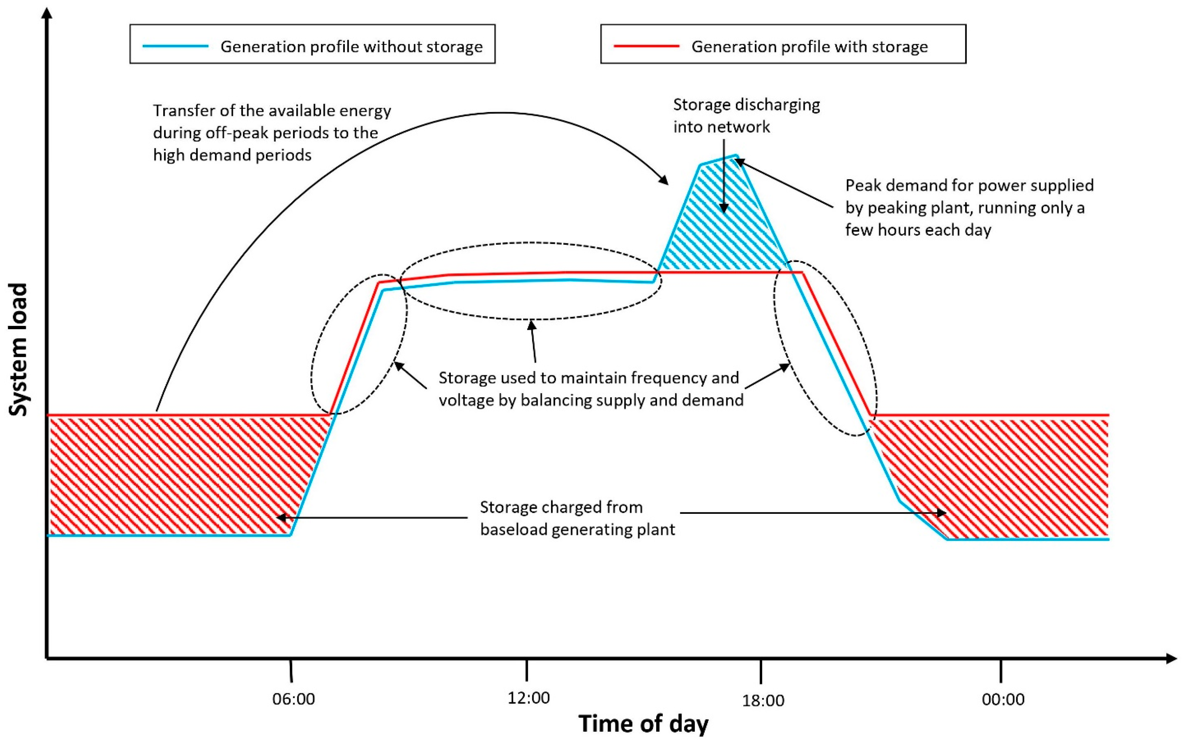
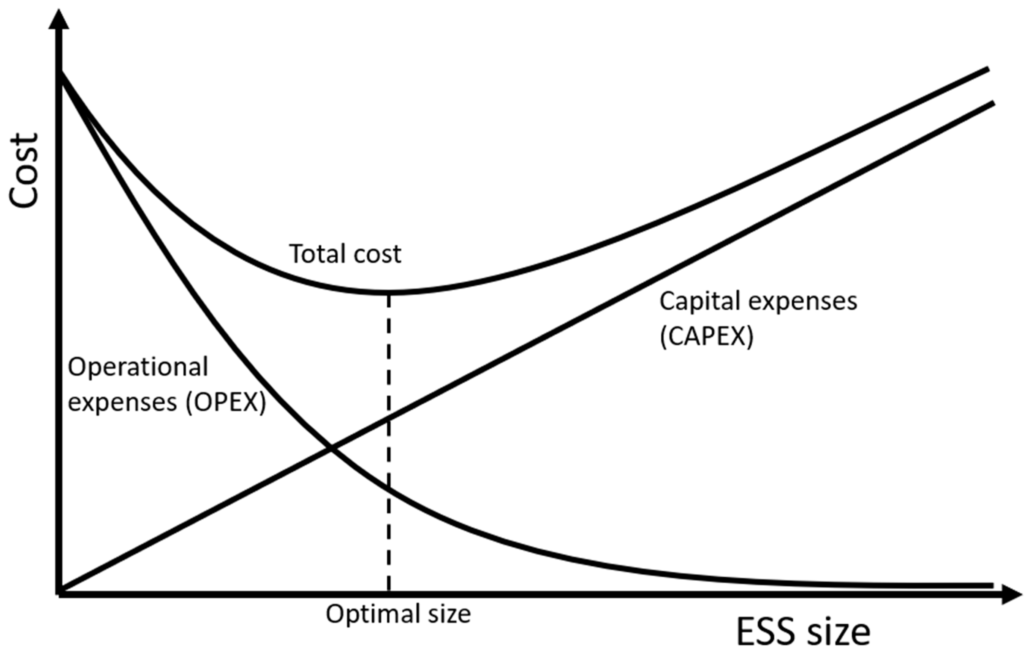

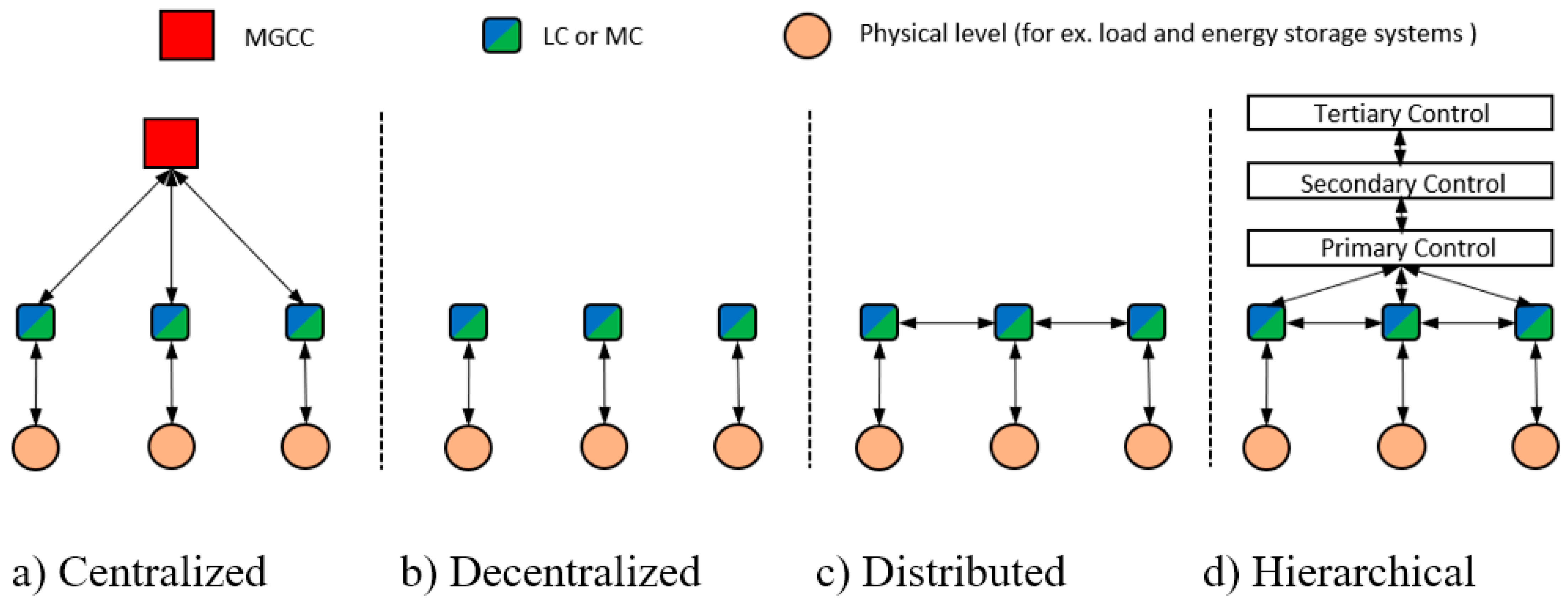


