Article

Accurate Computation of Mutual Inductance of Non Coaxial Pancake Coils

1
University Campus Bio-Medico of Rome, 00128 Rome, Italy
2
Department of Industrial and Information Engineering and Economy, University of L’Aquila, 67100 L’Aquila, Italy
3
Department of Computer Science, Electrical and Space Engineering, Luleå University of Technology, A2311 Luleå, Sweden
*
Author to whom correspondence should be addressed.
Energies 2021, 14(16), 4907; https://doi.org/10.3390/en14164907
Submission received: 25 June 2021 / Revised: 31 July 2021 / Accepted: 5 August 2021 / Published: 11 August 2021
(This article belongs to the Special Issue Electromagnetic Modeling in Power Electronics)

Abstract

:
The computation of self and mutual inductances of coils is a classic problem of electrical engineering. The accurate modeling of coupled coils has received renewed interest with the spread of wireless power transfer systems. This problem has been quite well addressed for coplanar or perfectly coaxial coils but it is known that the misalignment conditions easily lead to a sharp decrease in the efficiency. Hence, it is crucial to take misalignment into account in order to properly design the overall wireless power transfer system. This work presents a study to compute analytically the mutual inductance of non-coaxial pancake coils with parallel axes. The accuracy of the proposed methodology is tested by comparison with the numerical results obtained using the tool Fast-Henry. Then, a wireless power transfer system, comprising a full bridge inverter is considered, showing the impact of the misalignment on the coupling between two pancake coils and, thus, between the source and the load.

1. Introduction

The computation of mutual inductance between coaxial circular coils has been thoroughly addressed by many authors since the time of Maxwell who gave a formula for two circles whose axes intersect [1]. In [2,3] formulas for circular loops with parallel axes have been derived but, unfortunately, all these results can be applied only within a restricted range of parameters since they converge slowly in general [4].
Nowadays, numerical methods such as the finite element method (FEM) and boundary element method (BEM), allow calculation of the mutual inductance of realistic 3-D geometric arrangement of conductors in an accurate and fast way. However, analytic and semi-analytic methods are still of interest to address this problem as they considerably simplify the mathematical procedures, leading to a significant reduction in the computational effort [4]. General techniques have been developed over the years [5,6,7,8,9,10] which have been found to be useful in many different fields including eddy-current tomography [11], planar PCB inductors [12], coreless printed circuit board transformers [13], force and torque calculation [14,15], electromagnetic launchers [16], plasma science [17], and superconducting magnetic levitation [18]. Still, the methods presented in these works are finally based on a numerical computation [19,20,21].
The calculation of the mutual coupling between two coils with the spread of wireless power transfer (WPT) systems has received new interest. This problem has been quite well addressed for coplanar or perfectly coaxial coils [22,23] but it is known that the misalignment conditions easily lead to a sharp decrease in the efficiency. Misalignment can be either lateral or angular. In electrical vehicle charging systems, the most relevant is lateral misalignment. Hence, it becomes crucial to take this misalignment into account in order to properly design the overall WPT system [24,25,26]. In [27] the numerical solution proposed in [27] is applied to WPT system with many non-coaxial coils. While it is clear that the mutual inductance between non-coaxial coils can be computed by resorting to numerical integration [28], to authors’ knowledge no analytical solution has been found to this problem. An accurate expression of mutual inductance of Archimedean spiral coils was presented and verified experimentally in [21] but, again, a numerical integration is required. By avoiding numerical integration, the mutual inductance can be calculated faster which can be used for the system optimization, i.e., evaluate faster the impact of misalignment on the WPT system performance e.g., [29]. This work presents a study to compute analytically the mutual inductance of non-coaxial pancake coils with parallel axes. The proposed formula in a series form is verified against numerical results obtained by means of the inductance extraction program Fast–Henry [30]. Finally, the case-study of a WPT system comprising two non-coaxial coils and a converter is presented, pointing out the effect of the misalignment on the performance.

2. Theory

Consider the two air-cored parallel flat coils shown in Figure 1. The turns of the coils have radii a i ( i = 1 , , N ) and b j ( j = 1 , , M ), while the radial displacement between the coil axes and the vertical spacing between the coil planes are indicated with ρ and h, respectively. The overall mutual inductance of the coils is given by
M a b = i = 1 N j = 1 M Φ ( a i , b j , ρ ) ,
where Φ ( a , b , ρ ) is the flux linkage per unit current between two generic turns with radii a and b.
The goal of this section is to develop a rigorous procedure that allows analytical evaluation of the integral expression of Φ ( a , b , ρ ) , that is [22]
Φ ( a , b , ρ ) = π μ 0 a b 0 e λ h J 1 ( λ a ) J 1 ( λ b ) J 0 ( λ ρ ) d λ ,
where J m ( · ) is the mth-order Bessel function, and μ 0 is the magnetic permeability of free space. To this end, we first replace J 0 λ ρ with its ascending power series expansion ([31] Eq. 9.1.12)
J 0 λ ρ = n = 0 1 n λ ρ 2 n ( 2 n ) ! ! 2 ,
with ( 2 n ) ! ! being the double factorial 2 · 4 · 6 · 8 · · 2 n , and obtain
Φ ( a , b , ρ ) = π μ 0 a b n = 0 1 n ρ 2 n ( 2 n ) ! ! 2 0 e λ h J 1 ( λ a ) J 1 ( λ b ) λ 2 n d λ .
Next, applying the identity
λ 2 n e λ h = 2 n e λ h h 2 n ,
makes it possible to express the flux linkage between two arbitrary turns as
Φ ( a , b , ρ ) = n = 0 1 n ρ 2 n ( 2 n ) ! ! 2 2 n h 2 n Φ ( a , b , 0 ) ,
where Φ ( a , b , 0 ) is the flux corresponding to perfect alignment. An explicit representation for Φ ( a , b , 0 ) may be found starting from replacing the product of first-order Bessel functions with its finite integral representation according to Gegenbauer’s addition theorem, namely [32] (Eq. 11.41.17)
J 1 ( λ a ) J 1 ( λ b ) = 1 π 0 π J 0 ( λ c ) cos ϕ d ϕ ,
where ϕ is the variable of integration, and
c = a 2 + b 2 2 a b cos ϕ .
This allows writing of the expression
Φ ( a , b , 0 ) = μ 0 a b 0 π cos ϕ d ϕ 0 e λ h J 0 λ c d λ ,
whose integral on the right-hand side is known and given by [33]
0 e λ d J 0 ( λ c ) d λ = 1 d 2 + ε ,
being d 2 = a 2 + b 2 + h 2 , and ε = 2 a b cos ϕ . Expanding (10) into a power series of ε , as follows
1 d 2 + ε = 1 d m = 0 ( 1 ) m ( 2 m 1 ) ! ! ( 2 m ) ! ! ε d 2 m
allows transformation of (9) into
Φ ( a , b , 0 ) = μ 0 a b d m = 1 ( 1 ) m ( 2 m 1 ) ! ! ( 2 m ) ! ! 2 a b d 2 m 0 π cos m + 1 ϕ d ϕ ,
where it has been taken into account that the finite integral over ϕ is non-null only for m 0 . Finally, since it holds [34]
0 π cos m + 1 ϕ = π m ! ! / ( m + 1 ) ! ! , odd m 0 , even m
after setting m = 2 l + 1 , it is found that
Φ ( a , b , 0 ) = π μ 0 a b d l = 0 ( 4 l + 1 ) ! ! ( 2 l + 2 ) ! ! ( 2 l ) ! ! a b d 2 2 l + 1 .
Combining (14) with (6) provides an explicit expression for the mutual inductance of two misaligned turns with radii a and b, that is
Φ ( a , b , ρ ) = π μ 0 a b d n = 0 1 n ρ 2 n ( 2 n ) ! ! 2 l = 0 ( 4 l + 1 ) ! ! ( 2 l + 2 ) ! ! ( 2 l ) ! ! ( a b ) 2 l + 1 2 n h 2 n 1 ( a 2 + b 2 + h 2 ) 2 l + 1 ,
which, since it yields
2 n h 2 n 1 ( a 2 + b 2 + h 2 ) 2 l + 1 = ( 2 n ) ! ( 2 l ) ! m = 0 n ( 1 ) m + n 2 2 m ( 2 l + m + n ) ! ( n m ) ! ( 2 m ) ! · h 2 m d 2 ( 2 l + m + n + 1 )
becomes
Φ ( a , b , ρ ) = π μ 0 a b d n = 0 ( 2 n 1 ) ! ! ( 2 n ) ! ! ρ d 2 n l = 0 ( 4 l + 1 ) ! ! l ! ( l + 1 ) ! ( 2 l ) ! a b 2 d 2 2 l + 1 f l n 2 h d ,
where
f l n ( x ) = m = 0 n ( 1 ) m ( 2 l + m + n ) ! ( n m ) ! ( 2 m ) ! x 2 m .
Use of (17) and (18) in conjunction with (1) provides the mutual inductance of two parallel non-coaxial pancake coils. Moreover, expression (14) alone may be also applied to the computation of the overall self-inductance of each coil. For instance, for the coil at the bottom of Figure 1, it yields [22]
L a = i = 1 N L t ( a i ) + 2 i = 1 N j = i + 1 N Φ ( a i , a j , 0 ) ,
with L t ( a ) being the self-inductance of a thin-wire circular loop with radius a, given by [22,35]
L t ( a ) = μ 0 a log 8 a r w 2 ,
where r w is the wire radius. It should be observed that both the integral expression of Φ ( a , b , ρ ) and formula (20) are valid subject to the thin-wire assumption, which holds when r w is negligible if compared to the radii of the turns.

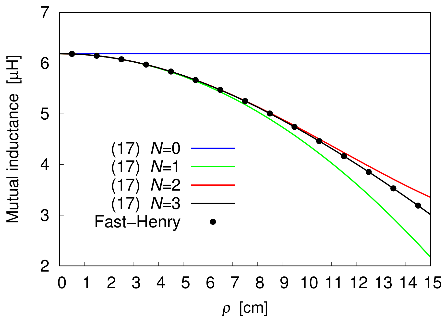
3. Results and Discussion

To test the developed theory, the derived Formula (17) is first applied to the computation of the flux linkage between two identical coils made up of 10 turns. For each coil, the radius of the inner turn is taken to be equal to 3 cm, while the spacing between the edges of two adjacent turns is 2 cm. The mutual inductance is calculated against the radial distance ρ , and the obtained results, illustrated in Figure 2 and Figure 3, are compared with the outcomes from the multipole-accelerated three-dimensional inductance extraction program Fast-Henry. Figure 2 depicts ρ profiles of the mutual inductance corresponding to h = 10 cm, with the truncation index N of the outer sum in (17) taken as a parameter. Thus, the figure illustrates the effect of adding a higher-order term to the truncated power series expansion of the flux, seen as a function of ρ . To ensure highly accurate computation of the nth term of the expansion, the inner sequence of partial sums in (17) is terminated when the relative difference between the two last partial sums is smaller than a specified tolerance, which is assumed to be 10 12 . As is evident from the analysis of the plotted curves, the data arising from using the partial sum in (17) with N = 3 agree well with those produced by the Fast-Henry solver. As a consequence, the sequence of partial sums converges to the exact solution as N is increased. Figure 2 also points out that, for a given value of the truncation index N, the accuracy of the outcomes from (17) is affected by the misalignment between the coils, and that, in particular, it worsens as the misalignment increases. However, further increasing N makes it possible to achieve a high degree of accuracy of the results of the computation regardless of the value of the misalignment. For instance, in the 0 < ρ < 15 cm range, the choice of N = 8 ensures that the relative difference between the last two elements of the outer sequence of partial sums in (17) is always smaller than 10 8 . This means that setting the desired tolerance of 10 8 for stopping the outer sequence of partial sums always leads to truncate the series at N = 8 .
Convergence of (17) is also confirmed by the ρ profiles plotted in Figure 3. Here, the same coils as in the previous example are considered, while their planes are now separated by the distance h = 20 cm. As can be seen, even if the distance has been doubled, perfect matching is still observed between the outcomes of Fast-Henry solver and the trend arising from the proposed series-form solution truncated at N = 3 . This suggests that the rate of convergence of (17) is not affected by a variation of h.

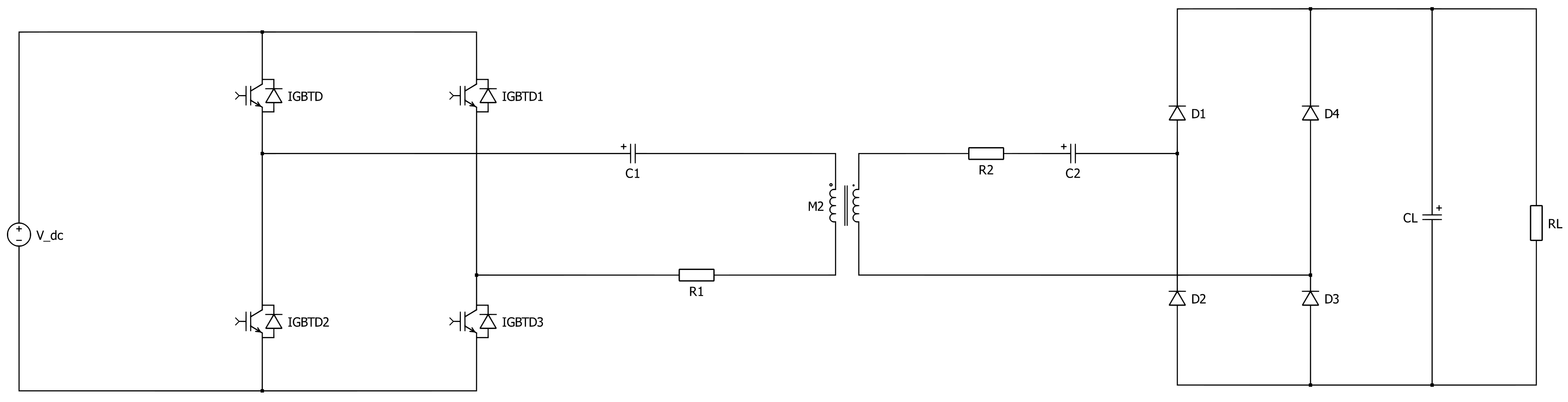
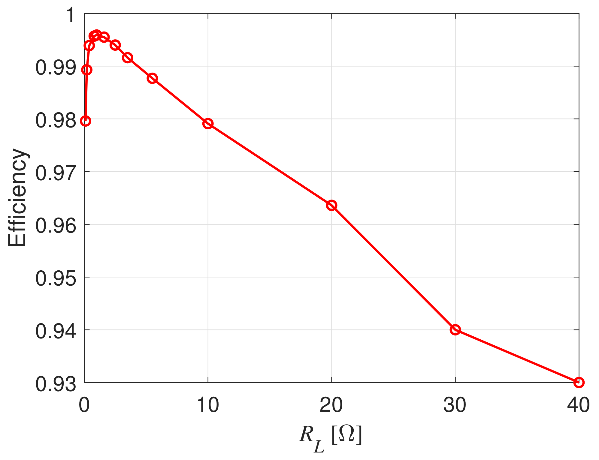
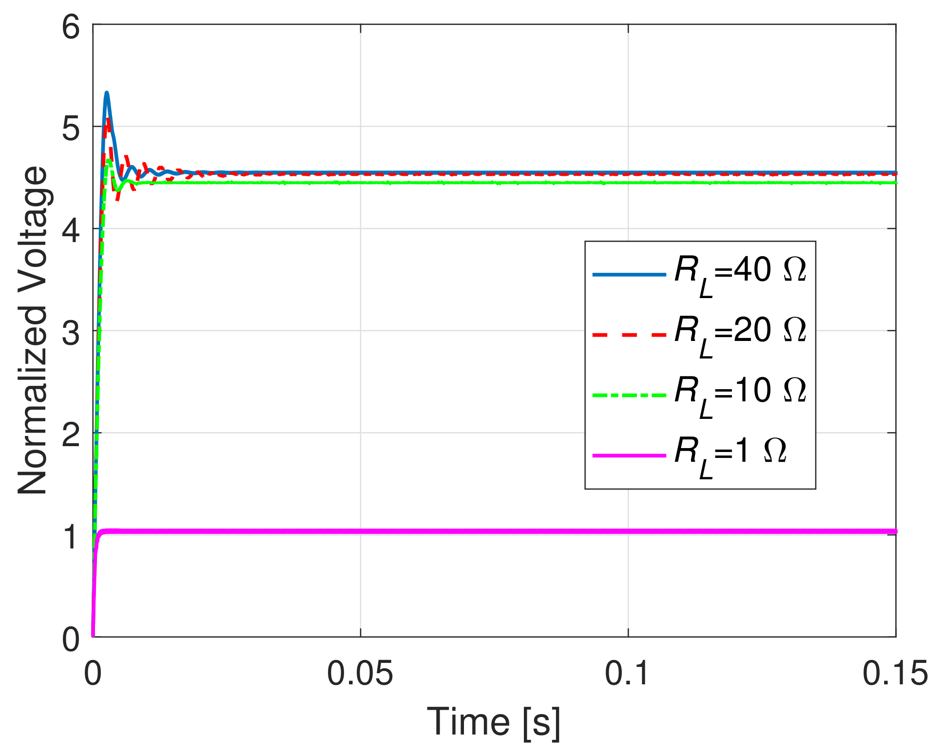
4. WPT System with a Full Bridge Inverter

A possible application of the coupled coils system presented is in the Wireless Power Transfer (WPT) area. The purpose of this paragraph is to provide an example where a couple of coils are employed in order to transfer an amount of power from a source to a distant load. The WPT coupling between two pancake coils is studied performing several simulations using the Plexim software “PLECS”; the target is to compute the load voltage over a load resistance R L due to the exchange of power between two distant coupled coils [36]. The schematic of the configuration under investigation is shown in Figure 4. The central element of the circuit represents the coupling between a primary coil having a self inductance L 1 and the secondary coil with a self inductance L 2 ; the effect of the mutual coupling is described by the mutual inductance parameter L m that, besides depending on the geometry and the materials employed for each single coil, depends certainly on the distance and the misalignment between the coils.
The primary coil and its series resonant capacitor C 1 are connected to an ideal full-bridge inverter. The secondary coil and its series resonant capacitor C 2 are connected to an ideal full-bridge rectifier which converts the induced AC voltage of the secondary coil to DC voltage. The components R 1 and R 2 represent primary and secondary effective series DC resistances, respectively, which in this case are equal because the geometry is the same for both the coils. The load capacitor C L is a filter capacitor. The full bridge inverter is supposed to be operated by a switching frequency f s = 20 kHz [36]; hence, a bipolar voltage is generated by the inverter on the primary side. The global voltage applied to the primary side is sketched in Figure 5. In order to guarantee the zero voltage switching (ZVS) operation of the inverter, the primary side resonant frequency f r 1 , determined by C 1 and L 1 , is chosen slightly smaller than the switching frequency [36].
f s = 1.05 f r 1 = 1.05 2 π L 1 C 1
The secondary side resonant frequency f r 2 , determined by C 2 and L 2 , is tuned exactly to the switching frequency:
f r 2 = 1 2 π L 2 C 2 = f s
It is clear that the capacitors values C 1 and C 2 can be easily determined by (21) and (22) knowing only the self inductances values and the inverter switching frequency. Twelve different configurations have been considered for the simulations, varying both the distances and the misalignments between the coils under observation. All the set-up parameters are reported in Table 1 and the different configurations are reported in Table 2.
The load voltage on the resistance R L , normalized to the DC source voltage, is computed and illustrated, for each value of the misalignment, in Figure 6, Figure 7 and Figure 8. It is clearly seen that the misalignment has a significant impact on the rectified load voltage. Furthermore, for the case h = 10 cm, ρ = 0.5 cm and L m = 6.18 μ H, the efficiency for increasing values of the load resistance R L has been evaluated; the efficiency is defined as the average power delivered to the load divided by the average power supplied by the full-bridge inverter. It is easy to verify from Figure 9 that the optimal load resistance for this specific configuration is around R L = 1.1 Ω .
As a last test, the load voltage was computed considering four different load conditions: R L = [ 1 , 10 , 20 , 40 ] Ω , when: h = 10 cm, ρ = 0.5 cm and L m = 6.18 μ H; the results are shown in Figure 10.

5. Conclusions

This work has presented a study to compute analytically the mutual inductance of non-coaxial pancake coils with parallel axes. The proposed formula was tested by comparison with the numerical results obtained using the tool Fast-Henry. Then, the proposed formula was used to compute the mutual inductance between two pancake coils in a wireless power transfer system, comprising a full bridge inverter. The impact of the misalignment on the coupling between the source and the load was verified and quantified.

Author Contributions

Conceptualization, M.P., F.L., D.R., G.A. and J.E.; methodology, M.P., F.L., D.R., G.A. and J.E.; software, M.P., F.L. and D.R.; validation, M.P., F.L. and D.R.; formal analysis, M.P., F.L., D.R., G.A. and J.E.; investigation, M.P., F.L., D.R. and G.A.; resources, M.P., G.A. and J.E.; data curation, M.P., F.L., D.R. and G.A.; writing—original draft preparation, M.P., F.L. and G.A.; writing—review and editing, M.P., F.L., D.R., G.A. and J.E.; visualization, M.P., F.L. and G.A.; supervision, M.P. and G.A.; project administration, G.A.; funding acquisition, G.A. All authors have read and agreed to the published version of the manuscript.

Funding

This research received no external funding.

Acknowledgments

The authors are grateful to Ulrike Grossner and Ivana Kovacevic-Badstuebner for their hints which have allowed improvemnet of the quality of the paper.

Conflicts of Interest

The authors declare no conflict of interest.

Abbreviations

The following abbreviations are used in this manuscript:
MDPIMultidisciplinary Digital Publishing Institute
DOAJDirectory of open access journals
EMElectromagnetic
PEPower electronics
PESPower electronic systems
HFHigh Frequency
LFLow Frequency
SiCSilicon Carbide
PEECPartial Element Equivalent Circuit
FEMFinite Element
3-DThree-dimensional

References

  1. Maxwell, J.C. A Treatise on Electricity and Magnetism; Dover: New York, NY, USA, 1954. [Google Scholar]
  2. Butterworth, S. On the coefficients of mutual induction of eccentric coils. Philos. Mag. J. Sci. 1916, 31, 443–454. [Google Scholar] [CrossRef]
  3. Snow, C. Formulas for Computing Capacitance and Inductance; Bureau of Standards Circular 544: Washington, DC, USA, 1954. [Google Scholar]
  4. Babic, S.; Sirois, F.; Akyel, C.; Girardi, C. Mutual Inductance Calculation Between Circular Filaments Arbitrarily Positioned in Space: Alternative to Grover’s Formula. IEEE Trans. Magn. 2010, 46, 3591–3600. [Google Scholar] [CrossRef]
  5. Babic, S.; Akyel, C. New analytic-numerical solutions for the mutual inductance of two coaxial circular coils with rectangular cross section in air. IEEE Trans. Magn. 2006, 42, 1661–1669. [Google Scholar] [CrossRef]
  6. Babic, S.I.; Akyel, C. Calculating Mutual Inductance Between Circular Coils With Inclined Axes in Air. IEEE Trans. Magn. 2008, 44, 1743–1750. [Google Scholar] [CrossRef]
  7. Conway, J.T. Inductance calculations for noncoaxial coils using Bessel functions. IEEE Trans. Magn. 2007, 43, 1023–1034. [Google Scholar] [CrossRef]
  8. Conway, J.T. Noncoaxial Inductance Calculations Without the Vector Potential for Axisymmetric Coils and Planar Coils. IEEE Trans. Magn. 2008, 44, 453–462. [Google Scholar] [CrossRef]
  9. Engel, T.; Rohe, S. A comparison of single-layer coaxial coil mutual inductance calculations using finite-element and tabulated methods. IEEE Trans. Magn. 2006, 42, 2159–2163. [Google Scholar] [CrossRef]
  10. Cirimele, V.; Torchio, R.; Virgillito, A.; Freschi, F.; Alotto, P. Challenges in the Electromagnetic Modeling of Road Embedded Wireless Power Transfer. Energies 2019, 12, 2677. [Google Scholar] [CrossRef] [Green Version]
  11. Su, Y.P.; Liu, X.; Hui, S.Y.R. Mutual Inductance Calculation of Movable Planar Coils on Parallel Surfaces. IEEE Trans. Power Electron. 2009, 24, 1115–1123. [Google Scholar] [CrossRef]
  12. Sonntag, C.L.W.; Lomonova, E.A.; Duarte, J.L. Implementation of the Neumann formula for calculating the mutual inductance between planar PCB inductors. In Proceedings of the 2008 18th International Conference on Electrical Machines, Vilamoura, Portugal, 6–9 September 2008; pp. 1–6. [Google Scholar] [CrossRef] [Green Version]
  13. Tang, S.; Hui, S.; Chung, H. A low-profile wide-band three-port isolation amplifier with coreless printed-circuit-board (PCB) transformers. IEEE Trans. Ind. Electron. 2001, 48, 1180–1187. [Google Scholar] [CrossRef]
  14. Ravaud, R.; Lemarquand, G.; Lemarquand, V. Force and Stiffness of Passive Magnetic Bearings Using Permanent Magnets. Part 1: Axial Magnetization. IEEE Trans. Magn. 2009, 45, 2996–3002. [Google Scholar] [CrossRef] [Green Version]
  15. Ravaud, R.; Lemarquand, G.; Lemarquand, V. Force and Stiffness of Passive Magnetic Bearings Using Permanent Magnets. Part 2: Radial Magnetization. IEEE Trans. Magn. 2009, 45, 3334–3342. [Google Scholar] [CrossRef]
  16. Keyi, Z.; Bin, L.; Zhiyuan, L.; Shukang, C.; Ruiping, Z. Inductance Computation Consideration of Induction Coil Launcher. IEEE Trans. Magn. 2009, 45, 336–340. [Google Scholar] [CrossRef]
  17. Engel, T.G.; Mueller, D.W. High-Speed and High-Accuracy Method of Mutual-Inductance Calculations. IEEE Trans. Plasma Sci. 2009, 37, 683–692. [Google Scholar] [CrossRef]
  18. Kajikawa, K.; Yokoo, R.; Tomachi, K.; Enpuku, K.; Funaki, K.; Hayashi, H.; Fujishiro, H. Numerical Evaluation of Pulsed Field Magnetization in a Bulk Superconductor Using Energy Minimization Technique. IEEE Trans. Appl. Supercond. 2008, 18, 1557–1560. [Google Scholar] [CrossRef]
  19. Babic, S.; Martinez, J.; Akyel, C.; Babic, B. Mutual Inductance Calculation between Misalignment Coils for Wireless Power Transfer of Energy. Prog. Electromagn. Res. M 2014, 38, 91–102. [Google Scholar] [CrossRef] [Green Version]
  20. Luo, Z.; Wei, X. Mutual Inductance Analysis of Planar Coils with Misalignment for Wireless Power Transfer Systems in Electric Vehicle. In Proceedings of the 2016 IEEE Vehicle Power and Propulsion Conference (VPPC), Hangzhou, China, 17–20 October 2016; pp. 1–6. [Google Scholar] [CrossRef]
  21. Liu, S.; Su, J.; Lai, J. Accurate Expressions of Mutual Inductance and Their Calculation of Archimedean Spiral Coils. Energies 2019, 12, 2017. [Google Scholar] [CrossRef] [Green Version]
  22. Zierhofer, C.M.; Hochmair, E.S. Geometric approach for coupling enhancement of magnetically coupled coils. IEEE Trans. Biomed. Eng. 1996, 43, 708–714. [Google Scholar] [CrossRef]
  23. Parise, M.; Antonini, G.; Romano, D. On the Flux Linkage between Pancake Coils in Resonance-Type Wireless Power Transfer Systems. Int. J. Antennas Propag. 2020, 2020, 1–6. [Google Scholar] [CrossRef]
  24. Simonazzi, M.; Sandrolini, L.; Zarri, L.; Reggiani, U.; Alberto, J. Model of Misalignment Tolerant Inductive Power Transfer System for EV Charging. In Proceedings of the 2020 IEEE 29th International Symposium on Industrial Electronics (ISIE), Delft, The Netherlands, 17–19 June 2020; pp. 1617–1622. [Google Scholar] [CrossRef]
  25. Fontana, N.; Brizi, D.; Barmada, S.; Monorchio, A. A Methodology for Efficiency Recovering in Wireless Power Transfer Applications with Misalignment. In Proceedings of the 2020 XXXIIIrd General Assembly and Scientific Symposium of the International Union of Radio Science, Rome, Italy, 29 August–5 September 2020. [Google Scholar] [CrossRef]
  26. ElGhanam, E.; Hassan, M.; Osman, A.; Kabalan, H. Design and Performance Analysis of Misalignment Tolerant Charging Coils for Wireless Electric Vehicle Charging Systems. World Electr. Veh. J. 2021, 12, 89. [Google Scholar] [CrossRef]
  27. Steckiewicz, A.; Stankiewicz, J.M.; Choroszucho, A. Numerical and Circuit Modeling of the Low-Power Periodic WPT Systems. Energies 2020, 13, 2651. [Google Scholar] [CrossRef]
  28. Tal, N.; Morag, Y.; Levron, Y. Magnetic Induction Antenna Arrays for MIMO and Multiple-Frequency Communication Systems. Prog. Electromagn. Res. C 2017, 75, 155–167. [Google Scholar] [CrossRef] [Green Version]
  29. Miller, J.M.; Onar, O.C.; Chinthavali, M. Primary-Side Power Flow Control of Wireless Power Transfer for Electric Vehicle Charging. IEEE J. Emerg. Sel. Top. Power Electron. 2015, 3, 147–162. [Google Scholar] [CrossRef]
  30. Kamon, M.; Tsuk, M.J.; White, J.K. FASTHENRY: A multipole-accelerated 3-D inductance extraction program. IEEE Trans. Microw. Theory Tech. 1994, 42, 1750–1758. [Google Scholar] [CrossRef]
  31. Abramowitz, M.; Stegun, I.A. Handbook of Mathematical Functions: With Formulas, Graphs, and Mathematical Tables; Courier Corporation: Washington, DC, USA, 1964; Volume 55. [Google Scholar]
  32. Watson, G.N. A Treatise on the Theory of Bessel Functions; Cambridge mathematical library, Cambridge University Press: Cambridge, UK, 1944. [Google Scholar]
  33. Erdelyi, A. Tables of Integral Transforms; McGraw-Hill: New York, NY, USA, 1954; Volume 1. [Google Scholar]
  34. Gradshteyn, I.S.; Ryzhik, I.M. Table of Integrals, Series, and Products; Academic Press: New York, NY, USA, 2007. [Google Scholar]
  35. Paul, C.R. Inductance: Loop and Partial; John Wiley & Sons: Hoboken, NJ, USA, 2010. [Google Scholar]
  36. Rim, C.T.; Mi, C. Wireless Power Transfer for Electric Vehicles and Mobile Devices; JohnWiley & Sons: Hoboken, NJ, USA, 2017. [Google Scholar]
Figure 1. Sketch of two parallel pancake coils.
Energies 14 04907 g001
Figure 2. Mutual inductance of two 10-turn coils spaced 10 cm apart, as a function of ρ .
Energies 14 04907 g002
Figure 3. Mutual inductance of two 10-turn coils spaced 20 cm apart, as a function of ρ .
Energies 14 04907 g003
Figure 4. Circuit scheme of the inductive power transfer system which includes an inverter for the primary coil and a rectifier for the secondary coil.
Energies 14 04907 g004
Figure 5. Voltage applied to the WPT system.
Energies 14 04907 g005
Figure 6. Load normalized voltages with h = 10 cm.
Energies 14 04907 g006
Figure 7. Load normalized voltages with h = 15 cm.
Energies 14 04907 g007
Figure 8. Load normalized voltages with h = 20 cm.
Energies 14 04907 g008
Figure 9. WPT efficiency varying the load resistance R L and assuming h = 10 cm, ρ = 0.5 cm.
Energies 14 04907 g009
Figure 10. Load normalized voltages assuming h = 10 cm, ρ = 0.5 cm and varying the load resistance R L .
Energies 14 04907 g010
Table 1. Circuit parameters.
Switching frequency f s = 20 kHz
Primary capacitor C 1 = 4.1 μ F
Primary resistance R 1 = 1.66 m Ω
Secondary capacitor C 2 = 3.73 μ F
Secondary resistance R 2 = 1.66 m Ω
Self inductances L 1 = L 2 = 17 μ H
Load capacitor C L = 300 μ F
Load resistance R L = 40   Ω
Conductors radius r w = 5 mm
Table 2. Test configurations.
Distance h [cm]Misalignment ρ [cm] L m [ μ H]
10 0.5 6.18
10 3.5 5.97
10 6.5 5.47
109 4.88
150 3.87
15 3.5 3.76
15 6.25 3.52
15 8.5 3.24
200 2.52
20 3.25 2.47
206 2.34
20 8.5 2.18
Publisher’s Note: MDPI stays neutral with regard to jurisdictional claims in published maps and institutional affiliations.

