
Experimental Analysis of the Arrays of Macro Fiber Composite Patches for Rotational Piezoelectric Energy Harvesting from a Shaft


Abstract
:
1. Introduction
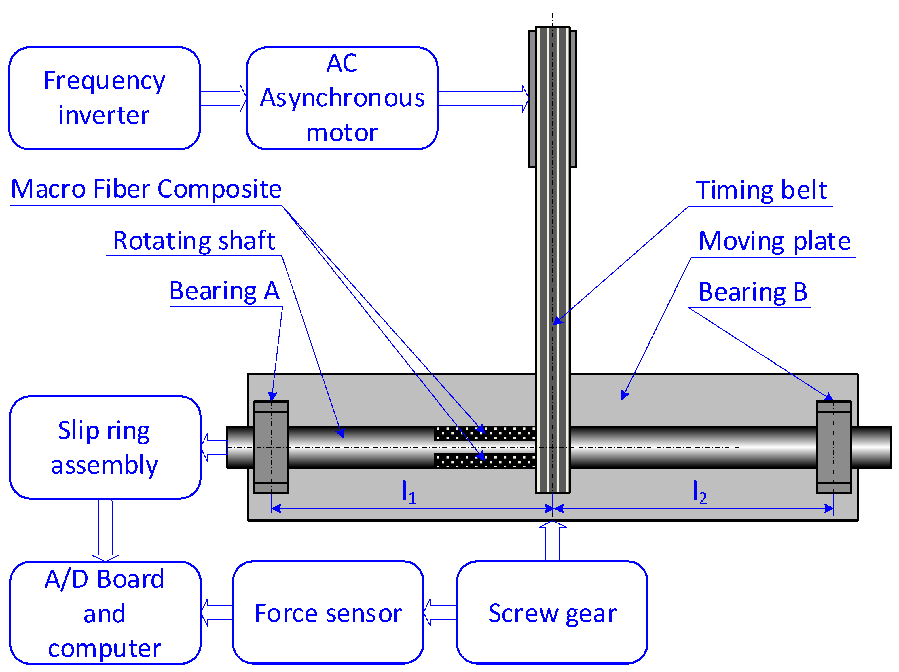
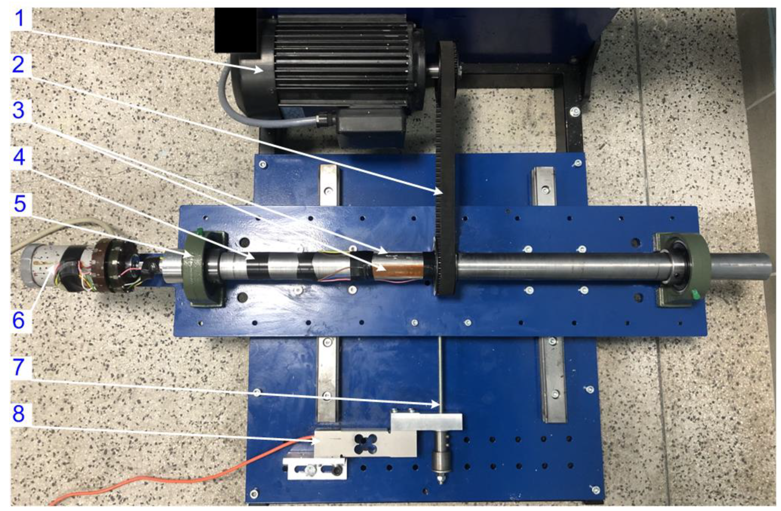
2. Laboratory Setup
3. Results
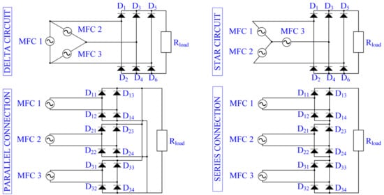
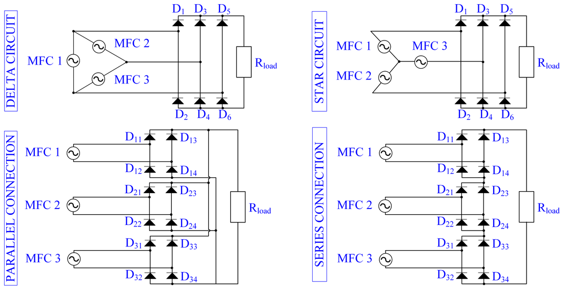
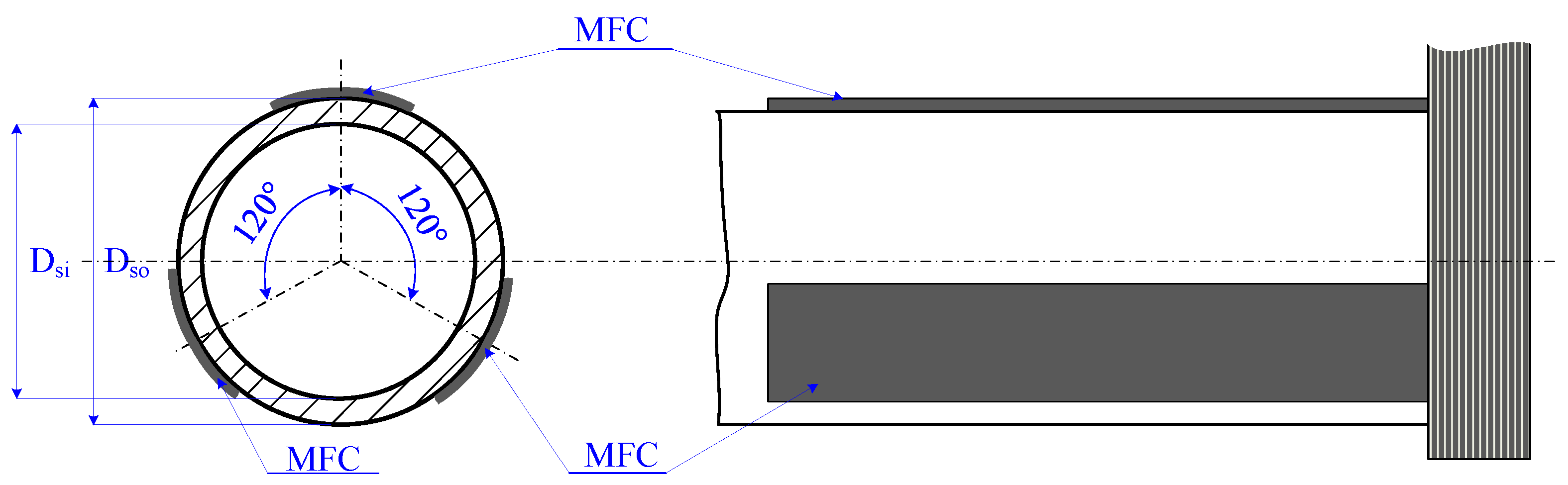
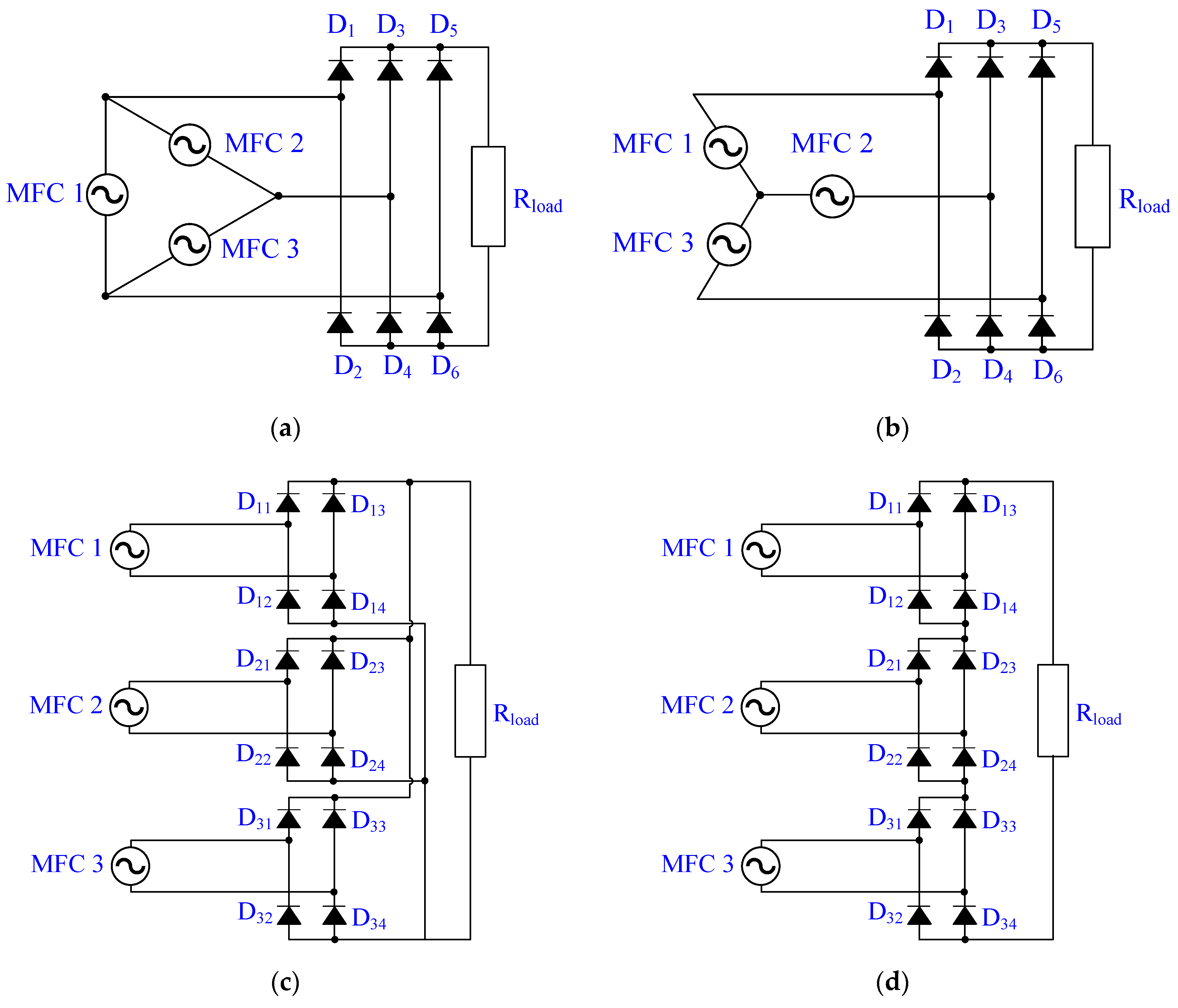
3.1. Array of Macro Fiber Composite Patches
- MFC patches were connected with each other using a delta circuit. An MFC delta circuit was equipped with a three-phase rectifier (Figure 4a);
- MFC patches were connected with each other using a star circuit. An MFC star circuit was equipped with a three-phase rectifier (Figure 4b);
- MFC patches were not connected with each other. Each MFC patch was equipped with a full-bridge rectifier. Subsystems consisting of MFC and rectifier were parallel connected (Figure 4c);
- MFC patches were not connected with each other. Each MFC patch was equipped with a full-bridge rectifier. Subsystems consisting of MFC and rectifier were series connected (Figure 4d).
3.2. Conditions of Laboratory Experiments
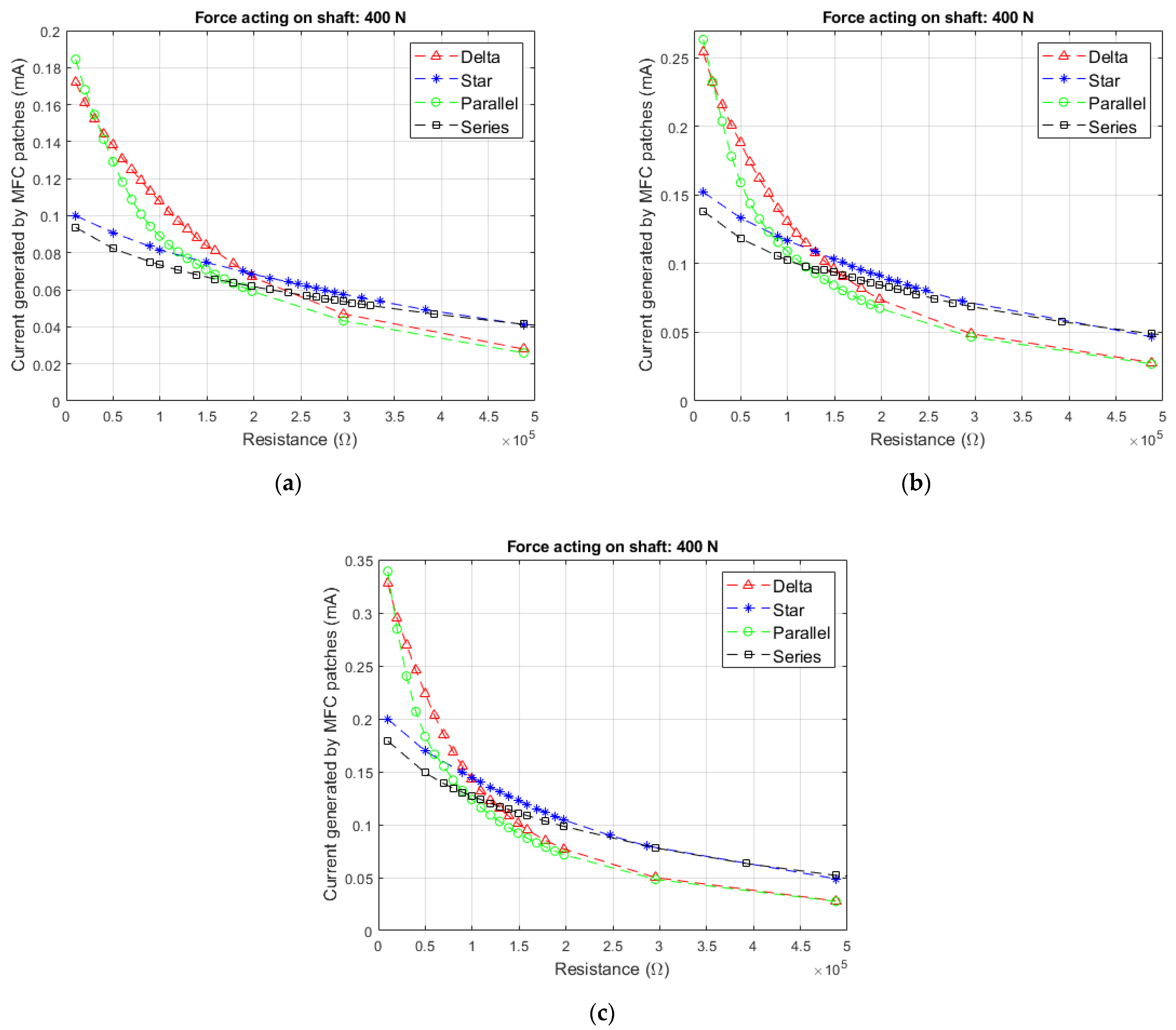
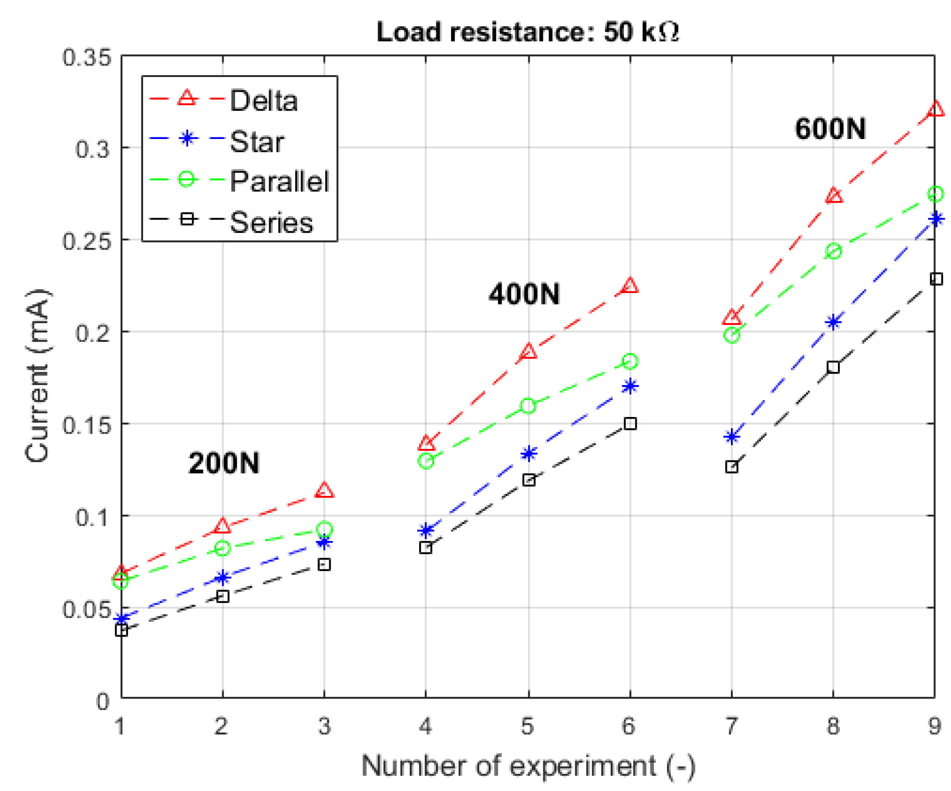
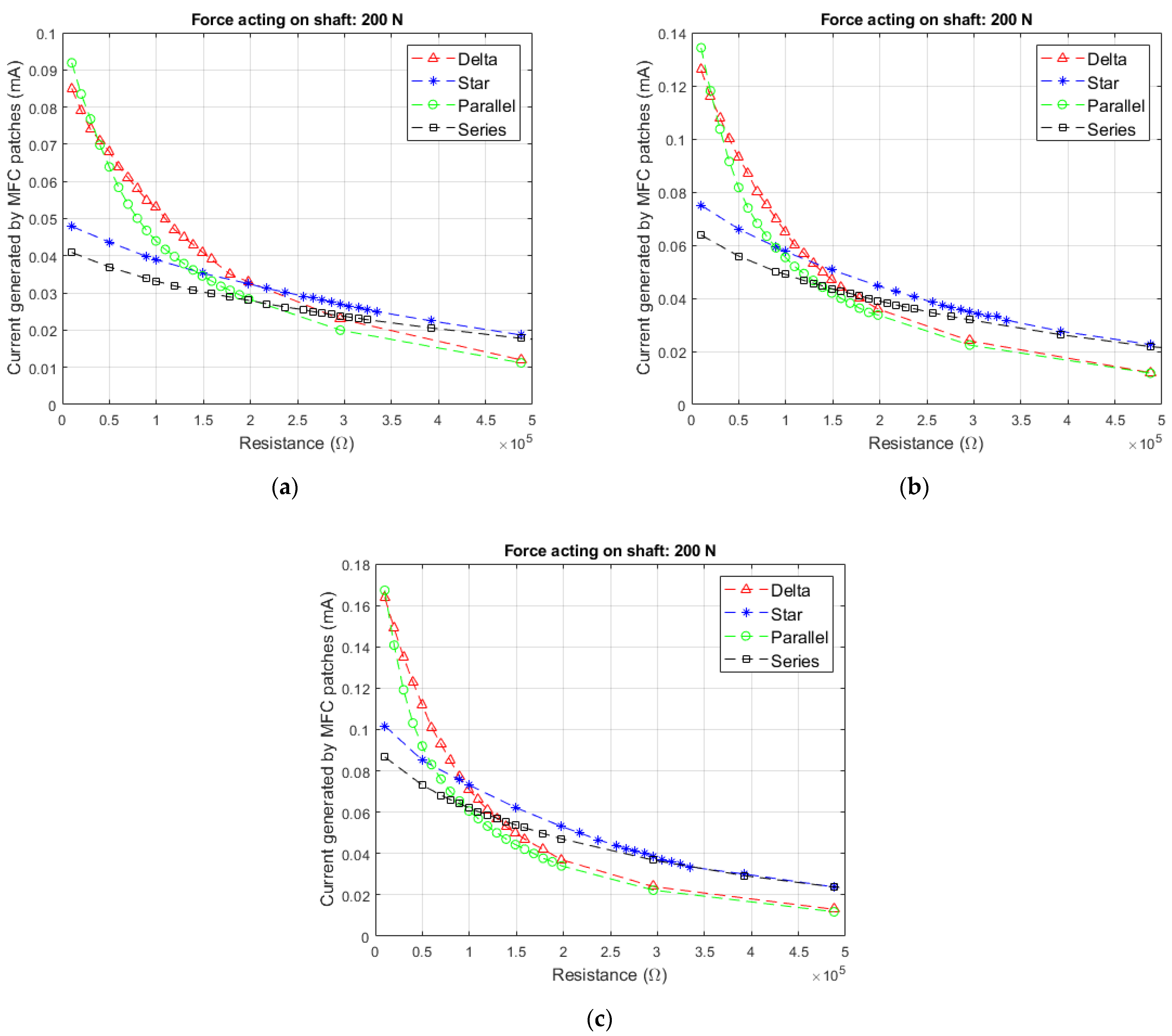
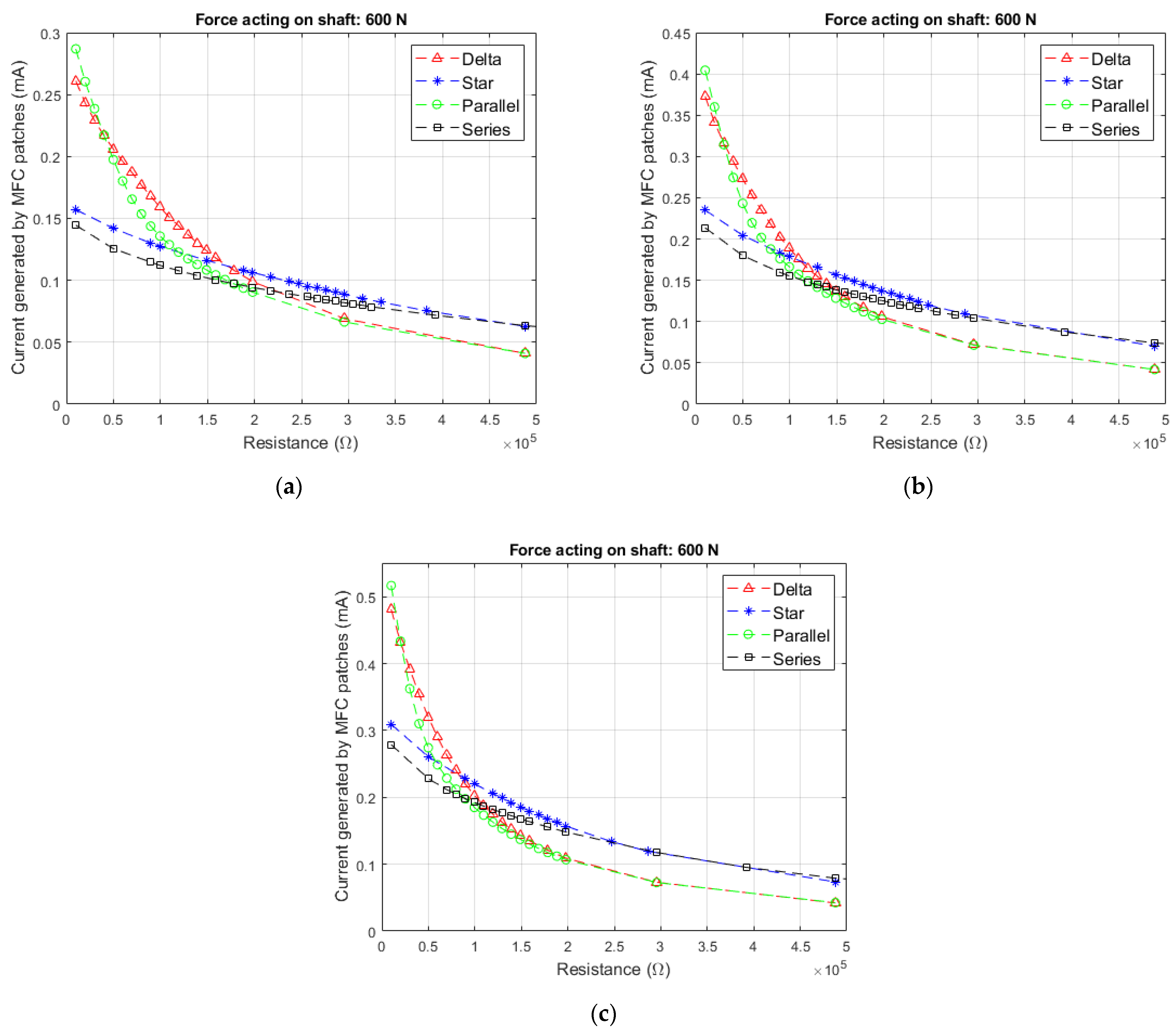
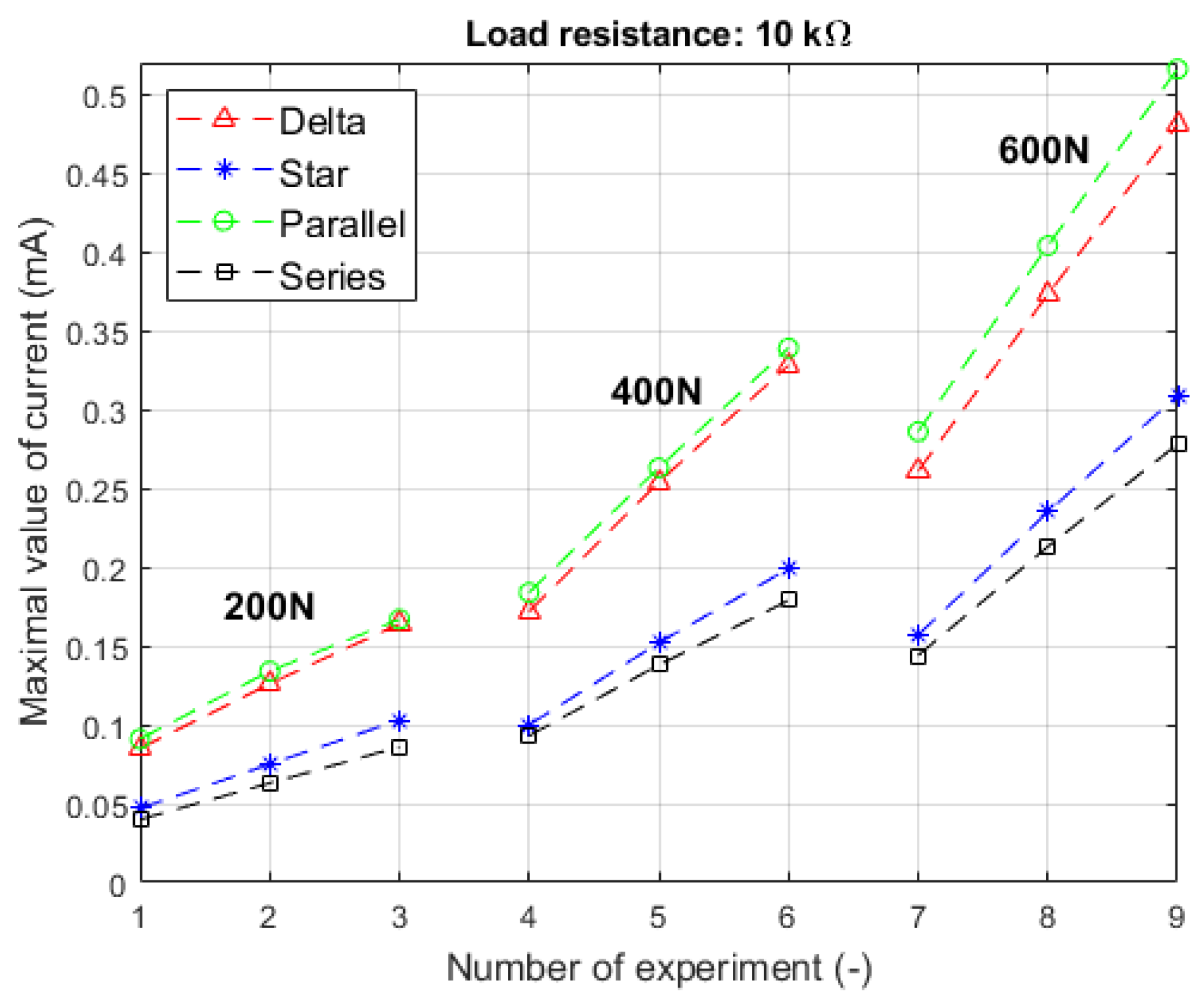
3.3. Current Generated by MFC Arrays
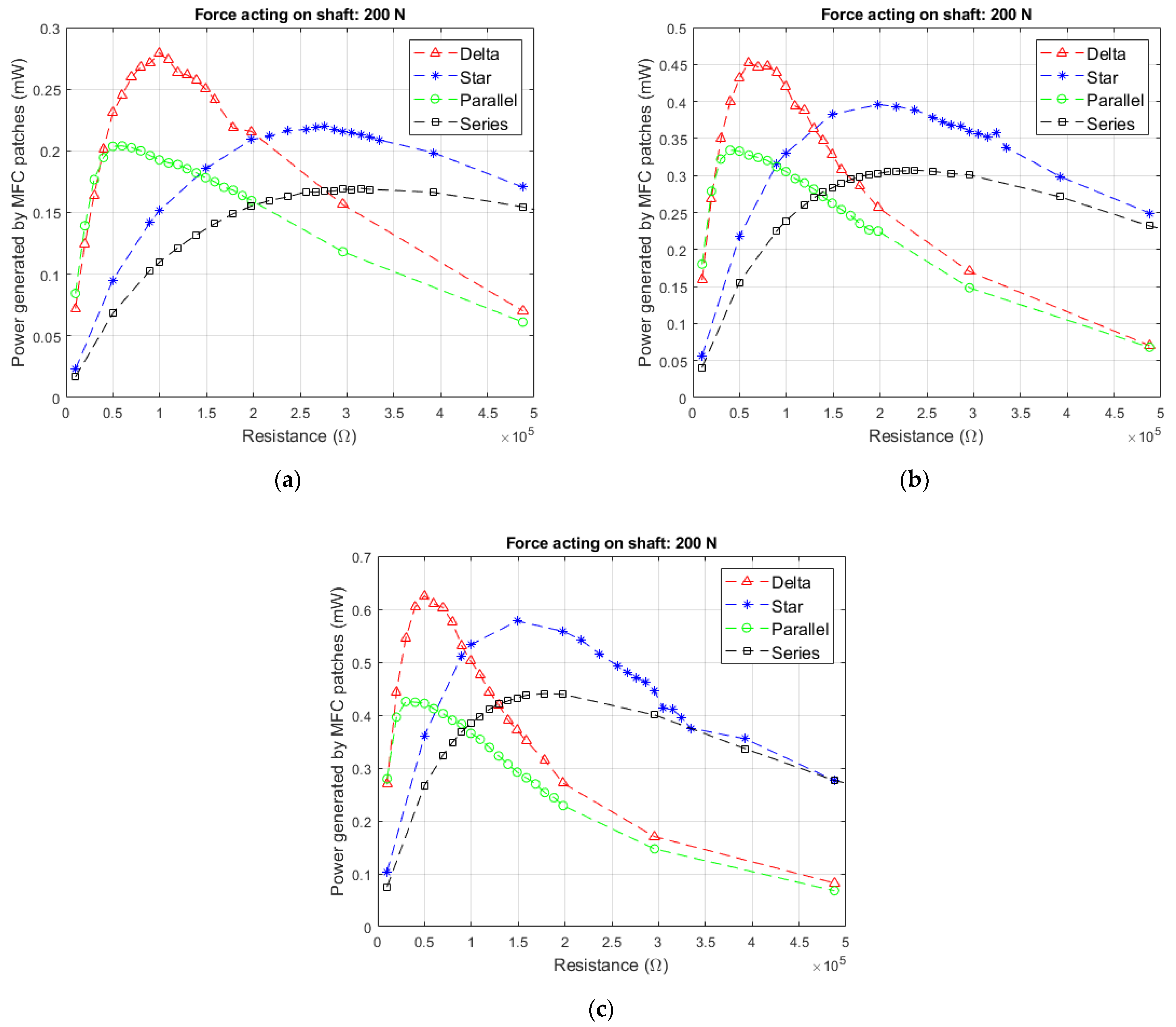
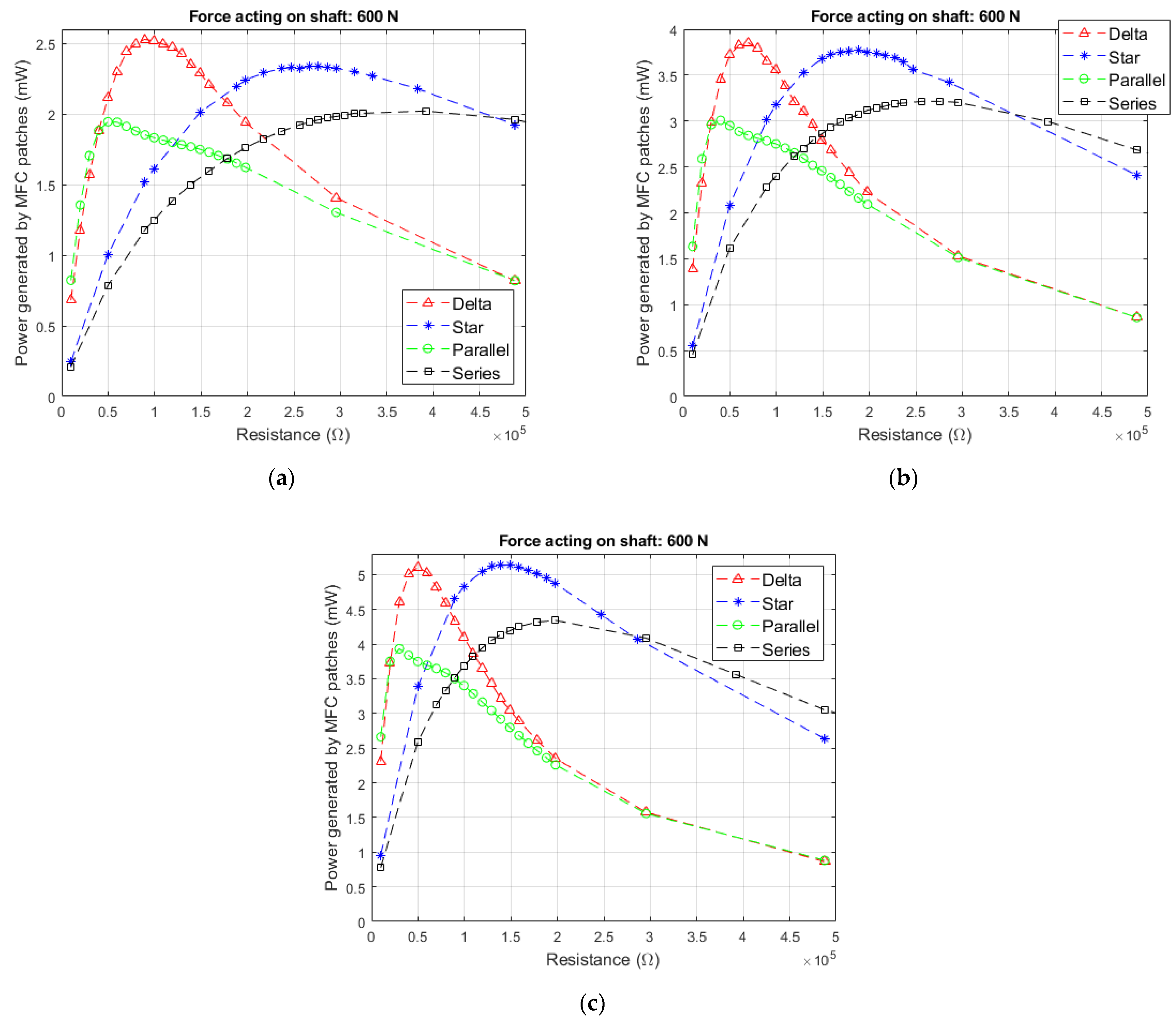
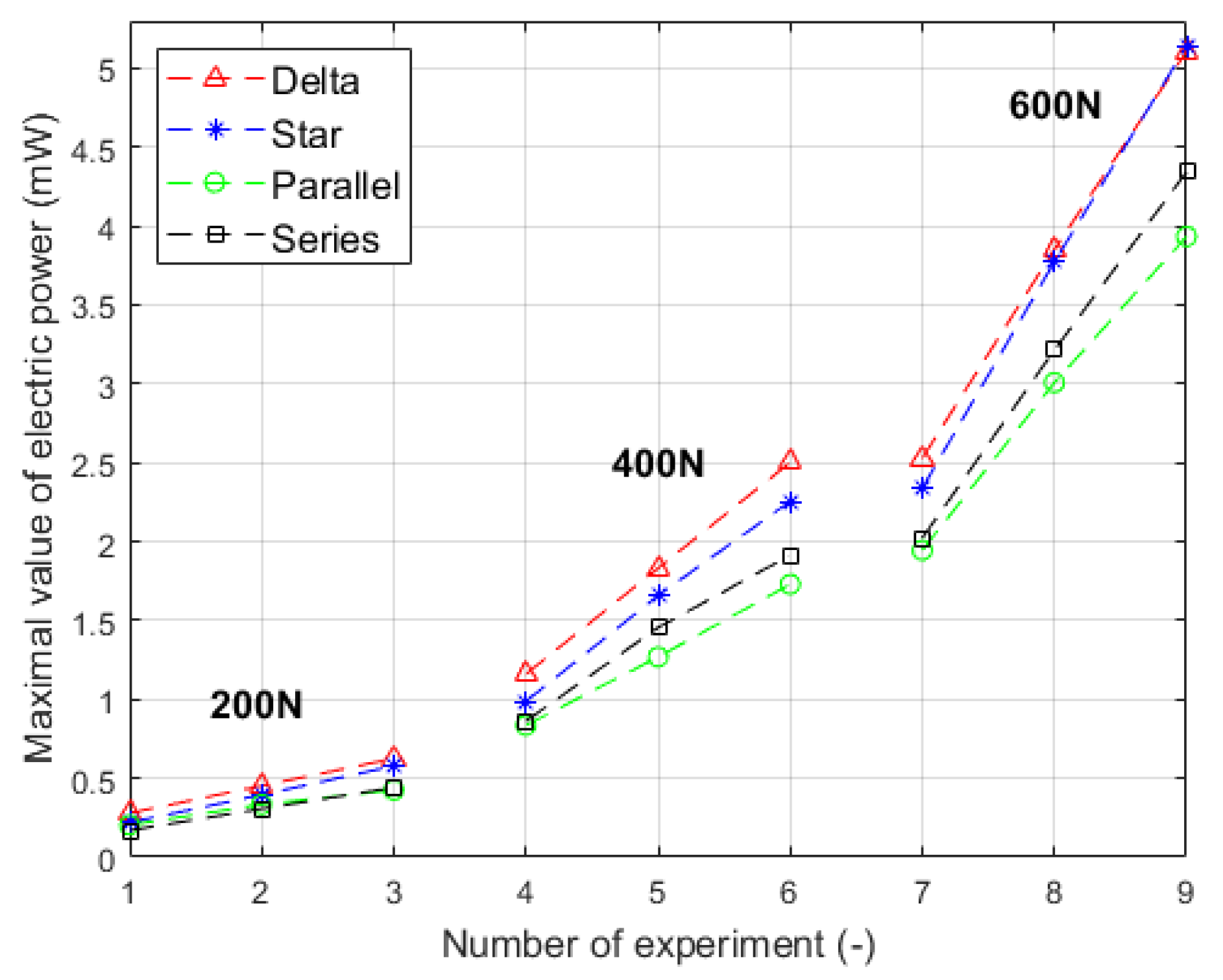
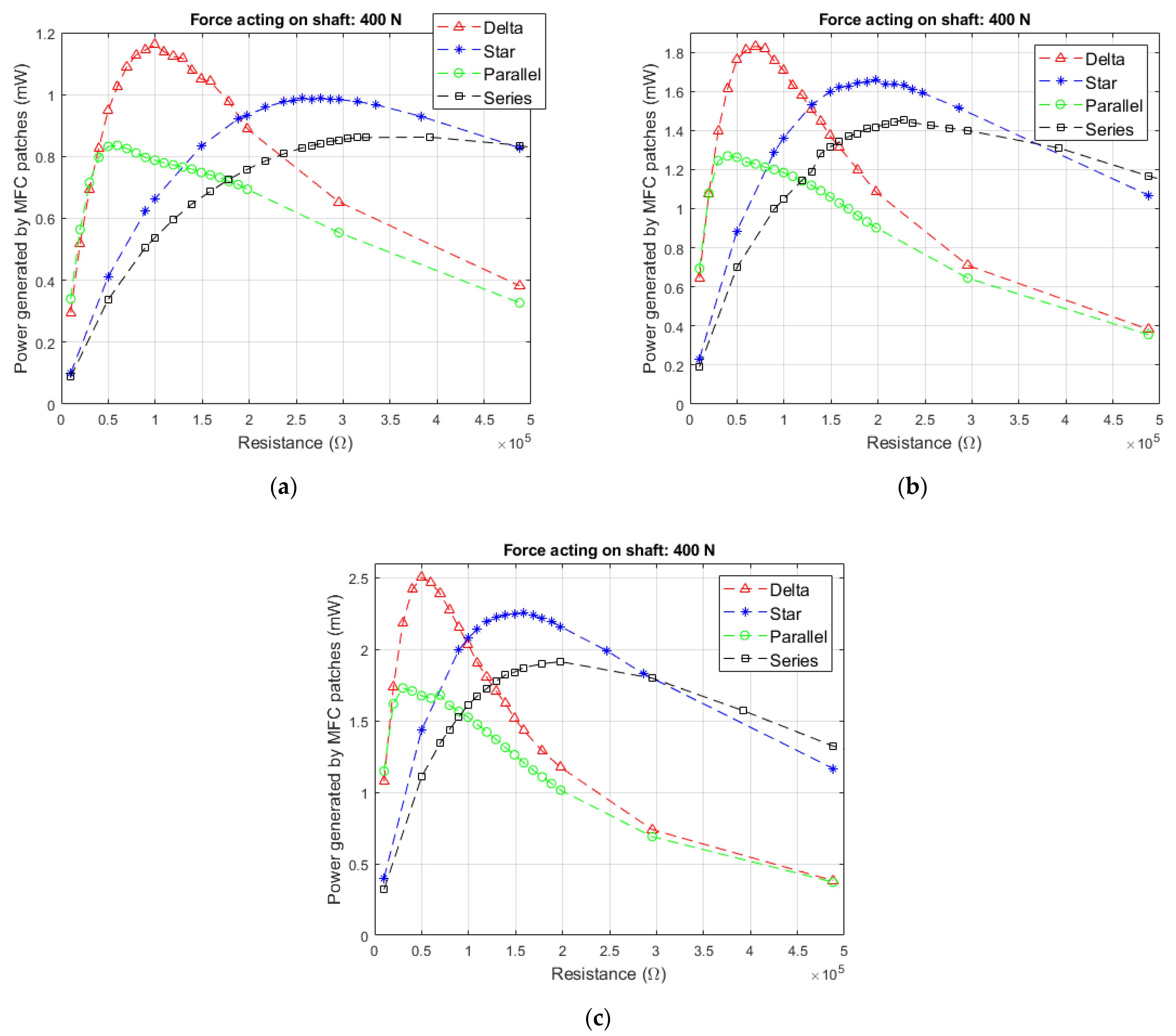
3.4. Electric Power Generated by MFC Arrays
4. Discussion
5. Conclusions
Author Contributions
Funding
Institutional Review Board Statement
Informed Consent Statement
Data Availability Statement
Conflicts of Interest
References
- Wang, Z.; He, L.; Gu, X.; Yang, S.; Wang, S.; Wang, P.; Cheng, G. Rotational energy harvesting systems using piezoelectric materials: A review. Rev. Sci. Instrum. 2021, 92, 041501. [Google Scholar] [CrossRef]
- Machado, S.P.; Febbo, M.; Ramírez, J.M.; Gatti, C.D. Rotational double-beam piezoelectric energy harvester impacting against a stop. J. Sound Vib. 2020, 469, 115141. [Google Scholar] [CrossRef]
- Guan, M.; Liao, W.H. Design and analysis of a piezoelectric energy harvester for rotational motion system. Energy Convers. Manag. 2016, 111, 239–244. [Google Scholar] [CrossRef]
- Kim, G.W. Piezoelectric energy harvesting from torsional vibration in internal combustion engines. Int. J. Automot. Technol. 2015, 16, 645–651. [Google Scholar] [CrossRef]
- Yan, L.; Hou, J.; Yang, Z.; Chu, X. Design and experimental characterization of a vibration energy harvesting device for rotational systems. Adv. Mech. Eng. 2013, 5, 263614. [Google Scholar] [CrossRef]
- Cheng, C.; Chen, Z.; Xiong, Y.; Shi, H.; Yang, Y. A high-efficiency, self-powered nonlinear interface circuit for bi-stable rotating piezoelectric vibration energy harvesting with nonlinear magnetic force. Int. J. Appl. Electromagn. Mech. 2016, 51, 235–248. [Google Scholar] [CrossRef] [Green Version]
- Grzybek, D.; Micek, P. Piezoelectric energy harvesting based on macro fiber composite from a rotating shaft. Phys. Scr. 2019, 94, 095802. [Google Scholar] [CrossRef]
- Roundy, S.; Tola, J. Energy harvester for rotating environments using offset pendulum and nonlinear dynamics. Smart Mater. Struct. 2014, 23, 105004. [Google Scholar] [CrossRef] [Green Version]
- Yang, B.; Yi, Z.; Tang, G.; Liu, J. A gullwing-structured piezoelectric rotational energy harvester for low frequency energy scavenging. Appl. Phys. Lett. 2019, 115, 063901. [Google Scholar] [CrossRef]
- Zhao, L.C.; Zou, H.X.; Yan, G.; Liu, F.R.; Tan, T.; Zhang, W.M.; Peng, Z.K.; Meng, G. A water-proof magnetically coupled piezoelectric-electromagnetic hybrid wind energy harvester. Appl. Energy 2019, 239, 735–746. [Google Scholar] [CrossRef]
- Zhang, J.; Fang, Z.; Shu, C.; Zhang, J.; Zhang, Q.; Li, C. A rotational piezoelectric energy harvester for efficient wind energy harvesting. Sens. Actuators A Phys. 2017, 262, 123–129. [Google Scholar] [CrossRef]
- Kurt, E.; Cottone, F.; Uzun, Y.; Orfei, F.; Mattarelli, M.; Özhan, D. Design and implementation of a new contactless triple piezoelectrics wind energy harvester. Int. J. Hydrogen Energy 2017, 42, 17813–17822. [Google Scholar] [CrossRef]
- Bouzelata, Y.; Kurt, E.; Uzun, Y.; Chenni, R. Mitigation of high harmonicity and design of a battery charger for a new piezoelectric wind energy harvester. Sens. Actuators A Phys. 2018, 273, 72–83. [Google Scholar] [CrossRef]
- Zhao, L.C.; Zou, H.X.; Yan, G.; Liu, F.R.; Tan, T.; Wei, K.X.; Zhang, W.M. Magnetic coupling and flextensional amplification mechanisms for high-robustness ambient wind energy harvesting. Energy Convers. Manag. 2019, 201, 112166. [Google Scholar] [CrossRef]
- Bai, F.; Song, G.; Dong, W.; Guan, L.; Bao, H. Fan-structure wind energy harvester using circular array of polyvinylidene fluoride cantilevers. J. Intell. Mater. Syst. Struct. 2017, 28, 653–662. [Google Scholar] [CrossRef]
- Khameneifar, F.; Arzanpour, S.; Moallem, M. A piezoelectric energy harvester for rotary motion applications: Design and experiments. IEEE ASME Trans. Mechatron. 2012, 18, 1527–1534. [Google Scholar] [CrossRef]
- Na, Y.; Lee, M.S.; Lee, J.W.; Jeong, Y.H. Wind energy harvesting from a magnetically coupled piezoelectric bimorph cantilever array based on a dynamic magneto-piezo-elastic structure. Appl. Energy 2020, 264, 114710. [Google Scholar] [CrossRef]
- Ramezanpour, R.; Nahvi, H.; Ziaei-Rad, S. A vibration-based energy harvester suitable for low-frequency, high-amplitude environments: Theoretical and experimental investigations. J. Intell. Mater. Syst. Struct. 2016, 27, 642–665. [Google Scholar] [CrossRef]
- Kuang, Y.; Yang, Z.; Zhu, M. Design and characterisation of a piezoelectric knee-joint energy harvester with frequency up-conversion through magnetic plucking. Smart Mater. Struct. 2016, 25, 085029. [Google Scholar] [CrossRef]
- Fang, S.; Fu, X.; Du, X.; Liao, W.H. A music-box-like extended rotational plucking energy harvester with multiple piezoelectric cantilevers. Appl. Phys. Lett. 2019, 114, 233902. [Google Scholar] [CrossRef]
- Priya, S. Modeling of electric energy harvesting using piezoelectric windmill. Appl. Phys. Lett. 2005, 87, 184101. [Google Scholar] [CrossRef]
- Yang, Y.; Shen, Q.; Jin, J.; Wang, Y.; Qian, W.; Yuan, D. Rotational piezoelectric wind energy harvesting using impact-induced resonance. Appl. Phys. Lett. 2014, 105, 053901. [Google Scholar] [CrossRef]
- Micek, P.; Grzybek, D. Wireless stress sensor based on piezoelectric energy harvesting for a rotating shaft. Sens. Actuators A Phys. 2020, 301, 111744. [Google Scholar] [CrossRef]
- Zhang, S.Q.; Li, Y.X.; Schmidt, R. Modeling and simulation of macro-fiber composite layered smart structures. Compos. Struct. 2015, 126, 89–100. [Google Scholar] [CrossRef]
- Smart Material—Home of the MFC. Available online: https://www.smart-material.com/MFC-product-mainV2.html (accessed on 5 March 2021).
- Deraemaeker, A.; Nasser, H.; Benjeddou, A.; Preumont, A. Mixing rules for the piezoelectric properties of macro fiber composites. J. Intell. Mater. Syst. Struct. 2009, 20, 1475–1482. [Google Scholar] [CrossRef] [Green Version]
- Syta, A.; Bowen, C.R.; Kim, H.A.; Rysak, A.; Litak, G. Experimental analysis of the dynamical response of energy harvesting devices based on bistable laminated plates. Meccanica 2015, 50, 1961–1970. [Google Scholar] [CrossRef] [Green Version]
- Shi, Y.; Hallett, S.R.; Zhu, M. Energy harvesting behaviour for aircraft composites structures using macro-fibre composite: Part I–Integration and experiment. Compos. Struct. 2017, 160, 1279–1286. [Google Scholar] [CrossRef] [Green Version]
- Song, H.J.; Choi, Y.T.; Wereley, N.M.; Purekar, A.S. Energy harvesting devices using macro-fiber composite materials. J. Intell. Mater. Syst. Struct. 2010, 21, 647–658. [Google Scholar] [CrossRef]
- Liao, Y.; Sodano, H.A. Modeling and comparison of bimorph power harvesters with piezoelectric elements connected in parallel and series. J. Intell. Mater. Syst. Struct. 2010, 21, 149–159. [Google Scholar] [CrossRef]


| Parameter | Symbol | Unit | Value |
|---|---|---|---|
| External diameter of shaft | Dso | mm | 40 |
| Internal diameter of shaft | Dsi | mm | 36 |
| Young’s modulus of steel | Ys | Pa | 205 × 109 |
| Distance between bearing A and center of shaft | 11 | mm | 310 |
| Distance between bearing B and center of shaft | 12 | mm | 310 |
| Parameter | Symbol | Unit | Value |
|---|---|---|---|
| Length of piezoelectric area inside MFC patch | lp | mm | 85 |
| Overall length of MFC patch | lMFC | mm | 100 |
| Width of piezoelectric area in MFC patch | wp | mm | 14 |
| Thickness of MFC patch | tMFC | mm | 0.3 |
| Thickness of piezoelectric fiber inside MFC patch | tpf | mm | 0.18 |
| Piezoelectric constant of piezoelectric fibers | d31 | C/N | −185 × 10−12 |
| Relative permittivity of piezoelectric fibers | - | 1850 | |
| Young modulus of piezoelectric fibers | Yp | Pa | 54.05 × 10⁹ |
| Number of Experiment | |||||||||||
|---|---|---|---|---|---|---|---|---|---|---|---|
| 1 | 2 | 3 | 4 | 5 | 6 | 7 | 8 | 9 | |||
| Parameter | Symbol | Unit | Value of Parameter in Experiment | ||||||||
| Force acting on shaft | Fb | N | 200 | 200 | 200 | 400 | 400 | 400 | 600 | 600 | 600 |
| Rotational speed of shaft | n | rps | 10 | 15 | 20 | 10 | 15 | 20 | 10 | 15 | 20 |
| Array | Number of Experiment | ||||||||
|---|---|---|---|---|---|---|---|---|---|
| 1 | 2 | 3 | 4 | 5 | 6 | 7 | 8 | 9 | |
| Maximal Values of Electric Power (mW) | |||||||||
| Delta circuit | 0.2795 | 0.4527 | 0.6256 | 1.1605 | 1.8306 | 2.5025 | 2.5287 | 3.8522 | 5.1072 |
| Star circuit | 0.2195 | 0.3956 | 0.5778 | 0.9874 | 1.6578 | 2.2553 | 2.3389 | 3.7737 | 5.1396 |
| Parallel connection | 0.2040 | 0.3342 | 0.4256 | 0.8357 | 1.2690 | 1.7297 | 1.9454 | 3.0079 | 3.9341 |
| Series connection | 0.1695 | 0.3073 | 0.4406 | 0.8625 | 1.4552 | 1.9134 | 2.0221 | 3.2148 | 4.3432 |
| Array | Number of Experiment | ||||||||
|---|---|---|---|---|---|---|---|---|---|
| 1 | 2 | 3 | 4 | 5 | 6 | 7 | 8 | 9 | |
| Optimal Load Resistance (kΩ) | |||||||||
| Delta circuit | 99.5 | 59.8 | 49.8 | 99.5 | 69.7 | 49.8 | 89.5 | 69.7 | 49.8 |
| Star circuit | 276.1 | 198.0 | 148.8 | 276.1 | 198.0 | 158.7 | 266.4 | 188.2 | 148.8 |
| Parallel connection | 59.8 | 39.9 | 29.9 | 59.8 | 39.9 | 29.9 | 49.8 | 39.9 | 29.9 |
| Series connection | 314.9 | 237.1 | 178.3 | 392.1 | 227.3 | 198.0 | 392.1 | 276.1 | 198.0 |
| Array | Number of Experiment | ||||||||
|---|---|---|---|---|---|---|---|---|---|
| 1 | 2 | 3 | 4 | 5 | 6 | 7 | 8 | 9 | |
| Maximal Values of Current (mA) | |||||||||
| Delta circuit | 0.085 | 0.126 | 0.164 | 0.172 | 0.254 | 0.328 | 0.261 | 0.373 | 0.481 |
| Star circuit | 0.047 | 0.075 | 0.103 | 0.100 | 0.152 | 0.199 | 0.157 | 0.235 | 0.309 |
| Parallel connection | 0.091 | 0.134 | 0.167 | 0.184 | 0.263 | 0.339 | 0.286 | 0.404 | 0.516 |
| Series connection | 0.040 | 0.063 | 0.086 | 0.093 | 0.138 | 0.179 | 0.144 | 0.213 | 0.278 |
Publisher’s Note: MDPI stays neutral with regard to jurisdictional claims in published maps and institutional affiliations. |
© 2021 by the authors. Licensee MDPI, Basel, Switzerland. This article is an open access article distributed under the terms and conditions of the Creative Commons Attribution (CC BY) license (https://creativecommons.org/licenses/by/4.0/).
Share and Cite
Micek, P.; Grzybek, D. Experimental Analysis of the Arrays of Macro Fiber Composite Patches for Rotational Piezoelectric Energy Harvesting from a Shaft. Energies 2021, 14, 4815. https://doi.org/10.3390/en14164815
Micek P, Grzybek D. Experimental Analysis of the Arrays of Macro Fiber Composite Patches for Rotational Piezoelectric Energy Harvesting from a Shaft. Energies. 2021; 14(16):4815. https://doi.org/10.3390/en14164815
Chicago/Turabian StyleMicek, Piotr, and Dariusz Grzybek. 2021. "Experimental Analysis of the Arrays of Macro Fiber Composite Patches for Rotational Piezoelectric Energy Harvesting from a Shaft" Energies 14, no. 16: 4815. https://doi.org/10.3390/en14164815
APA StyleMicek, P., & Grzybek, D. (2021). Experimental Analysis of the Arrays of Macro Fiber Composite Patches for Rotational Piezoelectric Energy Harvesting from a Shaft. Energies, 14(16), 4815. https://doi.org/10.3390/en14164815