1. Introduction
At the initial stage of the power theory development, known since the beginning of the 20th century for sinusoidal AC networks, there were no contradictions in the formulations and calculated expressions [
1,
2]. Instead of instantaneous values of sinusoidal voltages
and currents
, for the convenience of analysis and calculations in the well-known symbolic method, it is proposed to use their effective values
and
. The product of these values
determines the total or apparent power
. The reactive nature of the network
elements explains the phase shift
between voltage
and current
. In this case, the apparent power
consists not only of active power
capable of performing work, but also of ballast reactive power
. The components
and
make up the power balance
, in which the proved orthogonality of
with respect to
[
1,
2] is emphasized.
However, the appearance of loads with nonlinear current–voltage characteristics (CVC) led to a significant distortion of the network currents’ curve shape and of supply voltages, which resulted in the formation of other inactive power components that do not perform useful work. It is obvious that the interaction of harmonics of non-sinusoidal voltage and current will create its own components of reactive power, etc. from each harmonic separately.
However, in this case, the excess of power
over power
can no longer be explained by the emergence of only reactive power
because of all harmonics. In the scientific literature [
3,
4], this circumstance is explained by the appearance of another component of inactive power, which is known as the power of
distortions. However, such view is not supported by all researchers and, to this day, it causes controversy about the correct definition of the combination of
and
, and their delineation taking into account higher harmonics.
For about 100 years, discussions have continued on the definition of the terminology for components
and
, their calculation, and the correct interpretation of their physical nature [
4,
5,
6,
7].
3. Aspects in the Development of Inactive Capacities Theories
In the historical aspect, the works of many scientists are devoted to the definition of inactive powers in non-sinusoidal AC networks. The work of Budeanu [
3] describes one of the first explanations of the mechanism of occurrence of the power imbalance, when the power is decomposed into orthogonal components
and
, and defining
as a set of reactive powers
caused by individual harmonics:
where
is the ordinal numbers of the harmonics of the effective values of voltages
and currents
;
is the shear angles between them. It is in this theory that the power balance is achieved by introducing an additional component of inactive power, mutually orthogonal with respect to the already known components and in such a way that:
The value
was presented as a measure of the mutual distortion of the curves
and
. However, it has already been noted in [
10] that, in AC networks with certain combinations of higher harmonics at the level of instantaneous powers, the interaction of the components
and
can occur and in such a way that
even in conditions of a distorted shape of the curve
relative to
. Vice versa,
provided that the shape of the curve
is similar to the shape of the curve
. This fact gave rise to doubts about the validity of the Budeanu theory and the search for other approaches to determining the inactive power that do not contradict the results of the experiments.
Such approaches were available in early works by Fryze [
2,
10,
11]. In them, inactive power
is not divided into components
and
or the like, but it is defined as a power imbalance:
Since, by definition, cannot do the job, the Fryze theory is built on dividing the instantaneous load currents into two components: active and reactive currents, in such a way that . Assuming that the currents’ components and are mutually orthogonal, their respective effective values and will define the initial current as .
Hence, there is no explicit physical interpretation for power in the representation of the Fryze theory, as it has been done for sinusoidal circuits.
Subsequent works [
12,
13], in which the development of the theory of powers is based on frequency techniques, are devoted to the establishment of the relationship between the higher harmonics of voltage and current with the components of inactive powers. This defines reduced power, and, using the ratios of the frequencies of the fundamental and higher harmonics with ordinal numbers
, the following determination of inactive power
has been obtained:
However, it, like many other similar calculated expressions in practice, had not always provided a power balance [
10,
14] in an AC network with a non-sinusoidal shape
and
.
In subsequent works [
15], an attempt was made to further divide the current
into orthogonal components: inactive current and a residual component. The inactive current determines the parameter of the passive reactive element (inductance or capacitance). For the harmonics with ordinal numbers
, this approach provides an expression for determining
:
The value in these works was obtained as a result of reducing the reactive nature of the network elements, and, from a practical point of view, it allows for determining the parameters of the compensation device for the inactive current component using passive elements. However, the origin and physical meaning of the residual component of the inactive current are not considered.
The component of current
, according to the Fryze theory, was determined in subsequent works by Czarnecki [
7,
16] in accordance with expression (1) and the development of the provisions of the CPT (Conservative Power Theory). The inactive part was analyzed from the point of view of frequency calculation methods according to the CPC (Currents Physical Components) theory that are also using the methodology of orthogonal decomposition [
17]. In this representation, reactive power is defined as the result of a large number of orthogonal components of currents
of different frequencies and is calculated as:
The total power of a linear load supplied from an AC network with a non-sinusoidal
, in accordance with this theory, is
. The component
has been named as the dissipated power generated by the current components depending on the frequency spectrum
. Therefore, only the component
can be compensated by means of passive elements [
7]. If the load turns out to be nonlinear, then this theory allows one to single out another component of the current
, the harmonics of which are not determined by the spectrum of the periodic function, but are independently generated by the nature of the load itself [
16], forming the corresponding power component
. In this case, the total power in a single-phase network will be determined by the combination of already four components
.
Thus, in studies using frequency, spectral, and similar calculation methods based on the concepts of effective values of voltages and currents, no unity was found in the quantitative determination of the components of inactive powers and their physical interpretation.
In order to exclude possible errors in determining the power components, made in the course of intermediate calculations based on instantaneous values
and
, neither frequency nor spectral, but integral techniques were used in the works of individual researchers, which do not require finding the effective values of harmonics. Thus, in the methods [
13,
18], the nature of the load is determined through its I–V characteristic. For this purpose, the area of the closed figure of the I–V characteristic of the load in the axes
and
for the period
has been determined by integration as a value [
19] that is proportional to the power
:
A similar approach is described in [
13], where the value
was obtained in the course of the cyclic integration operation:
It is easy to see that expressions (2)–(8) not only characterize the components of inactive capacities in different ways, but, in the case of calculations, they will lead to a significant discrepancy between the obtained results.
Therefore, in recent years, in the theory of inactive powers, the tendency of direct analysis of instantaneous values has dominated, which has become the basis of the theory of instantaneous powers. The advantage of the theory of instantaneous powers is the elimination of intermediate concepts and calculations, which, when applied to nonlinear and non-sinusoidal AC circuits, can lead to fundamental errors in definitions and calculations due to an incorrect interpretation of the physical nature of the emergence of individual power components.
The concept of considering the instantaneous values of voltages and currents, applied in the first works of Fryze [
2,
11], was later used in [
20] as the FBD theory (Fryze, Buchholtz, Depenbrock), described in more detail in [
21,
22]. The theory of instantaneous powers was further developed in the concept of the pq-theory [
23], which determines the instantaneous values of active
and reactive
power through combinations of the products of the values of projections
and
onto orthogonal axes. The consequence of the development of the theory of instantaneous powers was its generalization in the cross-vector theory [
17,
24], in which the value
is defined as the scalar product of vectors
and
, and the value
is defined as their vector product.
It should be noted that the provisions of individual theories of inactive power are capable of solving a number of practical problems with some success, for example, analyzing the operating modes of electrical networks or designing technical means to compensate for reactive power [
25]. However, until now, none of the presented theories have yielded an unambiguous physical interpretation or explanation of the physical meanings of all the components of inactive powers, their occurrence, and interaction for arbitrary shapes of curves
and
.
This hinders the development of effective calculation methods and the adoption of relevant standards, in which, first of all, there would be a clear, relatively simple, and unambiguous definition of the process of occurrence of each power component for the subsequent calculation of the total inactive power in electrical networks in which non-sinusoidal voltages and currents operate. This is evidenced by the IEEE 1459–2010 Standard adopted at due time [
26], in which the concept of inactive power is introduced, but the definition of power
is limited only by the first harmonic.
4. Analysis of Inactive Power Components in Wave and Vector Diagrams
If voltage and current harmonics, for example, the first harmonics
, with the same ordinal numbers interact in the AC network, then, from the point of view of the symbolic method [
1], the current vector
can either lag behind or ahead of the supply voltage vector
by an angle
. Characterizing these values as
and
, the instantaneous load power
is conventionally divided into a constant component
and an alternating component
:
The integral sum of the components
and
for the period
corresponding to the full reversal of the vectors
and
is capable of forming active power
, being determined by the argument
as
, or proceeding to the effective values
,
:
In this connection, , . The appearance of an alternating value in the combination of components and over a period characterizes the action of exchange or reactive power between the elements of the AC network, for example, a source and a load. As it follows from expression (9), the sign will change at a frequency of twice over the period .
The quantity
can be traditionally expressed through the unbalance of total power
and active power
, using the well-known property of orthogonality of the components
and
as in the case of
, which gives the well-known expression [
1,
3]:
As the vector lags behind the vector , the component decreases, and negative values appear and grow, which indicates a decrease in the component and the appearance of a growing component .
If the harmonics of voltage
and current
, having different ordinal numbers
, interact in an AC network, then, due to the orthogonality property [
27] of these harmonics with multiple frequencies
during the working period
, the work cannot be done, since, in this case, the power is:
It makes no sense to further decompose such power into components and . However, as it follows from expression (3), the total power in this case will be a value that is commonly called the distortion power .
In this way, in an alternating current network, even with a sinusoidal voltage source, a load with a purely active character is capable of generating powers and , if it has a nonlinear I–V characteristic.
It is common knowledge that, if an artificial delay occurs in the opening of an electronic key in a single-phase AC network supplying a purely active load, a spectrum of higher current harmonics will form [
5,
6,
7]. In this spectrum, only the first harmonic of the current will create a component
.
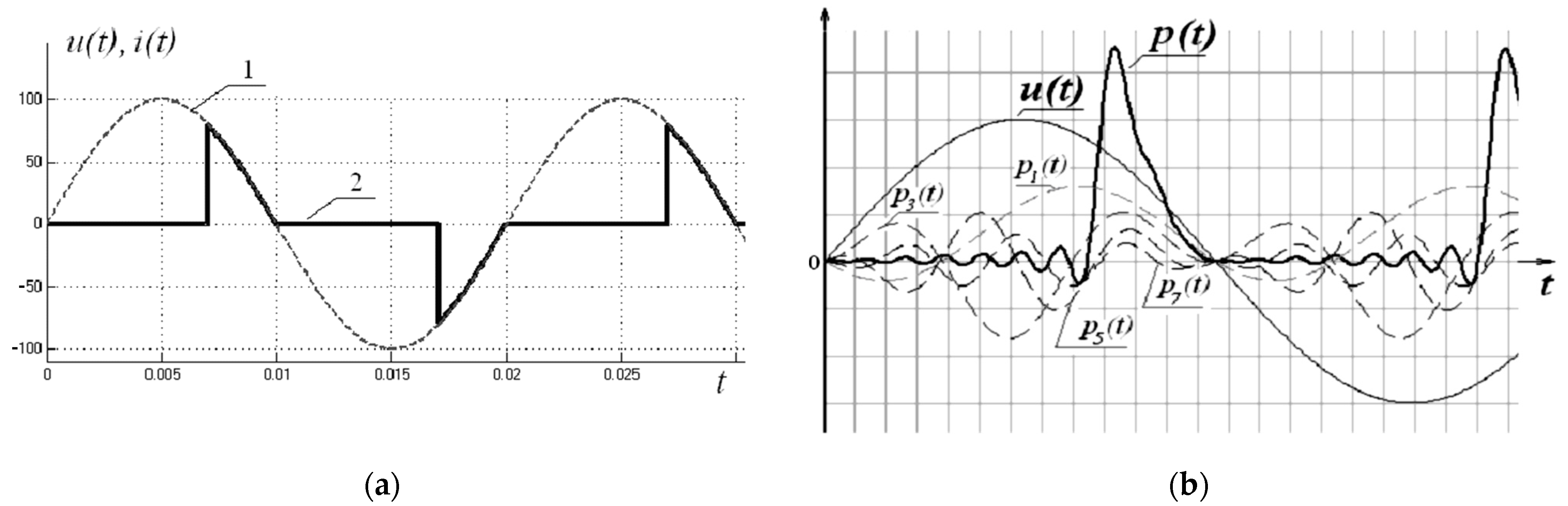
As an example,
Figure 1 shows oscillograms and the spectral composition (
Table 1) of the load current with
p.u. in a network with a sinusoidal voltage source of
p.u. and the frequency of
when the delay in the opening of the electronic keys was about 70% or 0.007 s.
In such network with a sinusoidal voltage of the power supply, a load with a purely active character causes a phase shift in the fundamental current harmonic of −54.8°, as if the load electrical circuit contained an inductive element, the reactive power of which can be formally calculated by expression (11). However, it is, of course, erroneous to assume that such circuits contain reactive elements that exchange power with a power source. Moreover, in separate works [
15,
17], it was noted that the concept of reactive power, which “characterizes the energy pumped from the source to the reactive elements of the receiver and then returned by these elements back to the source during the same period of oscillation, referred to this period”, does not fully reflect the physical meaning.
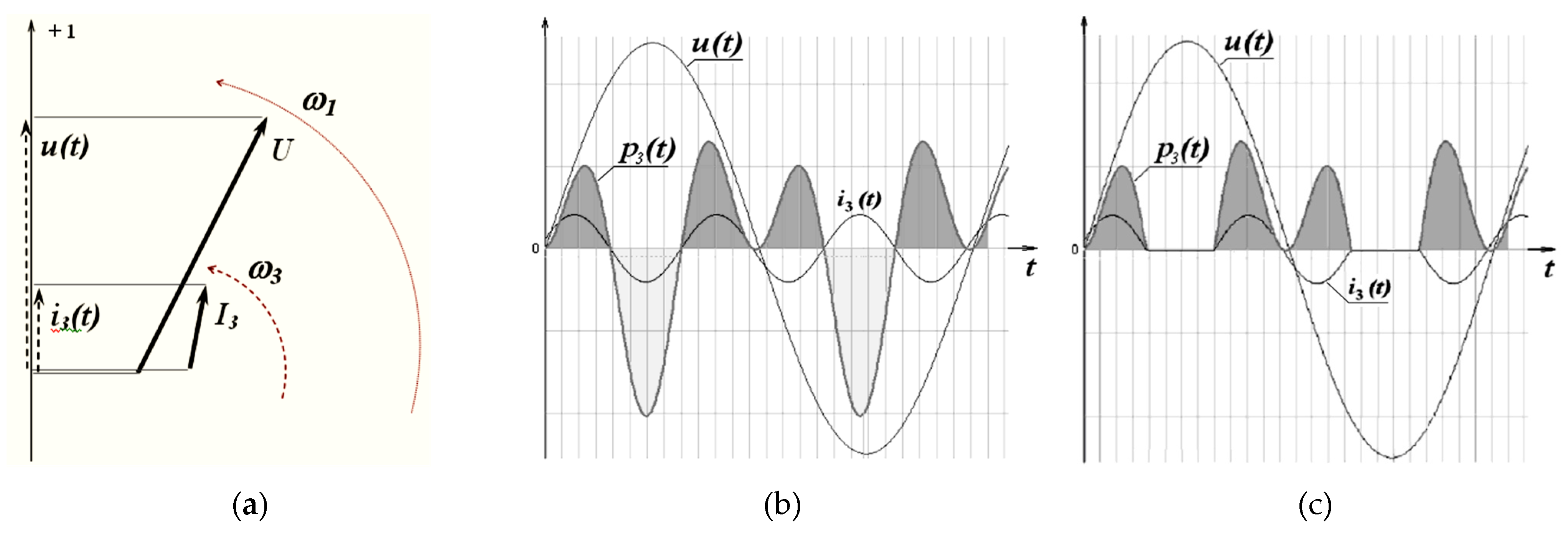
If the action of each harmonic (
Table 1) is analyzed separately in this example, then it is not too difficult to see in
Figure 2a that the vector of the current third harmonic
, built according to the data in
Table 1, is three times ahead of the voltage vector per one period
. The interaction of vectors
and
will create instantaneous power
, the alternating pulsations of which (
Figure 2b), due to the properties of expression (12), are distributed in such a way that the total area bounded by the curve
with positive values is equal to the total area bounded by this curve with negative values so that
. At the same time, the total power in this case is
V∙A. In
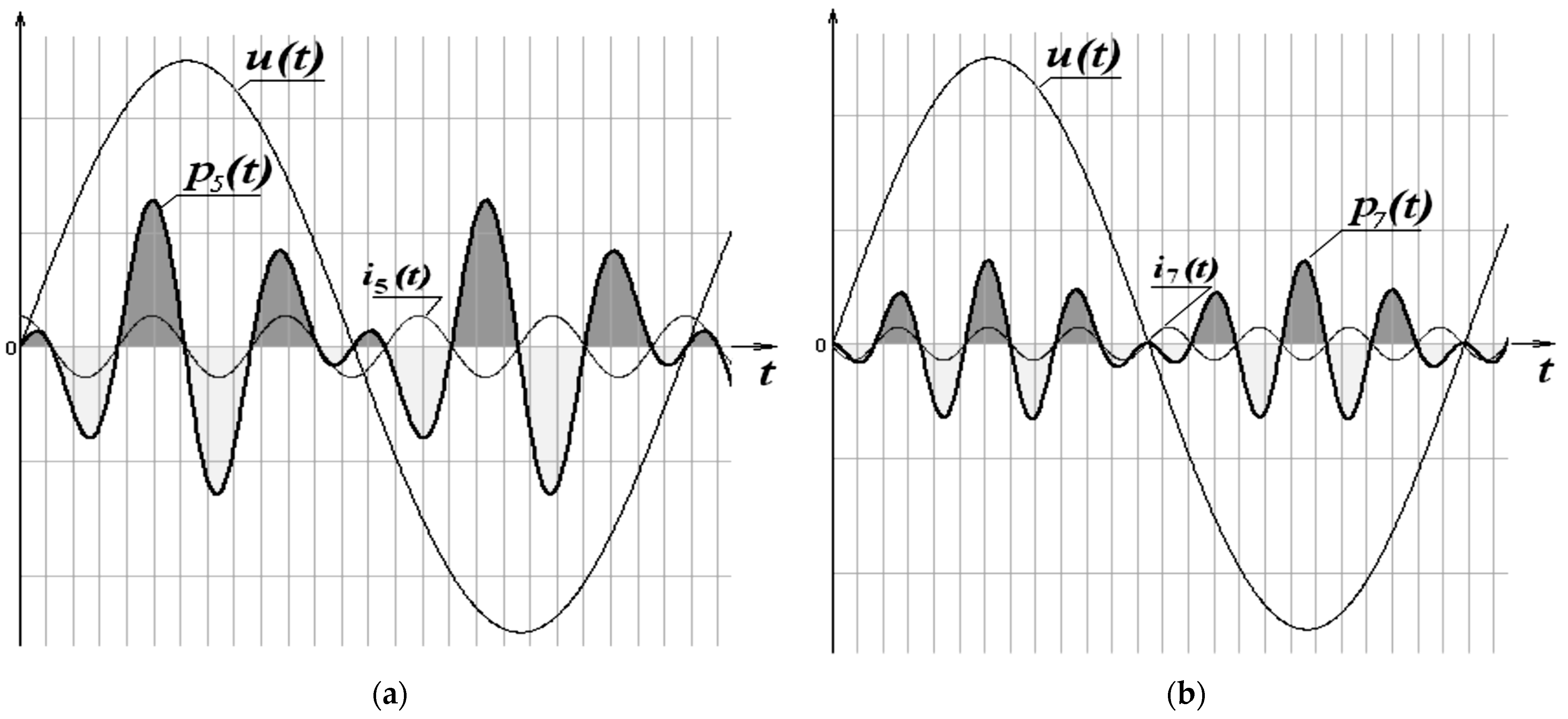
Figure 3 waveforms explaining the power generation for the fifth (
Figure 3a) and seventh (
Figure 3b) harmonics are shown. The remaining higher harmonics of current interacts with voltage
in a similar way; this is accompanied by the appearance of powers
,
V∙A,
,
V∙A.
Thus, the actions of the instantaneous values of the components of
, taking into account all higher harmonics, are completely mutually neutralized in the time intervals when the electronic switch is open (
Figure 1b). This example shows that the power
from the first harmonic of the current is not the prerogative of the manifestation of the properties of reactive elements in the AC network, but it can be considered as an imbalance of instantaneous values
that have caused a shift in the components
and
.
In fact, power
interacts with power components
at the level of redistribution of instantaneous values
, while the values of the components
and
remain unchanged [
28]. This is due to the fact that one harmonic, characterizing a certain power component, as follows from the properties of the Fourier series [
27], cannot be obtained or compensated for by a set of other harmonics. In this case, it is possible to correct the shape of the curve
of an arbitrary AC consumer by regulating the phase shifts of the quantities
created, for example, in accordance with expression (12) using an inactive power compensator with zero active power [
29,
30,
31].
The set of values with orthogonal properties of harmonics is written as:
In this example, there is only one voltage harmonic
; therefore,
. According to
Table 1, this value is
V∙A.
Active and reactive powers calculated using
Table 1 by expressions (10) and (11) have the following values:
This provides the power balance according to expression (2), since:
This yields or .
This confirms the idea in the Budeanu theory [
3] that the powers
,
, and
are mutually orthogonal, and the difference
determines the totality of inactive powers
.
5. Analysis of Budeanu Theory Criticisms
Despite the fact that calculations similar to the above-mentioned example prove the consistency of the Budeanu’s theory [
3], a number of researchers, for example [
4,
9,
10,
32], pose a number of questions:
- (1)
Why, in practice, expression (2) is not true for all measured modes of operation of consumers in the alternating current network;
- (2)
Why distortion power can occur in conditions when the load current curve is similar to the supply voltage curve and vice versa; provided that the load current curve is clearly distorted relative to the supply voltage curve;
The answer to the first question is determined, first of all, by the reasons that violate the property of harmonics orthogonality (12). This is possible if the parameters of the higher harmonics of the current (amplitude, phase shift) are not stationary during the operating period
, which is quite typical of AC circuits containing modern semiconductor devices. This will lead to a violation of the equality of the areas bounded by the curves
for positive and negative values, as is shown in
Figure 2b. In such cases, individual current harmonics with non-stationary parameters, interacting with the mains voltage
, are able to do work because, for them,
.
For example, let us assume a simple condition that per one period:
one can obtain a pulsating, but positive power in
Figure 2c. It is not too difficult to see that, as a result of the accepted condition, a harmonic component
will appear in the spectral composition of the curve
shown in
Figure 2c, the lagging character of which will create an additional
V∙A component relatively
.
As a result, the active power calculated based on the first and highest harmonics will be:
reactive power:
distortion power:
full power:
Violation of the power balance or is just evidence of the incorrectness of calculating the effective values of the harmonics of currents or voltages under conditions of dynamic change in the parameters of the harmonic composition per one measurement period , when the higher harmonics did not have constancy in amplitudes and phase shifts.
In this way, the power components , , and must be methodically correctly calculated based on the instantaneous power values , which contain the most reliable information on the operating modes of the AC network.
To answer the second question, it is necessary to analyze the conditions for the appearance of —when the curves and are similar, and , when the curve is distorted relative to the curve .
The condition with the explicit presence of the spectral composition of the harmonics of the distorted curve relatively unambiguously indicates the compensation of the components in expression (13), which is possible in the case when each component .
Let, for example, the curves
and
form two harmonics of voltages
,
and currents
and
. In this case, the harmonics
and
form active powers according to expression (10):
They form reactive powers according to expression (11):
Proceeding from expression (2), the following can be obtained:
Hence, the distortion power can be expressed as:
Therefore:
if .
This is possible under the condition of simultaneous achievement of the identity in the ratios of rms values for all harmonics of voltages and currents:
and the equality of phase shifts in all harmonics of voltages and currents:
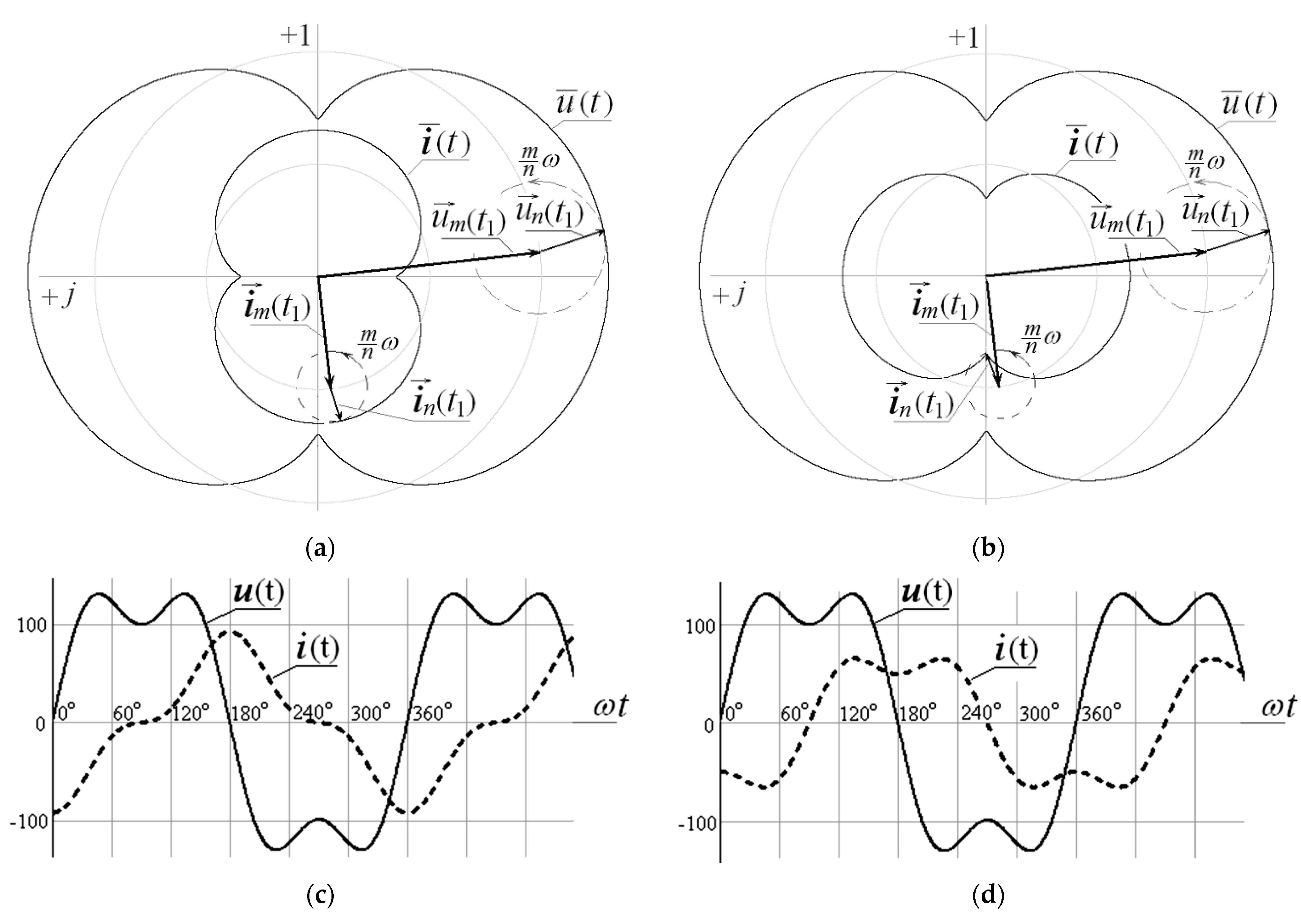
If the harmonics
,
,
,
that correspond to conditions (15) and (16) can be represented in the form of rotating vectors on the complex plane, then the projections of the resulting voltage
and current vectors
, unfolded in time, form (
Figure 4c) a distorted curve
with respect to the curve
. At the same time, the hodographs
and
of the resulting vectors are similar and mutually shifted by
(
Figure 4a). Along with this, the curves
and
characterize the formation of purely reactive power
in the AC network.
An attempt to provide the similarity of the curves
and
with formal preservation of the identity in their harmonic composition (
Figure 4b,d) leads to the fact that, in addition to reactive power
, distortion power
appears in the AC network, which is easily verified by numerical calculations using expressions (1)–(3), (10), (11), and (13).
In the case of a large number of harmonics in the AC network, expression (14) will take on a more cumbersome form [
28,
33]:
However, this does not fundamentally affect the behavior of the powers , , and in the AC network.
Thus, the power , despite its unsuccessful name, does not characterize the degree of distortion of the curve shape relative to , but it indicates the presence of such interactions of harmonics of currents and voltages with different ordinal numbers, which generate additional ballast powers that are not capable of performing useful work.


 ,
, 


