
Numerical Study on Damage Zones Induced by Excavation and Ventilation in a High-Temperature Tunnel at Depth


Abstract
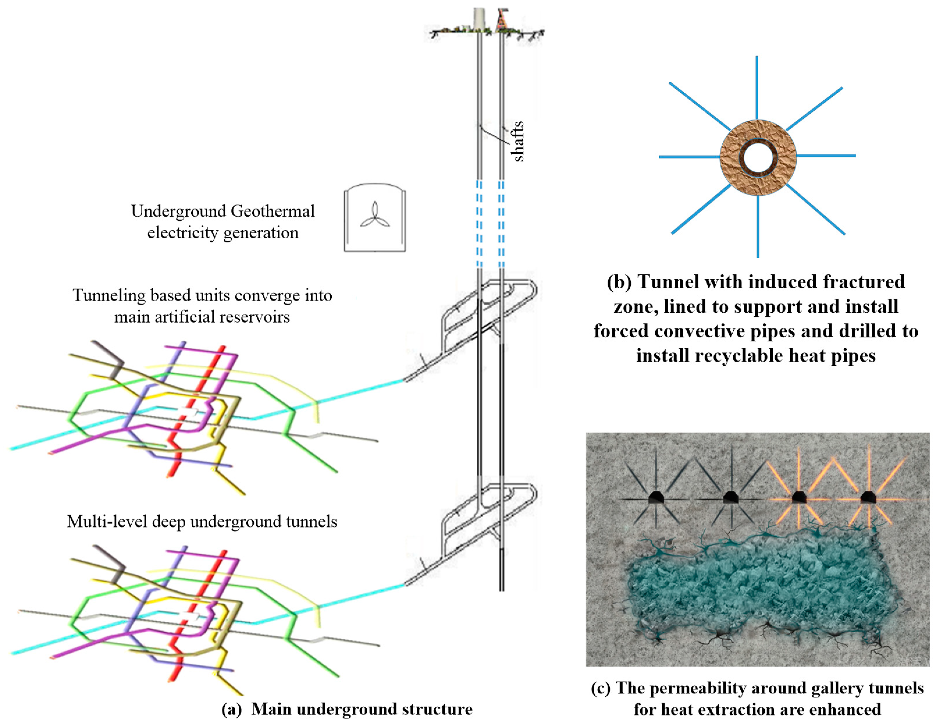
:1. Introduction
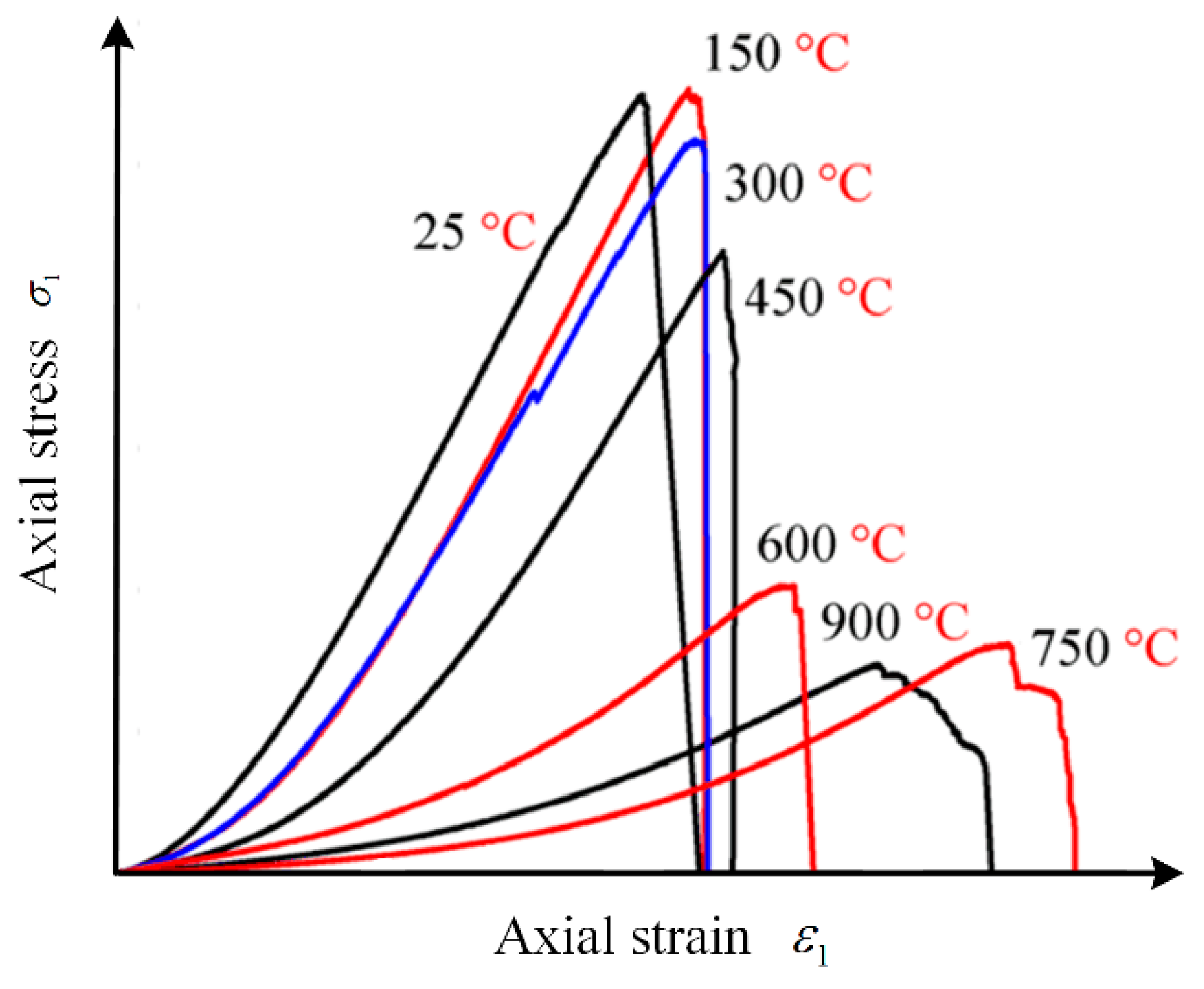
2. Influence of High Temperature on Granite Properties
3. Numerical Model to Study Tunneling Induced Excavation Damage Zone
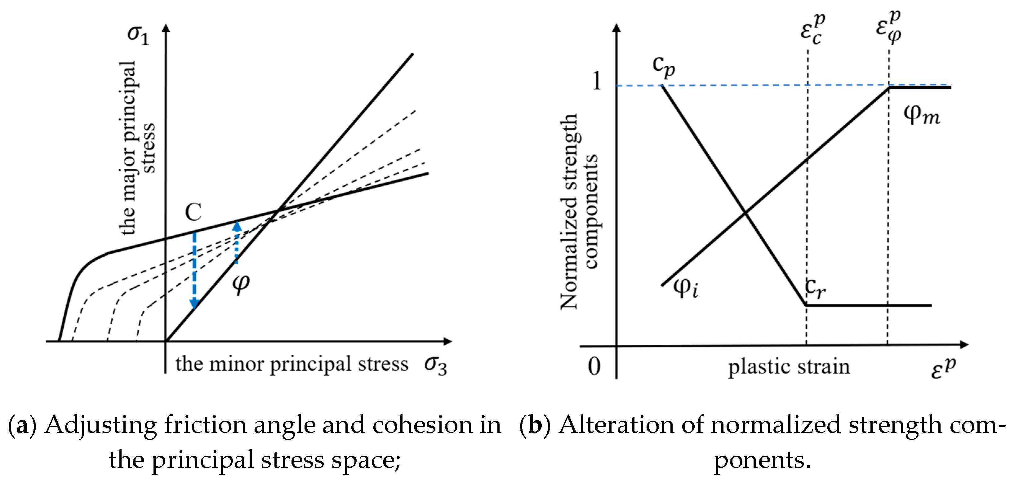
3.1. Damage Initiation–Spalling Limit (DISL) Criterion and CWFS Model
3.2. Numerical Modelling Simulator
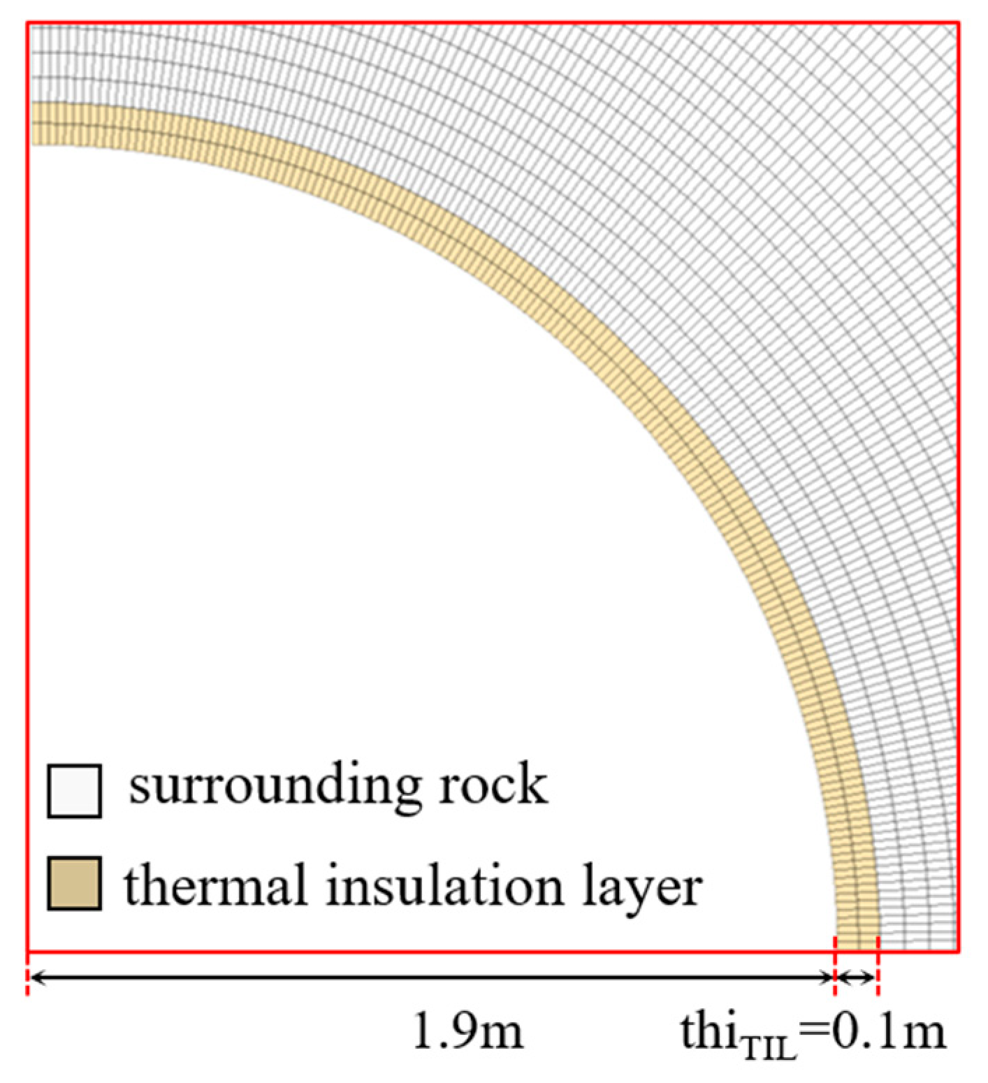
3.3. Model Geometry, Gridding, Initial and Boundary Conditions
3.4. Dependency of Material Mechanical Properties on Temperature Condition
4. Studying Tunneling Induced Excavation Damaged Zone (EDZ) in Depths
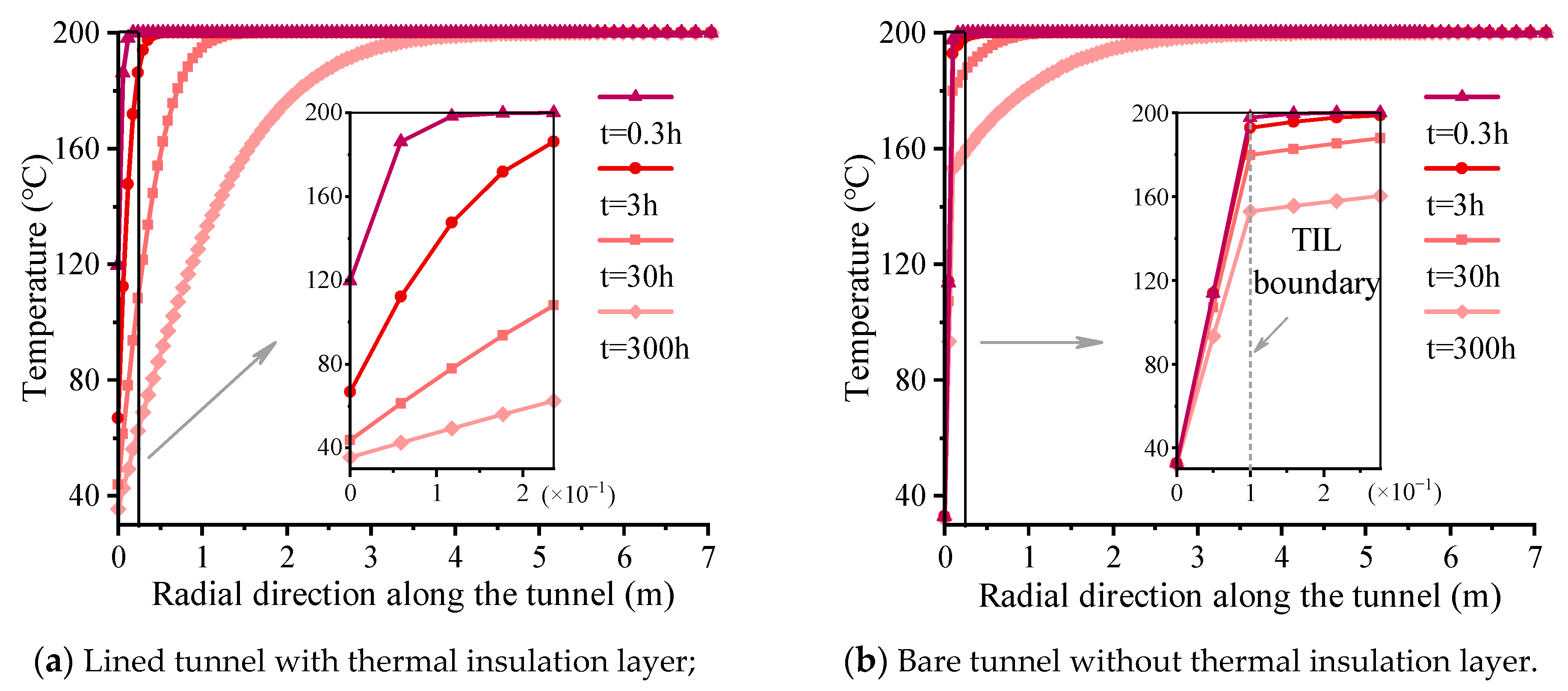
5. Temperature Distribution and Stress Field in EGS-E Tunnel after Ventilation Cooling
6. Conclusions
- (1)
- The CWFS model can well represent the progressive failure of surrounding rock from damage to complete loss of strength during unloading, and the initiation and propagation of EDZs. Small confinement at tunnel wall plays an important role in restraining failure.
- (2)
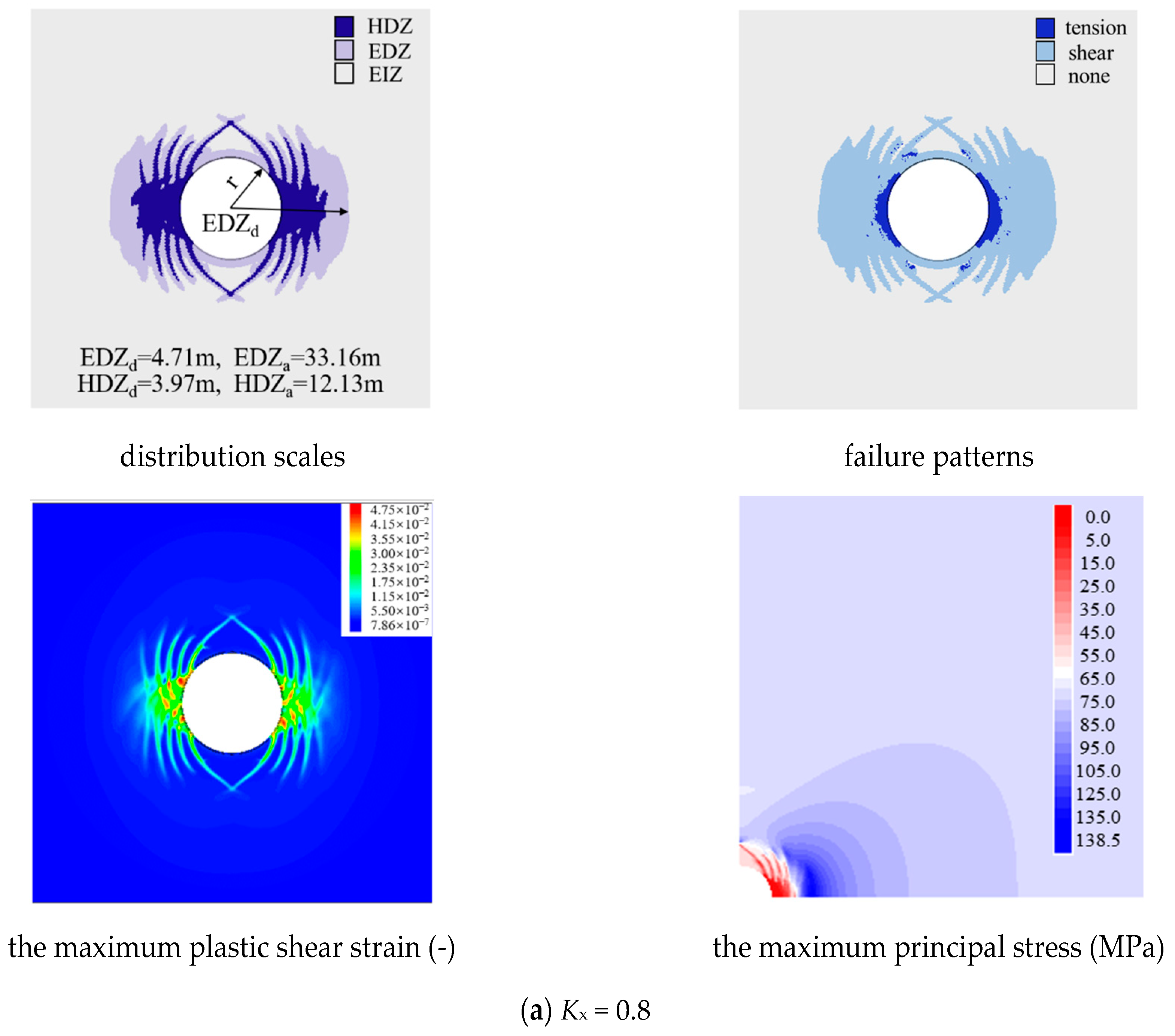
- When the tunnel is excavated under near hydrostatic pressure (Kx = 0.8, 1.0 and 1.2) in hard rock, shear fracture zone appears in all cases. Spalling failure occurs near the tunnel wall and the deep surrounding rock is controlled by shear fracture, which endan-ger the construction safety. Lateral pressure coefficients have a significant effect on the fracture morphology and scale of surrounding rock. When Kx = 0.8, 1.2, damage concentrates in the direction of the minimum principal stress, while the damage distribution is more uniform at Kx = 1.0, and when Kx = 1.0, 1.2, the EDZ scale is larger.
- (3)
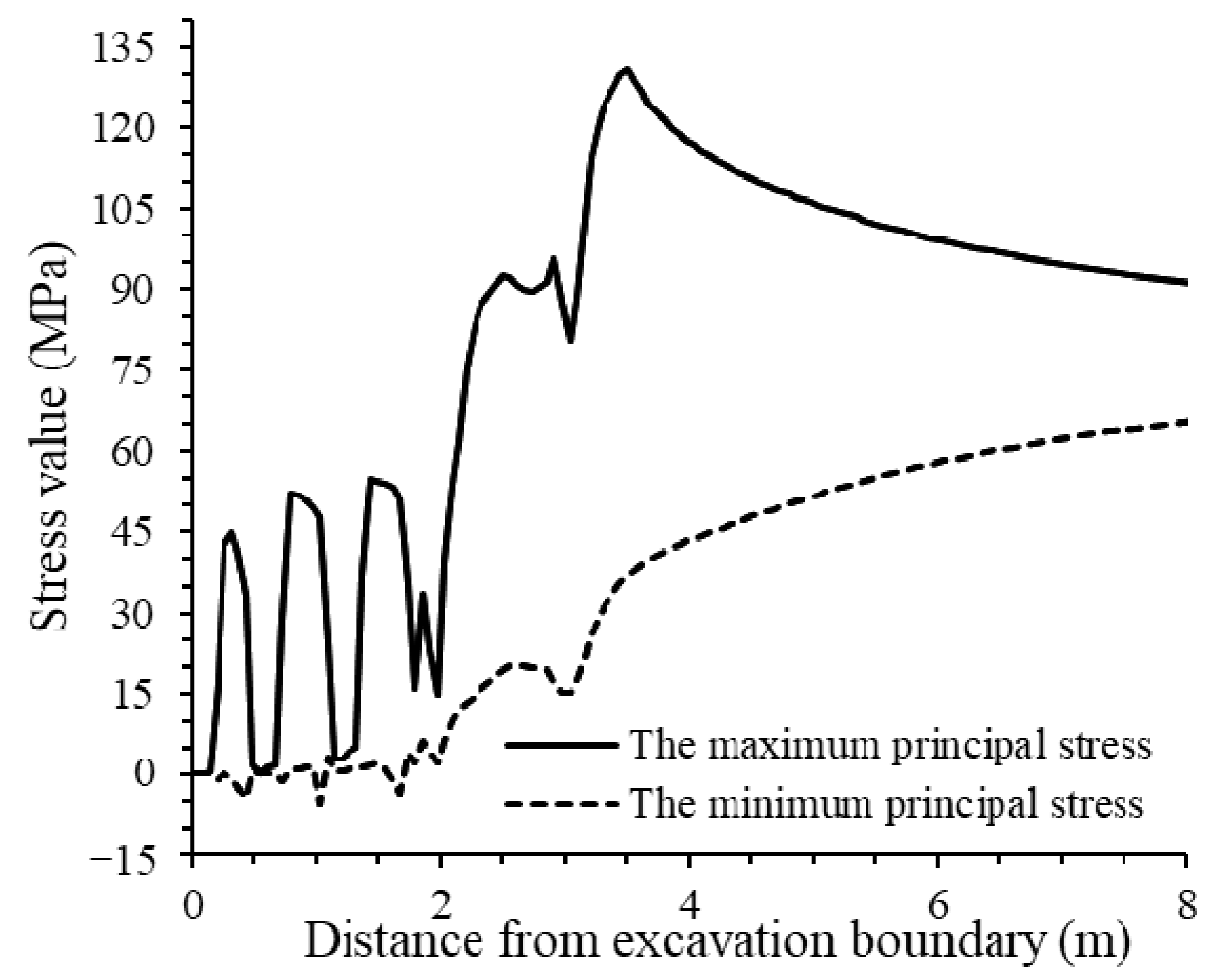
- Due to the ventilation, the surrounding rock stress significantly changes. Additional tensile stress is generated in the shallow part of the surrounding rock, and the maximum and minimum principal stresses decrease. The compressive stress concentration transfers to the deep, which promotes the further expansion of EDZs, and it experiences slow, rapid and deceleration stages with ventilation time. Therefore, the influence of rock cooling volume shrinkage on EDZs must be considered in a High-Temperature Tunnel. In addition, thermal insulation layer prolongs the slow growth stage.
Author Contributions
Funding
Institutional Review Board Statement
Informed Consent Statement
Data Availability Statement
Acknowledgments
Conflicts of Interest
Abbreviations
| EGS-E | Enhanced Geothermal System based on Excavation |
| CWFS | Cohesion-Weakening-Friction-Strengthening model |
| EDZs | Excavation Damaged Zones, including EDZ and HDZ |
| EDZ | Excavation Damage Zone |
| HDZ | Highly Damaged Zone |
| DISL | Damage Initiation–Spalling Limit |
| UCS | Uniaxial Compressive Strength |
| EDZa | the area of EDZ (m2) |
| EDZd | the depth of EDZ (m) |
| HDZa | the area of HDZ (m2) |
| HDZd | the depth of HDZ (m) |
References
- Xu, T.F.; Hu, Z.X.; Li, S.T.; Jiang, Z.; Hou, Z.; Li, F.; Feng, B. Enhanced Geothermal Systems: International progresses and research status of China. Acta Geol. Sin. 2018, 92, 1936–1947. (In Chinese) [Google Scholar]
- Lu, S. A global review of enhanced geothermal system (EGS). Renew. Sustain. Energy Rev. 2018, 81, 2902–2921. [Google Scholar] [CrossRef]
- Shortall, R.; Davidsdottir, B.; Axelsson, G. Geothermal energy for sustainable development: A review of sustainability impacts and assessment frameworks. Renew. Sustain. Energy Rev. 2015, 44, 391–406. [Google Scholar] [CrossRef]
- Lund, J.W.; Boyd, T.L. Direct utilization of geothermal energy 2015 worldwide review. Geothermics 2016, 60, 66–93. [Google Scholar] [CrossRef]
- Xu, T.; Zhang, Y.; Zeng, Z.; Bao, X. Technology progress in an Enhanced Geothermal System (Hot Dry Rock). Sci. Technol. Rev. 2012, 30, 42–45. (In Chinese) [Google Scholar]
- Ma, T.; Chen, P.; Zhao, J. Overview on vertical and directional drilling technologies for the exploration and exploitation of deep petroleum resources. Geomech. Geophys. Geo-Energy Geo-Resour. 2016, 2, 365–395. [Google Scholar] [CrossRef] [Green Version]
- Zhao, J.; Tang, C.A.; Wang, S.J. Excavation based enhanced geothermal system (EGS-E): Introduction to a new concept. Geomech. Geophys. Geo-Energy Geo-Resour. 2020, 6, 1–7. [Google Scholar] [CrossRef]
- Zang, A.; Stephansson, O.; Stenberg, L.; Plenkers, K.; Specht, S.; Milkereit, C.; Schill, E.; Kwiatek, G.; Dresen, G.; Zimmermann, G.; et al. Hydraulic fracture monitoring in hard rock at 410 m depth with an advanced fluid-injection protocol and extensive sensor array. Geophys. J. Int. 2016, 208, 790–813. [Google Scholar] [CrossRef]
- Kang, J.; Zhu, J.; Zhao, J. A review of mechanisms of induced earthquakes: From a view of rock mechanics. Geomech. Geophys. Geo-Energy Geo-Resour. 2019, 5, 171–196. [Google Scholar] [CrossRef]
- Zhang, S.; Wen, D.; Xu, T. The U.S. Frontier Observatory for Research in Geothermal Energy project and comparision of typical EGS site exploration status in China and U.S. Earth Sci. Front. 2019, 26, 321–334. [Google Scholar]
- Tester, J.W.; Anderson, B.J.; Batchelor, A.S.; Blackwell, D.D.; Di Pippo, R.; Drake, E.M.; Garnish, J.; Livesay, B.; Moore, M.C.; Richards, M.; et al. Impact of enhanced geothermal systems on US energy supply in the twenty-first century. Philos. Trans. R. Soc. A Math. Phys. Eng. Sci. 2007, 365, 1057–1094. [Google Scholar] [CrossRef] [PubMed]
- Majer, E.L.; Baria, R.; Stark, M.; Oates, S.; Bommer, J.; Smith, B.; Alsanuma, H. Induced seismicity associated with Enhanced Geothermal Systems. Geothermics 2007, 36, 185–222. [Google Scholar] [CrossRef]
- Ellsworth, W.L.; Giardini, D.; Townend, J.; Ge, S.; Shimamoto, T. Triggering of the Pohang, Korea, earthquake (Mw 5.5) by Enhanced Geothermal System stimulation. Seismol. Res. Lett. 2019, 90, 1844–1858. [Google Scholar] [CrossRef]
- Zheng, Y.L.; Zhang, Q.B.; Zhao, J. Challenges and opportunities of using tunnel boring machines in mining. Tunn. Undergr. Space Technol. 2016, 57, 287–299. [Google Scholar] [CrossRef]
- Fairhurst, C. Some challenges of deep mining. Engineering 2017, 3, 527–537. [Google Scholar] [CrossRef]
- Ranjith, P.G.; Zhao, J.; Ju, M.; De Silva, R.V.; Rathnaweera, T.; Bandara, A.K. Opportunities and challenges in deep mining: A brief review. Engineering 2017, 3, 546–551. [Google Scholar] [CrossRef]
- Martin, C.D.; Kaiser, P.K.; Mccreath, D.R. Hoek-Brown parameters for predicting the depth of brittle failure around tunnels. Can. Geotech. J. 1999, 36, 136–151. [Google Scholar] [CrossRef]
- Lei, Q.; Latham, J.-P.; Xiang, J.; Tsang, C.-F. Role of natural fractures in damage evolution around tunnel excavation in fractured rocks. Eng. Geol. 2017, 231, 100–113. [Google Scholar] [CrossRef]
- Rutqvist, J.; Börgesson, L.; Chijimatsu, M.; Hernelind, J.; Jing, L.; Kobayashi, A.; Nguyen, S. Modeling of damage, permeability changes and pressure responses during excavation of the TSX tunnel in granitic rock at URL, Canada. Environ. Geol. 2009, 57, 1263–1274. [Google Scholar] [CrossRef] [Green Version]
- Tao, M.; Hong, Z.; Peng, K.; Sun, P.; Cao, M.; Du, K. Evaluation of excavation-damaged zone around underground tunnels by theoretical calculation and field test methods. Energies 2019, 12, 1682. [Google Scholar] [CrossRef] [Green Version]
- Zeng, Y.; Tao, L.; Ye, X.; Zhou, X.; Fang, Y.; Fan, L.; Liu, X.; Yang, Z. Temperature reduction for extra-long railway tunnel with high geotemperature by longitudinal ventilation. Tunn. Undergr. Space Technol. 2020, 99, 103381. [Google Scholar] [CrossRef]
- Kang, F.; Li, Y.; Tang, C. Numerical study on airflow temperature field in a high-temperature tunnel with insulation layer. Appl. Therm. Eng. 2020, 179, 115654. [Google Scholar] [CrossRef]
- Yao, W.; Pang, J.; Ma, Q.; Lyimo, H. Influence and sensitivity analysis of thermal parameters on temperature field distribution of active thermal insulated roadway in high temperature mine. Int. J. Coal Sci. Technol. 2021, 8, 47–63. [Google Scholar] [CrossRef]
- Huang, Y.-H.; Yang, S.-Q.; Tian, W.-L.; Zhao, J.; Ma, D.; Zhang, C.-S. Physical and mechanical behavior of granite containing pre-existing holes after high temperature treatment. Arch. Civ. Mech. Eng. 2017, 17, 912–925. [Google Scholar] [CrossRef]
- Liu, W.; Zhang, L.; Luo, N. Elastic modulus evolution of rocks under heating–cooling cycles. Sci. Rep. 2020, 10, 13835. [Google Scholar] [CrossRef] [PubMed]
- Chen, S.; Yang, C.; Wang, G. Evolution of thermal damage and permeability of Beishan granite. Appl. Therm. Eng. 2017, 110, 1533–1542. [Google Scholar] [CrossRef]
- Ma, X.; Wang, G.; Hu, D.; Liu, Y.; Zhou, H.; Liu, F. Mechanical properties of granite under real-time high temperature and three-dimensional stress. Int. J. Rock Mech. Min. Sci. 2020, 136, 104521. [Google Scholar] [CrossRef]
- Zhang, F.; Hu, W.; Guo, H.Q.; Hu, D.W.; Sheng, Q.; Shao, J.F. Nanoindentation tests on granite after heat treatment. Rock Soil Mech. 2018, 39, 235–243. [Google Scholar]
- Kumari, W.; Ranjith, P.; Perera, S.; Shao, S.; Chen, B.; Lashin, A.; Arifi, N.; Rathnaweera, T. Mechanical behaviour of Australian Strathbogie granite under in-situ stress and temperature conditions: An application to geothermal energy extraction. Geothermics 2017, 65, 44–59. [Google Scholar] [CrossRef]
- Kumari, W.G.P.; Ranjith, P.G.; Perera, M.S.A.; Chen, B.K.; Abdulagatov, I.M. Temperature-dependent mechanical behaviour of Australian Strathbogie granite with different cooling treatments. Eng. Geol. 2017, 229, 31–44. [Google Scholar] [CrossRef]
- Qin, Y.; Tian, H.; Xu, N.-X.; Chen, Y. Physical and Mechanical Properties of Granite after High-Temperature Treatment. Rock Mech. Rock Eng. 2020, 53, 305–322. [Google Scholar] [CrossRef]
- Wong, L.N.Y.; Zhang, Y.; Wu, Z. Rock strengthening or weakening upon heating in the mild temperature range? Eng. Geol. 2020, 272, 105619. [Google Scholar] [CrossRef]
- Yang, S.-Q.; Ranjith, P.; Jing, H.-W.; Tian, W.-L.; Ju, Y. An experimental investigation on thermal damage and failure mechanical behavior of granite after exposure to different high temperature treatments. Geothermics 2017, 65, 180–197. [Google Scholar] [CrossRef]
- Diederichs, M.S.; Kaiser, P.K.; Eberhardt, E. Damage initiation and propagation in hard rock during tunnelling and the influence of near-face stress rotation. Int. J. Rock Mech. Min. Sci. 2004, 41, 785–812. [Google Scholar] [CrossRef]
- Read R, S. 20 years of excavation response studies at AECL’s underground research laboratory. Int. J. Rock Mech. Min. Sci. 2004, 41, 1251–1275. [Google Scholar] [CrossRef]
- Hou, Z. Mechanical and hydraulic behavior of rock salt in the excavation disturbed zone around underground facilities. Int. J. Rock Mech. Min. Sci. 2003, 40, 725–738. [Google Scholar] [CrossRef]
- Van Aswegen, G.; Stander, M. Origins of some fractures around tabular stopes in deep South African mines. J. South. Afr. Inst. Min. Metall. 2012, 112, 729–735. [Google Scholar]
- Diederichs, M.S. The 2003 Canadian Geotechnical Colloquium: Mechanistic interpretation and practical application of damage and spalling prediction criteria for deep tunnelling. Can. Geotech. J. 2007, 44, 1082–1116. [Google Scholar] [CrossRef]
- Bewick, R.P.; Kaiser, P.K.; Amann, F. Strength of massive to moderately jointed hard rock masses. J. Rock Mech. Geotech. Eng. 2019, 11, 562–575. [Google Scholar] [CrossRef]
- Rojat, F.; Labiouse, V.; Kaiser, P.K.; Descoeudres, F. Brittle rock failure in the Steg Lateral Adit of the Lötschberg base tunnel. Rock Mech. Rock Eng. 2009, 42, 341–359. [Google Scholar] [CrossRef]
- Walton, G. Initial guidelines for the selection of input parameters for cohesion-weakening-friction-strengthening (CWFS) analysis of excavations in brittle rock. Tunn. Undergr. Space Technol. 2019, 84, 189–200. [Google Scholar] [CrossRef]
- Edelbro, C.; Sjöberg, J.; Malmgren, L.; Dahnér-Lindqvist, C. Prediction and follow-up of failure and fallouts in footwall drifts in the Kiirunavaara mine. Can. Geotech. J. 2012, 49, 546–559. [Google Scholar] [CrossRef] [Green Version]
- Keneti, A.; Sainsbury, B. Development of a comparative index for the assessment of the severity of violent brittle failures around underground excavations. Eng. Geol. 2020, 270, 105596. [Google Scholar] [CrossRef]
- Walton, G.; Diederichs, M.; Punkkinen, A.; Whitmore, J. Back analysis of a pillar monitoring experiment at 2.4 km depth in the Sudbury Basin, Canada. Int. J. Rock Mech. Min. Sci. 2016, 85, 33–51. [Google Scholar] [CrossRef]
- Wu, Z.; Wu, S.; Cheng, Z. Discussion and application of a risk assessment method for spalling damage in a deep hard-rock tunnel. Comput. Geotech. 2020, 124, 103632. [Google Scholar] [CrossRef]
- Perras, M.A.; Diederichs, M.S. Predicting excavation damage zone depths in brittle rocks. J. Rock Mech. Geotech. Eng. 2016, 8, 60–74. [Google Scholar] [CrossRef] [Green Version]
- Naji, A.M.; Emad, M.Z.; Rehman, H.; Yoo, H. Geological and geomechanical heterogeneity in deep hydropower tunnels: A rock burst failure case study. Tunn. Undergr. Space Technol. 2019, 84, 507–521. [Google Scholar] [CrossRef]
- Naji, A.M.; Rehman, H.; Emad, M.Z.; Yoo, H. Impact of Shear Zone on Rockburst in the Deep Neelum-Jehlum Hydropower Tunnel: A Numerical Modeling Approach. Energies 2018, 11, 1935. [Google Scholar] [CrossRef] [Green Version]
- Naji, A.; Rehman, H.; Emad, M.; Ahmed, S.; Kim, J.; Yoo, H. Rockburst evaluation in complex geological environment in deep hydropower tunnels. In Tunnels and Underground Cities. Engineering and Innovation Meet Archaeology, Architecture and Art; CRC Press: Boca Raton, FL, USA, 2019; pp. 1002–1009. [Google Scholar]
- Naji, A.M.; Rehman, H.; Emad, M.Z.; Ahmad, S.; Kim, J.-J.; Yoo, H. Static and Dynamic Influence of the Shear Zone on Rockburst Occurrence in the Headrace Tunnel of the Neelum Jhelum Hydropower Project, Pakistan. Energies 2019, 12, 2124. [Google Scholar] [CrossRef] [Green Version]
- Walton, G.; Hedayat, A.; Kim, E.; Labrie, D. Post-yield Strength and dilatancy evolution across the brittle–ductile transition in Indiana limestone. Rock Mech. Rock Eng. 2017, 50, 1691–1710. [Google Scholar] [CrossRef]
- Itasca Consulting Group. FLAC3D user’s Guide, Version 7.0; Itasca Consulting Group: Minnesota, MN, USA, 2011. [Google Scholar]
- Yin, T.; Wu, Y.; Li, Q.; Wang, C.; Wu, B. Determination of double-K fracture toughness parameters of thermally treated granite using notched semi-circular bending specimen. Eng. Fract. Mech. 2020, 226, 106865. [Google Scholar] [CrossRef]
- Xie, H.P.; Gao, F.; Ju, Y. Research and development of rock mechanics in deep ground engineering. Chin. J. Rock Mech. Eng. 2015, 11, 2161–2178. [Google Scholar]
- Luo, F.; Yang, B.S.; Sun, L.H.; Yang, W.B.; Cui, J.K.; Zhang, L. Experimental research on the failure characteristics of surrounding rock under high vertical ground stress. J. Min. Saf. Eng. 2012, 29, 497–504. [Google Scholar]
- Bray, J.W. A study of jointed and fractured rock, II. Theory of limiting equilibrium. Rock Mech. Eng. Geol. 1967, 5, 197–216. [Google Scholar]
- Barton, N.; Shen, B. Risk of shear failure and extensional failure around over-stressed excavations in brittle rock. J. Rock Mech. Geotech. Eng. 2017, 9, 210–225. [Google Scholar] [CrossRef]
- Xi, B.; Zhao, Y. Experimental study on thermophysical and mechanical properties of borehole surrounding rock in granite under high temperature and pressure. Chin. J. Rock Mech. Eng. 2010, 29, 1245–1253. [Google Scholar]


| (a) peak strength, strain and elastic modulus [24]; | |||
| T (°C) | (MPa) | E (GPa) | Peak Strain (10−3) |
| RT | 164.25 | 52.0 | 4.00 |
| 150 | 165.58 | 51.2 | 4.35 |
| 300 | 155.25 | 44.0 | 4.36 |
| 450 | 131.25 | 40.8 | 4.57 |
| (b) tensile strength and Poisson ratio [53]. | |||
| T (°C) | Tensile Strength (MPa) | Poisson’s Ratio | |
| RT | 11.63 | 0.20 | |
| 100 | 11.44 | 0.19 | |
| 200 | 11.18 | 0.19 | |
| 300 | 10.57 | 0.21 | |
| Parameters | Notation | Unit | Room Temperature | 150 °C | 200 °C | 250 °C |
|---|---|---|---|---|---|---|
| Young’s modulus | E | GPa | 52 | 51.2 | 48.8 | 46.4 |
| Poisson’s ratio | - | 0.2 | 0.19 | 0.19 | 0.2 | |
| friction angle of damage initiation | ° | 16 | 16 | 16 | 16 | |
| friction angle of spalling limit | ° | 50 | 50 | 50 | 50 | |
| cohesion of damage initiation | Mpa | 25.37 | 25.58 | 25.05 | 24.51 | |
| tensile strength of damage initiation | Mpa | 11.63 | 11.31 | 11.18 | 10.87 | |
| cohesion/tensile strength of spalling limit | kPa | 0.1 | 0.1 | 0.1 | 0.1 | |
| plastic strain limit for cohesion/tension weakening | % | 0.3 | 0.3 | 0.3 | 0.3 | |
| plastic strain limit for friction strengthening | % | 0.4 | 0.4 | 0.4 | 0.4 |
| Thermal Conductivity [W/(m·K)] | Density [kg/m3] | Constant Pressure Heat Capacity [J/(kg·K)] | Coefficient of Thermal Expansion [K−1] | |
|---|---|---|---|---|
| Surrounding rock | 2.7 | 2600 | 900 | 1.05 × 10⁻⁵ |
| Thermal insulation liner | 0.1 | 50 | 500 | - |
Publisher’s Note: MDPI stays neutral with regard to jurisdictional claims in published maps and institutional affiliations. |
© 2021 by the authors. Licensee MDPI, Basel, Switzerland. This article is an open access article distributed under the terms and conditions of the Creative Commons Attribution (CC BY) license (https://creativecommons.org/licenses/by/4.0/).
Share and Cite
Li, J.; Li, H.; Zhu, Z.; Tao, Y.; Tang, C. Numerical Study on Damage Zones Induced by Excavation and Ventilation in a High-Temperature Tunnel at Depth. Energies 2021, 14, 4773. https://doi.org/10.3390/en14164773
Li J, Li H, Zhu Z, Tao Y, Tang C. Numerical Study on Damage Zones Induced by Excavation and Ventilation in a High-Temperature Tunnel at Depth. Energies. 2021; 14(16):4773. https://doi.org/10.3390/en14164773
Chicago/Turabian StyleLi, Jianyu, Hong Li, Zheming Zhu, Ye Tao, and Chun’an Tang. 2021. "Numerical Study on Damage Zones Induced by Excavation and Ventilation in a High-Temperature Tunnel at Depth" Energies 14, no. 16: 4773. https://doi.org/10.3390/en14164773
APA StyleLi, J., Li, H., Zhu, Z., Tao, Y., & Tang, C. (2021). Numerical Study on Damage Zones Induced by Excavation and Ventilation in a High-Temperature Tunnel at Depth. Energies, 14(16), 4773. https://doi.org/10.3390/en14164773