
Fault-Tolerant Control in a Peak-Power Reduction System of a Traction Substation with Multi-String Battery Energy Storage System


Abstract
:1. Introduction
1.1. Energy Storage Systems in Traction Application
- voltage stabilization;
- energy saving;
- load levelling;
- peak power reduction [16].
1.2. Contribution of the Paper
- Presentation of the new control strategy concept of the DROPT-FTC system that tolerates damage of PCS or BES segments;
- Description of the decision algorithm and control method;
- Analysis of the DROPT-FTC system in several cases of single components failure;
- Determination of the range of the power limitation of the DROPT-FTC system in the event of failure of the BESS components which still allows for the maintenance of the assumed limitation of the demanded power.
1.3. Structure of the Paper
2. Traction Substation with DROPT-FTC System
2.1. Basic Description of Proposed System
- several parallel-connected DC/DC converters of the PCS system (multi-converter PCS);
- several parallel-connected BES link chains (multi-chain BES);
- BESS-SCADA master controller.
- reduction and maintenance of the demanded (contracted) 15 min peak power at the assumed and adjusted level;
- reduction of instantaneous power (full effectiveness possible only in failure-free state of DROPT-FTC).
2.2. Load Reduction with DROPT-FTC in Normal State
3. Fault-Tolerant Control of Multi-String Battery Energy Storage System
3.1. Adaptation of Power Limits in DROPT-FTC
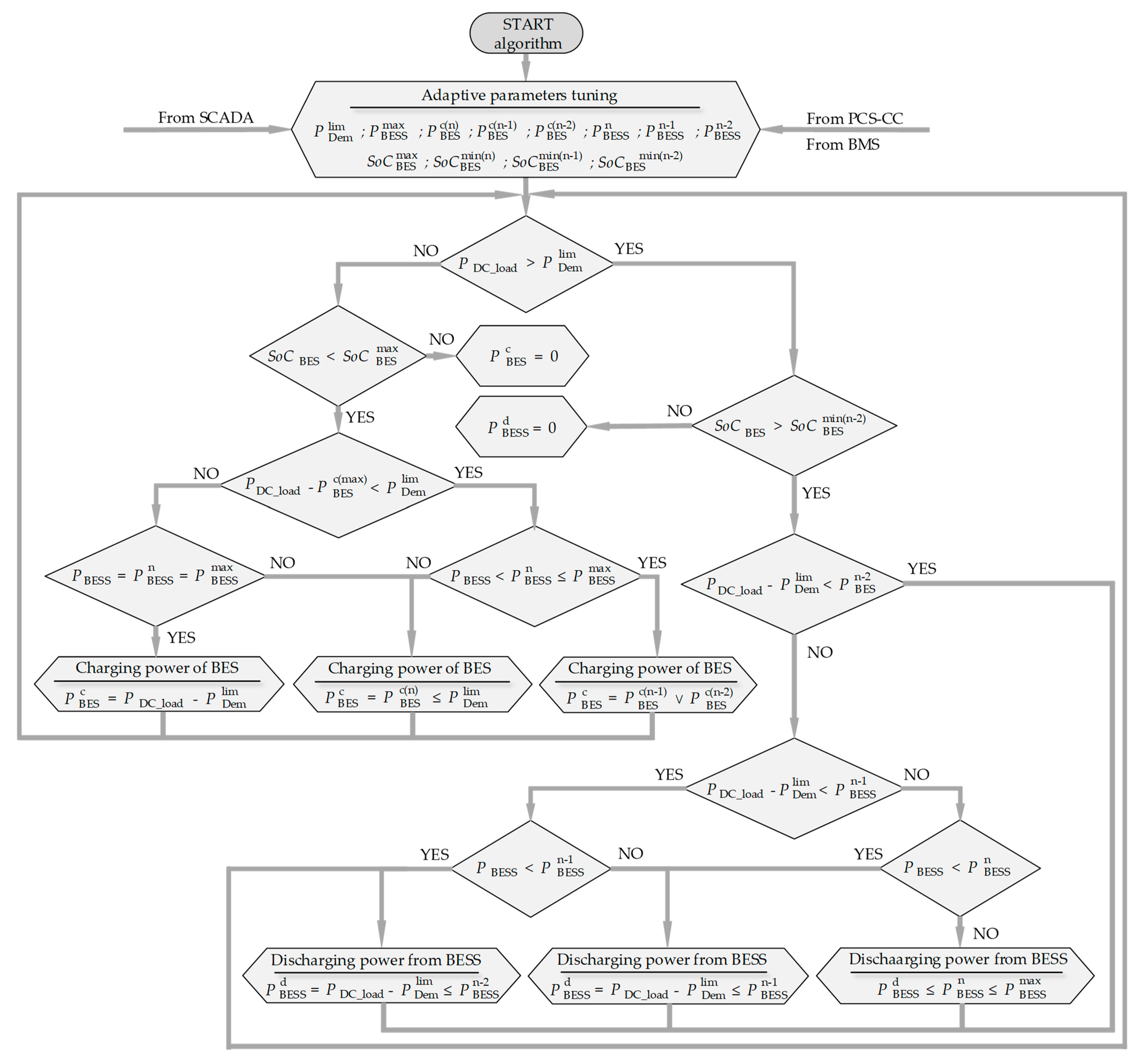
- —power limit of BESS in a one-threshold reduction strategy in the normal state of the BESS, when all of PCS and BES strings are available;
- —power limit of BESS in a two-threshold reduction strategy in a state of limited availability of the BESS, when at least one PCS or BES string is damaged or disconnected;
- —power limit of BESS in three-threshold reduction strategy in state of limited availability of the BESS, when at least two PCSs or BES strings are damaged or disconnected;
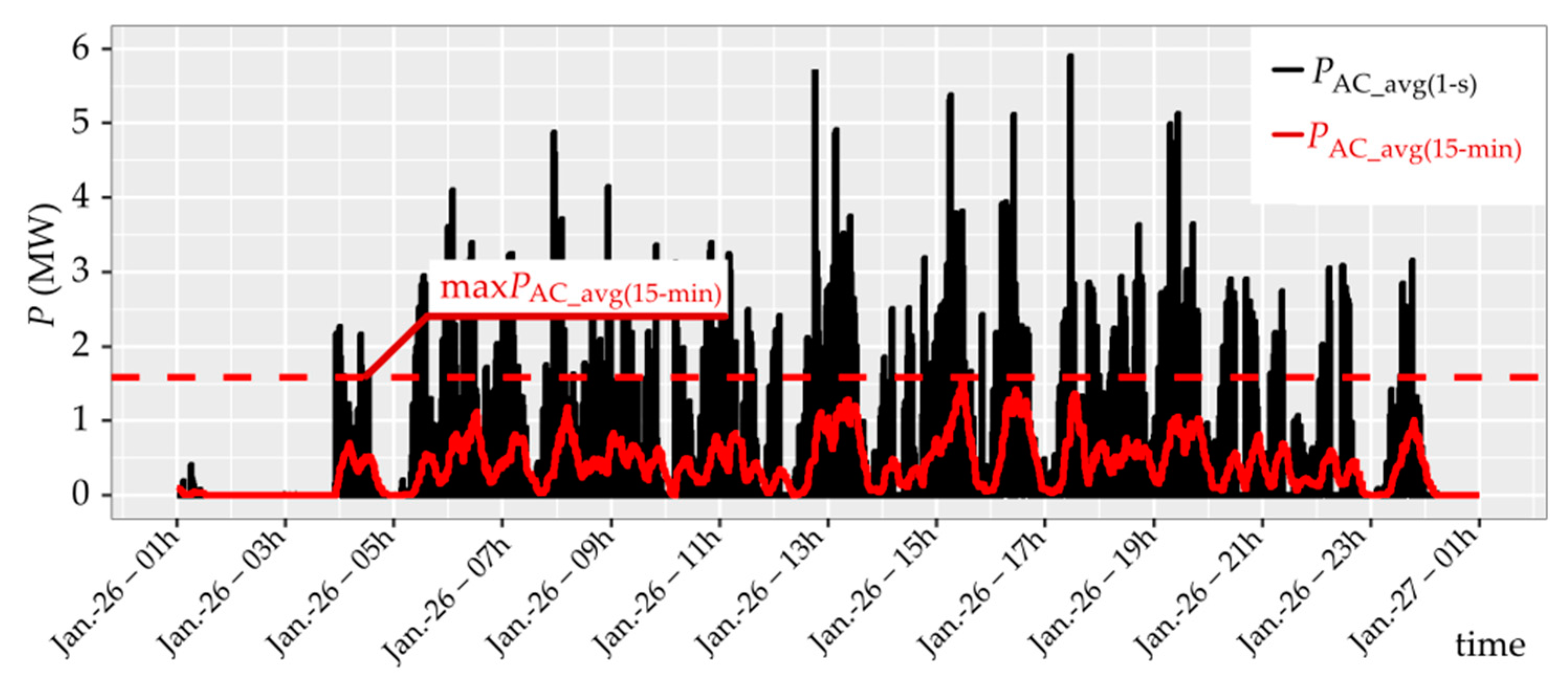
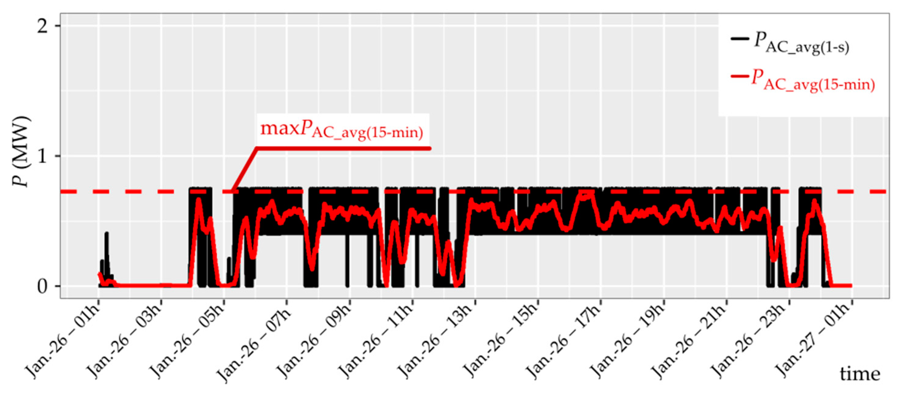
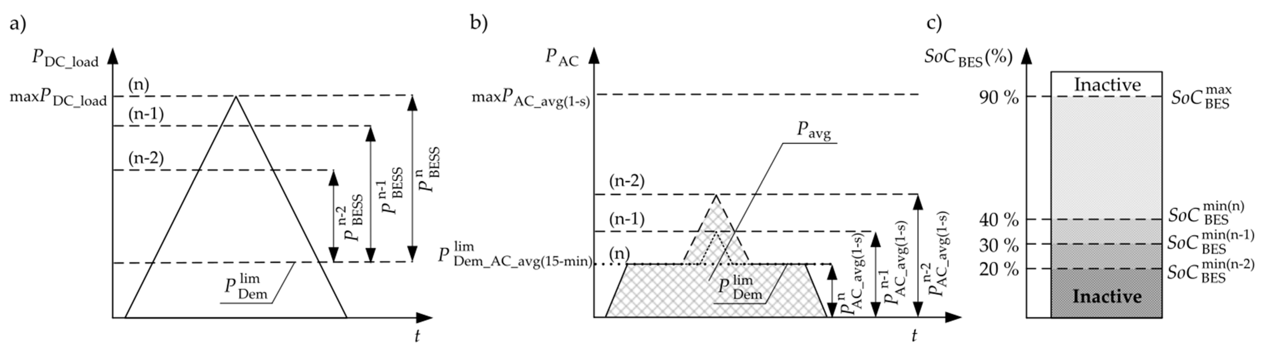
- —demanded power limit, parameter controlled by DROPT-FTC system, maximum value of 15 min averaged power ;
- ; ; —instantaneous powers on the AC side of traction substation: in normal state, n-1 state and n-2 state respectively.
- two-threshold reduction strategy, of so-called “top-down adaptation” [24] in which the maximum instantaneous power is reduced by balancing DC load power with the available power to be below the level: ;
- three-threshold reduction strategy, of so-called “top-down adaptation” in which the maximum instantaneous power is reduced by balancing DC load power with the available power to be below the level: .
- ➢
- the first-threshold is directly proportional to ;
- ➢
- the second-threshold depends on the available power of BESS when one PSC or BES fails;
- ➢
- the third-threshold is depends on the available power of BESS when two PCS or BES fails.
3.2. Control Algorithm of the DROPT-FTC
4. Case Study of the DROPT-FTC System
4.1. Available Power and Energy of Battery Energy Storage System
4.2. Multi-String Energy Storage System
5. Analysis of the DROPT-FTC with Proposed Fault-Tolerant Algorithm
5.1. Basic Parameters for Simulation Research
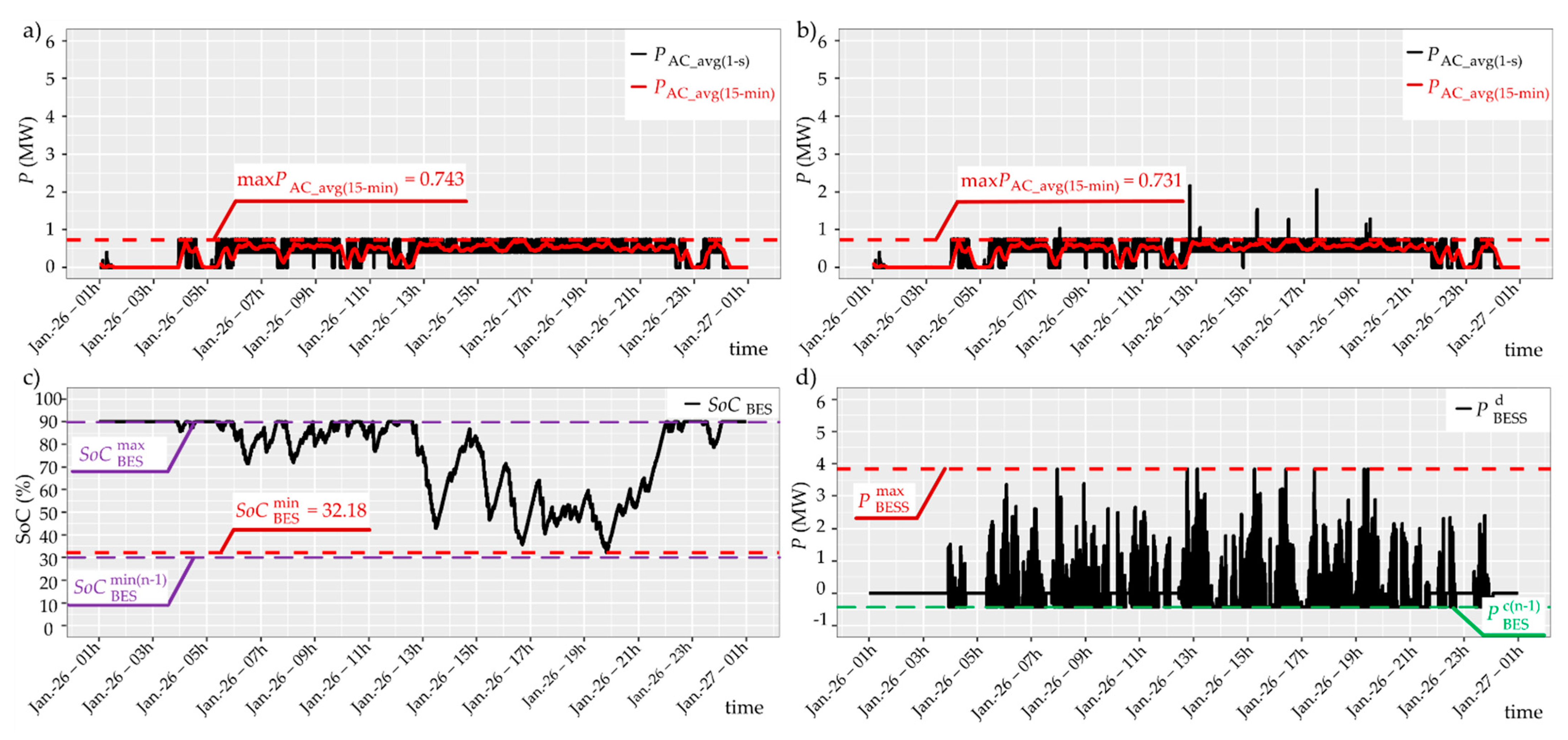
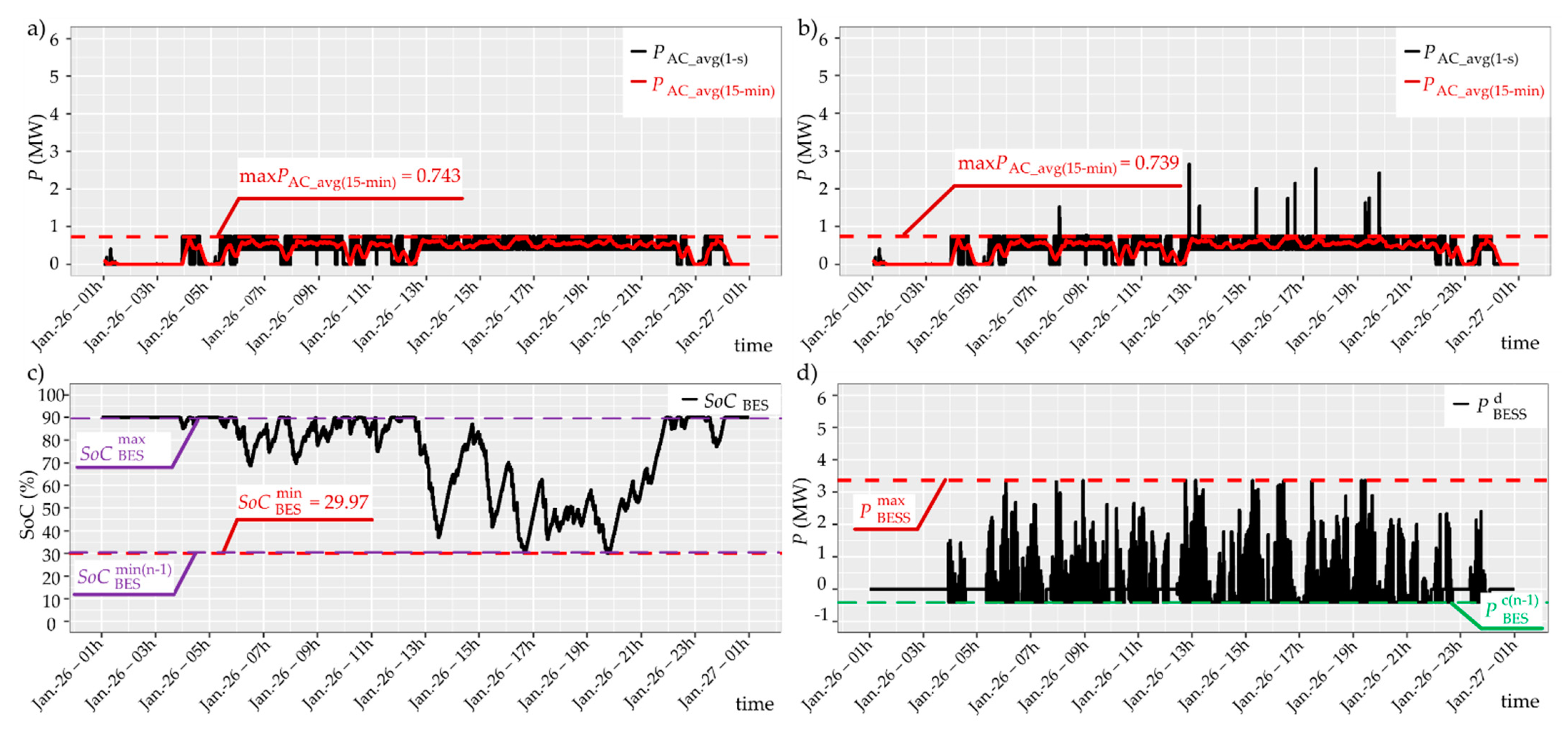
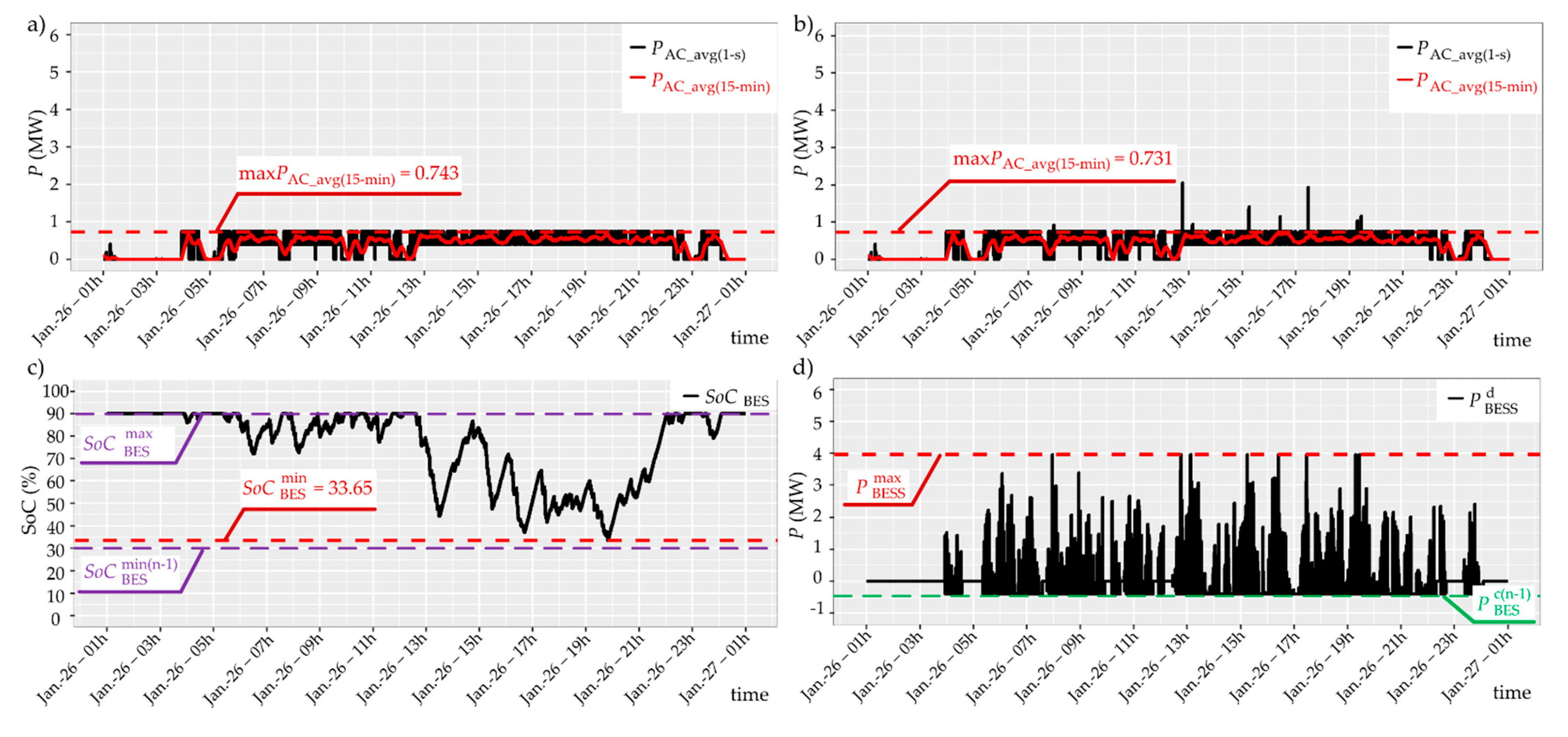
5.2. Result of Simulation Research
6. Discussion of the Simulation Results
Operational Expenditure
7. Conclusions
8. Future Work
Author Contributions
Funding
Institutional Review Board Statement
Informed Consent Statement
Data Availability Statement
Acknowledgments
Conflicts of Interest
Abbreviations and Nomenclature
| DROPT | Dynamic Reduction of Traction Substation Load |
| DROPT-FTC | Dynamic Reduction of Traction Substation Load with Fault-Tolerant Control |
| BESS | Battery Energy Storage System |
| BES | Battery Energy Storage |
| ES | Energy Storage |
| BMS | Battery Management System |
| PCS | Power Conversion System |
| PCS-CC | Power Conversion System—Converter Control |
| SCADA | Supervisory Control and Data Acquisition |
| CU | Control Unit |
| TS | Traction Substation |
| TR | Transformer |
| RC | Rectifier |
| L | Choke |
| PCC | Point of Common Coupling |
| AC | Alternating Current |
| DC | Direct Current |
| Rated power of traction substation | |
| Demanded, 15 min averaged power | |
| Reduced level of demanded, 15 min averaged power | |
| Demanded power limit—control parameter | |
| BESS power of DROPT-FTC system (summarised power of all PCS) | |
| Rated energy of DROPT-FTC system | |
| Maximum available energy of DROPT-FTC system in failure-free operation condition | |
| AC power flow—supply side of TS | |
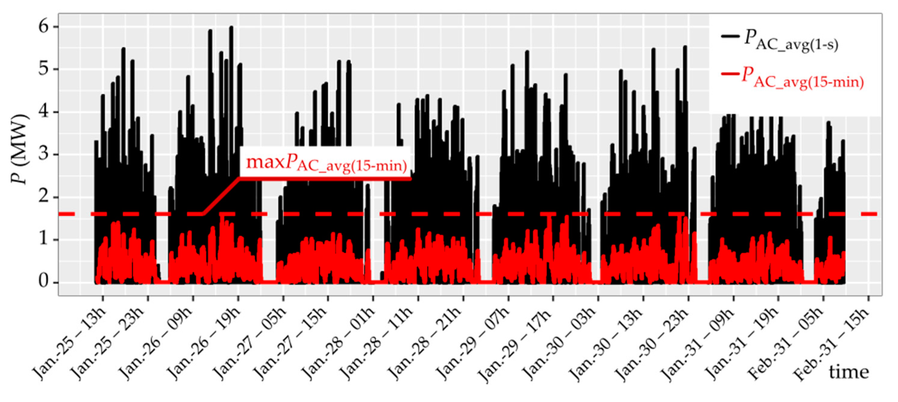
| Instantaneous AC power flow, averaged 1 s (1 s) | |
| Maximum value of AC power flow, averaged 1 s (1 s) | |
| AC power flow, averaged 15 min (15 min) | |
| DC power flow—output side of TS | |
| Maximum value of DC load power | |
| DC load power of TS with DROPT-FTC | |
| n | Normal state of the BESS |
| n-1 | Reduction of available power or energy, and charging power by one-level |
| n-2 | Reduction of available power or energy, and charging power by two-level |
| Current BESS power | |
| Maximum available power of BESS in case of n; n-1; n-2 status | |
| Maximum available power of BESS in case of n status | |
| Maximum available power of BESS in case of n-1 status | |
| Maximum available power of BESS in case of n-2 status | |
| Current BESS power level, according to n; n-1; n-2 status | |
| Current BES power level, according to n; n-1; n-2 status | |
| Total power of available PCS systems, according to n; n-1; n-2 status | |
| Power taken from BESS | |
| Charging power of BES, according to n; n-1; n-2 status | |
| Maximum charging power of BES in case of n status | |
| Maximum charging power of BES in case of n-1 status | |
| Maximum charging power of BES in case of n-2 status | |
| Current BES energy level, according to n; n-1; n-2 status | |
| Maximum available energy of BES in case of n; n-1; n-2 status | |
| Maximum available energy of BES in case of n status | |
| Maximum available energy of BES in case of n-1 status | |
| Maximum available energy of BES in case of n-2 status | |
| Current State of Charge of BES | |
| Maximum level of state of charge (100%) | |
| Maximum level of state of charge (it should not exceed 90% for Li-Ion technology) | |
| Minimum level of state of charge, according to n; n-1; n-2 status | |
| Minimum level of state of charge in case of n status | |
| Minimum level of state of charge in case of n-1 status | |
| Minimum level of state of charge in case of n-2 status | |
| State of Charge of BES, according to n; n-1; n-2 state | |
| Depth of Discharge of BES | |
| C-rate | A measure of the rate at which a battery is being charge or discharge |
| Operational expenditure of Traction Substation | |
| SPBT | Simple Payback Time |
| TOU | Time-of-use |
| OBESS | On-Board Energy Storage System |
| WESS | Wayside Energy Storage System |
| TESS | Trackside Energy Storage System |
| HESS | Hybrid Energy Storage System |
| HSRS | High-Speed Railway Substation |
| SHB | Service Headway Breaking |
| ESDI | Extending Stopping Distance Interval |
| NiMH | Nickel Metal Hydride |
| LFP (LiFePO4) | Lithium Iron Phosphate |
| NMC | Nickle Manganese Cobalt |
References
- Barrero, R.; Tackoen, X.; Van Mierlo, J. Improving energy efficiency in public transport: Stationary supercapacitor based Energy Storage System for a metro network. In Proceedings of the 2008 IEEE Vehicle Power and Propulsion Conference, Harbin, China, 3–5 September 2008. [Google Scholar] [CrossRef]
- Jefimowski, W. Stationary energy storage system in a 3 kV DC—The conception comparison. MATEC Web Conf. 2018, 180, 02013. [Google Scholar] [CrossRef] [Green Version]
- Soler-Nicolau, M.; Mera, J.M.; López, J.; Cano-Moreno, J.D. Improving power supply design for high speed lines and 2 × 25 systems using a genetic algorithm. Electr. Power Energy Syst. 2018, 99, 309–322. [Google Scholar] [CrossRef]
- Kim, H.; Heo, J.-H.; Park, J.-Y.; Yoon, Y.T. Impact of Battery Energy Storage System Operation Strategy on Power System: An Urban Railway Load Case under a Time-of-Use Tariff. Energies 2017, 10, 68. [Google Scholar] [CrossRef] [Green Version]
- Sumpavakup, C.; Ratniyomchai, T.; Kulworawanichpong, T. Optimal energy saving in DC railway system with on-board energy storage by using peak demand cutting strategy. J. Mod. Transp. 2017, 25, 223–235. [Google Scholar] [CrossRef] [Green Version]
- Kulworawanichpong, T. Multi-train modelling and simulation integrated with traction power supply solver using simplified Newton-Raphson method. J. Mod. Transp. 2015, 23, 241–251. [Google Scholar] [CrossRef] [Green Version]
- Gu, Q.; Tang, T.; Cao, F.; Karimi, G.-R.; Song, Y. Peak Power Demand and Energy Consumption Reduction Strategies for Trains under Moving Block Signalling System. Hindawi Publ. Corp. Math. Probl. Eng. 2013, 2013, 940936. [Google Scholar] [CrossRef]
- Su, S.; Tang, T.; Wang, Y. Evaluation of Strategies to Reducing Traction Energy Consumption of Metro Systems Using an Optimal Train Control Simulation Model. Energies 2016, 9, 105. [Google Scholar] [CrossRef]
- Lin, F.; Liu, S.; Yang, Z.; Zhao, Y.; Yang, Z.; Sun, H. Multi-Train Energy Saving for Maximum Usage of Regenerative Energy by Dwell Time Optimization in Urban Rail Transit Using Genetic Algorithm. Energies 2016, 9, 208. [Google Scholar] [CrossRef] [Green Version]
- Radu, P.-V.; Lewandowski, M.; Szelag, A. On-Board and Wayside Energy Storage Devices Applications in Urban Transport Systems-Case Study Analysis for Power Applications. Energies 2020, 13, 2013. [Google Scholar] [CrossRef] [Green Version]
- Sumpavakup, C.; Suwannakijborihan, S.; Ratniyomchai, T.; Kulworawanichpong, T. Peak Demand Cutting Strategy with an On-Board Energy Storage System in Mass Rapid Transit. Iran. J. Sci. Technol. Trans. Electr. Eng. 2018, 42, 49–62. [Google Scholar] [CrossRef]
- Hedlund, M.; Lundin, J.; de Santiego, J.; Abrahmsson, J.; Bernholff, H. Flywheel Energy Storage for Automotive Applications. Energies 2015, 8, 10636–10663. [Google Scholar] [CrossRef] [Green Version]
- Lin, F.; Xuyang, L.; Zhao, Y.; Yang, Z. Control Strategies with Dynamic Threshold Adjustment for Supercapacitor Energy Storage System Considering the Train and Substation Characteristics in Urban Rail Transit. Energies 2016, 9, 257. [Google Scholar] [CrossRef]
- Khodeparastan, M.; Dutta, O.; Mohamed, A. Wayside Energy Storage System for Peak Demand Reduction in Electric Rail Systems. In Proceedings of the 2018 IEEE Industry Applications Society Annual Meeting (IAS), Portland, OR, USA, 23–27 September 2018. [Google Scholar] [CrossRef]
- Lamedica, R.; Ruvio, A.; Palagi, L.; Mortelliti, N. Optimal Siting and Sizing of Wayside Energy Storage Systems in a D.C. Railway line. Energies 2020, 13, 6271. [Google Scholar] [CrossRef]
- Roch-Dupré, D.; López- López, Á.-J.; Pecharromán, R.-R.; Cucala, A.-P.; Fernández-Cardador, A. Analysis of the demand charge in DC railway systems and reduction of its economic impact with Energy Storage System. Elsevier Electr. Power Energy Syst. 2017, 93, 459–467. [Google Scholar] [CrossRef]
- Jarnut, M.; Kaniewski, J.; Protsiuk, V. Energy storage system for peak-power reduction of traction substation. In Proceedings of the 2018 Innovative Materials and Technologies in Electrical Engineering (i-MITEL), Sulecin, Poland, 18–20 April 2018. [Google Scholar] [CrossRef]
- Calderaro, V.; Galdi, V.; Graber, G.; Picollo, A.; Capasso, A.; Lamedica, R.; Ruvio, A. Energy Management of Auxliary Battery Substation Supporting High-Speed Train on 3 kV DC Systems. In Proceedings of the 2015 International Conference on Renewable Energy Research and Applications (ICRERA), Palermo, Italy, 22–25 November 2015. [Google Scholar] [CrossRef]
- Kwon, K.; Choi, J. Single-Phase 13-Level Power Conditioning System for Peak Power Reduction of a High-Speed Railway Substation. Energies 2019, 12, 4405. [Google Scholar] [CrossRef] [Green Version]
- Jefimowski, W.; Nikitenko, A. Case study of stationary energy storage device in a 3 kV DC traction system. MATEC Web Conf. 2018, 180, 02005. [Google Scholar] [CrossRef] [Green Version]
- Qin, Q.; Guo, T.; Lin, F.; Yang, Z. Energy Transfer Strategy for Urban Rail Transit Battery Energy Storage System to reduce Peak Power of Traction Substation. IEEE Trans. Veh. Technol. 2019, 68, 11714–11724. [Google Scholar] [CrossRef]
- Guo, T.; Yang, Z.; Lin, F.; Xiong, S. Optimization of peak load shifting control strategy for battery energy storage system used in urban rail transit. In Proceedings of the IECON 2017—43rd Annual Conference of the IEEE Industrial Electronics, Beijing, China, 29 October–1 November 2017. [Google Scholar] [CrossRef]
- Xia, H.; Chen, H.; Yang, Z.; Lin, F.; Wang, B. Optimal Energy Management, Location and Size for Stationary Energy Storage System in a Metro Line Based on Genetic Algorithm. Energies 2015, 8, 11618–11640. [Google Scholar] [CrossRef]
- Szott, M.; Wermiński, S.; Jarnut, M.; Kaniewski, J. Battery peak-power reduction system of traction substation with two-threshold limitation. Przegląd Elektrotechniczny 2020. [Google Scholar] [CrossRef]
- Szott, M.; Wermiński, S.; Jarnut, M.; Kaniewski, J.; Benysek, G. Battery Energy Storage System for Emergency Supply and Improved Reliability of Power Networks. Energies 2021, 14, 720. [Google Scholar] [CrossRef]
- Miao, Y.; Hynan, P.; von Jouanne, A.; Yokochi, A. Current Li-Ion Battery Technologies in Electric Vehicles and Opportunities for Advancement. Energies 2019, 12, 1074. [Google Scholar] [CrossRef] [Green Version]
- Koniak, M.; Czerepicki, A. Selection of battery pack parameters for an electric vehicle based on performance requirements. In Proceedings of the IOP Conference Series: Material Science and Engineering, Bangkok, Thailand, 21–23 April 2017. [Google Scholar] [CrossRef] [Green Version]
- EN 50470-3: 2009. Electricity Metering Equipment (a.c.) Part 3: Particular Requirements—Static Meters for Active Energy (Class Index A, B and C); ISS: Beograd, Serbia, 2009. [Google Scholar]
- EN 62055-31. Electricity Metering—Payment Systems—Part 31: Particular Requirements—Static Payment Meters for Active Energy (Classes 1 and 2); IEC: Geneva, Switzerland, 2005. [Google Scholar]
- Wei, Z.; Zhao, J.; Ji, D.; Tseng, K.J. A multi-timescale estimator for battery state of charge and capacity dual estimation based on an online identified model. Appl. Energy 2017, 204, 1264–1274. [Google Scholar] [CrossRef]
- Chen, L.; Tong, Y.; Dong, Z. Li-Ion Battery Performance Degradation Modelling for the Optimal Design and Energy Management of Electrified Propulsion Systems. Energies 2020, 13, 1629. [Google Scholar] [CrossRef] [Green Version]
- Wikner, E.; Thiringer, T. Extending Battery Lifetime by Avoiding High SOC. Appl. Sci. 2018, 8, 1825. [Google Scholar] [CrossRef] [Green Version]
- Cheng, Y.-I.; Liu, Y.-H.; Hesse, H.C.; Naumann, M.; Trung, C.N.; Josson, A. A PSO-Optimized Fuzzy Logic Control-Based Charging Method for Individual Household Battery Storage System within a Community. Energies 2018, 11, 469. [Google Scholar] [CrossRef] [Green Version]
- Huang, M.-C.; Yang, C.-H.; Chiang, C.-C.; Chiu, S.-C.; Chen, Y.-F.; Lin, C.-Y.; Wang, L.-Y.; Li, Y.-L.; Yang, C.-C.; Chang, W.-S. Influence of High Loading on the Performance of Natural graphite-Based Al Secondary Batteries. Energies 2018, 11, 2760. [Google Scholar] [CrossRef] [Green Version]
- Haidl, P.; Buchroithner, A.; Schweighofer, B.; Bader, M.; Wegleiter, H. Lifetime Analysis of Energy Storage Systems Sustainable Transportation. Sustainability 2019, 11, 6731. [Google Scholar] [CrossRef] [Green Version]
- Kurzweil, P.; Shamonin, M. State-of-Charge Monitoring by Impedance Spectroscopy during Long-Term self-Discharge of Supercapacitors and Lithium-Ion Batteries. Batteries 2018, 4, 35. [Google Scholar] [CrossRef] [Green Version]
- EN 50160. Voltage Characteristics of Electricity Supplied by Public Electricity Networks; German Institute for Standardisation: Berlin, Germany, 2010. [Google Scholar]


| TS | DROPT-FTC | ||||||
|---|---|---|---|---|---|---|---|
| (MW) | (MW) | (MW) | (MW) | (MWh) | (MWh) | (%) | (%) |
| 6.30 | 3.10 | 0.75 | 5.50 | 1.80 | 0.90 | 90 | 40 |
| Parameters | ∑PCS | PCS (1) | PCS (2) | PCS (3) | ∑BES | BES (1) | BES (2) | BES (3) |
|---|---|---|---|---|---|---|---|---|
| (MW) | 5.500 | 2.000 | 2.000 | 1.500 | - | - | - | - |
| (MWh) | - | - | - | - | 1.800 | 0.655 | 0.655 | 0.490 |
| Parameters | ∑PCS | PCS (1) | PCS (2) | PCS (3) | PCS (4) | ∑BES | BES (1) | BES (2) | BES (3) | BES (4) |
|---|---|---|---|---|---|---|---|---|---|---|
| (MW) | 5.500 | 1.375 | 1.375 | 1.375 | 1.375 | - | - | - | - | - |
| (MWh) | - | - | - | - | - | 1.800 | 0.450 | 0.450 | 0.450 | 0.450 |
| Parameters | Base | Three-String BESS | Four-String BESS | |||||||
|---|---|---|---|---|---|---|---|---|---|---|
| Rated | Normal (n) | CASE IA (n-1) | CASE IB (n-1) | CASE IC (n-2) | CASE IIA (n-1) | CASE IIB (n-1) | CASE IIIA (n-1) | CASE IIIB (n-1) | CASE IIIC (n-2) | |
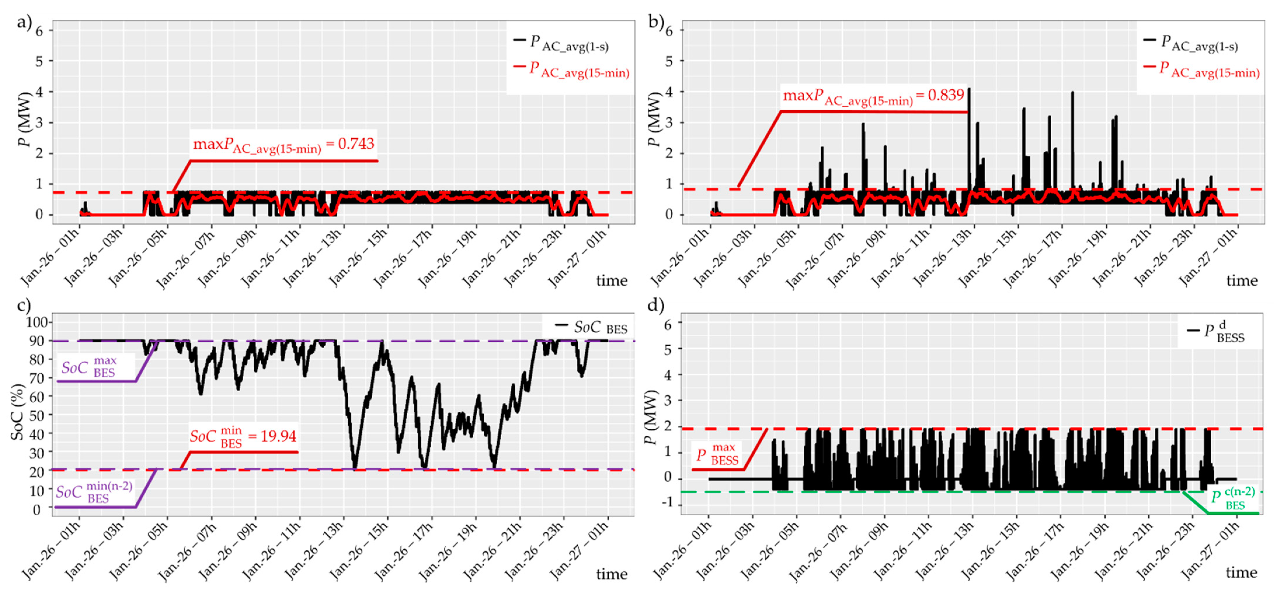
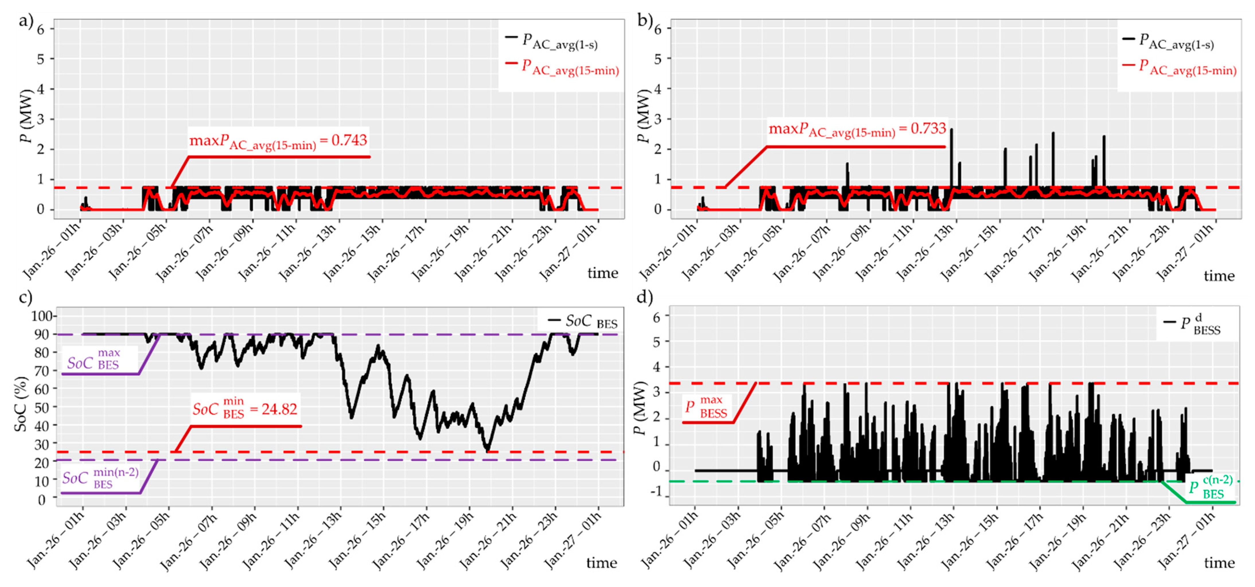
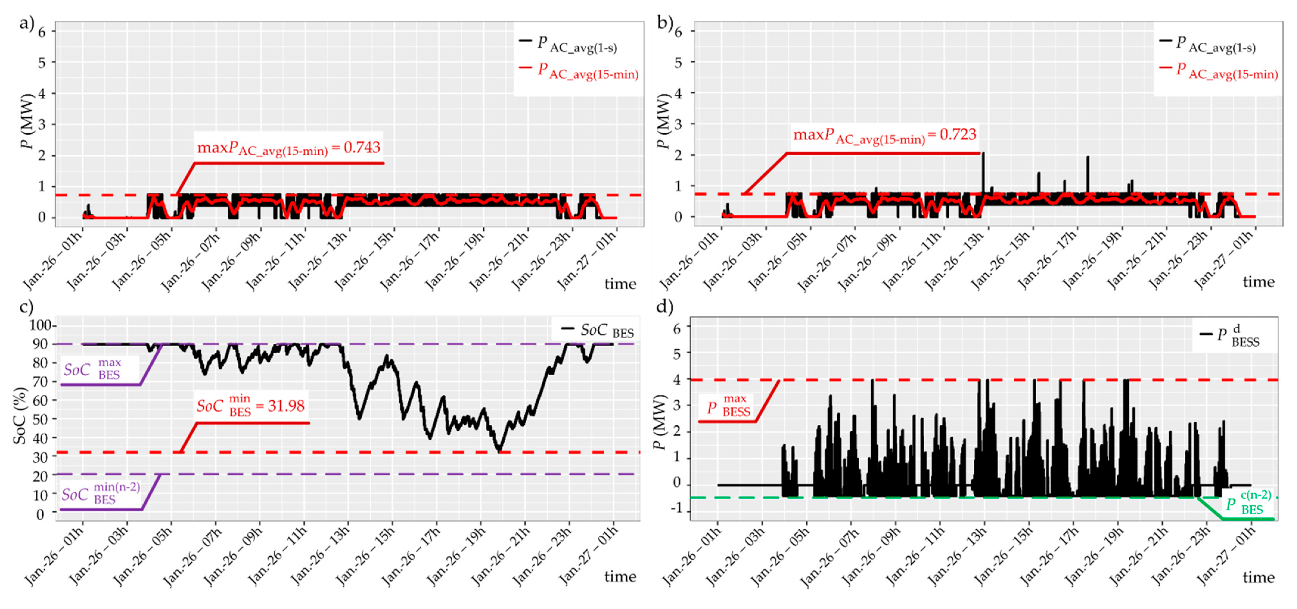
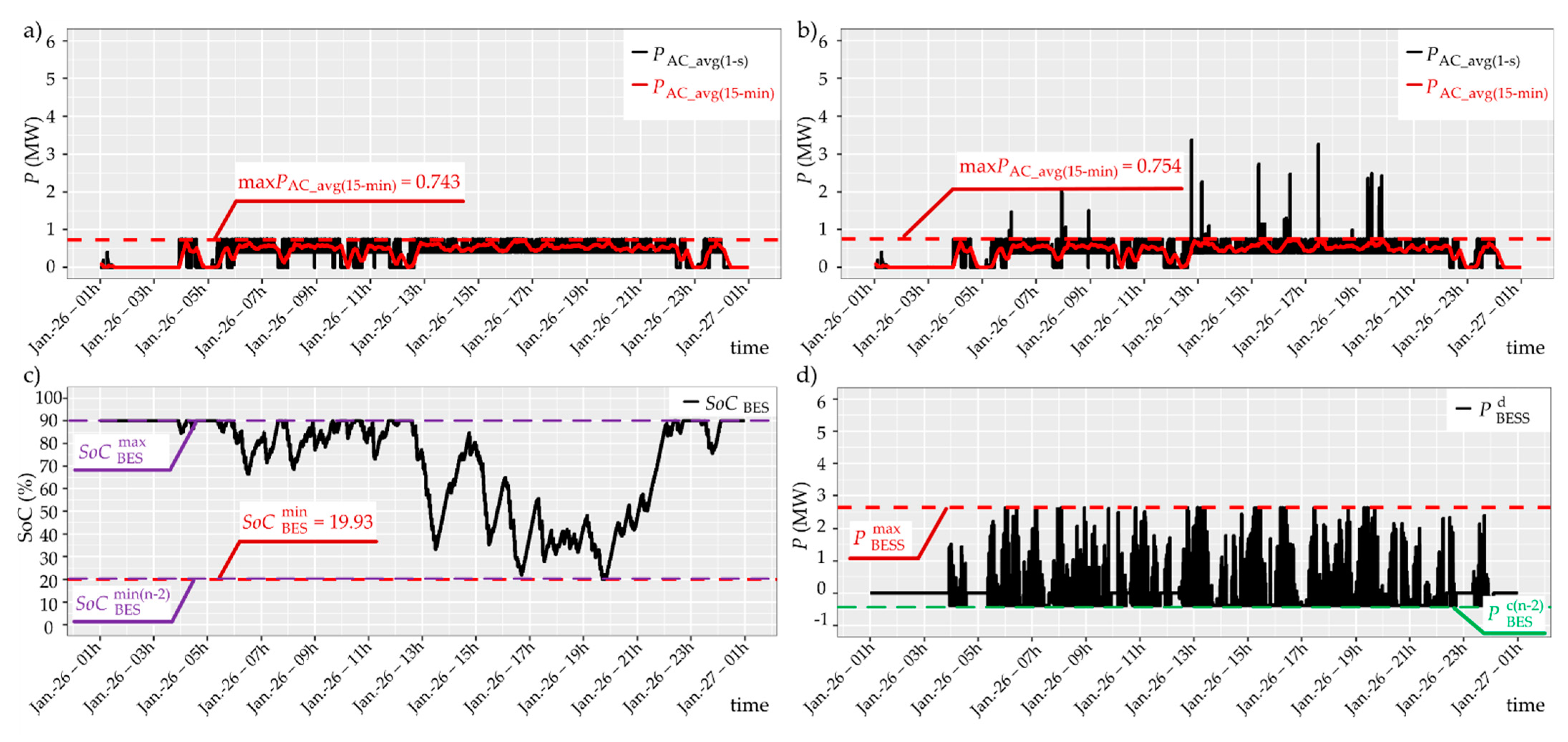
| (MW) | 5.500 | 5.260 | 3.840 | 3.840 | 1.920 | 3.360 | 3.360 | 3.960 | 3.960 | 2.630 |
| (MWh) | 1.800 | 0.900 | 0.786 | 0.916 | 0.458 | 0.687 | 0.802 | 0.810 | 0.945 | 0.630 |
| (%) | 100 | 90 | 90 | 90 | 90 | 90 | 90 | 90 | 90 | 90 |
| (%) | 0 | 40 | - | - | - | - | - | - | - | - |
| (%) | - | - | 30 | - | - | 30 | - | 30 | - | - |
| (%) | - | - | - | 20 | 20 | - | 20 | - | 20 | 20 |
| (MW) | - | 0.420 | 0.400 | 0.380 | 0.380 | 0.400 | 0.380 | 0.400 | 0.380 | 0.380 |
| Parameters | Base | Three-String BESS | Four-String BESS | ||||||
|---|---|---|---|---|---|---|---|---|---|
| Normal (n) | CASE IA (n-1) | CASE IB (n-1) | CASE IC (n-2) | CASE IIA (n-1) | CASE IIB (n-1) | CASE IIIA (n-1) | CASE IIIB (n-1) | CASE IIIC (n-2) | |
| (MW) | 5.260 | 3.840 | 3.840 | 1.920 | 3.360 | 3.360 | 3.960 | 3.960 | 2.630 |
| (MWh) | 0.900 | 0.786 | 0.916 | 0.458 | 0.687 | 0.802 | 0.810 | 0.945 | 0.630 |
| (%) | 90 | 90 | 90 | 90 | 90 | 90 | 90 | 90 | 90 |
| (%) | 40 | 30 | 20 | 20 | 30 | 20 | 30 | 20 | 20 |
| (MW) | 0.420 | 0.400 | 0.380 | 0.380 | 0.400 | 0.380 | 0.400 | 0.380 | 0.380 |
| (MW) | 0.750 | 0.750 | 0.750 | 0.750 | 0.750 | 0.750 | 0.750 | 0.750 | 0.750 |
| (MW) | 0.743 | 0.731 | 0.728 | 0.839 | 0.739 | 0.732 | 0.731 | 0.723 | 0.754 |
Publisher’s Note: MDPI stays neutral with regard to jurisdictional claims in published maps and institutional affiliations. |
© 2021 by the authors. Licensee MDPI, Basel, Switzerland. This article is an open access article distributed under the terms and conditions of the Creative Commons Attribution (CC BY) license (https://creativecommons.org/licenses/by/4.0/).
Share and Cite
Szott, M.; Jarnut, M.; Kaniewski, J.; Pilimon, Ł.; Wermiński, S. Fault-Tolerant Control in a Peak-Power Reduction System of a Traction Substation with Multi-String Battery Energy Storage System. Energies 2021, 14, 4565. https://doi.org/10.3390/en14154565
Szott M, Jarnut M, Kaniewski J, Pilimon Ł, Wermiński S. Fault-Tolerant Control in a Peak-Power Reduction System of a Traction Substation with Multi-String Battery Energy Storage System. Energies. 2021; 14(15):4565. https://doi.org/10.3390/en14154565
Chicago/Turabian StyleSzott, Marcin, Marcin Jarnut, Jacek Kaniewski, Łukasz Pilimon, and Szymon Wermiński. 2021. "Fault-Tolerant Control in a Peak-Power Reduction System of a Traction Substation with Multi-String Battery Energy Storage System" Energies 14, no. 15: 4565. https://doi.org/10.3390/en14154565
APA StyleSzott, M., Jarnut, M., Kaniewski, J., Pilimon, Ł., & Wermiński, S. (2021). Fault-Tolerant Control in a Peak-Power Reduction System of a Traction Substation with Multi-String Battery Energy Storage System. Energies, 14(15), 4565. https://doi.org/10.3390/en14154565