Article

Experimental Studies of the Effect of Design and Technological Solutions on the Intensification of an Underground Coal Gasification Process

1
Belt and Road Initiative Institute for Chinese-European Studies (BRIICES), Guangdong University of Petrochemical Technology, Maoming 525000, China
2
Department of Mining Engineering and Education, Dnipro University of Technology, 49005 Dnipro, Ukraine
3
Institute of the Center of Renewable Energy and Energy Efficiency, Universidad Nacional de San Agustin de Arequipa, Arequipa 04000, Peru
*
Author to whom correspondence should be addressed.
Energies 2021, 14(14), 4369; https://doi.org/10.3390/en14144369
Submission received: 21 June 2021 / Revised: 12 July 2021 / Accepted: 15 July 2021 / Published: 20 July 2021

Abstract

:
This paper represents the results of experimental studies of physical modeling of the underground coal gasification process in terms of implementation of design and technological solutions aimed at intensification of a gasification process of thin coal seams. A series of experimental studies were performed in terms of a stand unit with the provided criteria of similarity to field conditions as well as kinetics of thermochemical processes occurring within a gas generator. Hard coal (high volatile bituminous coal) was selected as the raw material to be gasified, as that coal grade prevails in Ukrainian energy balance since it is represented by rather great reserves. Five blow types were tested during the research (air, air–steam, oxygen–steam, oxygen–enriched, and carbon dioxide and oxygen). As a result, the effect of tightness of a gas generator on the quantitative and qualitative parameters of coal gasification while varying the blow by reagents and changing the pressure in a reaction channel has been identified. Special attention was paid to the design solutions involving blow supply immediately into the combustion face of a gas generator. The experimental results demonstrate maximum efficiency of the applied gas generator design involving flexible pipelines and activator in the reaction channel and a blow direction onto the reaction channel face combined with blow stream reversing which will make it possible to improve caloricity of the generator gas up to 18% (i.e., from 8.4 to 12.8 MJ/m3 depending upon a blow type). Consideration of the obtained results of physical modelling can be used with sufficient accuracy to establish modern enterprises based on the underground coal seam gasification; this will help develop more efficiently the substandard coal reserves to generate heat energy as well as power-producing and chemical raw material. The research conclusions can provide technical reference for developing a new generation of underground coal gasification technology.

1. Introduction

Currently, different studies are being carried out analyzing deep coal processing aimed both at manufacturing of energy products for electric energy generation and obtaining valuable chemical products [1,2,3]. Use of coal to generate syngas, methanol, liquid fuel, and other deficit products is the tendency of special topicality [4,5,6]. That makes it possible to consider coal as a reliable alternative source of obtaining carbohydrate raw material, especially in terms of exhaustion of oil and gas reserves due to growing volumes of their consumption and low rates of additional exploration of oil-and-gas fields [7,8,9,10,11].
Currently, production of energetically valuable liquid fuel from coal is the industrially developed process; in this context, reactions of incomplete coal oxidation are quite often to have in surface gas generators [12,13]. A main disadvantage of surface gas generators is their high cost and considerable expenditures for coal extraction and transportation to the place of processing [14]. Underground coal gasification (UCG) is a prospective tendency of deep coal processing; that provides the reactions of incomplete coal oxidation in terms of underground conditions immediately within the place of coal seam occurrence—in an underground gas generator—with production of gas (after its corresponding surface-based processing), which is close to natural gas in its consumer properties [15,16]. Moreover, the gas of underground coal gasification may be the raw material for getting syngas, methanol, ammonia, carbamide, and other valuable chemical products [17,18,19,20,21,22]. At the same time, it is critically important to provide environmental safety during mining [23,24,25,26,27].
Underground gasification of solid fuel is an important tendency in the development of natural fuel deposits; it means underground fuel transformation into a combustible gas for its further energetic and technological use after its outlet to the earth’s surface [28]. Main feature of underground coal gasification is that such mining method helps develop both off-balance and non-commercial coal reserves [29,30,31,32]. The non-traditional mining method of coal deposits opens new prospects in the development of coal seams with complicated mining and geological modes of occurrence. It combines extraction, dressing, and complex processing [33,34,35] with detailed study of rock mass behavior [36,37,38,39,40,41].
The essence of the technology of underground coal gasification is in drilling of wells from the earth’s surface towards a coal seam by means of directed drilling, their linkage within a seam by one of the known techniques with further coal seam ignition, creation of the conditions for coal transformation right underground into a combustion gas, and removal of the produced gas through the wells onto the earth’s surface [42,43,44].
Advantages of the mentioned technology are as follows: coal is not hoisted to the surface, there are no large rock volumes to be placed somewhere, the terrain integrity is not disturbed, there is no subsidence due to formation of underground voids, and there is no need in using additional chemical reagents that have negative impact on the environment [45,46,47]. Thus, all the technological operations of underground coal gasification are performed from the earth’s surface without miners’ underground operations. The technology belongs to so-called clean coal technologies, it is environmentally safe, and it can become a great alternative to extraction [48,49,50,51,52].
A process of underground coal gasification (UCG) consists of the primary chemical reactions within an oxidizing zone, a reaction channel of a gas generator [53]. A combustion (oxidizing) process in that zone is accompanied by the formation of carbon monoxides and dioxides. A reducing zone of a gas generator shows the processes accompanied by the secondary reducing reactions with the formation of gasification products [54,55]. A degree of coal transformation into gasification products depends on certain key conditions and parameters: ultimate composition, texture and structure of a coal seam and roof and floor rocks, hydrogeological conditions, pressure, temperature, composition of a blow mixture, directionality and duration of blow contact in space and time with a combustion face of an underground gas generator [56,57].
Currently, there is sufficient number of studies analyzing the features of design and technological solutions in terms of expediency of underground gas generator tightness [58,59,60,61], methods of supply and directionality of blow flows with the provided adaptivity and intensification of the processes of coal seam gasification [62,63,64,65] including controlled retracting injection point (CRIP) system [66,67], influence of mining and geological conditions of coal seam occurrence on the underground gasification process [68,69,70,71,72], and influences of underground coal gasification on the environment [46,58,73,74,75,76].
Application of different technical means, methods, and techniques as well as physical fields makes it possible to intensify the UCG process by effecting two objects: immediate coal mass and blow flows injected into the combustion face of an underground gas generator [77,78,79,80,81,82].
Tightness of the gas generator design is provided by injection-stowing operations within the deformed layers of the rocks enclosing the seam [83]. Stowing operations are performed with the consideration of changes in geomechanical parameters, parameters of a temperature field of the “rock mass—gas generator” system, changes in the advance rate of a combustion face of a gas generator, and increase in the gasified area in time and space [84,85,86]. While using injection stowing in terms of gasification of thin coal seams, ground subsidence is not more than 11–18% of the coal seam thickness [87].
Introduction of injection stowing of the deformed natural roof rock and the gasified space within the UCG stations in the underground gas generator design will ensure the mobility of a coal seam gasification process owing to the expansion of the area for the technology implementation. Artificial leak-tightening of a gas generator helps increase the criteria of controllability, compactness, environmental credentials, and safety of the process, which will allow performing the underground coal gasification process in the adapted modes of pressure and temperatures. That stipulates the growth of quantitative and qualitative indices of the UCG process since a set of factors, among which increased pressure in a reaction channel and features of the underground gas generator design are the key ones, results in the considerable losses of blow and generator gas during the coal seam gasification [88,89].
The research objective is to carry out the experimental modeling and study the effect of design and technological solutions, which influence immediately the degree of efficiency of the underground coal gasification process.
To reach the objective the authors, based on the experimental studies, strive to identify the effect of gas generator tightness on the quantitative and qualitative parameters of coal gasification (loss of blow and gas; changes in heat conductivity, temperature, and combustion heat as well as in the output of combustible generator gases and chemical products) in terms of blow variation by reagents and changing pressure in a reaction channel as well as to determine the effect of design and technical solutions for blow supply immediately onto the combustion face of a gas generator (loss of blow and gas, pressure, coal, advance rate and time that the main processes are achieving) depending on the type of gas generator design.

2. Materials and Methods

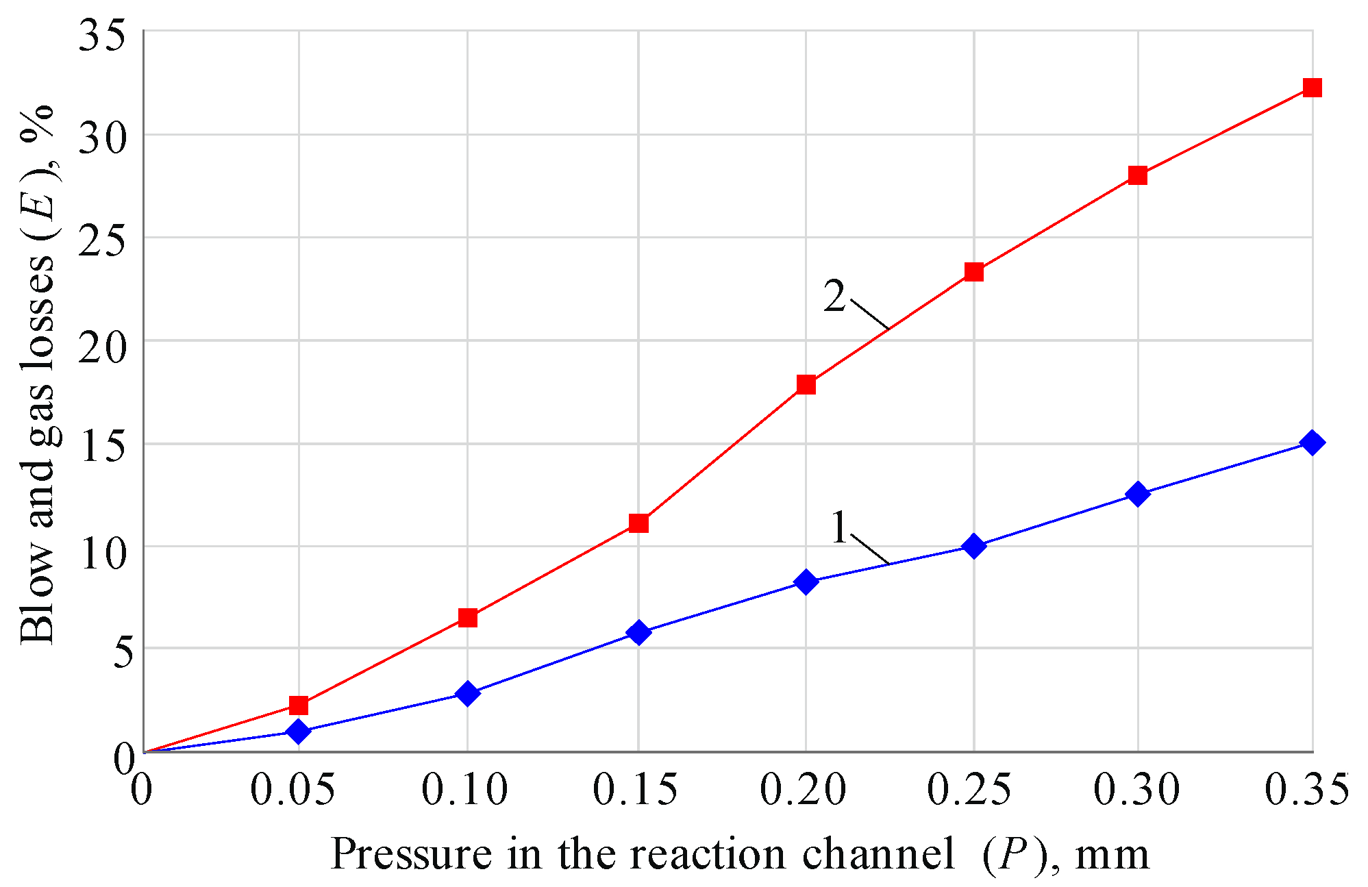
2.1. Determining the Sufficient Tightness of a Gas Generator

While substantiating the sufficient tightness of an underground gas generator, the following was considered:
(1)
Permeability of the coal-overlaying thickness taking into account natural and artificial fractures of the coal-overlaying thickness without injection stowing of the deformed rocks is determined according to the formula (1):
K c . o . t = i = 1 n k p i h r . l i P r . r h r . c P r . c ,
where K c . o . t is coefficient of permeability taking into account natural and artificial fractures, of the coal-overlaying thickness before stowing operations:
k p i is coefficient of permeability taking into account natural and artificial fractures of the rock layers of the roof before stowing operations; h r . l i is thickness of rock layers of the roof, m; P r . r is pressure within the roof rocks, MPa; h r . c is thickness of reaction channel, m; and P r . c is pressure within the reaction channel of a gas generator, MPa.
(2)
Permeability of the coal-overlaying thickness taking into account natural and artificial fractures of the coal-overlaying thickness after injection stowing of the deformed rocks is determined according to the formula (2):
K c . o . t . s = i = 1 n k p . s i h r . l i P s . r . r h r . c P r . c ,
where K c . o . t . s is coefficient of permeability taking into account natural and artificial fractures of the coal-overlaying thickness after stowing operations; k p . s i is coefficient of permeability taking into account natural and artificial fractures of the rock layers of the roof after stowing operations; h r . l i is thickness of rock layers of the roof, m; P s . r . r is pressure within the stowed roof rocks, MPa; h r . c is thickness of reaction channel, m; and P r . c is pressure within the reaction channel of a gas generator, MPa.
Coefficient of sufficient tightness of an underground gas generator K t . u . g / g with the consideration of the roof rock permeability during injection stowing and temperature effect on the mass under stowing is to be identified according to the formula (3):
K t . u . g / g = K c . o . t . s β e . m K c . o . t ,
where K c . o . t is coefficient of permeability taking into account natural and artificial fractures of the coal-overlaying thickness before stowing operations; K c . o . t . s is coefficient of permeability taking into account natural and artificial fractures of the coal-overlaying thickness after stowing operations; and β e . m is coefficient of temperature expansion of the mass under stowing.

2.2. Determining the Effect of Heat Exchange

A degree of the effect of convective heat exchange within the rocks enclosing a gas generator is determined by density, structure, and dimensions of the voids. General amount of heat (Q) transferred within a certain time period through a rock layer hr is determined according to the formula (4):
Q = ( λ e q h r α i ) ( T 1 T 2 ) ,
where: αi is coefficient of heat conductivity of the rocks; hr is thickness of the rock layer; T1 is initial temperature; T2 is final temperature; and λeq is equivalent coefficient of heat conductivity of the rocks is determined according to the formula (5):
λ e q = λ r ( 1 P ) 3 ,
where: λr is coefficient of heat conductivity of the rocks, if there are no artificial fractures in the rocks (intact rock mass); P is value of natural and artificial fractures in the rocks.
Heat conductivity of the rocks is in cubic dependence on the rock porosity and fractures. The stowing of natural and technogenic voids within the deformed layers of the roof results in changes in heat conductivity from the convective to conductive one.
Density of the rock mass enclosing a gas generator decreases due to the effect of rock pressure, which experiences its changes in time and space along with the combustion face advance and stipulates the prevailing convective heat exchange within the roof rocks.

2.3. Experimental Studies

The studies were carried out to test the technological schemes of underground coal gasification, if the gas generator design is changed, i.e.:
Gas generator design with stowing of the deformed thickness of the roof rocks and the gasified space;
Gas generator design without stowing.
Apart from the tightness of a gas generator, technical solutions of the blow reagent supply into the combustion face were the subject of experimental identification of the optimal method of the gasification process performance. Following solutions of the blow reagent supply were tested:
Without a flexible pipeline with the blow direction onto the reaction channel face;
With flexible pipelines with the blow direction through perforated nozzles onto the reaction channel face;
With flexible pipelines and activator in the reaction channel, with the blow direction onto the reaction channel face.

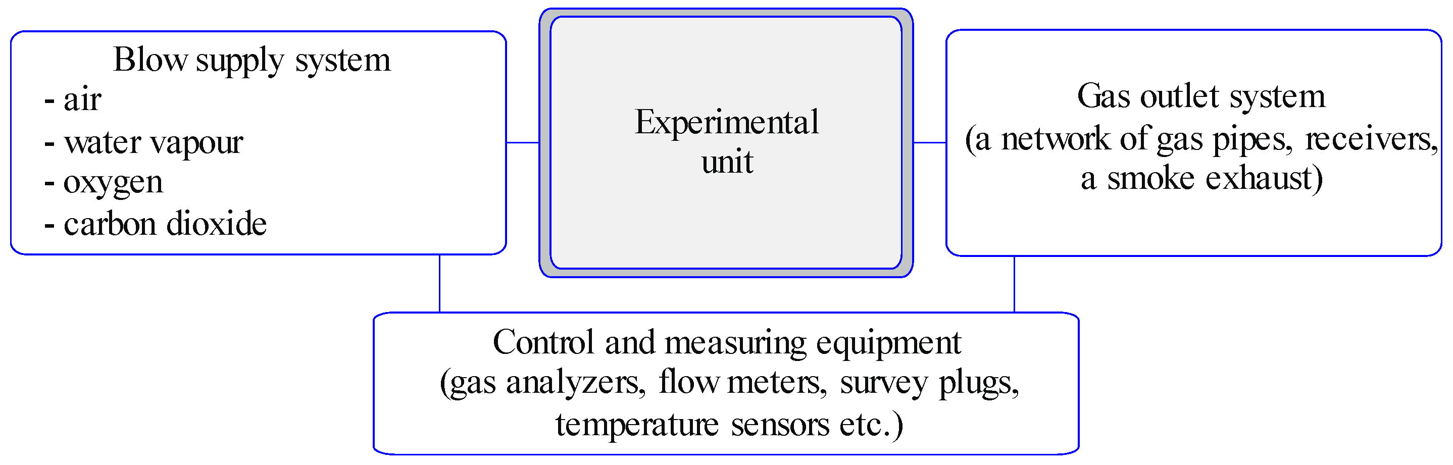
2.3.1. Experimental Stand Unit

The experimental stand unit is designed and patented at Dnipro University of Technology, and manufactured by Naftomash RMA under financial support of the Ministry of Education and Science of Ukraine.
A gas generator model consists of four systems (Figure 1):
An experimental stand;
A system of supply of separated and mixed blow mixture (blow reagents, see Section 2.3.3);
A gas outlet system;
A system of control and measuring equipment (temperature control and control of input and output gas mixtures).
An experimental stand welded from sheet steel is a central link of the facility. There are holes for blow supply and generator gas outlet as well as ignition and control holes on the stand front [90,91]. A system of thermal sensors with signal converters equipped with the interface was used to identify the temperature field parameters. The reference shear detectors were used to control the coal mass state.
The coal rock mass was modelled in terms of the experimental unit according to the similarity criteria (see Section 2.3.5).

2.3.2. Ultimate and Technical Composition of Coal

Hard coal (high volatile bituminous coal) was selected as the raw material to be gasified. That coal grade prevails in Ukrainian energy balance as it is represented by rather great reserves. Table 1 shows proximate and ultimate analysis of the coal.
The values shown in Table 1 are used to calculate the material and heat balance (see Section 2.3.4), being an indispensable part of research as the obtained results of calculations define the required amount of blow to be supplied into a gas generator.

2.3.3. Blow Reagents

The stand-based experimental studies were accompanied by changes in the parameters of blow reagents. Five basic previously tested blow types were used, i.e.:
  • Air blow (O2—21%, N2—79%);
  • Air–steam blow (O2—21%, N2—79%, H2Osteam);
  • Oxygen–steam blow (O2—35%, N2—65%, H2Osteam);
  • Oxygen–enriched blow (O2—35%, N2—65%);
  • Carbon dioxide and oxygen (O2—21%, CO2—10%, N2—69%).
A series of experimental studies was alternated by means of blow change. Each following change in blow mode was followed by the transfer to the air blow. A transition mode in terms of blow lasted one hour.

2.3.4. Material and Heat Balance

The material and heat balance are determined by physical rates of chemical reactions, technological efficiency of the process, and modes of blow mixture supply into the gasification zone [92]. To calculate the material and heat balance, the MT-Balance software was applied. The software product was developed at the Dnipro University of Technology [93,94].
During the calculation, the software uses not only the specified parameters of the ultimate and technical composition of the coal but also many physical values-constants as well as the values characterizing the initial state of the gasification process. The software algorithm makes it possible to obtain the following:
Material balance of the oxidizing zone;
Material balance of the reducing zone;
Volumetric parameters of gas mixtures of a gas generator;
Chemical and physical efficiency of the gasification process;
Energy balance of the gasification process;
Total energy of the oxidizing and reducing zones.
Identification of the material and heat balance with the help of underground gasification is a valid and convenient mechanism for obtaining quantitative and qualitative parameters of the blow mixture composition and gases outgoing from a gas generator. That allows simplifying considerably the data processing and helps obtain rapidly the final results with high degree of conformity.

2.3.5. Similarity Criteria

Modeling of the operating parameters of the process of underground coal gasification according to the criteria of similarity to field conditions are the important elements of the experimental data transfer into the field conditions as the performance of experiments in terms of ground stand units are aimed at simulation of the UCG processes taking into account geological and technological parameters [95,96].
The research was carried out in terms of the experimental stand unit to model a process of underground gasification taking into consideration the similarity criteria and the specified scale coefficients. Following expression is taken as the basis in terms of non-stationary seam gasification [97]:
T ¯ = T T 0 T max T 0 = f ( H 0 ) ,
where T is current temperature, °C; Tmax is maximum temperature, °C; T0 is initial temperature, °C; H0 is criterion of homochronicity (of time).
H 0 = v t x = 1 ,
where v is gasifying rate, m/day; t is gasifying time, days; x is distance, m.
Generally, all similarity criteria, taking into consideration time, are called homochronicity criteria (Ho) since they are applied to identify a time conversion factor through a multiplier of other physical quantities. Hence, in terms of similarity of two or more systems, Ho (homochronicity criterion), Fr (Froude number), Eu (Euler’s criterion), and Re (Reynolds number) have the same values for any similar points. In practice of similarity criteria use, it is expedient to reduce some of them to more convenient format helping determine directly values being a part of the criteria.
Thus, a conclusion concerning full nature-model similarity compliance makes it possible to calculate homochronicity criterion, i.e., constant temporal similarity within the processes. Comparison of modeling of working parameters of underground coal gasification helps obtain the following:
H o = v t x = v t x ,
where v is actual displacement velocity of a material point, m/day; t is displacement time of the point, days; x is distance passed by the material point during t time, m; and v , t , x are velocity, time, and path of a similar material point on the model, respectively.
To obtain the valid results of the modelling in terms of the experimental stand unit that would help get the data for field conditions, a group of similarity invariants, characterizing the gasification process, were considered [98]:
Kinetics of chemical reactions;
Gas dynamics and mass exchange of the oxidizing and reducing zones;
Convective and conductive heat exchange.
Adherence to the abovementioned similarity invariants, representing the gasification kinetics, was obtained by the fact that the coal model was of the same grade and composition as the “field” coal.
Convectional temperature exchange takes place right within a contact of reactional zone expanding up to 2–4 thicknesses of the degassed seam. Then, enthalpy takes place at the expense of conductive rock heating. Temperature rise and its expansion deep in the rock mass last until origination of thermal stresses varying rock behavior while falling [99]. Based upon previous research carried out under the conditions of Western Donbas mines, it can be concluded that convectional enthalpy transfer was observed at greater distances than 6 m [100]. This situation is justified by the stratification cavities formation in the roof of an underground gasifier and the presence of pores and fractures in it. The degree of influence of heat exchange convection is determined by the presence of cavities in the rocks and their location, which in turn determines the thermal stress of the adjacent roof rocks.
The pressure in the underground gas generator model and the ultimate composition of a generator gas in the similarity scale meet the field conditions. According to the calculated data, air consumption during the air blow was 2.32 m3/kg of coal; in case of blow enriched with oxygen, it was 1.89 m3/kg of coal. The reaction channel length within the experimental stand is 1.5 m; thickness of the coal seam is 0.5 m. Taking into account the similarity criteria, a 1.5 m value of the reaction channel length corresponds to the reaction channel length of the underground gas generator being 30 m.

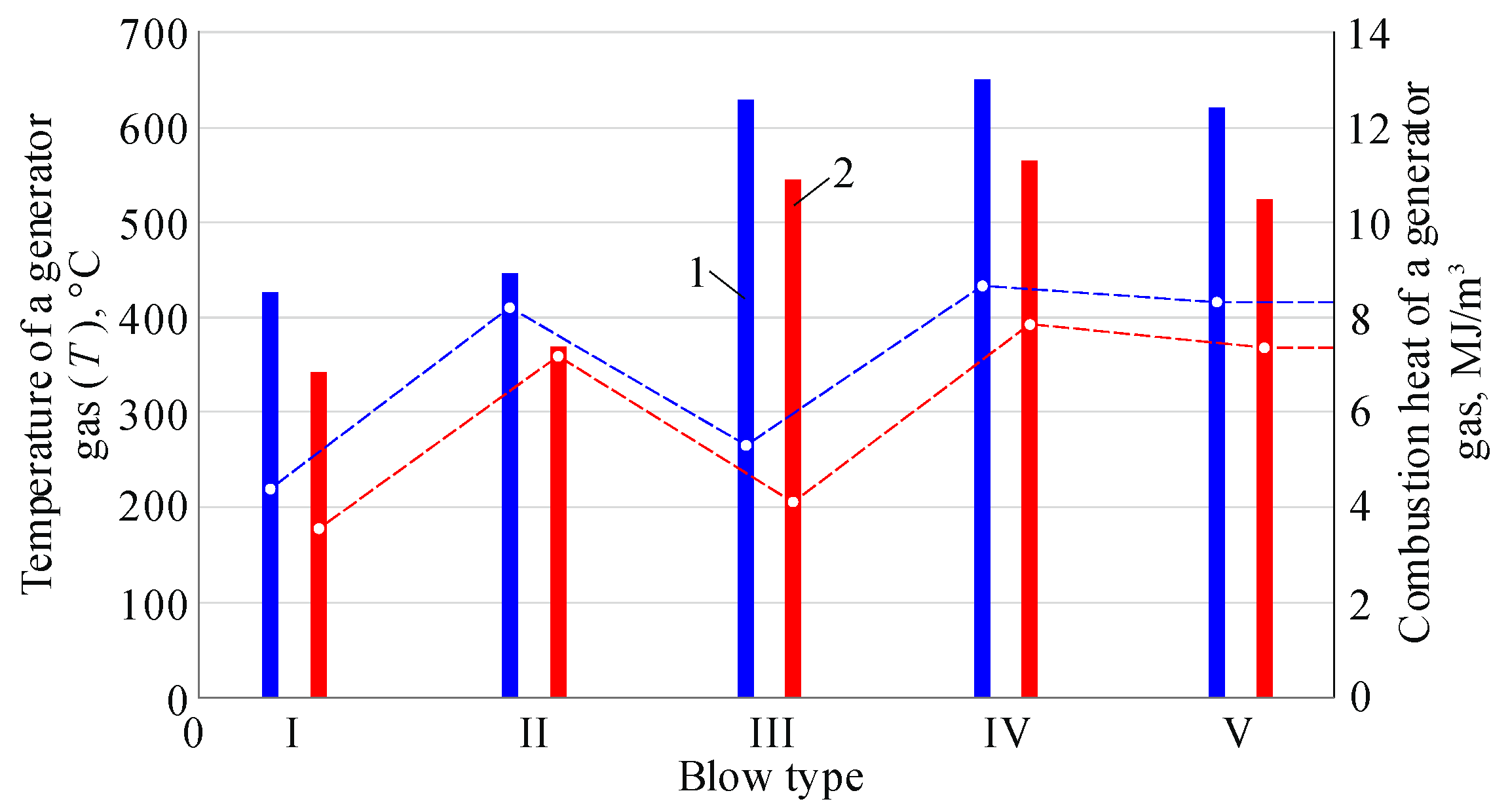
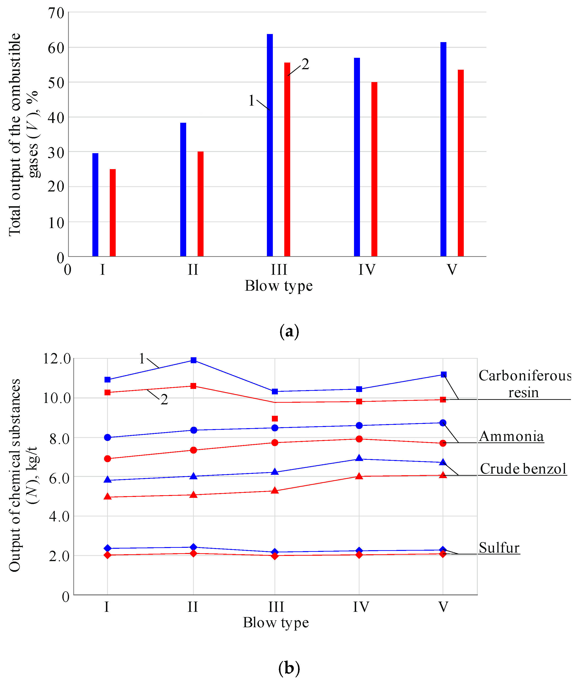
3. Results and Discussion

As a result of the stand-based experimental studies, the influence of tightness characteristics of a gas generator on the quantitative and qualitative parameters of coal seam gasification have been identified. Figure 2 demonstrates a graph of changes in losses of the blow supplied into a gas generator and the obtained generator gas in terms of changing pressure growth from 0 to 0.35 MPa.
The Graph demonstrates that stowing nonavailability starts impacting blow and generator gas losses in terms of minimum pressure change achieving maximum 32.5% values at 0.35 MPa pressure. In turn, at the same pressure value, stowing is only 15%. Hence, 17.5% (i.e., more than double) difference in blow losses has been identified depending upon various modes of preparation of gas generators.
A gas generator design with stowing of the deformed thickness of the roof rocks and gasified space is characterized by Kt.u.g/g = 0.032 coefficient of leak-tightness. At the same time, the tightness coefficient of a gas generator without stowing is Kt.u.g/g = 0.214.
In terms of sufficient gas generator tightness (Kt.u.g/g = 0.032), it is possible to ensure effective contact of blow and a combustion face of the reaction channel. In addition, heat capacity of the rocks enclosing a gas generator increases; heat efficiency of the reaction zones of a gas generator grows stipulating stability of material and heat balance of the coal seam gasification process.
Figure 3 shows the dependences of heat conductivity of the rocks around a gas generator on the temperatures emitting during gasification and tightness of a gas generator.
Increase in temperatures in the oxidizing zone of a gas generator and heat capacity of rock layers are observed throughout the reaction channel length, which is stipulated by heat losses in the rocks around the reaction channel. That happens at the expense of decreasing heat and temperature conductivity of the roof rocks. Heat-generating capacity of the oxidizing zone at the expense of artificial heat insulation of the rock mass provides efficient operation of the reducing zone, where endothermal reactions with heat absorption occur. Technogenic heat of the rock mass around a gas generator is rather considerable; correspondingly, in terms of its removal, it can be used in cogeneration plants.
Coal is gasified in terms of blow injection from the side of coal mass and gas removal from the gasified space. Along with the expanding degassed void, consumer features (calorific capacity) of gas are deteriorating as the gasification front is displacing gradually from the initial location to the gasification boundaries, leaving behind the gasified space, which is filled gradually with slugs, residual coal, and deposited rocks of the upper thickness. The fly ash is driven out of coal from an underground gasifier together with the generator gases. It is generally captured by particle filtration equipment before the flue gases reach the chimneys. Non-reacted coal ash is left in the mined-out space. The volume of non-reacted coal ash makes up 38–45% of the volume of the coal seam.
Figure 4 shows the results of analyzing the temperatures of gasification products at their output from the gas-outlet well and combustion heat of a generator gas of a thin carboniferous seam.
The obtained results of stand-based experimental studies of design features of artificial tightness of a gas generator have made it possible to evaluate the quantitative and qualitative parameters of the output of coal seam gasification products taking into account mining-geological conditions, design features of a gas generator, and technological parameters of the gasification process (Figure 5).
Decreasing natural and artificial fractures of the layered roof rock thickness and the gasified space at the expense of increased tightness of a gas generator helps reduce migration of high-temperature UCG products into the roof and floor rocks. In turn, that will allow further expansion of the UCG application area in terms of thin coal seams occurring at shallow depths. The calculations have shown that preparation of underground gas generators with injection stowing of the roof rocks will make it possible to increase the gasified coal area by 1.6–1.8 times, the degree of coal seam gasification will grow by 7–12%, and the heat-generation gas capacity will go up to 18%.
At the same time, great attention should be paid to continuous supply of air mixture onto the combustion face of the gas generator’s reaction channel as that creates stable pressure and activates heat-generation within the oxidizing zone of the reaction channel. That results in the balanced behavior of active zones of a gas generator and balanced kinetics of thermochemical reactions of the gasification process.
Having been developed and tested in terms a stand unit for simulation of the underground coal gasification process, the design and technical solutions aimed at blow supplying immediately onto the combustion face stipulate intensification of a gasification process of thin coal seams taking into account specific mining-geological conditions.
Consequently, three possible gas generator designs were to be analyzed as for the efficiency of a gasification process:
(1)
Without a flexible pipeline for blow direction onto the reaction channel face (design A);
(2)
With flexible pipelines for blow direction through perforated nozzles onto the reaction channel face (design B);
(3)
With flexible pipelines and activator in the reaction channel, with blow direction onto the reaction channel face (design C).
(4)
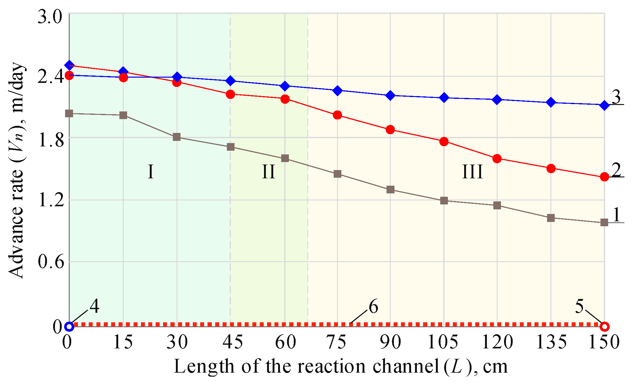
Figure 6 represents the results of a series of experiment studies.
If a gas blow flows from the side of mass, gas outlet towards the gasified space is stimulated somehow by large volumes of that space, deformation, and rock caving into the gasification zone as well as the available excessive pressure in it.
Coal is gasified better around the blow well than around the gas-outlet well. Thus, this is the point with higher concentration of coal losses in terms of seam area and thickness. Moreover, it is stipulated not only by the unilateral direction of the blow flow but also by the fact that the advance of reaction zones of gasification along the channel length is accompanied by the deteriorating aerodynamic conditions, and finally there will be a moment when there is no sufficient length for the reaction zones.
Figure 7 summarizes analyses of the effects of different designs of a gas generator (A, B, and C) as for the blow supply into the reaction channel on the uniformity of the combustion face advance.
While analyzing Figure 7, it is possible to state the following: if coal seam is gasified involving the gas generator design with flexible pipelines and activator in the reaction channel as well as the blow direction onto the combustion face of a reaction channel (design C), there is no need in blow reverse as we can observe uniform advance of the gas generator’s combustion face.
Involvement of the off-balance and abandoned reserves of thin and very thin coal seams into gasification in terms of using the designs and technological schemes of gas generators with the controlled flexible pipelines, perforated nozzles, and activators provides adaptive activation of the oxidizing and reducing processes with the controlled transition zone between them in the reaction channel of a gas generator. Control and controllability of a gas generator throughout the reaction channel length is ensured by the dosed, separate supply of a blow flow onto the combustion face into each active zone of the reaction channel. That results in the reduced losses of blow, generator gas, and solid fuel; it also stipulates uniform advance of active zones of the reaction channel’s combustion face during the coal seam gasification.
Implementation of the abovementioned technological solutions in the gas generator designs and technological solutions of coal seam gasification will reduce considerably the time spent for the formation of a reaction channel and beginning of the mine gas generator’s operation in active mode of coal gasification (Figure 8).
Consideration of geological structure, ultimate composition of a solid fuel, rocks of the roof and floor as well as the parameters of blow mode and its direction onto the combustion face according to the functional features of active zones of a reaction channel and design solutions of a gas generator stipulates adaptivity of the process of underground coal gasification to a concrete model of thin coal seam development in terms of using flexible pipes with perforated nozzles, or activator.
Control of the process of thin and very thin coal seam gasification with the help of flexible pipelines with blow direction through perforated nozzles onto the reaction channel face (scheme B) does not provide sufficiently effective activation of thermochemical processes within the active zones of a gas generator. In terms of oxidizing zone of the reaction channel, that design solution effects immediately the kinetics of chemical reactions and heat generation. The reducing zone is not affected immediately; thus, the reducing gasification processes proceed under the effect of gas products and heat generated within the oxidizing zone. Figure 8 demonstrates that design C helps reduce almost twofold the time for reaching the main processes, i.e., a gasification process experiences its intensification.
Disadvantages of the design are as follows: impossibility to control the oxidizing zone of a gas generator, nonuniform gasification of the combustion face of the reaction channel that influence negatively the quality of a thermochemical process as well as prolongs the time for preparation and formation of the reaction channel and reverse of blow flows.
Implementation of a perforated activator in the reaction channel of a gas generator to activate the underground coal gasification process ensures immediate effect on active zones of the combustion face; that helps control the active zones maintaining energy balance between the zones and selectivity of a gasification product, and increase quantitative and qualitative parameters of the process. Concerning disadvantages of design C, it can be mentioned that considerable mass of a perforated activator creates resistance during its displacement along with the advance of the gas generator’s combustion face. Consequently, critical loads are formed on a flexible pipeline and its connection with the activator causing the need in limitation of the length of the gas generator’s extraction pillar.
The obtained results of changes in generator gas output depending upon a blow type are correlated with a high convergence degree with earlier studies of underground coal gasification. Namely, numerous papers mention positive effect by oxygen-enriched blow [101,102,103,104] as well as oxygen and steam blow [104,105] on generator gas output indices. Essential effect by carbon dioxide blow has also been mentioned in [106,107,108]. Moreover, experimental results support confidently earlier studies with the use of similar coal [85]. No doubt, we cannot suggest full compliance of the research results since ultimate and technical analysis of the coal is not identical.
Comparative analysis of the results concerning blow stream reversing with studies by foreign researchers, described scrupulously in [109,110,111], prove the correctness of the selected tendency to intensify underground gasification process.
As for the comparison of the improved techniques, proposed by this paper, their effect on a gas formation process is incomparable with the similar studies. Nevertheless, we have propose to the studies alternative techniques of blow supply to fire mass of underground gas generator in addition to such popular systems as Controlled Retracting Injection Point (CRIP) [66,112,113], Movable Injection Point [114], Unfixed Pumping Points [115,116], and recently developed gasification agent injection tool for underground coal gasification [116].
The authors believe that further studies will concern analysis of underground gasification effect while degassing thin and very thin coal seams. Namely, determination of the influence of qualitative and quantitative composition of carbonous reagents on the gas formation efficiency within a reaction channel of an underground gas generator is meant. Moreover, a problem to analyze environmental component of a gasification process (among other things, formation of polluting gases and mercaptans and their expansion) remains a topical issue.

4. Conclusions

A series of experimental studies involving the gasification process modeling has helped substantiate the effect of technological and technical innovations in gas generator designs on the parameters of the coal seam gasification process.
Implementation of the designs of underground gas generators with stowing of the deformed roof rocks as well as the ones with the controlled active zones of a gas generator (especially while gasifying the abandoned balance and off-balance reserves of thin and very thin coal seams) provides adaptivity of the coal seam gasification process to specific mining-geological conditions.
A key feature of the innovative solutions of underground coal gasification, stipulating its economic expediency, is creation of favorable conditions for the directed blow supply into the reaction zone of coal mass from the variable points and keeps its contact with coal during the whole planned time of coal gasification.
Preparation of underground gas generators with injection stowing of the roof rocks will help reduce the prime cost of the produced coal by 23.5% owing to the following: area of the gasified coal increases by 1.6–1.8 times; degree of coal seam gasification grows by 7–12%. In this regard, maximum efficiency of underground gasification is achieved if a gas generator design involving flexible pipelines and activator in the reaction channel and blow direction onto the reaction channel face combined with blow stream reversing and oxygen blow use which will make it possible to improve caloricity of the generator gas up to 18% (i.e., from 8.4 to 12.8 MJ/m3 depending upon a blow type).
Design technological schemes allows controlling efficiently a gas-generation process by directed blow supply and constant forcing of a blow flow against the combustion bed surface by means of combination of gas-blow flows (blow injection and exhaustion of gasification products) and by reversing the blow flows.

Author Contributions

Conceptualization, V.L. and V.F.; methodology, V.L. and V.F.; software, P.S. and V.L.; validation, R.D. and E.C.; formal analysis, O.B. and P.S.; investigation, V.L. and V.F.; resources, P.S.; data curation, E.C.; writing—original draft preparation, V.L. and V.F.; writing—review and editing, R.D.; visualization, V.L. and P.S.; supervision, R.D.; project administration, O.B.; funding acquisition, O.B. All authors have read and agreed to the published version of the manuscript.

Funding

This study was carried out as part of the project “Belt and Road Initiative Institute for Chinese-European studies (BRIICES)” and was funded by the Guangdong University of Petrochemical Technology.

Institutional Review Board Statement

Not applicable.

Informed Consent Statement

Not applicable.

Data Availability Statement

Data are contained within the article.

Acknowledgments

The team of authors express their gratitude to the reviewers and editor for valuable recommendations that have been taken into account to improve significantly the quality of this paper. The research has been carried out in the framework of the implementation of projects “Synthesis, Optimization, and parametrization of the innovative technologies of the development of coal and gas deposit resources” (0119U000248) and “Geotechnological basics of the formation of energochemical complexes of coal-mining regions” (0120U102084).

Conflicts of Interest

The authors declare no conflict of interest.

References

  1. Kulikov, M.M.; Dulin, A.N.; Dulin, R.A. Prospects for Forming a Cluster for Deep Coal Processing in the Rostov Region. Smart Innov. Syst. Technol. 2019, 90–98. [Google Scholar] [CrossRef]
  2. Sekerin, V.; Dudin, M.; Gorokhova, A.; Bank, S.; Bank, O. Mineral resources and national economic security: Current features. Min. Miner. Depos. 2019, 13, 72–79. [Google Scholar] [CrossRef]
  3. Lishtvan, I.I.; Dudarchik, V.M.; Kraiko, V.M. Prospects for the deep processing of solid fossil fuels in Belarus. Solid Fuel Chem. 2017, 51, 267–272. [Google Scholar] [CrossRef]
  4. Tolmachev, O.; Urunov, A.; Muminova, S.; Dvoichenkova, G.; Davydov, I. Review of unconventional hydrocarbon resources:production technologies and opportunities for development. Min. Miner. Depos. 2020, 14, 113–121. [Google Scholar] [CrossRef]
  5. Bazaluk, O.; Havrysh, V.; Nitsenko, V.; Baležentis, T.; Streimikiene, D.; Tarkhanova, E.A. Assessment of Green Methanol Production Potential and Related Economic and Environmental Benefits: The Case of China. Energies 2020, 13, 3113. [Google Scholar] [CrossRef]
  6. Svyrydenko, D.; Mozgin, W. The Soft Power of the State as a Dialectic of Contemporary Dependencies in the International Arena. Ukrainian Policymaker 2019, 5, 89–97. [Google Scholar] [CrossRef] [PubMed]
  7. Sai, K.; Malanchuk, Z.; Petlovanyi, M.; Saik, P.; Lozynskyi, V. Research of Thermodynamic Conditions for Gas Hydrates Formation from Methane in the Coal Mines. Solid State Phenom. 2019, 291, 155–172. [Google Scholar] [CrossRef]
  8. Krichevskiy, S. Evolution of technologies, “green” development and grounds of the general theory of technologies. Philos. Cosmol. 2015, 14, 120–139. [Google Scholar]
  9. Haiko, H.; Saik, P.; Lozynskyi, V. The Philosophy of Mining: Historical Aspect and Future Prospect. Philos. Cosmol. 2019, 22, 76–90. [Google Scholar] [CrossRef]
  10. Fyk, M.; Biletskyi, V.; Abbood, M.; Al-Sultan, M.; Abbood, M.; Abdullatif, H.; Shapchenko, Y. Modeling of the lifting of a heat transfer agent in a geothermal well of a gas condensate deposit. Min. Miner. Depos. 2020, 14, 66–74. [Google Scholar] [CrossRef]
  11. Bazaluk, O.; Slabyi, O.; Vekeryk, V.; Velychkovych, A.; Ropyak, L.; Lozynskyi, V. A Technology of Hydrocarbon Fluid Production Intensification by Productive Stratum Drainage Zone Reaming. Energies 2021, 14, 3514. [Google Scholar] [CrossRef]
  12. Chen, C.; Horio, M.; Kojima, T. Numerical simulation of entrained flow coal gasifiers. Part I: Modeling of coal gasification in an entrained flow gasifier. Chem. Eng. Sci. 2000, 55, 3861–3874. [Google Scholar] [CrossRef]
  13. Goncharenko, L.; Ryzhakova, A.; Sedova, N.; Efimov, I.; Akulinin, F. Survey of the world practice of implementing energy-efficient technologies in terms of mining enterprises. Min. Miner. Depos. 2019, 13, 63–71. [Google Scholar] [CrossRef]
  14. Duan, T.; Lu, C.; Xiong, S.; Fu, Z.; Zhang, B. Evaluation method of the energy conversion efficiency of coal gasification and related applications. Int. J. Energy Res. 2015, 40, 168–180. [Google Scholar] [CrossRef]
  15. Bhutto, A.W.; Bazmi, A.A.; Zahedi, G. Underground coal gasification: From fundamentals to applications. Prog. Energy Combust. Sci. 2013, 39, 189–214. [Google Scholar] [CrossRef]
  16. Akbarzadeh Kasani, H.; Chalaturnyk, R.J. Coupled reservoir and geomechanical simulation for a deep underground coal gasification project. J. Nat. Gas Sci. Eng. 2017, 37, 487–501. [Google Scholar] [CrossRef]
  17. Nakaten, N.; Kempka, T. Techno-Economic Comparison of Onshore and Offshore Underground Coal Gasification End-Product Competitiveness. Energies 2019, 12, 3252. [Google Scholar] [CrossRef] [Green Version]
  18. Liu, H.; Liu, S. Life cycle energy consumption and GHG emissions of hydrogen production from underground coal gasification in comparison with surface coal gasification. Int. J. Hydrogen Energy 2021, 46, 9630–9643. [Google Scholar] [CrossRef]
  19. Shustov, O.; Pavlychenko, A.; Bondarenko, A.; Bielov, O.; Borysovska, O.; Abdiev, A. Substantiation into Parameters of Carbon Fuel Production Technology from Brown Coal. Mater. Sci. Forum 2021. Preprint. [Google Scholar]
  20. Shafirovich, E.; Varma, A. Underground Coal Gasification: A Brief Review of Current Status. Ind. Eng. Chem. Res. 2009, 48, 7865–7875. [Google Scholar] [CrossRef]
  21. Friedmann, S.J.; Upadhye, R.; Kong, F.-M. Prospects for underground coal gasification in carbon-constrained world. Energy Procedia 2009, 1, 4551–4557. [Google Scholar] [CrossRef] [Green Version]
  22. Kempka, T.; Plötz, M.-L.; Schlüter, R.; Hamann, J.; Deowan, S.A.; Azzam, R. Carbon dioxide utilisation for carbamide production by application of the coupled UCG-urea process. Energy Procedia 2011, 4, 2200–2205. [Google Scholar] [CrossRef] [Green Version]
  23. Buzylo, V.; Pavlychenko, A.; Savelieva, T.; Borysovska, O. Ecological aspects of managing the stressed-deformed state of the mountain massif during the development of multiple coal layers. E3S Web Conf. 2018, 60, 00013. [Google Scholar] [CrossRef] [Green Version]
  24. Medunić, G.; Mondol, D.; Rađenović, A.; Nazir, S. Review of the latest research on coal, environment, and clean technologies. Rud. Geol. Naft. Zb. 2018, 33, 13–21. [Google Scholar] [CrossRef]
  25. Novak, K.; Malvić, T.; Simon, K. Increased hydrocarbon recovery and CO2 management, a Croatian example. Environ. Earth Sci. 2012, 68, 1187–1197. [Google Scholar] [CrossRef]
  26. Popovych, V.; Telak, J.; Telak, O.; Malovanyy, M.; Yakovchuk, R.; Popovych, N. Migration of Hazardous Components of Municipal Landfill Leachates into the Environment. J. Ecol. Eng. 2020, 21, 52–62. [Google Scholar] [CrossRef]
  27. Menshov, O.; Sukhorada, A.; Homenko, R.; Kruglov, O. Ultradetailed Environmental Magnetic Investigations in Ukraine. Near Surf. Geosci. 2012, cp-306-00099. [Google Scholar] [CrossRef]
  28. Saik, P.; Petlevanyi, M.; Lozynskyi, V.; Sai, K.; Merzlikin, A. Innovative approach to the integrated use of energy resources of underground coal gasification. Solid State Phenom. 2018, 277, 221–231. [Google Scholar] [CrossRef]
  29. Bazaluk, O.; Sai, K.; Lozynskyi, V.; Petlovanyi, M.; Saik, P. Research into Dissociation Zones of Gas Hydrate Deposits with a Heterogeneous Structure in the Black Sea. Energies 2021, 14, 1345. [Google Scholar] [CrossRef]
  30. Sarhosis, V.; Kapusta, K.; Lavis, S. Underground coal gasification (UCG) in Europe: Field trials, laboratory experiments, and EU-funded projects. Undergr. Coal Gasif. Combust. 2018, 129–171. [Google Scholar] [CrossRef]
  31. Blinderman, M.S.; Klimenko, A.Y. Introduction to underground coal gasification and combustion. Undergr. Coal Gasif. Combust. 2018, 1–8. [Google Scholar] [CrossRef]
  32. Maev, S.; Blinderman, M.S.; Gruber, G.P. Underground coal gasification (UCG) to products: Designs, efficiencies, and economics. Undergr. Coal Gasif. Combust. 2018, 435–468. [Google Scholar] [CrossRef]
  33. Lozynskyi, V.; Medianyk, V.; Saik, P.; Rysbekov, K.; Demydov, M. Multivariance solutions for designing new levels of coal mines. Rud. Geol. Naft. Zb. 2020, 35, 23–32. [Google Scholar] [CrossRef]
  34. Motovilov, I.Y.; Telkov, S.A.; Barmenshinova, M.B.; Nurmanova, A.N. Examination of the preliminary gravity dressing influence on the Shalkiya deposit complex ore. Non Ferr. Met. 2019, 47, 3–8. [Google Scholar] [CrossRef]
  35. Gorova, A.; Pavlychenko, A.; Borysovs’ka, O. The study of ecological state of waste disposal areas of energy and mining companies. Annu. Sci. Tech. Colletion 2013, 169–172. [Google Scholar] [CrossRef]
  36. Nurpeisova, M.B.; Kurmanbaev, O.S. Laws of devolopment of geomechanical processes in the rock mass maykain mine. News Natl. Acad. Sci. Repub. Kazakhstan Ser. Geol. Tech. Sci. 2016, 6, 109–115. [Google Scholar]
  37. Dychkovskyi, R.; Shavarskyi, I.; Saik, P.; Lozynskyi, V.; Falshtynskyi, V.; Cabana, E. Research into stress-strain state of the rock mass condition in the process of the operation of double-unit longwalls. Min. Miner. Depos. 2020, 14, 85–94. [Google Scholar] [CrossRef]
  38. Babets, D.V.; Sdvyzhkova, O.O.; Larionov, M.H.; Tereshchuk, R.M. Estimation of rock mass stability based on probability approach and rating systems. Nauk. Visnyk Natsionalnoho Hirnychoho Universytetu 2017, 2, 58–64. [Google Scholar]
  39. Petlovanyi, M.; Lozynskyi, V.; Zubko, S.; Saik, P.; Sai, K. The influence of geology and ore deposit occurrence conditions on dilution indicators of extracted reserves. Rud. Geol. Naft. Zb. 2019, 34, 83–91. [Google Scholar] [CrossRef] [Green Version]
  40. Zeynullin, A.A.; Abeuov, E.A.; Demin, V.F.; Aliev, S.B.; Kaynazarova, A.S.; Kaynazarov, A.S. Estimation of ways to maintain mining works based on the application of anchor anchoring in the mines of the Karaganda coal basin. Ugol 2021, 2, 4–9. [Google Scholar] [CrossRef]
  41. Kyrgizbayeva, G.; Nurpeisov, M.; Sarybayev, O. The monitoring of earth surface displacements during the subsoil development. New Dev. Min. Eng. 2015, 161–167. [Google Scholar] [CrossRef]
  42. Kolokolov, O.V.; Tabachenko, M.M.; Eyshinskiy, O.M.; Kuznetsov, V.G.; Kablanov, A.I.; Mikenberg, O.A. Teoriya I Praktika Termohimichnoii Tehnologiii Vidobutku ta Pererobki Vugillya; NMA: Dnipro, Ukraine, 2000; 281p. [Google Scholar]
  43. Petlovanyi, M.; Lozynskyi, V.; Saik, P.; Sai, K. Predicting the producing well stability in the place of its curving at the underground coal seams gasification. E3S Web Conf. 2019, 123, 01019. [Google Scholar] [CrossRef] [Green Version]
  44. Dubiński, J.; Turek, M. Basic Aspects of Productivity of Underground Coal Gasification Process. Arch. Min. Sci. 2015, 60, 443–453. [Google Scholar] [CrossRef] [Green Version]
  45. Zou, C.; Chen, Y.; Kong, L.; Sun, F.; Chen, S.; Dong, Z. Underground coal gasification and its strategic significance to the development of natural gas industry in China. Pet. Explor. Dev. 2019, 46, 205–215. [Google Scholar] [CrossRef]
  46. Imran, M.; Kumar, D.; Kumar, N.; Qayyum, A.; Saeed, A.; Bhatti, M.S. Environmental concerns of underground coal gasification. Renew. Sustain. Energy Rev. 2014, 31, 600–610. [Google Scholar] [CrossRef]
  47. Mao, F. Underground coal gasification (UCG): A new trend of supply-side economics of fossil fuels. Nat. Gas Ind. B 2016, 3, 312–322. [Google Scholar] [CrossRef]
  48. Sobczyk, E.J.; Wota, A.; Kopacz, M.; Frączek, J. Clean Coal Technologies–a chance for Poland’s energy security. Decision-making using AHP with Benefits, Opportunities, Costs and Risk Analysis. Gospod. Surowcami Miner. 2017, 33, 27–48. [Google Scholar] [CrossRef] [Green Version]
  49. Yang, L. Clean coal technology—Study on the pilot project experiment of underground coal gasification. Energy 2003, 28, 1445–1460. [Google Scholar] [CrossRef]
  50. Prabu, V.; Jayanti, S. Integration of underground coal gasification with a solid oxide fuel cell system for clean coal utilization. Int. J. Hydrogen Energy 2012, 37, 1677–1688. [Google Scholar] [CrossRef]
  51. Khadse, A.; Qayyumi, M.; Mahajani, S.; Aghalayam, P. Underground coal gasification: A new clean coal utilization technique for India. Energy 2007, 32, 2061–2071. [Google Scholar] [CrossRef]
  52. Xie, J.; Xin, L.; Hu, X.; Cheng, W.; Liu, W.; Wang, Z. Technical application of safety and cleaner production technology by underground coal gasification in China. J. Clean. Prod. 2020, 250, 119487. [Google Scholar] [CrossRef]
  53. Dychkovskyi, R.; Vladyko, O.; Maltsev, D.; Cabana, E.C. Some aspects of the compatibility of mineral mining technologies. Rud. Geol. Naft. Zb. 2018, 33, 73–82. [Google Scholar] [CrossRef] [Green Version]
  54. Gayko, G.; Kasyanov, V. Utilizing Thermal Power Potential of Coal by Underground Burning (Gasification) of Thin Coal Layers. Int. Min. Forum 2007, 97–101. [Google Scholar] [CrossRef]
  55. Hu, Z.; Peng, Y.; Sun, F.; Chen, S.; Zhou, Y. Thermodynamic equilibrium simulation on the synthesis gas composition in the context of underground coal gasification. Fuel 2021, 293, 120462. [Google Scholar] [CrossRef]
  56. Małkowski, P.; Niedbalski, Z.; Hydzik-Wiśniewska, J. The Change of Structural and Thermal Properties of Rocks Exposed to High Temperatures in the Vicinity of Designed Geo-Reactor. Arch. Min. Sci. 2013, 58, 465–480. [Google Scholar]
  57. Wang, J.; Wang, Z.; Xin, L.; Xu, Z.; Gui, J.; Lu, X. Temperature field distribution and parametric study in underground coal gasification stope. Int. J. Therm. Sci. 2017, 111, 66–77. [Google Scholar] [CrossRef]
  58. Kapusta, K.; Stańczyk, K.; Wiatowski, M.; Chećko, J. Environmental aspects of a field-scale underground coal gasification trial in a shallow coal seam at the Experimental Mine Barbara in Poland. Fuel 2013, 113, 196–208. [Google Scholar] [CrossRef]
  59. Wiatowski, M.; Kapusta, K. Evolution of tar compounds in raw gas from a pilot-scale underground coal gasification (UCG) trial at Wieczorek mine in Poland. Fuel 2020, 276, 118070. [Google Scholar] [CrossRef]
  60. Laciak, M.; Kostúr, K.; Durdán, M.; Kačur, J.; Flegner, P. The analysis of the underground coal gasification in experimental equipment. Energy 2016, 114, 332–343. [Google Scholar] [CrossRef] [Green Version]
  61. Mocek, P.; Pieszczek, M.; Świądrowski, J.; Kapusta, K.; Wiatowski, M.; Stańczyk, K. Pilot-scale underground coal gasification (UCG) experiment in an operating Mine “Wieczorek” in Poland. Energy 2016, 111, 313–321. [Google Scholar] [CrossRef]
  62. Su, F.Q.; Itakura, K.; Hamanaka, A.; Deguchi, G.; Sato, K.; Kodama, J. Ex Situ UCG Model Experiments with Oxygen Enriched Air in an Artificial Coal Seam. Key Eng. Mater. 2017, 737, 379–384. [Google Scholar] [CrossRef]
  63. Doucet, D.; Perkins, G.; Ulbrich, A.; du Toit, E. Production of power using underground coal gasification. Energy Sources Part A Recovery Util. Environ. Eff. 2016, 38, 3653–3660. [Google Scholar] [CrossRef]
  64. Pivnyak, G.; Dychkovskyi, R.; Bobyliov, O.; Cabana, E.C.; Smoliński, A. Mathematical and Geomechanical Model in Physical and Chemical Processes of Underground Coal Gasification. Solid State Phenom. 2018, 277, 1–16. [Google Scholar] [CrossRef]
  65. Stańczyk, K.; Howaniec, N.; Smoliński, A.; Świądrowski, J.; Kapusta, K.; Wiatowski, M.; Rogut, J. Gasification of lignite and hard coal with air and oxygen enriched air in a pilot scale ex situ reactor for underground gasification. Fuel 2011, 90, 1953–1962. [Google Scholar] [CrossRef]
  66. Seifi, M.; Chen, Z.; Abedi, J. Numerical simulation of underground coal gasification using the CRIP method. Can. J. Chem. Eng. 2011, 89, 1528–1535. [Google Scholar] [CrossRef]
  67. Li, H.; Zha, J.; Guo, G.; Zheng, N.; Gong, Y. Improvement of resource recovery rate for underground coal gasification through the gasifier size management. J. Clean. Prod. 2020, 259, 120911. [Google Scholar] [CrossRef]
  68. Uwaoma, R.C.; Strydom, C.A.; Matjie, R.H.; Bunt, J.R.; van Dyk, J. The influence of the roof and floor geological structures on the ash composition produced from coal at UCG temperatures. Int. J. Coal Prep. Util. 2018, 40, 247–265. [Google Scholar] [CrossRef]
  69. Falshtynskyi, V.; Saik, P.; Lozynskyi, V.; Dychkovskyi, R.; Petlovanyi, M. Innovative aspects of underground coal gasification technology in mine conditions. Min. Miner. Depos. 2018, 12, 68–75. [Google Scholar] [CrossRef]
  70. Li, H.; Guo, G.; Zheng, N. Influence of coal types on overlying strata movement and deformation in underground coal gasification without shaft and prediction method of surface subsidence. Process Saf. Environ. Prot. 2018, 120, 302–312. [Google Scholar] [CrossRef]
  71. An, N.; Zagorščak, R.; Thomas, H.R.; Gao, W. A numerical investigation into the environmental impact of underground coal gasification technology based on a coupled thermal-hydro-chemical model. J. Clean. Prod. 2021, 290, 125181. [Google Scholar] [CrossRef]
  72. Róg, L. Vitrinite reflectance as a measure of the range of influence of the temperature of a georeactor on rock mass during underground coal gasification. Fuel 2018, 224, 94–100. [Google Scholar] [CrossRef]
  73. Kostúr, K.; Laciak, M.; Durdan, M. Some Influences of Underground Coal Gasification on the Environment. Sustainability 2018, 10, 1512. [Google Scholar] [CrossRef] [Green Version]
  74. Dvornikova, E.V. Environmental performance of underground coal gasification. Undergr. Coal Gasif. Combust. 2018, 363–399. [Google Scholar] [CrossRef]
  75. Shahbazi, M.; Najafi, M.; Marji, M.F. On the mitigating environmental aspects of a vertical well in underground coal gasification method. Mitig. Adapt. Strateg. Glob. Chang. 2019, 24, 373–398. [Google Scholar] [CrossRef]
  76. Burchart-Korol, D.; Krawczyk, P.; Czaplicka-Kolarz, K.; Smoliński, A. Eco-efficiency of underground coal gasification (UCG) for electricity production. Fuel 2016, 173, 239–246. [Google Scholar] [CrossRef]
  77. Wang, G.X.; Wang, Z.T.; Feng, B.; Rudolph, V.; Jiao, J.L. Semi-industrial tests on enhanced underground coal gasification at Zhong-Liang-Shan coal mine. Asia Pac. J. Chem. Eng. 2009, 45, 771–779. [Google Scholar] [CrossRef]
  78. Saik, P.B.; Dychkovskyi, R.O.; Lozynskyi, V.H.; Malanchuk, Z.R.; Malanchuk, Y.Z. Revisiting the underground gasification of coal reserves from contiguous seams. Nauk. Visnyk Natsionalnoho Hirnychoho Universytetu 2016, 6, 60–66. [Google Scholar]
  79. Zhu, L.; Wang, F.; Zhang, Z. Thermodynamic evaluation of a conceptual process for coal gasification coupled with chemical looping air separation. Chem. Eng. Process. Process Intensif. 2016, 106, 33–41. [Google Scholar] [CrossRef]
  80. Koroviaka, Y.; Pinka, J.; Tymchenko, S.; Rastsvietaiev, V.; Astakhov, V.; Dmytruk, O. Elaborating a scheme for mine methane capturing while developing coal gas seams. Rozrobka Rodovyshch 2020, 14, 21–27. [Google Scholar] [CrossRef]
  81. Yang, L. Coal Properties and System Operating Parameters for Underground Coal Gasification. Energy Sources Part A Recovery Util. Environ. Eff. 2008, 30, 516–528. [Google Scholar] [CrossRef]
  82. Lazarenko, S.N.; Kochetkov, V.N. The underground coal gasification is the technology which answers to conditions of sustainable development of coal region. Mine Plan. Equip. Sel. 2020, 167–168. [Google Scholar] [CrossRef]
  83. Falshtynskyi, V.; Lozynskyi, V.; Saik, P.; Dychkovskyi, R.; Tabachenko, M. Substantiating parameters of stratification cavities formation in the roof rocks during underground coal gasification. Min. Miner. Depos. 2016, 10, 16–24. [Google Scholar] [CrossRef] [Green Version]
  84. Majkherchik, T.; Gajko, G.I.; Malkowski, P. Deformation process around a heading investigation when front of longwall face advancing. Ugol 2002, 11, 27–29. [Google Scholar]
  85. Falshtynskyi, V.S.; Dychkovskyi, R.O.; Lozynskyi, V.G.; Saik, P.B. Determination of the Technological Parameters of Borehole Underground Coal Gasification for Thin Coal Seams. J. Sustain. Min. 2013, 12, 8–16. [Google Scholar] [CrossRef] [Green Version]
  86. Prusek, S.; Lubosik, Z.; Rajwa, S.; Walentek, A.; Wrana, A. Geotechnical monitoring of rock mass and support behaviour around the UCG georeactor: Two case studies in Polish coal mining industry. In Proceedings of the International Conference on Ground Control in Mining, Hangzhou, China, 27–29 October 2017; pp. 321–328. [Google Scholar]
  87. Bondarenko, V.; Dychkovskiy, R.; Falshtynskiy, V. Synthetic Stowing of Rockmass at Borehole Underground Coal Gasification (BUCG). Deep Min. Chall. 2009, 169–177. [Google Scholar] [CrossRef]
  88. Buzylo, V.; Bondarenko, V.; Dychkovskiy, R.; Falshtynskiy, V. Parameters of Injection Fill above an Underground Gas Generator. Technical, Technological and Economical Aspects of Thin-Seams Coal Mining. Int. Min. Forum 2007, 89–95. [Google Scholar] [CrossRef]
  89. Falshtynskyi, V.; Dychkovskyi, R.; Saik, P.; Lozynskyi, V. Someaspectsoftechnologicalprocessescontrolofanin-situgasifierduringcoalseamgasification. In Progressive Technologies of Coal, Coalbed Methane, and Ores Mining; CRC Press: London, UK, 2014; pp. 109–112. [Google Scholar] [CrossRef]
  90. Saik, P.; Lozynskyi, V.; Chemeriachko, Y.; Cabana, E. Basics of the approach formation to substantiate the temperature field distribution during experimental research on the coal gasification processes. E3S Web Conf. 2020, 202, 01037. [Google Scholar] [CrossRef]
  91. Falshtynskyi, V.; Dychkovskyi, V.; Lozynskyi, V.; Saik, P. New method for justification the technological parameters of coal gasification in the test setting. Geomech. Process. Dur. Undergr. Min. Proc. Sch. Undergr. Min. 2012, 201–208. [Google Scholar] [CrossRef]
  92. Durdán, M.; Terpák, J.; Kačur, J.; Laciak, M.; Flegner, P. Modeling of material balance from the experimental UCG. Acta Polytech. 2020, 60, 391–399. [Google Scholar] [CrossRef]
  93. Lozynskyi, V.; Dychkovskyi, R.; Saik, P.; Falshtynskyi, V. Coal Seam Gasification in Faulting Zones (Heat and Mass Balance Study). Solid State Phenom. 2018, 277, 66–79. [Google Scholar] [CrossRef]
  94. Lozynskyi, V.; Saik, P.; Petlovanyi, M.; Sai, K.; Malanchuk, Z.; Malanchyk, Y. Substantiation into mass and heat balance for underground coal gasification in faulting zones. Inz. Miner. 2018, 19, 289–300. [Google Scholar] [CrossRef]
  95. Uciechowska-Grakowicz, A.; Strzelecki, T. Application of the thermoporoelasticity model in numerical modelling of underground coal gasification influence on the surrounding medium. Studia Geotech. Et Mech. 2021. in Press. [Google Scholar] [CrossRef]
  96. Janoszek, T.; Stańczyk, K.; Smoliński, A. Modelling Test of Autothermal Gasification Process Using CFD. Arch. Min. Sci. 2017, 62, 253–268. [Google Scholar] [CrossRef] [Green Version]
  97. Lozynskyi, V.H. Substantiation into Parameters of Borehole Underground Coal Gasification Technology in the Faulting Zone; National Mining University (Dnipro University of Technology): Dnipro, Ukraine, 2015; pp. 1–156. [Google Scholar]
  98. Pivnyak, G. Conditions of Suitability of Coal Seams for Underground Coal Gasification. Key Eng. Mater. 2020, 844, 38–48. [Google Scholar] [CrossRef]
  99. Savostianov, O.V. Matematychna model napryzhenno-deformovanoho stanu porodnoho masyvy pry pidzemnii hazyfikacii tverdoho palyva. Collect. Res. Pap. Natl. Min. Univ. 2008, 30, 44–56. [Google Scholar]
  100. Falshtynskyi, V.; Dychkovskyi, R.; Illiashov, M. Engineering support of BUCG process in Solenovsk coal deposits. Tech. Geoinf. Syst. Min. 2011, 47–56. [Google Scholar] [CrossRef]
  101. Hongtao, L.; Feng, C.; Xia, P.; Kai, Y.; Shuqin, L. Method of oxygen-enriched two-stage underground coal gasification. Min. Sci. Technol. 2011, 21, 191–196. [Google Scholar] [CrossRef]
  102. Yang, L.H.; Zhang, X.; Liu, S. Underground Coal Gasification Using Oxygen and Steam. Energy Sources Part A Recovery Util. Environ. Eff. 2009, 31, 1883–1892. [Google Scholar] [CrossRef]
  103. Eftekhari, A.A.; Wolf, K.H.; Rogut, J.; Bruining, H. Energy and exergy analysis of alternating injection of oxygen and steam in the low emission underground gasification of deep thin coal. Appl. Energy 2017, 208, 62–71. [Google Scholar] [CrossRef] [Green Version]
  104. Liu, S.; Liang, J.; Chang, J.; Yang, Z.; Yu, L. UCG model test of Huating coal with oxygen-steam as gasification agent. J. Southeast Univ. 2003, 33, 355–358. [Google Scholar]
  105. Sadasivam, S.; Zagorščak, R.; Thomas, H.R.; Kapusta, K.; Stańczyk, K. Experimental study of methane-oriented gasification of semi-anthracite and bituminous coals using oxygen and steam in the context of underground coal gasification (UCG): Effects of pressure, temperature, gasification reactant supply rates and coal rank. Fuel 2020, 268, 117330. [Google Scholar] [CrossRef]
  106. Marcourt, M.; Paquay, V.; Piel, A.; Pirard, J.-P. Coal gasification at pressure by mixtures of carbon dioxide and oxygen. Fuel 1983, 62, 823–828. [Google Scholar] [CrossRef]
  107. Chodankar, C.R.; Feng, B.; Ran, J.; Klimenko, A.Y. Kinetic study of the gasification of chinchilla coal char in carbon dioxide. Annu. Int. Pittsburgh Coal Conf. 2007, 3, 1280–1291. [Google Scholar]
  108. Jayaraman, K.; Gokalp, I. Effect of char generation method on steam, CO2 and blended mixture gasification of high ash Turkish coals. Fuel 2015, 153, 320–327. [Google Scholar] [CrossRef] [Green Version]
  109. Liu, H.; Chen, F.; Wang, Y.; Liu, G.; Yao, H.; Liu, S. Experimental Study of Reverse Underground Coal Gasification. Energies 2018, 11, 2949. [Google Scholar] [CrossRef] [Green Version]
  110. Cui, Y.; Liang, J.; Wang, Z.; Zhang, X.; Fan, C.; Liang, D.; Wang, X. Forward and reverse combustion gasification of coal with production of high-quality syngas in a simulated pilot system for in situ gasification. Appl. Energy 2014, 131, 9–19. [Google Scholar] [CrossRef]
  111. Cui, Y.; Liang, J.; Wang, Z.; Zhang, X.; Fan, C.; Wang, X. Experimental forward and reverse in situ combustion gasification of lignite with production of hydrogen-rich syngas. Int. J. Coal Sci. Technol. 2014, 1, 70–80. [Google Scholar] [CrossRef] [Green Version]
  112. Elahi, S.M.; Nassir, M.; Chen, Z. Effect of various coal constitutive models on coupled thermo-mechanical modeling of underground coal gasification. J. Pet. Sci. Eng. 2017, 154, 469–478. [Google Scholar] [CrossRef]
  113. Perkins, G. Underground coal gasification–Part I: Field demonstrations and process performance. Prog. Energy Combust. Sci. 2018, 67, 158–187. [Google Scholar] [CrossRef]
  114. Kashyap, S.; Vairakannu, P. Movable injection point–based syngas production in the context of underground coal gasification. Int. J. Energy Res. 2020, 44, 3574–3586. [Google Scholar] [CrossRef]
  115. Yang, L. Study on the Method of Two-Phase Underground Coal Gasification with Unfixed Pumping Points. Energy Sour. 2003, 25, 917–930. [Google Scholar] [CrossRef]
  116. Chen, Z.; Zhu, F.; Zhang, Y.; Lv, W.; Zhang, Z. Development of gasification agent injection tool for underground coal gasification. E3S Web Conf. 2021, 267, 02056. [Google Scholar] [CrossRef]
Figure 1. Technological scheme of a stand unit of underground coal gasification.
Energies 14 04369 g001
Figure 2. Dependence of blow and gas losses (P, %) in terms of pressure changes in an underground gas generator: 1—gas generator design with stowing of the deformed thickness of the roof rocks and gasified space; 2—gas generator design without stowing.
Energies 14 04369 g002
Figure 3. Dependences of heat conductivity of the rocks (λ) around a gas generator on the temperatures emitting during gasification and tightness of a gas generator: (a)—general conductivity of the roof rocks of a gas generator; (b)—heat conductivity of the roof rocks along the combustion face of a gas generator; 1—generator design with stowing of the deformed thickness of the roof rocks and gasified space; 2—generator design without stowing; 3—air-supply well; 4—gas-outlet well; 5—line of the combustion face of a gas generator; I—oxidizing zone; II—transition zone; III—reducing zone.
Energies 14 04369 g003
Figure 4. Dependence of changes in the temperature of coal gasification products (generator gas) at their output from a gas-outlet well and combustion heat of a generator gas upon the blow type and tightness of a gas generator: 1—generator design with stowing of the deformed thickness of the roof rocks and gasified space; 2—generator design without stowing; I—air blow (O2—21%, N2—79%); II—air-steam blow (O2—21%, N2—79%, H2Osteam); III—oxygen-steam blow (O2—35%, N2—65%, H2Osteam); IV—oxygen-enriched (O2—35%, N2—65%); V—carbon dioxide and oxygen (O2—21%, CO2—10%, N2—69%).
Energies 14 04369 g004
Figure 5. Dependences of changes in the output of coal gasification products (generator gas) upon the blow type and tightness of a gas generator: (a)—output of combustible gases; (b)—output of chemical substances from a condensate; 1—generator design with stowing of the deformed thickness of the roof rocks and gasified space; 2—generator design without stowing; I—air blow (O2—21%, N2—79%); II—air-steam blow (O2—21%, N2—79%, H2Osteam); III—oxygen-steam blow (O2—35%, N2—65%, H2Osteam); IV—oxygen-enriched (O2—35%, N2—65%); V—carbon dioxide and oxygen (O2—21%, CO2—10%, N2—69%).
Energies 14 04369 g005
Figure 6. Dependences of the losses of blow, generator gas, and coal upon the gas generator design: 1—design A; 2—design B; 3—design C; 4—air-supply well, 5—gas-outlet well, 6–line of the combustion face of a gas generator; I—oxidizing zone; II—transition zone; III—reducing zone.
Energies 14 04369 g006
Figure 7. Dependences of the effect of different designs of blow supply into the gas generator’s reaction channel on the uniform combustion channel advance depending on the gas generator design: 1—design A; 2—design B; 3—design C; 4—air-supply well, 5—gas-outlet well, 6—line of the combustion face of a gas generator; I—oxidizing zone; II—transition zone; III—reducing zone.
Energies 14 04369 g007
Figure 8. Effect of the gas generator design on the time of achieving the main processes: a—formation of the reaction channel of a gas generator; b—start of the gasification mode of a gas generator; c—reversing; 1—design A; 2—design B; 3—design C.
Energies 14 04369 g008
Table 1. Proximate and ultimate analysis of the coal.
Proximate AnalysisUltimate AnalysisCombustion Heat (Qr), MJ/kgCoal Density (γ), g/cm3
Wr, %Wa, %Ac, %Sd, %Vdaf, %Cdaf, %Hdaf, %Odaf, %Nr, %
1.72.238.21.337.080.76.36.84.924.61.45
Publisher’s Note: MDPI stays neutral with regard to jurisdictional claims in published maps and institutional affiliations.

