
Investigations of Flow and Heat Transfer Characteristics in a Channel Impingement Cooling Configuration with a Single Row of Water Jets


Abstract
:1. Introduction
2. Experimental Method
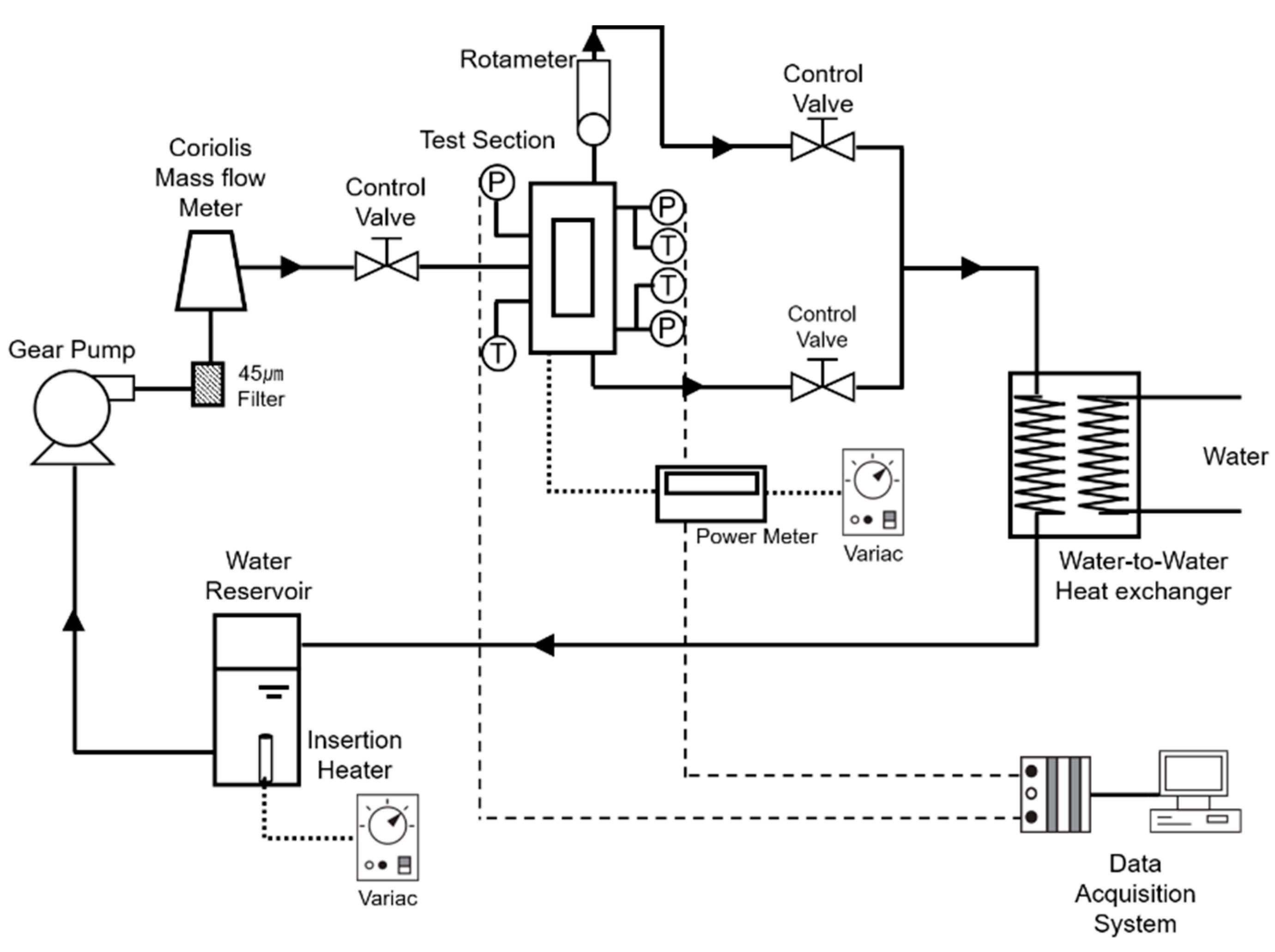
2.1. Flow Loop
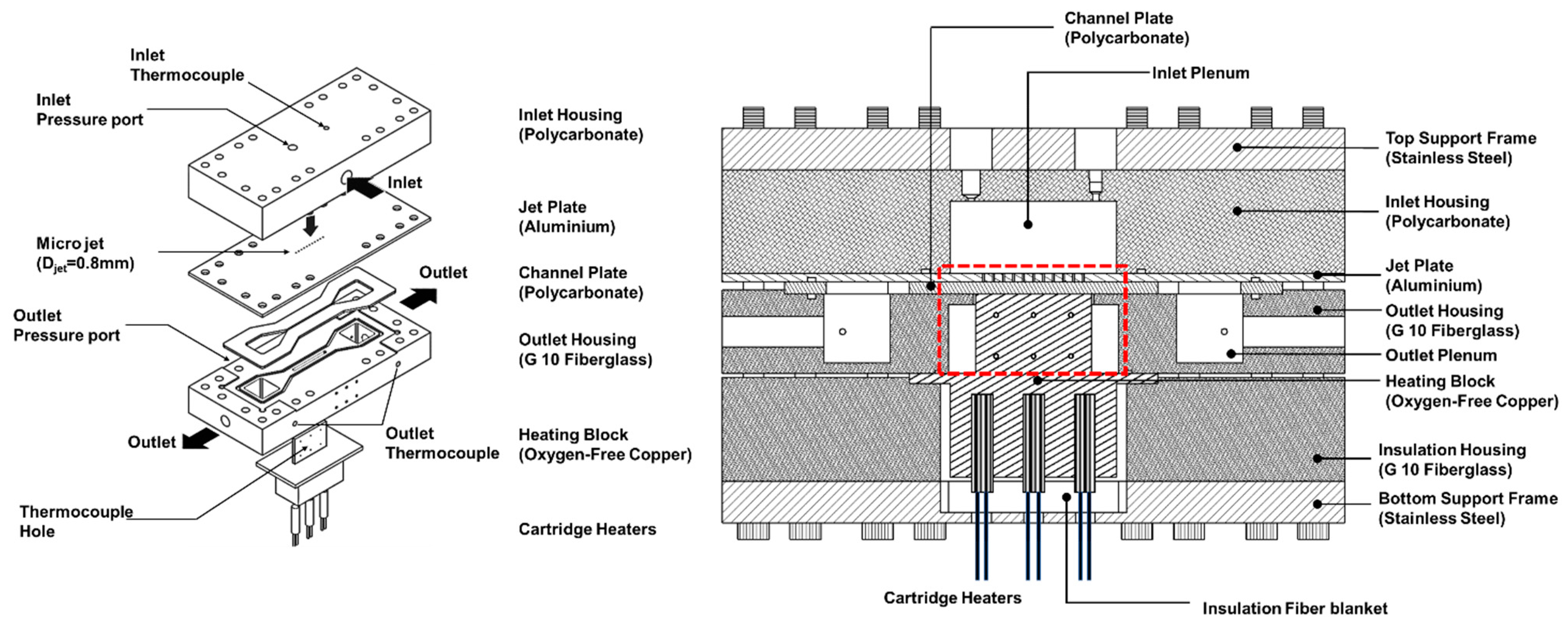
2.2. Test Module
2.3. Operating Procedure
2.4. Measurement Uncertainty
3. Numerical Model
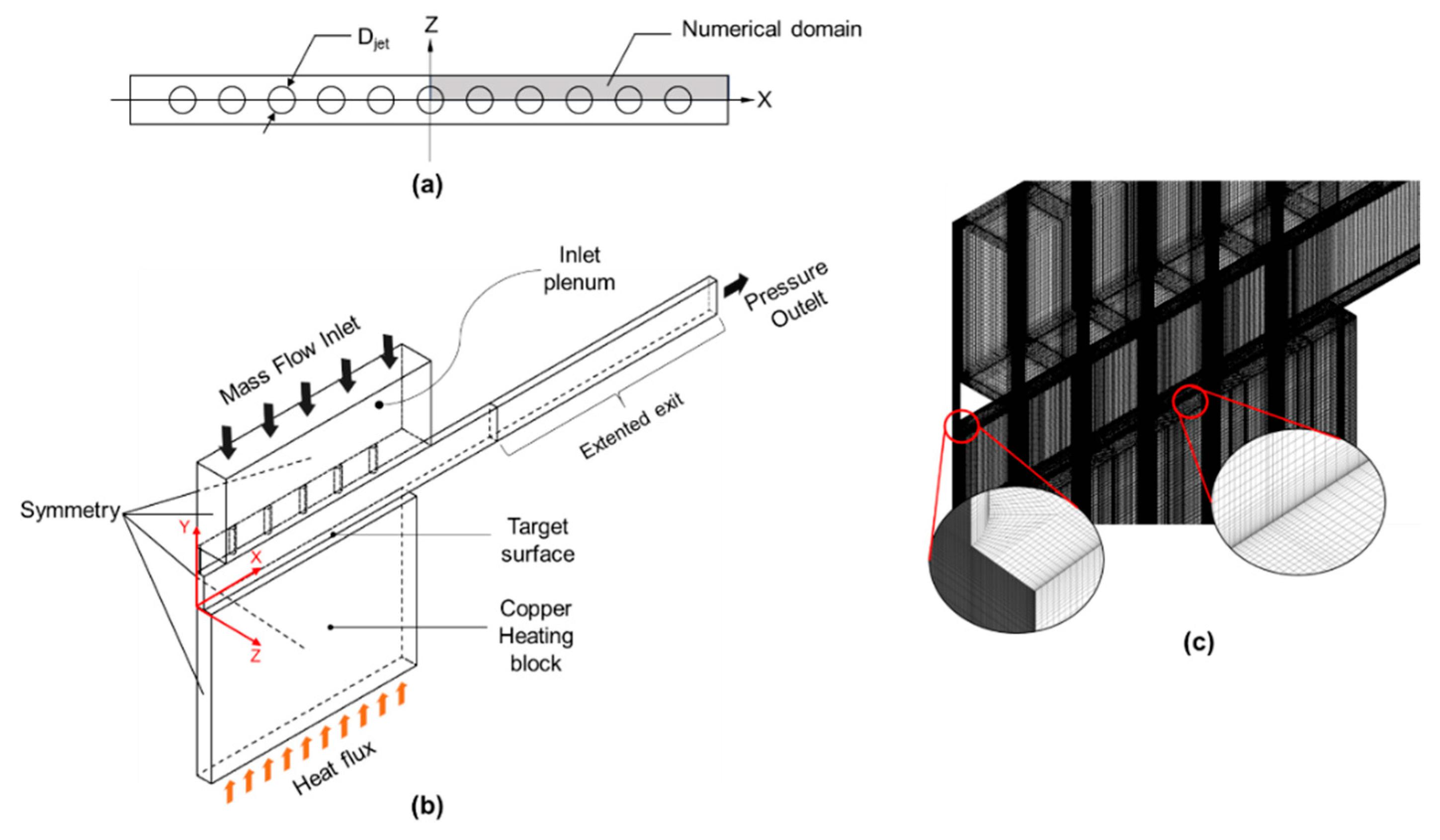
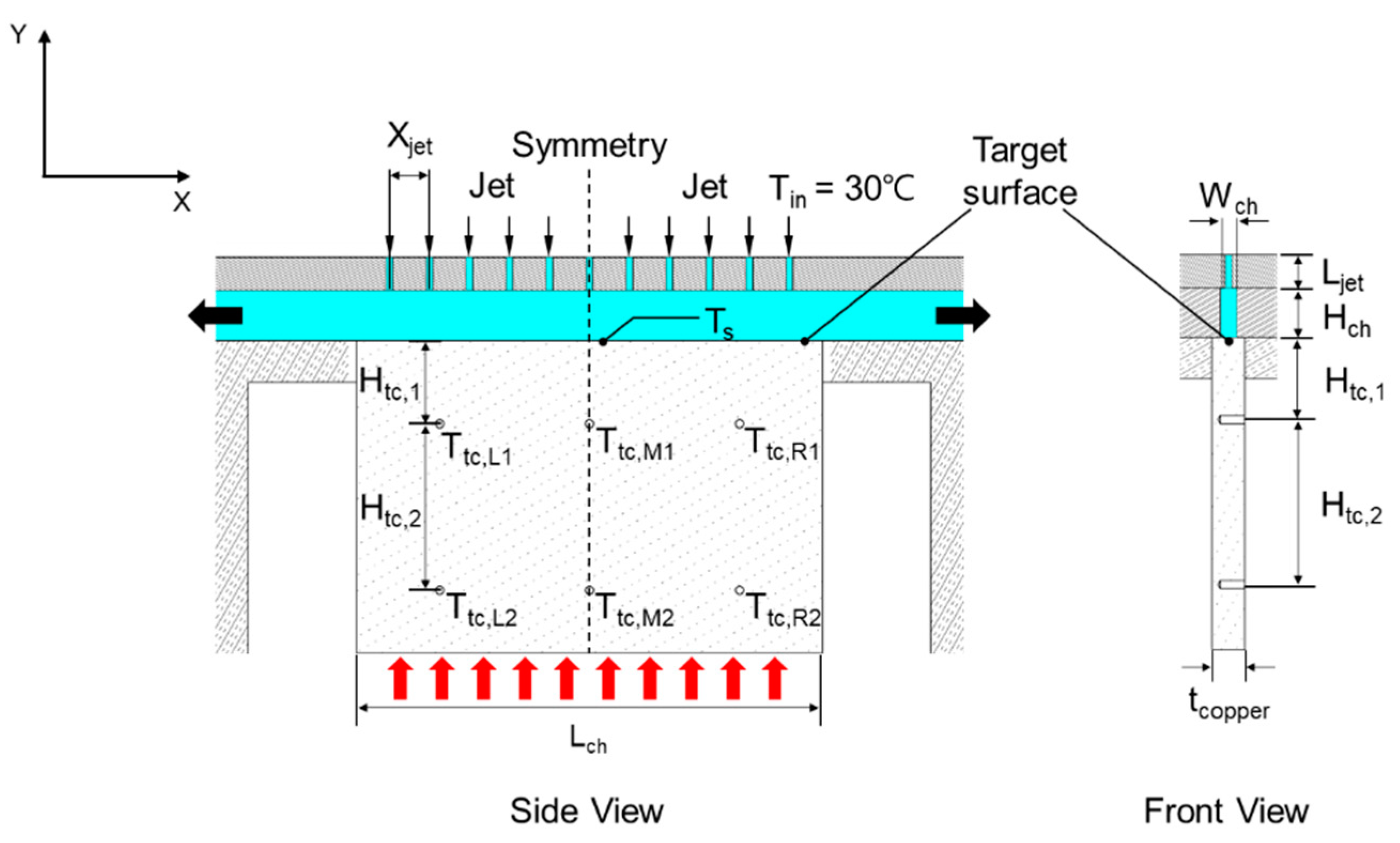
3.1. Model Description
3.2. Numerical Method
3.3. Validation of Numerical Model
4. Results and Discussion
4.1. Experimental Results
4.2. Numerical Results
4.2.1. Jet Exit Velocity Variation
4.2.2. Flow Field and Heat Transfer Coefficient
5. Conclusions
- (1)
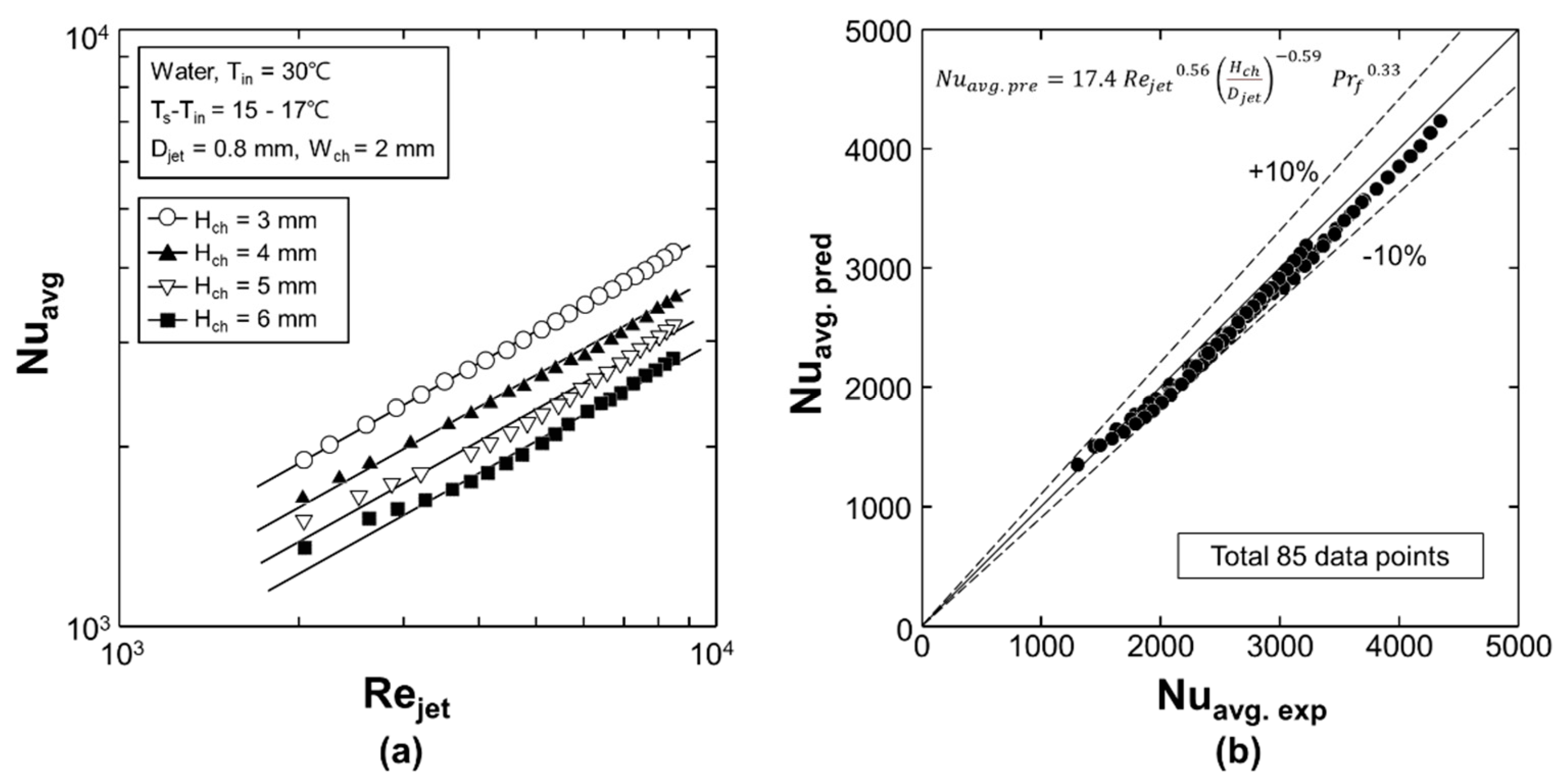
- Experimental results showed that the average Nusselt number (Nuavg) at the target surface increases with the jet Reynolds number (Rejet) and decreases with the channel height (Hch);
- (2)
- Experimentally measured Nuavg was correlated as a function of Rejet, dimensionless channel height (Hch/Djet), and fluid properties. The correlated Nuavg agreed well within a mean absolute error of 4.31%;
- (3)
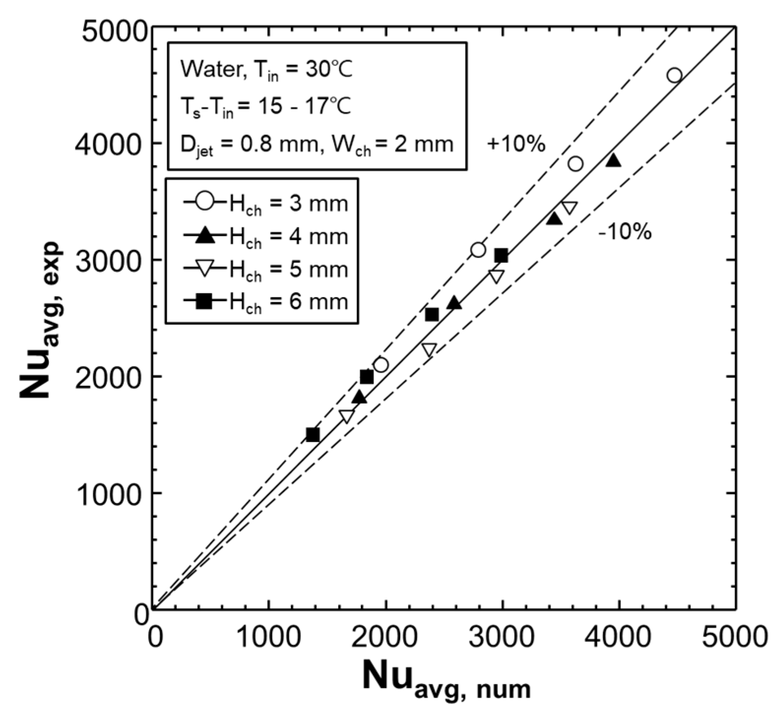
- The numerical simulation using the SST k-ω turbulence model can effectively predict experimentally measured overall heat transfer rate of the channel impingement configuration within a 10% error;
- (4)
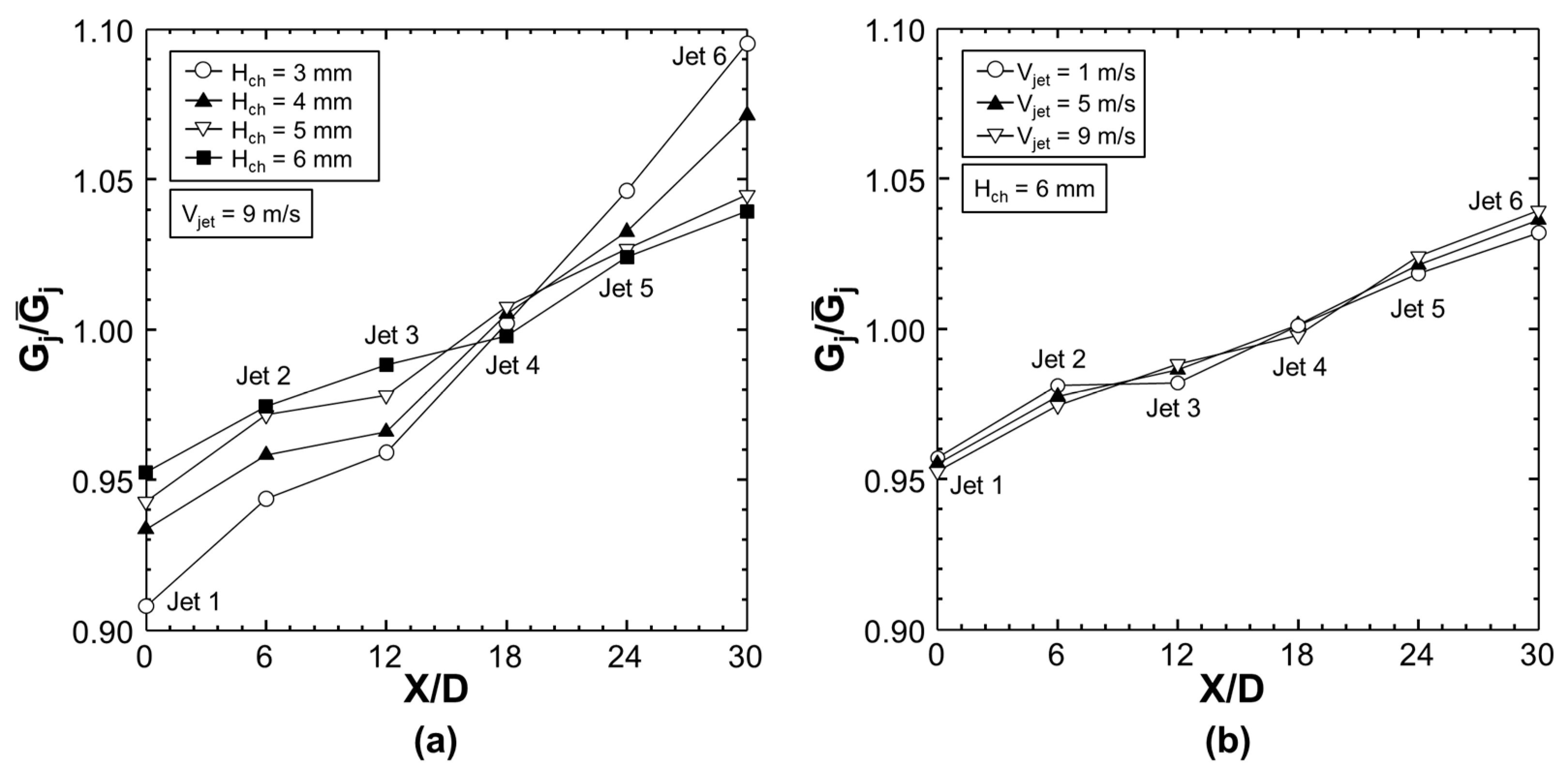
- Numerical results showed that a jet exit velocity variation occurs along the channel. The jet exit velocity variation was significantly affected by Hch and moderately affected by the average jet velocity (Vjet);
- (5)
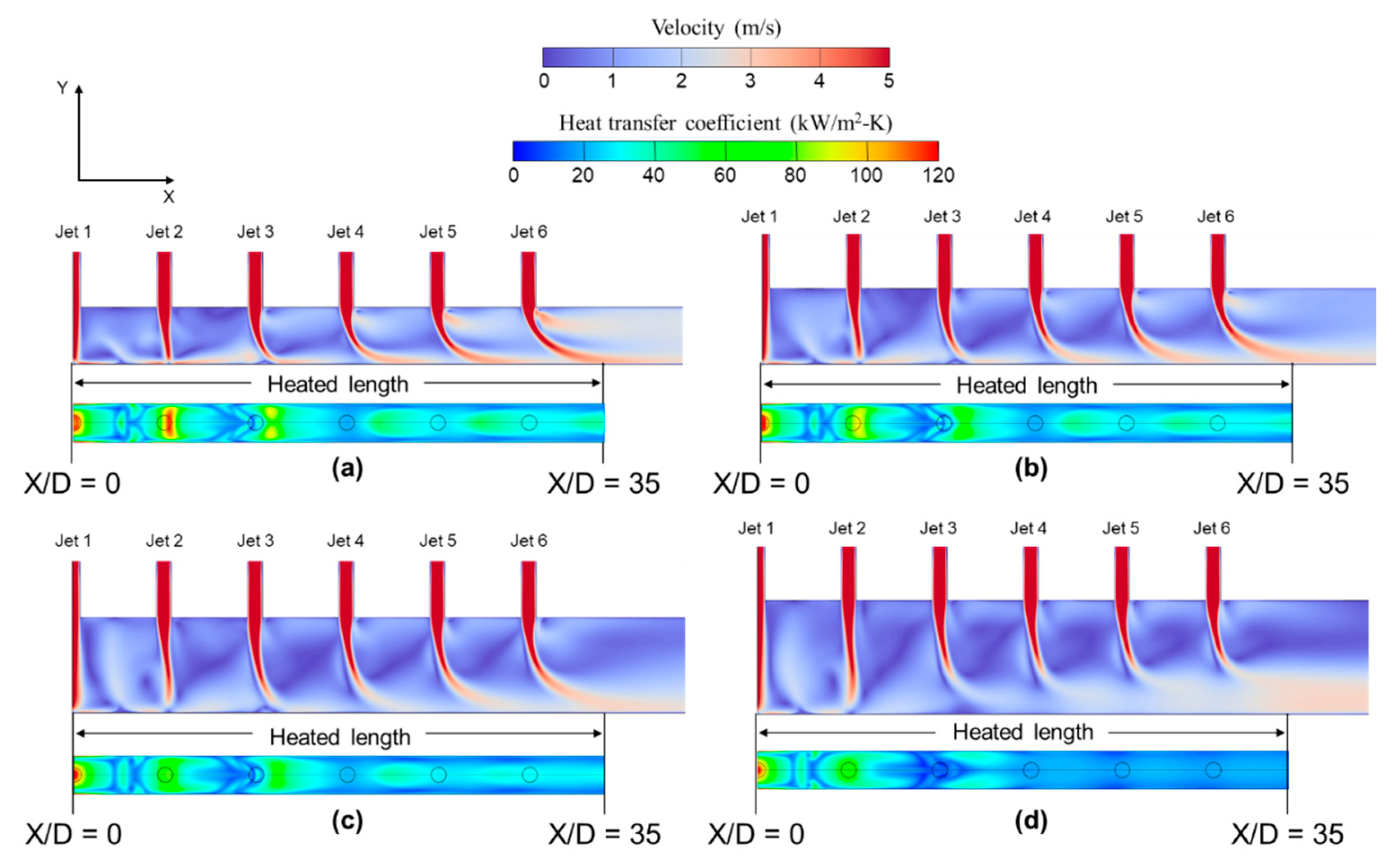
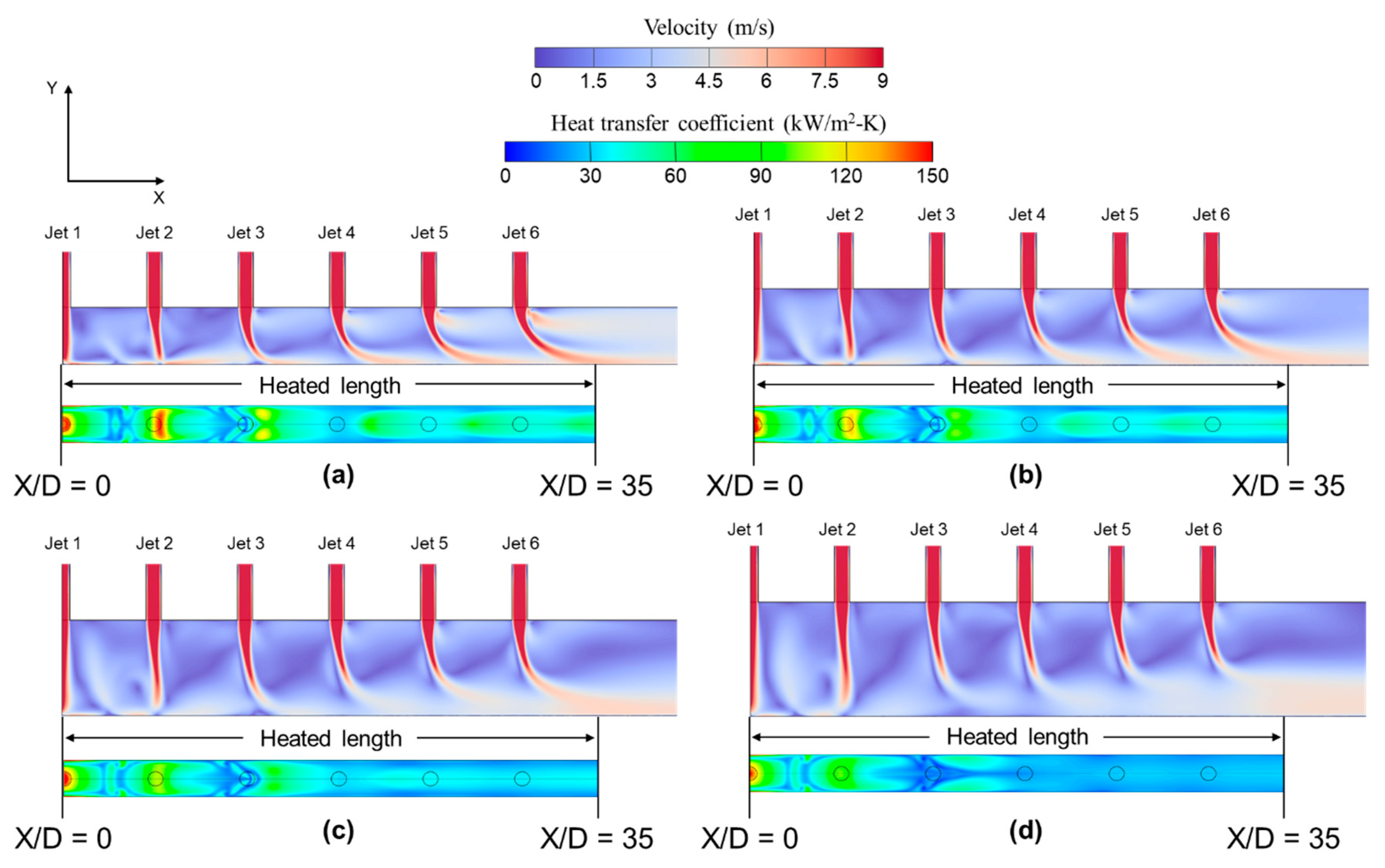
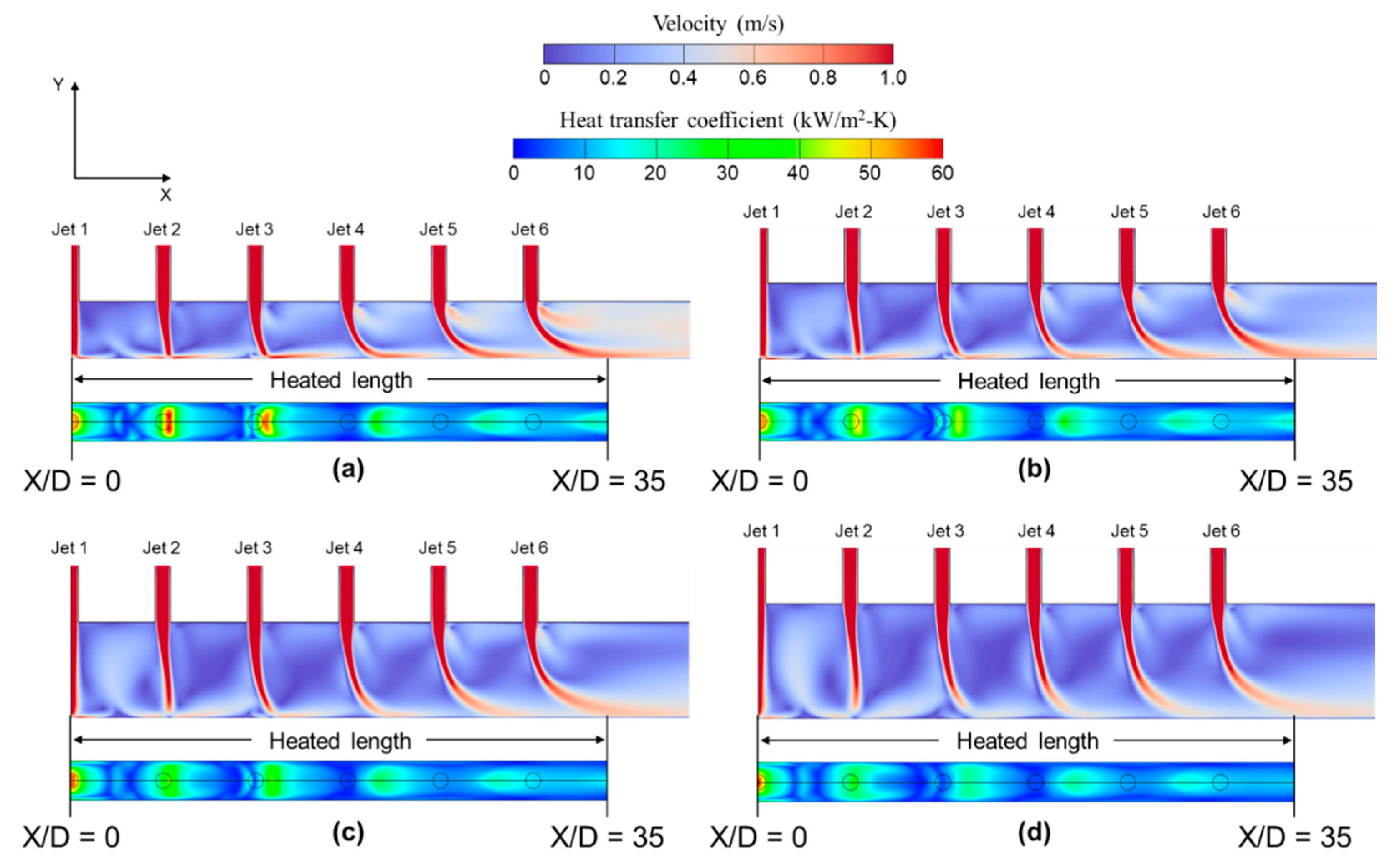
- The crossflow inside the channel deflects the jet potential core in the streamwise direction, and the stagnation regions occurred at the downstream location. The jet deflection reduced the stagnation region heat transfer, evident at the downstream located jets. The stagnation region heat transfer coefficient decreased with increasing channel height because the jet loses momentum traveling a long distance to the target surface;
- (6)
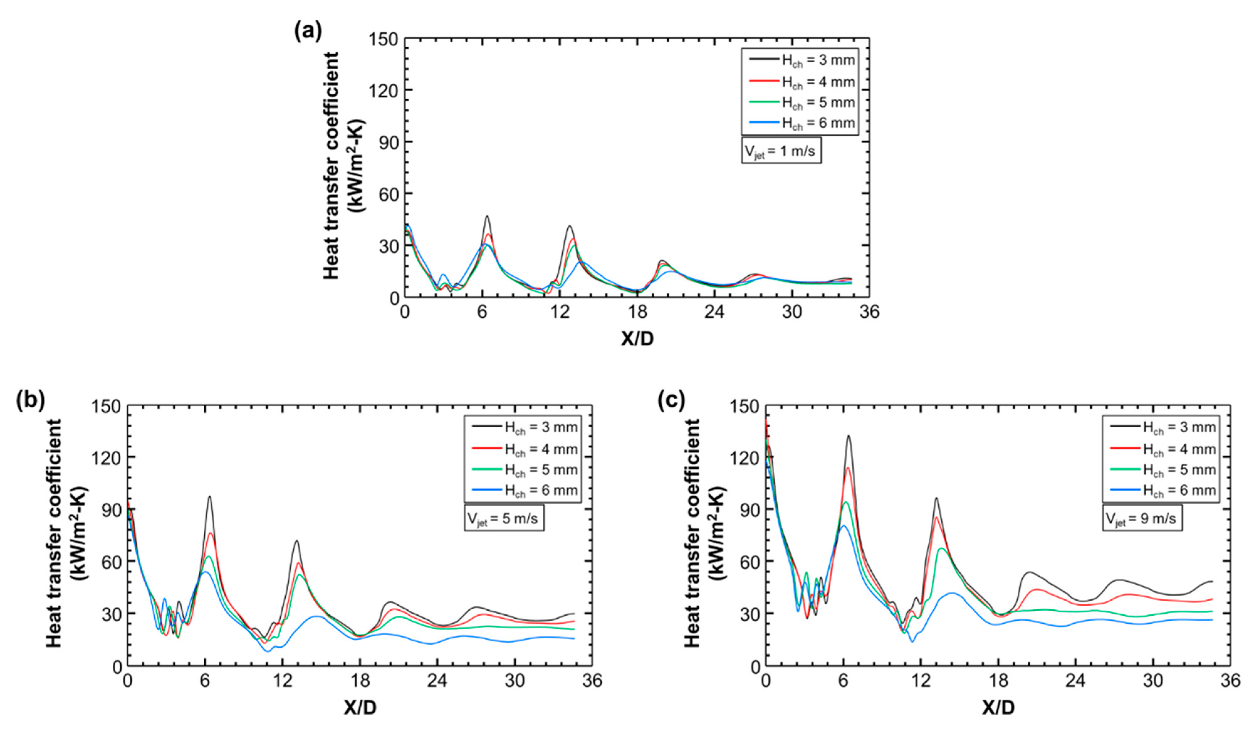
- At high Vjet, a stronger wall jet covers the rear section of the stagnation region and the heat transfer at the intervals between stagnation regions increase. However, at high Hch, the jet was unable to penetrate the wall attached crossflow at the downstream location, and peaks in the heat transfer coefficient at the stagnation region faded away;
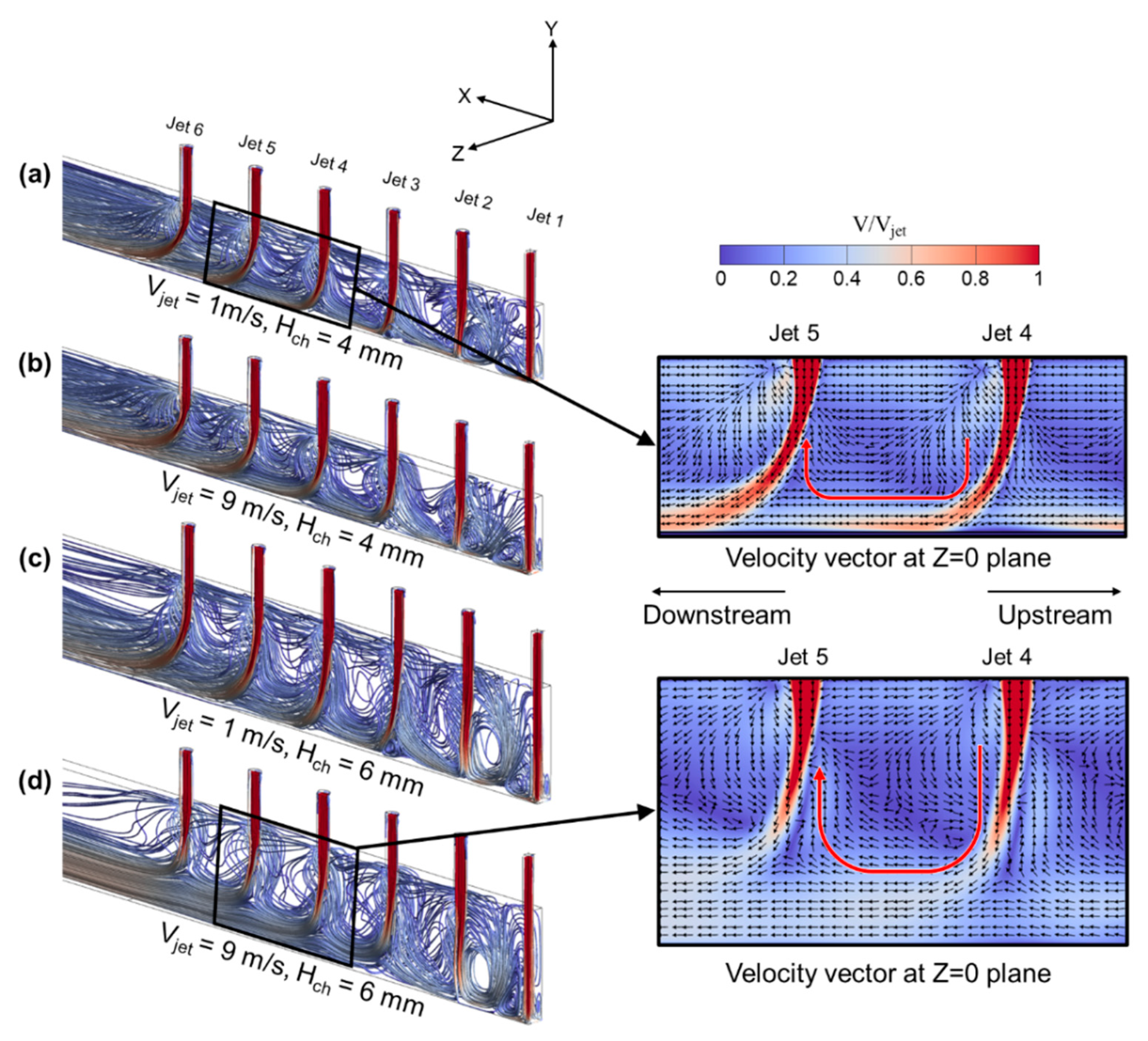
- (7)
- U-shaped rotating flow structures formed by the wall attached crossflow and upstream jet were observed regardless of Hch and Vjet. Shear interaction between the U-shaped flow structures and the downstream jet caused a detrimental effect on the velocity evolution and induced jet momentum loss.
Author Contributions
Funding
Conflicts of Interest
References
- Harms, T.M.; Kazmierczak, M.J.; Gerner, F.M. Developing convective heat transfer in deep rectangular micro-channels. Int. J. Heat Fluid Flow 1999, 20, 149–157. [Google Scholar] [CrossRef]
- Qu, W.; Mudawar, I. Experimental and numerical study of pressure drop and heat transfer in a single-phase micro-channel heat sink. Int. J. Heat Mass Transf. 2002, 45, 2549–2565. [Google Scholar] [CrossRef]
- Memon, S.A.; Cheema, T.A.; Kim, G.M.; Park, C.W. Hydrothermal investigation of a microchannel heat sink using secondary flows in trapezoidal and parallel orientations. Energies 2020, 13, 5616. [Google Scholar] [CrossRef]
- Zhang, Y.-D.; Chen, M.-R.; Wu, J.-H.; Hung, K.-S.; Wang, C.-C. Performance improvement of a double-layer microchannel heat sink via novel fin geometry—A numerical study. Energies 2021, 14, 3585. [Google Scholar] [CrossRef]
- Rybicki, J.R.; Mudawar, I. Single-phase and two-phase cooling characteristics of upward-facing and downward-facing sprays. Int. J. Heat Mass Transf. 2006, 49, 5–16. [Google Scholar] [CrossRef]
- Estes, K.A.; Mudawar, I. Correlation of Sauter mean diameter and critical heat flux for spray cooling of small surfaces. Int. J. Heat Mass Transf. 1995, 38, 2985–2996. [Google Scholar] [CrossRef]
- Natarajan, G.; Bezama, R.J. Microjet cooler with distributed returns. Heat Transf. Eng. 2007, 28, 779–787. [Google Scholar] [CrossRef]
- Rattner, A.S. General characterization of jet impingement array heat sinks with interspersed fluid extraction ports for uniform high-flux cooling. J. Heat Transf. 2017, 139, 082201. [Google Scholar] [CrossRef]
- Paniagua-Guerra, L.E.; Sehgal, S.; Gonzalez-Valle, C.U.; Ramos-Alvarado, B. Fractal channel manifolds for microjet liquid cooled heat sinks. Int. J. Heat Mass Transf. 2019, 138, 257–266. [Google Scholar] [CrossRef]
- Wu, R.; Fan, Y.; Hong, T.; Zou, H.; Hu, R.; Luo, X. An immersed jet array impingement cooling device with distributed returns for direct body liquid cooling of high power electronics. Appl. Ther. Eng. 2019, 162, 114259. [Google Scholar] [CrossRef]
- Xing, Y.; Spring, S.; Weigand, B. Experimental and numerical investigation of heat transfer characteristics of inline and staggered arrays of impinging jets. J. Heat Transf. Trans. ASME 2010, 132. [Google Scholar] [CrossRef]
- Hollworth, B.R.; Lehmann, G.; Rosiczkowski, J. Arrays of impinging jets with spent fluid removal through vent holes on the target surface, Part 2: Local heat transfer. J. Eng. Power Trans. ASME 1983, 105, 393–402. [Google Scholar] [CrossRef]
- Huber, A.M.; Viskanta, R. Effect of jet-jet spacing on convective heat transfer to confined, impinging arrays of axisymmetric air jets. Int. J. Heat Mass Transf. 1994, 37, 2859–2869. [Google Scholar] [CrossRef]
- Cho, H.H.; Rhee, D.H. Local heat/mass transfer measurement on the effusion plate in impingement/effusion cooling system. J. Turbomach. Trans. ASME 2001, 123, 601–608. [Google Scholar] [CrossRef]
- Hoberg, T.B.; Onstad, A.J.; Eaton, J.K. Heat transfer measurement for jet impingement arrays with local extraction. Int. J. Heat Fluid Flow 2010, 31, 460–467. [Google Scholar] [CrossRef]
- Ricklick, M.; Kapat, J.S.; Heidmann, J. Sidewall effects on heat transfer coefficient in a narrow impingement channel. J. Theromphys. Heat Transf. 2010, 24, 123–132. [Google Scholar] [CrossRef]
- Fechter, S.; Terzis, A.; Ott, P.; Weigand, B.; von Wolfersdorf, J.; Cochet, M. Experimental and numerical investigation of narrow impingement cooling channels. Int. J. Heat Mass Transfer. 2013, 67, 1208–1219. [Google Scholar] [CrossRef]
- Terzis, A.; Ott, P.; von Wolfersdorf, J.; Weigand, B.; Cochet, M. Detailed heat transfer distribution of narrow impingement channels for cast-in turbine airfoils. ASME J. Turbomach. 2014, 136, 091011. [Google Scholar] [CrossRef]
- Hossain, J.; Tran, L.V.; Kapat, J.S.; Fernandez, E.; Kumar, R. An experimental study of detailed flow and heat transfer analysis in a single row narrow impingement channel. In Proceedings of the Turbo Expo 2014: Turbine Technical Conference and Exposition, Düsseldorf, Germany, 16–20 June 2014. [Google Scholar]
- Zhang, J.; Sun, Y.; Li, J.; He, X. Study on the hybrid cooling of the flame tube in a small triple-swirler combustor. Energies 2020, 13, 5554. [Google Scholar] [CrossRef]
- Agrawal, C.; Kumar, R.; Gupta, A.; Chatterjee, B. Rewetting and maximum surface heat flux during quenching of hot surface by round water jet impingement. Int. J. Heat Mass Transf. 2012, 55, 4772–4782. [Google Scholar] [CrossRef]
- Johns, M.E.; Mudawar, I. An ultra-high power two-phase jet impingement avionic clamshell module. ASME.J. Electron. Packag. 1996, 118, 264–270. [Google Scholar] [CrossRef]
- Narumanchi, S.V.J.; Hassani, V.; Bharathan, D. Modeling Single-Phase and Boiling Liquid Jet Impingement Cooling in Power Electronics; National Renewable Energy Laboratory (NREL): Golden, CO, USA, 2005.
- Obot, N.T.; Trabold, T.A. Impingement heat transfer within arrays of circular jets: Part 1-Effects of minimum, intermediate, and complete crossflow for small and large spacings. J. Heat Transf. Trans. ASME 1987, 109, 872–879. [Google Scholar] [CrossRef]
- Huang, Y.; Ekkad, S.V.; Han, J.C. Detailed heat transfer distributions under an array of orthogonal impinging jets. J. Thermophys. Heat Transf. 1998, 12, 73–79. [Google Scholar] [CrossRef]
- Miao, J.M.; Wu, C.Y.; Chen, P.H. Numerical investigation of confined multiple-jet impingement cooling over a flat plate at different crossflow orientaions. Numer. Heat Transf. Part A Appl. 2009, 55, 1019–1050. [Google Scholar] [CrossRef]
- Sung, M.K.; Mudawar, I. Single-phase hybrid micro-channel/micro-jet impingement cooling. Int. J. Heat Mass Transf. 2008, 51, 4342–4352. [Google Scholar] [CrossRef]
- Sung, M.K.; Mudawar, I. Effects of jet pattern on single-phase cooling performance of hybrid micro-channel/micro-circular-jet-impingement thermal management scheme. Int. J. Heat Mass Transf. 2008, 51, 4614–4627. [Google Scholar] [CrossRef]
- Barrau, J.; Chemisana, D.; Rosell, J.; Tadrist, L.; Ibanez, M. An experimental study of a new hybrid jet impingement/micro-channel cooling scheme. Appl. Ther. Eng. 2010, 30, 2058–2066. [Google Scholar] [CrossRef] [Green Version]
- Barrau, J.; Omri, M.; Chemisana, D.; Rosell, J.; Ibanez, M.; Tadrist, L. Numerical study of a hybrid jet impingement/micro-channel cooling scheme. Appl. Ther. Eng. 2012, 33–34, 237–245. [Google Scholar] [CrossRef]
- Ansys Fluent 20.1. Theory Guide 2019; ANSYS, Inc.: Canonsburg, PA, USA, 2019. [Google Scholar]
- Menter, F.R. Zonal two equation k-ω turbulence models for aerodynamic flows. In Proceedings of the 24th Fluid Dynamics Conference, Orlando, FL, USA, 6–9 July 1993. [Google Scholar]
- Menter, F.R. Two-equation eddy-viscosity turbulence models for engineering applications. AIAA J. 1994, 32, 1598–1605. [Google Scholar] [CrossRef] [Green Version]
- Alimohammadi, S.; Murray, D.B.; Persoons, T. Experimental validation of a computational fluid dynamics methodology for transitional flow heat transfer characteristics of a steady impinging jet. J. Heat Transf. 2014, 136, 091703. [Google Scholar] [CrossRef] [Green Version]
- Zuckerman, N.; Lior, N. Jet impingement heat transfer: Physics, correlations, and numerical modeling. Adv. Heat Transf. 2006, 39, 565–631. [Google Scholar]
- Van Doormaal, J.P.; Raithby, G.D. Enhancements of the simple method for predicting incompressible fluid flows. Numer. Heat Transf. 1984, 11, 147–163. [Google Scholar]


| Djet (mm) | Xjet (mm) | Ljet (mm) | Njet | Wch (mm) | Hch (mm) | Lch (mm) | tcopper (mm) | Htc,1 (mm) | Htc,2 (mm) |
|---|---|---|---|---|---|---|---|---|---|
| 0.8 | 4.8 | 3 | 11 | 2 | 3, 4, 5, 6 | 56 | 4 | 8 | 22 |
| Hch (mm) | Vjet (m/s) | Rejet | q″ (W/cm2) | Number of Cases |
|---|---|---|---|---|
| 3 | 2.00–8.27 | 2044–8475 | 13.2–35.4 | 22 |
| 4 | 1.98–8.35 | 2031–8552 | 14.7–30.5 | 21 |
| 5 | 2.00–8.31 | 2044–8509 | 13.9–29.7 | 21 |
| 6 | 2.00–8.28 | 2047–8478 | 12.2–26.4 | 21 |
| Number of Elements (×106) | Average Heat Transfer Coefficient (kW/m2-K) |
|---|---|
| 4.62 | 46.96 |
| 6.78 | 45.18 |
| 7.94 | 46.27 |
| 10.25 | 46.58 |
| 12.34 | 46.45 |
| Hch (mm) | Vjet (m/s) | q″ (W/cm2) |
|---|---|---|
| 3, 4, 5, 6 | 1 | 10 |
| 3, 4, 5, 6 | 5 | 18 |
| 3, 4, 5, 6 | 9 | 30 |
Publisher’s Note: MDPI stays neutral with regard to jurisdictional claims in published maps and institutional affiliations. |
© 2021 by the authors. Licensee MDPI, Basel, Switzerland. This article is an open access article distributed under the terms and conditions of the Creative Commons Attribution (CC BY) license (https://creativecommons.org/licenses/by/4.0/).
Share and Cite
Shin, M.-S.; Senguttuvan, S.; Kim, S.-M. Investigations of Flow and Heat Transfer Characteristics in a Channel Impingement Cooling Configuration with a Single Row of Water Jets. Energies 2021, 14, 4327. https://doi.org/10.3390/en14144327
Shin M-S, Senguttuvan S, Kim S-M. Investigations of Flow and Heat Transfer Characteristics in a Channel Impingement Cooling Configuration with a Single Row of Water Jets. Energies. 2021; 14(14):4327. https://doi.org/10.3390/en14144327
Chicago/Turabian StyleShin, Min-Seob, Santhosh Senguttuvan, and Sung-Min Kim. 2021. "Investigations of Flow and Heat Transfer Characteristics in a Channel Impingement Cooling Configuration with a Single Row of Water Jets" Energies 14, no. 14: 4327. https://doi.org/10.3390/en14144327
APA StyleShin, M.-S., Senguttuvan, S., & Kim, S.-M. (2021). Investigations of Flow and Heat Transfer Characteristics in a Channel Impingement Cooling Configuration with a Single Row of Water Jets. Energies, 14(14), 4327. https://doi.org/10.3390/en14144327