1. Introduction
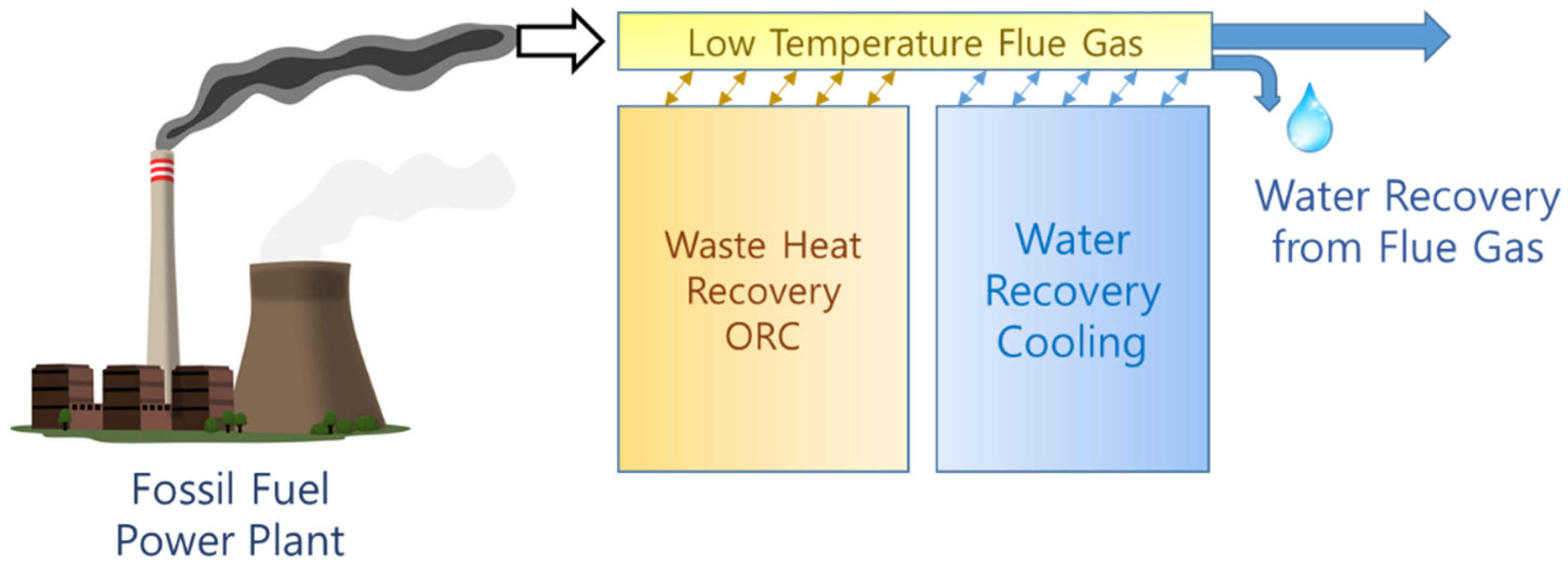
Power plants that use fossil fuels—such as coal-fired power plants—exhibit problems in fuel consumption, eventually resulting in high CO
2 emissions, substantial water consumption, and harmful gas emissions. In a thermal power plant, heat and water recovery from flue gas can reduce CO
2 emissions and water requirements. Over the years, the organic Rankine cycle (ORC) has been used for waste heat recovery (WHR) from various heat sources, including automobile exhaust gas [
1] and power plant flue gas.
The sensitivity of the power generation industry to water availability limits is widespread, and increasing; this has increased the burden on power plant operators to save water [
2]. In the Netherlands, a typical 400-MW coal-fired power plant equipped with a wet flue gas desulfurization unit utilizes 30 ton/h of makeup water in the boiler feedwater. Meanwhile, 150 ton/h of water in the flue gas is released through the stack; moreover, 90–120 ton/h of water is released by plants without flue gas desulfurization units [
3]. Therefore, water recovery from flue gas, and its reuse, can reduce water consumption in thermal power plants [
4]. Furthermore, the low temperature of the latent heat recovered can be utilized by heat pumps for district heating [
5].
Condensing the moisture in the flue gas after it has passed through the pollution control system can reduce emissions even further. In the late 1980s, Haldor Topsoe A/S created and patented wet sulfuric acid, in which SO
x and water vapor react to form liquid sulfuric acid (H
2SO
4) at high concentrations by cooling the exhaust gas to lower than the dew point of sulfuric acid [
6]. Zukeran et al. [
7] studied the removal rate of SO
2 and particulate matter (PM) reduction in marine engines via water condensation in flue gas. Mist particles were formed as a result of water condensation, and they were collected using an electrostatic precipitator. Jeong et al. [
8] used an integrated condensing heat exchanger system composed of a heat exchanger, a cooling water storage tank, and an acid removal system.
The PM produced by fossil fuel combustion is composed of filterable particulate matter (FPM) and condensable particulate matter (CPM). CPM is a gaseous material at flue gas temperature prior to discharge; however, it forms a particulate substance (PM
2.5) after cooling in the plume. Because FPM emissions have significantly reduced due to the rapid development of FPM technology, CPM discharge has recently emerged as an important issue [
9]. Qi et al. [
10] showed that a low-low temperature electrostatic precipitator could reduce the amount of CPM considerably by cooling the exhaust gas below the dew point.
Furthermore, Shuangchen et al. [
11] studied the environmental impact of high-humidity flue gas discharged by power plants, and proposed that flue gas emissions of high humidity promoted the secondary transformation of air pollutants and reduced atmospheric visibility.
In the case of the ORC for waste heat recovery, the system must be optimized to produce the maximum power output from the given heat source. Many researchers have conducted experiments on small-scale ORC systems for various purposes. Malavolta et al. [
12] built and tested a small-scale ORC system with a scroll expander for a domestic combined heat and power plant (electric power output of 1–3 kW). Lecompte et al. [
13] presented the experimental results for an 11-kWe ORC prototype with a twin-screw expander, which was utilized to calibrate and validate off-design models. Shao et al. [
14] experimentally studied the performance and features of a kW-scale ORC system under various cooling conditions. For low-grade heat recovery, Bianchi et al. [
15] varied the heat source temperature and organic fluid feed pump velocity in a micro-ORC driven by a piston expander. Yang et al. [
16] experimentally investigated a 3-kW ORC with a scroll expander for low-grade waste heat under different operating parameters. Rosset et al. [
17] experimentally examined the performance of a novel turbogenerator (TG) supported by gas-lubricated bearings for small-scale ORC systems, generating an electrical power of up to 2.3 kW.
In this study, a lab-scale system for heat and water recovery from flue gas was developed and tested. The system comprises an ORC for power generation with the integration of a pumped heat pipe cooling (HPC) cycle that uses a single working fluid to execute heat extraction for power output and water recovery.
3. Experimental Setup
In this study, a lab-scale system for heat and water recovery from flue gas was developed and tested.
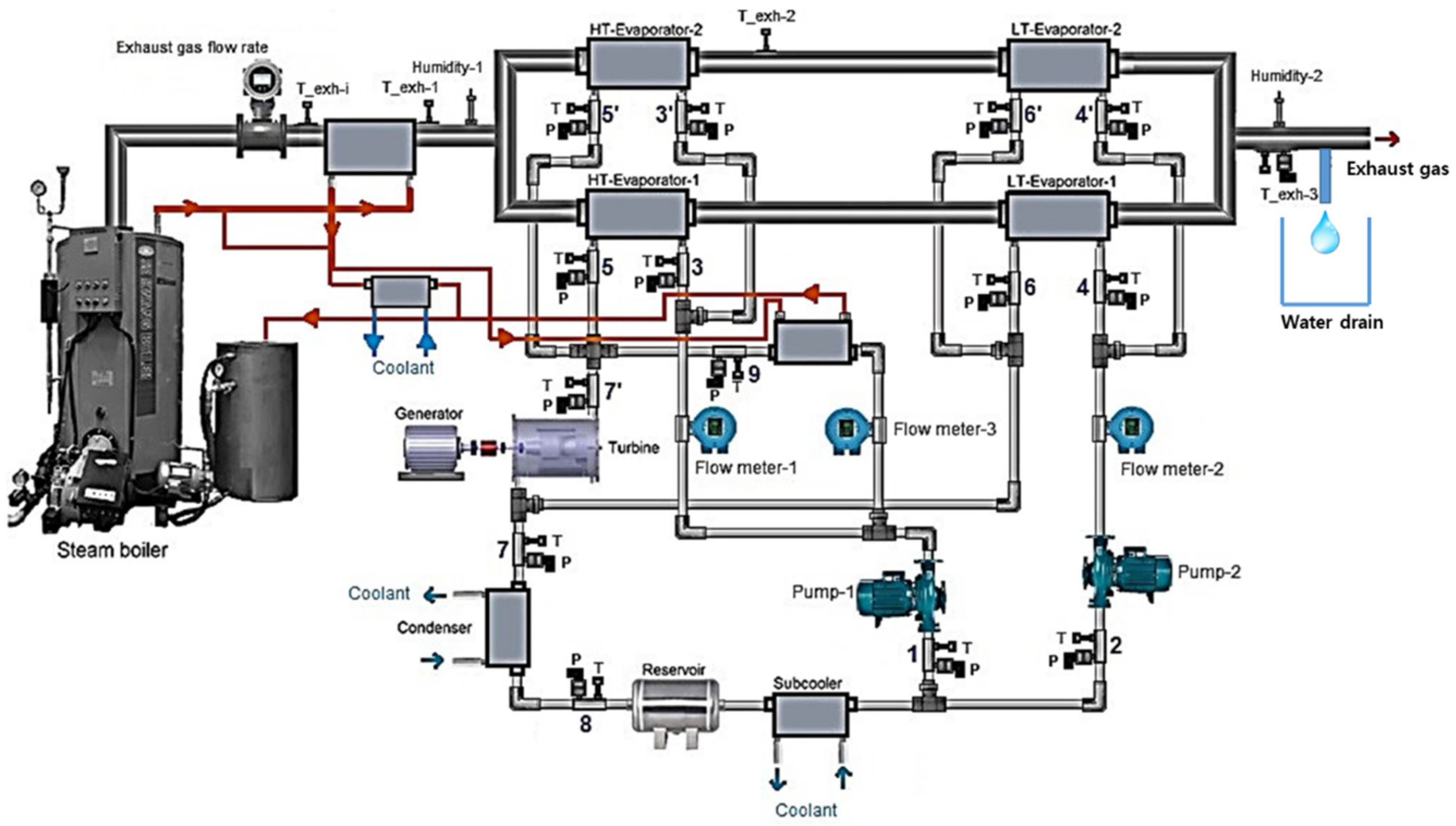
Figure 2 shows a schematic of the WHWR system. In the experiment, flue gas from a steam boiler using natural gas as fuel was used. R134a was used as the working fluid, and coolant water was used to condense the working fluid. After passing through the condenser and reservoir, the working fluid was split, with one stream supplied to a high-temperature (HT) evaporator by a high-pressure pump for the ORC part, and the other stream supplied to the LT evaporator by a low-pressure pump for the pumped HPC unit. The flue gas from the steam boiler above 200 °C was first cooled by the steam from the steam boiler to below 150 °C in order to simulate the lower temperature of flue gas from the fossil fuel power plant. Two parallel heat exchangers were used for each HT and LT evaporator, in order to maximize the heat and water recovery performance.
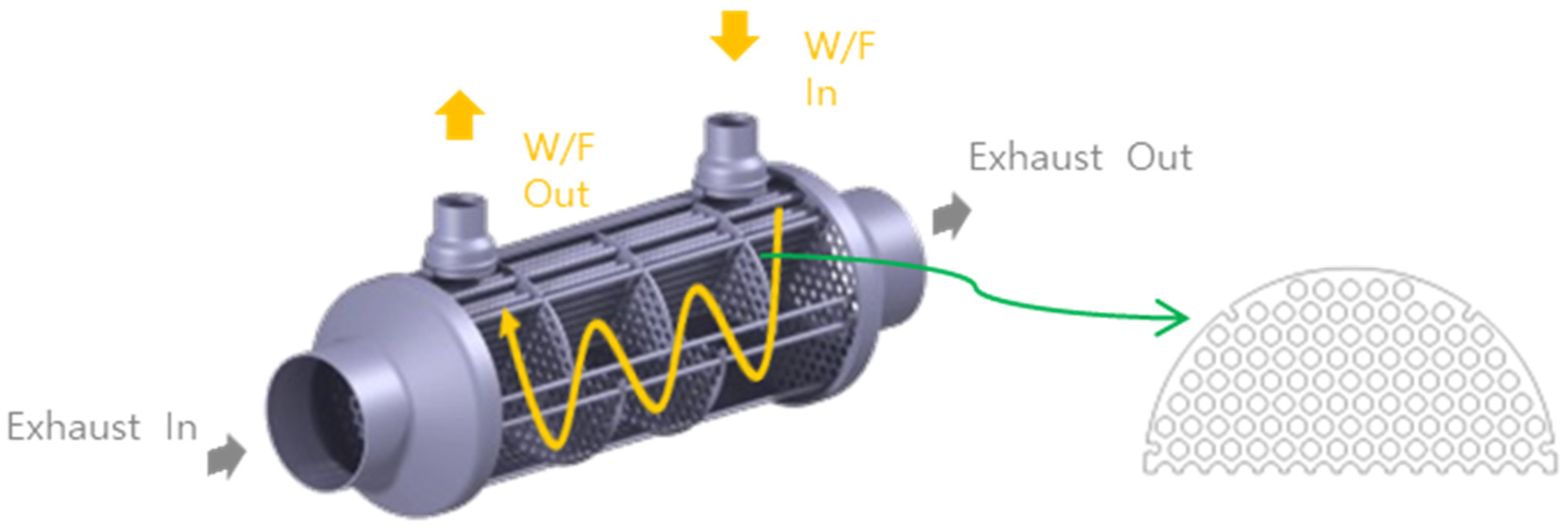
A scroll expander was used for power generation, and a load bank was used to dissipate the power output and adjust the rotation speed of the expander. The torque (model: UNIPULSE UTM II-50 NM, 0–50 Nm ± 0.03% FS) and speed (3600 pulses per rotation) of the expander were measured to determine the mechanical power output. The mass flow rate of the working fluid of the ORC part and the pumped HPC part was measured using three mass flow meters (model: RHEONIK RHM 08, 0.3~50 kg/min ± 0.1% RV). To evaluate the water recovery efficiency, two relative humidity sensors (model: EE310, 0–100% RH ± 1.3% RH) were used to measure the relative humidity before and after the WHWR system. Pressure sensors (model: Sensys PSH, 0–50 bar and 0–10 bar ± 0.15% FS) and temperature sensors (K-type thermocouple, 0–150 °C ± 0.5 °C) were used to measure the state of the fluid. The heat exchangers for the HT and LT evaporators were shell- and tube-type, as shown in
Figure 3. The flue gas was routed through the tubes of the heat exchangers, while R134a flowed through the shell side. Sight glasses were used to inspect the state of the working fluid after it had passed through the evaporators.
In the previous experiment, the thermal efficiency of the ORC part was too low, due to the difficulty in optimizing the operating conditions of the ORC system, owing to a large mismatch between the capacity of the scroll expander and the low capacity of the burner in the laboratory. Therefore, an additional working fluid (R134a), heated by steam from the boiler to the same state as the working fluid from the waste heat recovery of the flue gas, was added to the inlet of the expander. In
Figure 2, the red line depicts the flow of the steam circulation for this purpose. However, the net power from the waste heat recovery of the flue gas in the increased power was calculated by using the portion of the working fluid (flow meter 1 and flow meter 3) flowing into the expander. This method to optimize the operating conditions of the ORC is not practical for full-scale ORC systems in field applications. However, in a lab-scale ORC system, it is temporary, and can be used to solve the mismatch problem between the obtainable components and demonstrate the potential performance of the system.
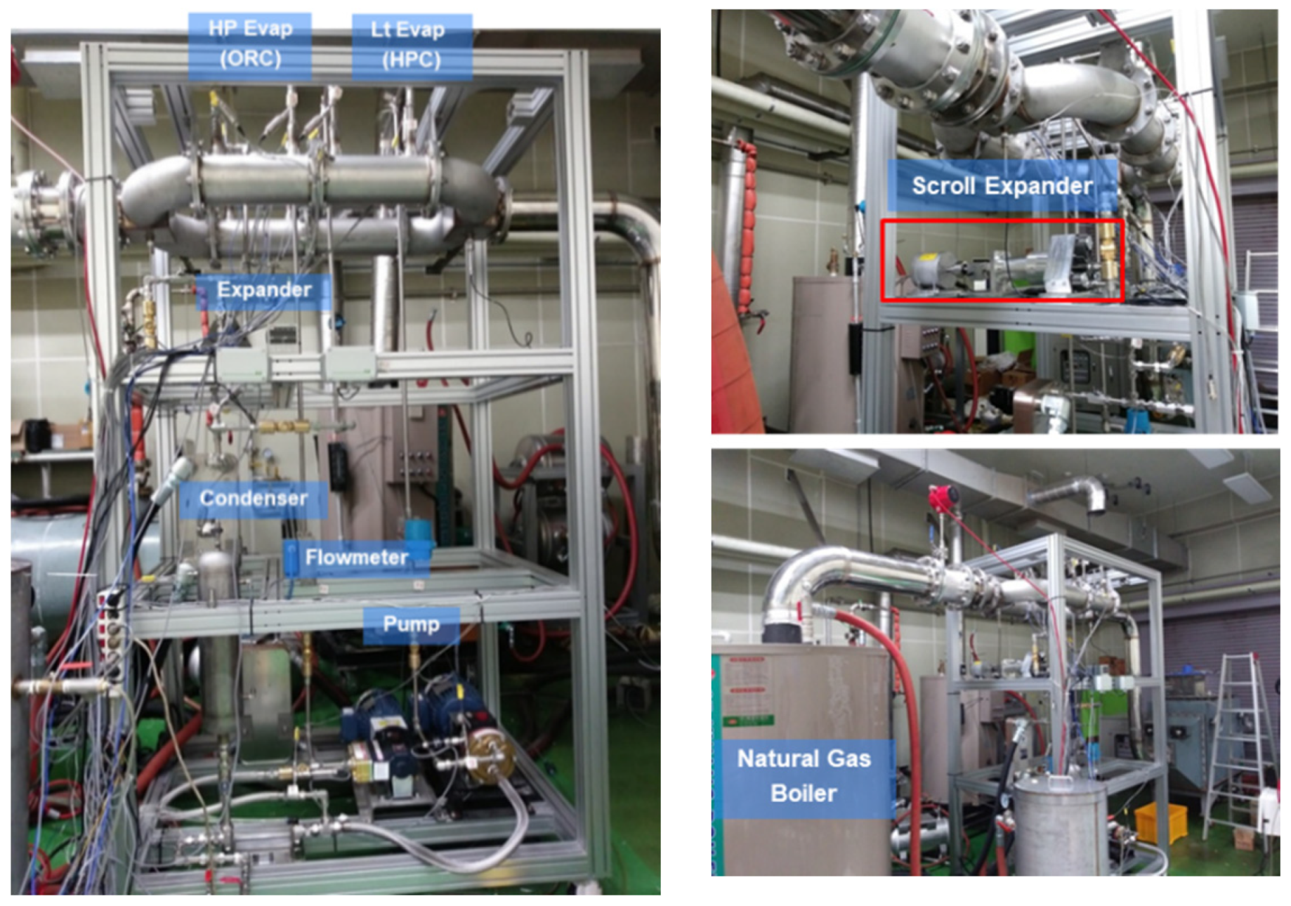
Figure 4 shows the photograph of the experimental setup of the WHWR system.
4. Experimental Procedure
After completely heating the steam boiler, the temperature and mass flow rate of the flue gas flowing into the WHWR system were maintained at constant values. To begin with, the mass flow rate of the working fluid and the speed of the expander of the ORC part were optimized by adjusting the speed of the HP pump and setting the load bank to maximize the power output of the ORC unit from the given waste heat source. Then, to maximize the water recovery efficiency, the mass flow rate of the working fluid in the pumped HPC unit was increased stepwise; however, it was limited to maintaining the state of the working fluid after the LT evaporator was close to the saturated gas state, and avoiding unnecessary circulation.
During the experiment, the temperature, pressure, and flow rate data from the installed sensors were used to calculate the thermodynamic properties of the working fluid, using NIST-REFPROP software [
19], and subsequently used to analyze the experimental data. The mechanical power output (
) was measured by the torque (
T) and rotation speed (
N) of the expander from Equation (1). The isentropic efficiencies of the expander and the pump are expressed in Equations (2) and (3), respectively. The pump work was not measured because the low pump efficiency was not well matched in the lab-scale ORC system, which severely distorts the potential efficiency of the full-scale ORC system in the application; however, it was estimated by the assumed isentropic efficiency of the pump to be 0.7, by considering the general ORC pump efficiency between 0.65 and 0.85 [
20], using Equation (3).
where
h,
s, and
are the specific enthalpy, exit state for the isentropic process, and mass flow rate of the working fluid, respectively.
The net power output of the system was calculated by subtracting the pump work input from the work output of the expander, as expressed in Equation (4).
The thermal efficiency of the ORC was calculated as the ratio of the net power output to the heat recovery of the ORC, as expressed in Equation (5).
The water recovery efficiency was calculated as the ratio of the water vapor pressure difference after passing through the WHWR system and the initial water vapor pressure before passing through the WHWR system, as expressed in Equation (6).
where
Pw,
RH, and
Psat@T are the water vapor pressure, relative humidity, and saturation water vapor pressure at a given temperature, respectively.
5. Results and Discussion
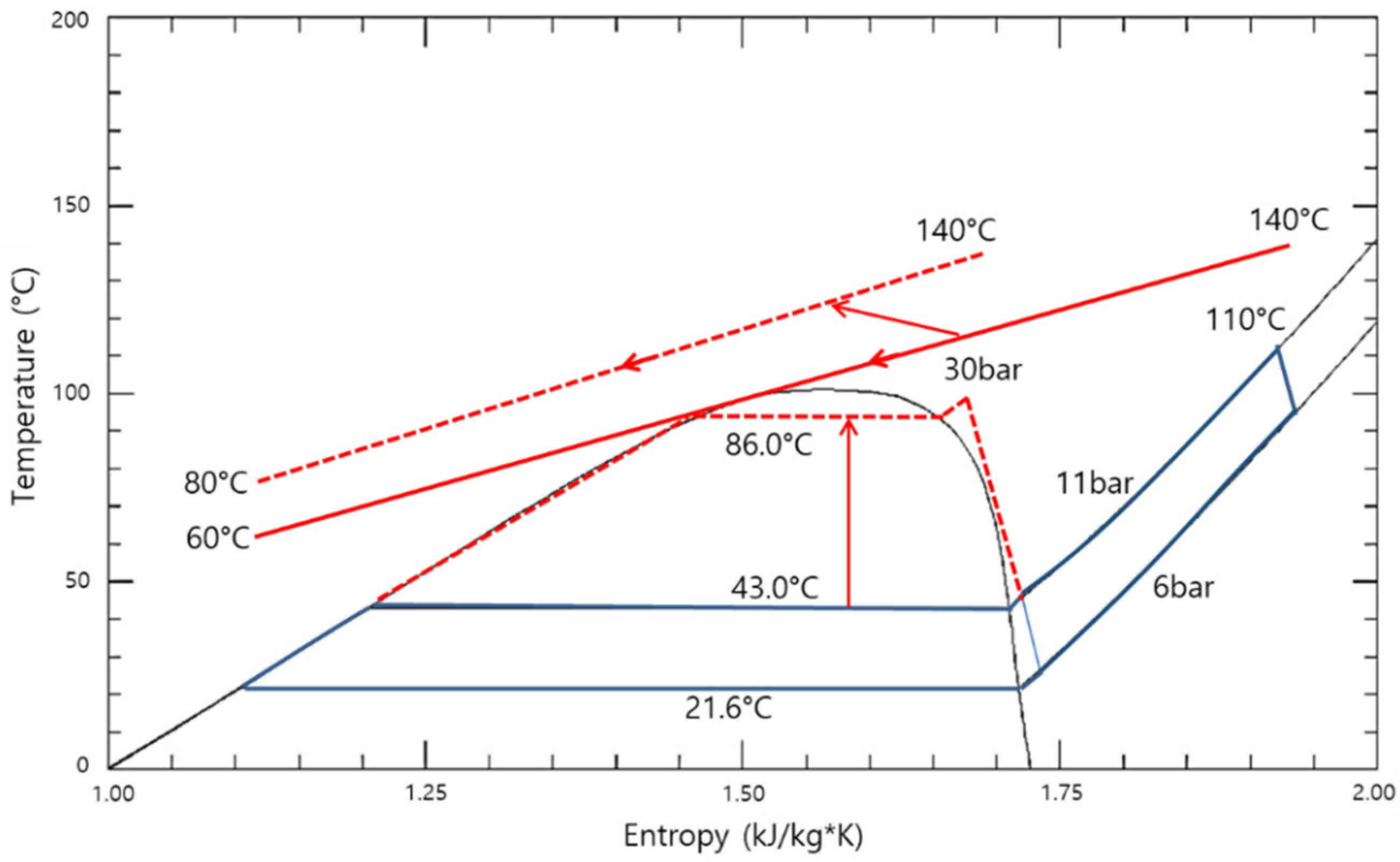
Although the ORC unit was optimized for maximum power from the given flue gas during the experiment, the thermal efficiency of the ORC unit was substantially lower than expected. The operating conditions of the ORC were investigated in order to improve the thermal efficiency of the ORC unit.
Figure 5 (solid lines) depicts the operating conditions of the ORC and flue gas in the temperature and entropy diagrams. The high-pressure side was approximately 11 bar, with an evaporation temperature of 43 °C, while the low-pressure side was 6 bar, with a condensation temperature of 22 °C. Furthermore, the isentropic efficiency of the expander was low, because the operating pressure ratio of 1.8 was too low for the design pressure ratio of 3.5. To improve the thermal efficiency of the ORC unit, the pressure of the high-pressure side must be increased for higher evaporation temperatures, as indicated by the red dashed lines in
Figure 5.
However, optimizing the operating conditions of the ORC unit is challenging, because the capacity of the scroll expander (model: E15H022A-SH) built by Air Squared, Inc. is 1–2 kW, despite the fact that the maximum power from the given flue gas was 200 W. It is difficult to match the capacity of the scroll expander with the capacity of the burner in the laboratory. As a result, to increase the pressure on the high-pressure side, an additional working fluid (R134a) heated by the steam from the boiler to the same state as the working fluid from the waste heat recovery of the flue gas was added to the inlet of the expander. Despite the fact that the power of the expander was increased due to the additional heat input, the net power from the waste heat recovery of the flue gas was calculated using the portion of the working fluid that was allowed to pass into the expander.
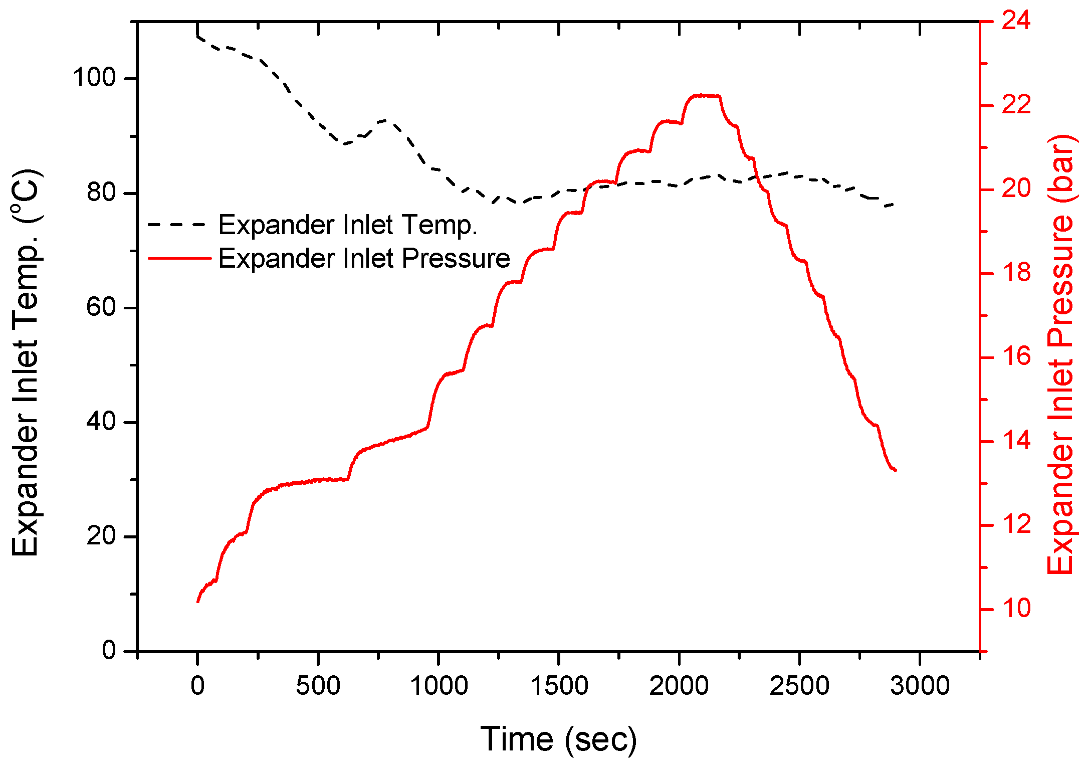
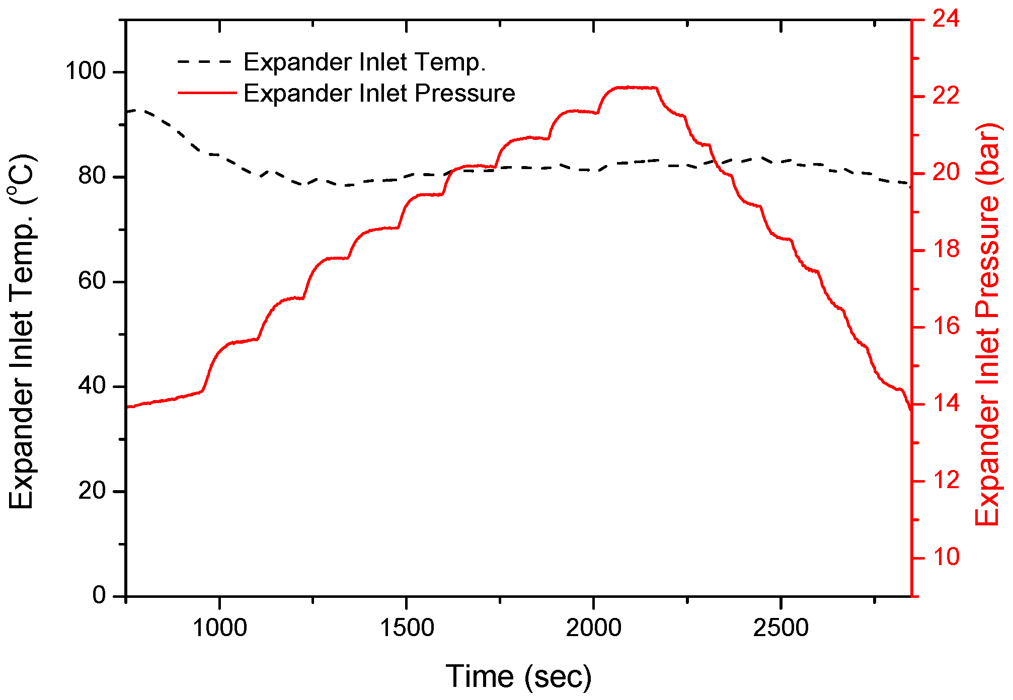
The amount of additional working fluid heated by the steam from the boiler into the expander was increased stepwise; it was then decreased in reverse in order to check the reproducibility of the experiment. As shown in
Figure 6, increasing the amount of additional working fluid into the expander increased the expander inlet pressure from 10 to 22 bar, while the expander inlet temperature slightly decreased from 107 °C to 80 °C, and remained almost constant. The high expander inlet temperature in the early stage was attributed to the thermal inertia of the heat exchangers, because the stored thermal energy of the heat exchanger could be used to heat the working fluid.
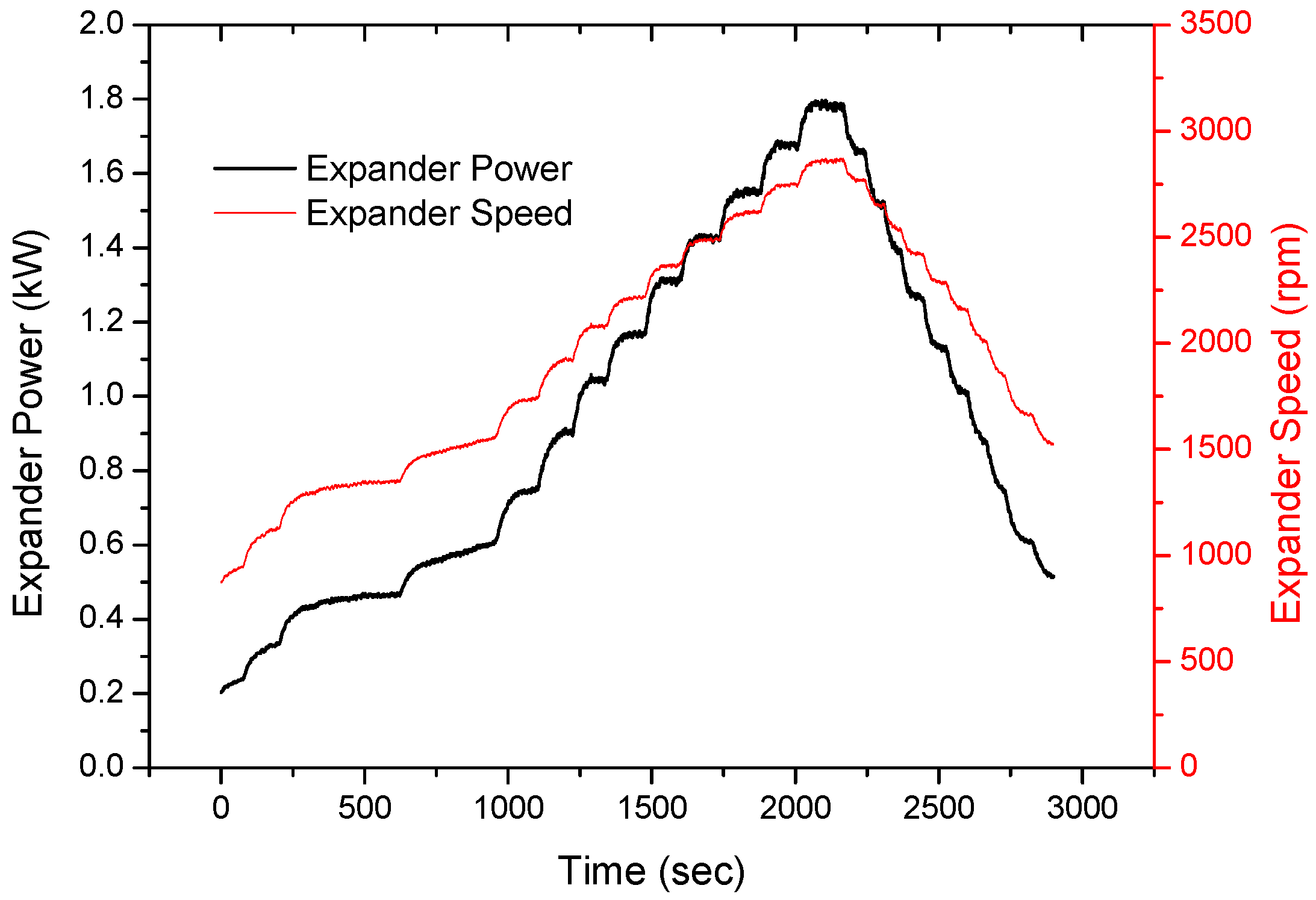
Figure 7 shows that increasing the expander inlet pressure increased the expander speed from 870 to 2840 rpm, and the expander power from 204 to 1790 W (with a maximum uncertainty of 0.67%).
The test results are shown for a relatively short operating time of approximately 3000 s (1 h) under different operating conditions. The performance of the ORC and water recovery system was dependent on the temperature of the cooling water from the cooling tower, which fluctuated during the day. Therefore, to keep the temperature of the cooling water as cold as possible in order to ensure the system’s high performance, the overall operating time to achieve the optimal conditions of the system was kept short during the start of the day. All variables at each operating point were measured stepwise until they stabilized. The amount of additional working fluid heated by the steam into the expander was decreased in reverse in a stepwise manner, in order to check the repeatability of each condition.
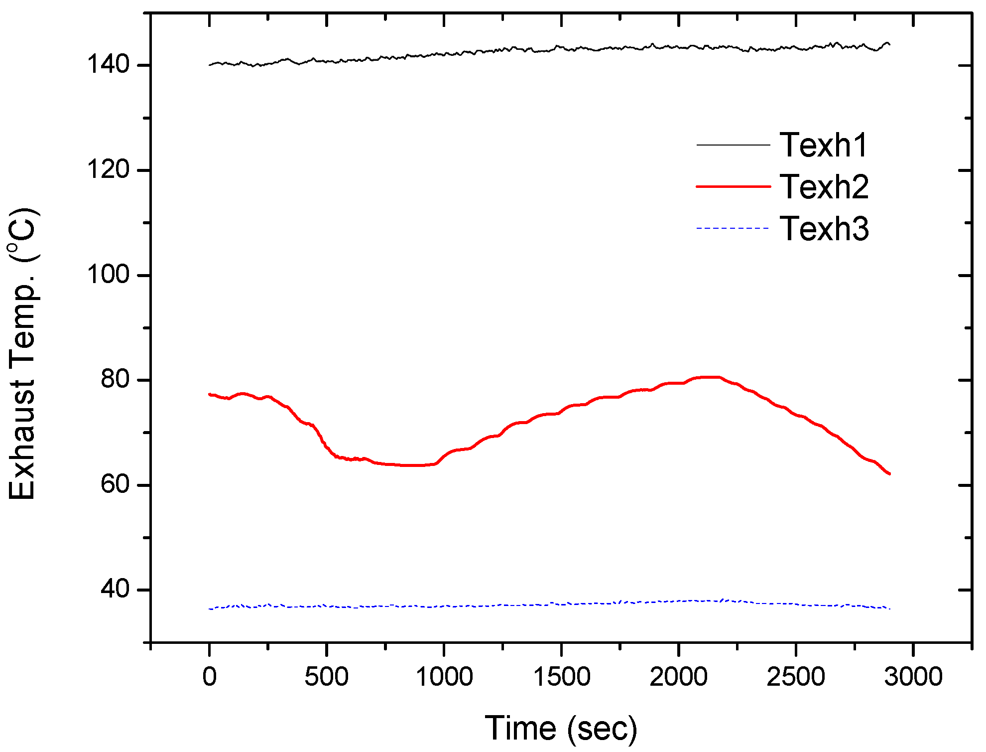
Figure 8 shows that with the increase and decrease in the evaporation (expander inlet) pressure, between 14 and 22 bar (between 750 s and 3000 s), the exhaust gas temperature after passing through the HT evaporator of the ORC unit (Texh2) with an inlet temperature (Texh1) of 143 °C increased and decreased symmetrically between 64 °C and 81 °C. In general, if the evaporation pressure of the ORC for waste heat recovery from the flue gas increases, the outlet temperature of the flue gas from the ORC also increases, and the quantity of heat recovery decreases [
21,
22].
To minimize the effect of the stored thermal energy of the heat exchanger during the early stages of the experiment, and check the reproducibility of the experiment, the experimental results, as shown in
Figure 9, were selected for further analyses in the range of 750 s to 3000 s.
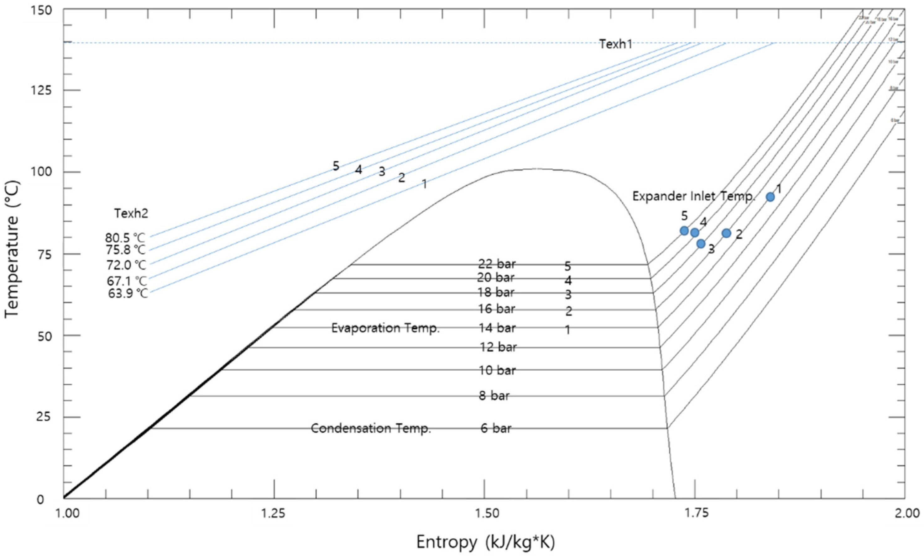
Figure 10 shows the operating conditions of the system, with an increasing evaporation pressure in the temperature and entropy diagrams. The outlet temperature of the exhaust gas from the ORC unit (Texh2) linearly increased with an increase in the evaporation pressure between 14 and 22 bar (from conditions 1 to 5).
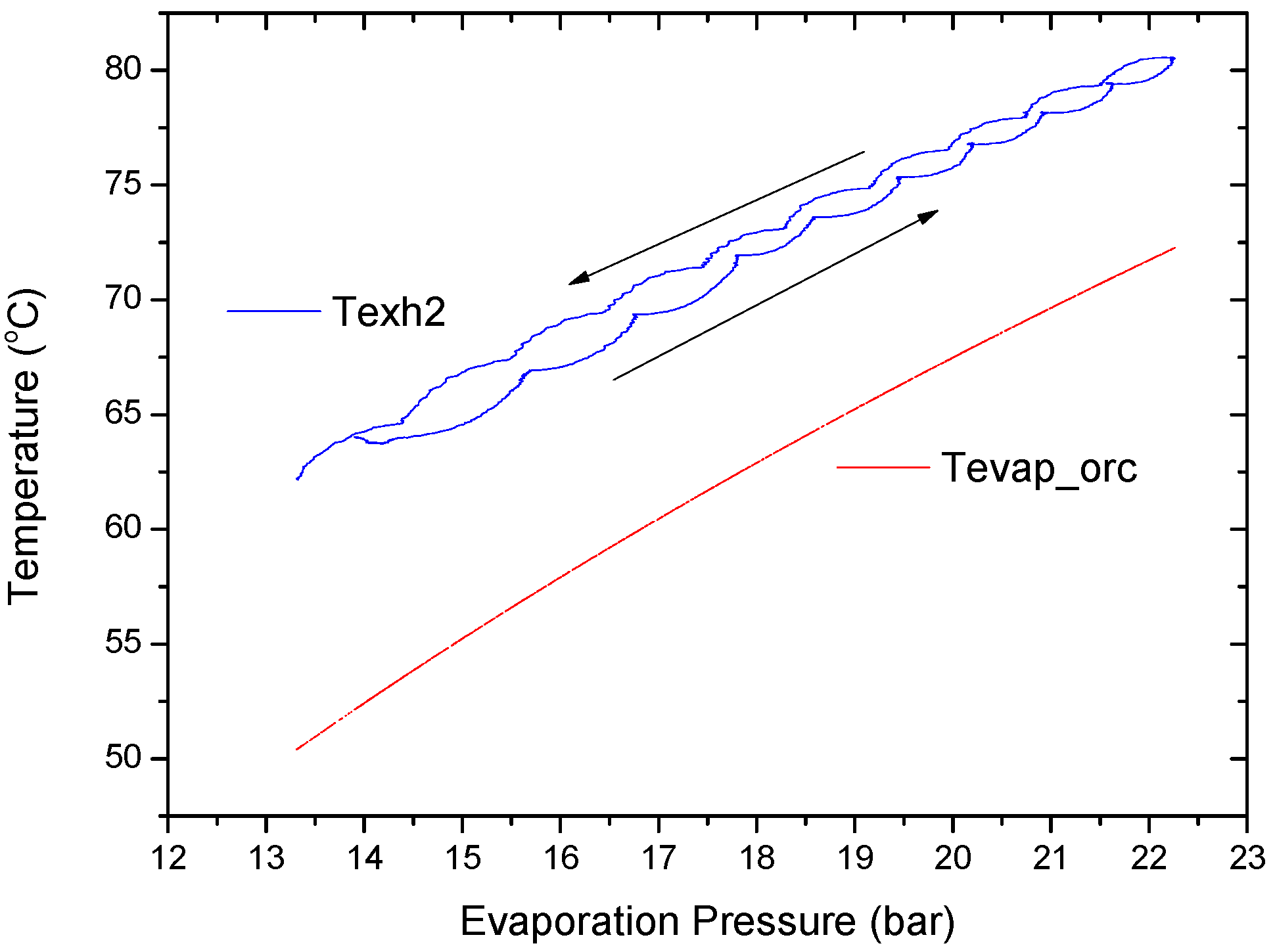
Figure 11 shows the relationship between Texh2 and the evaporation temperature of the ORC (Tevap_orc) with an increasing evaporation pressure, in which Texh2 increased and decreased reversibly with the evaporation temperature of the ORC, along with a variation in the evaporation pressure.
Figure 11 clearly shows the decrease in the heat input from the HT evaporator with an increase in the evaporation pressure of the ORC.
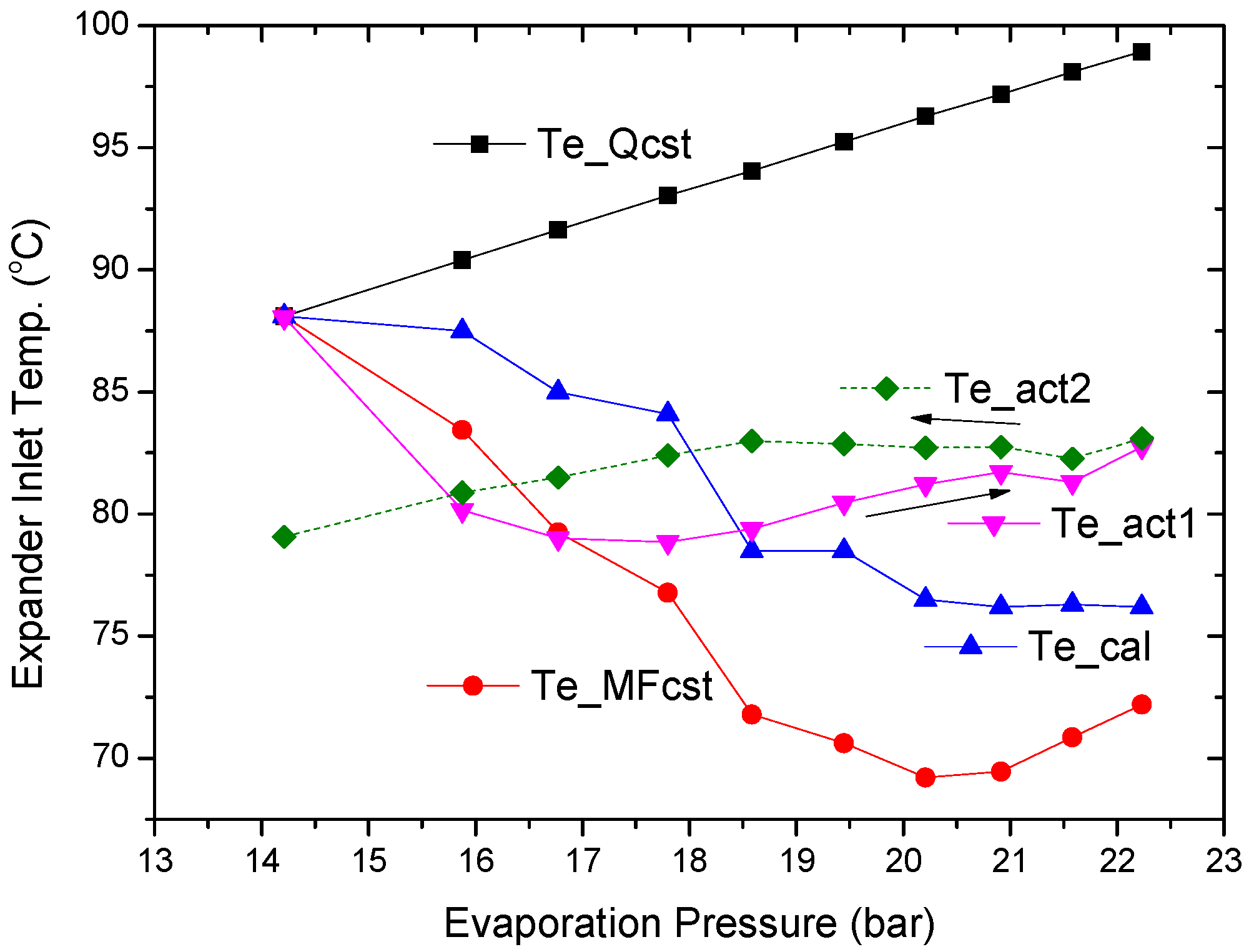
Figure 12 shows the analyses of the expander inlet temperature with an increase in the evaporation pressure between 14 and 22 bar. If the heat input into the ORC is constant, the expander inlet temperature (Te_Qcst) increases with an increase in the evaporation pressure. However, if the decreased heat input from the HT evaporator with an increase in the evaporation pressure of the ORC is applied with a constant mass flow of the ORC working fluid, the expander inlet temperature (Te_MFcst) decreases with an increase in the evaporation pressure. In the experiment, when the pump speed was kept constant, the measured mass flow rate of the ORC working fluid slightly decreased with an increase in the evaporation pressure. The calculated expander inlet temperature (Te_cal) with the decrease in the heat input from the HT evaporator was plotted between Te_Qcst and Te_MFcst. In addition, the actual expander inlet temperature with the increase and decrease in the evaporation pressure (Tact1 and Tact2, respectively) was plotted with the calculated expander inlet temperature (Te_cal), in which there were some deviations observed due to the measurement errors (temperature, pressure, mass flow rate, etc.) and the unsteady state.
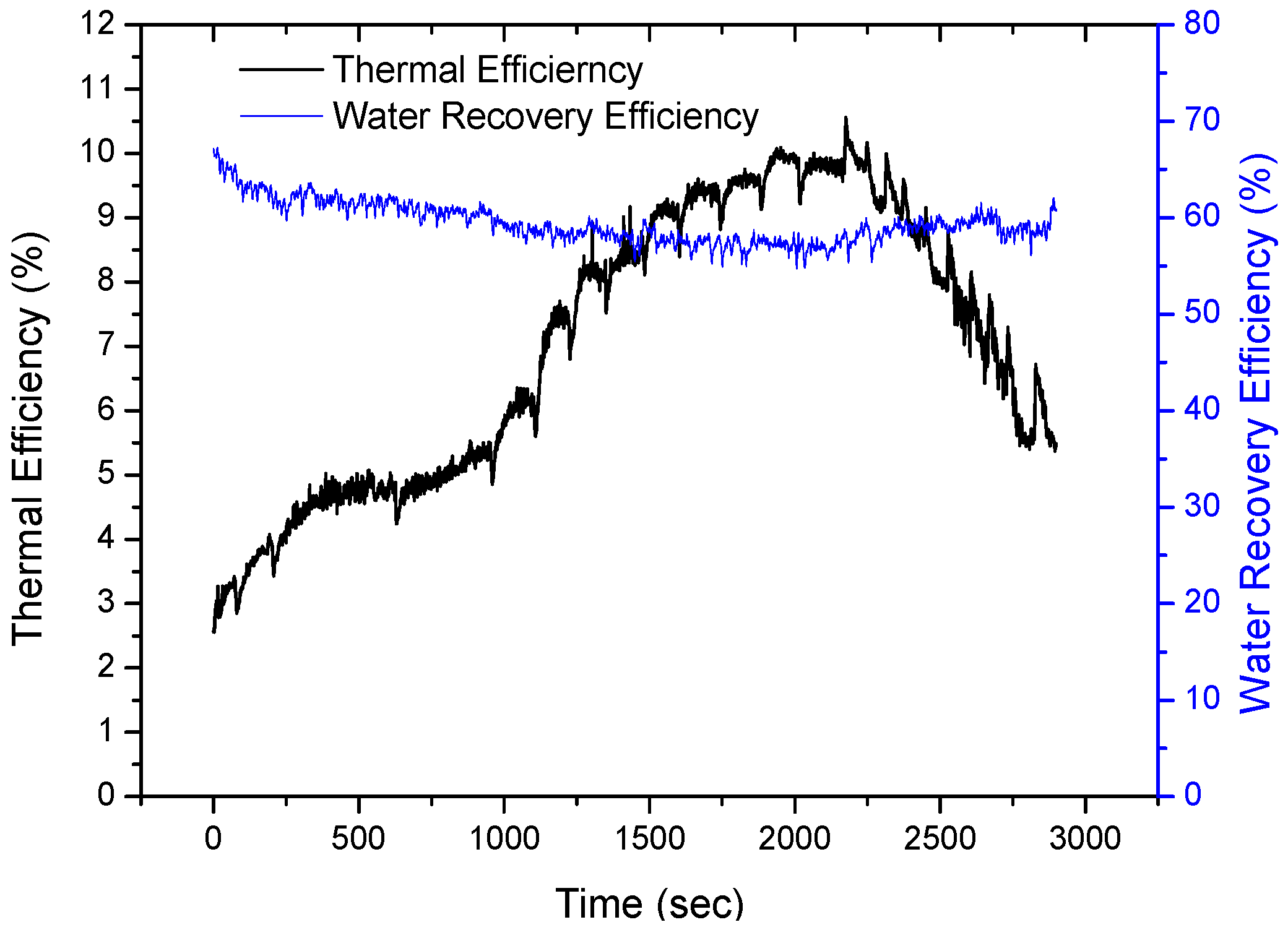
As shown in
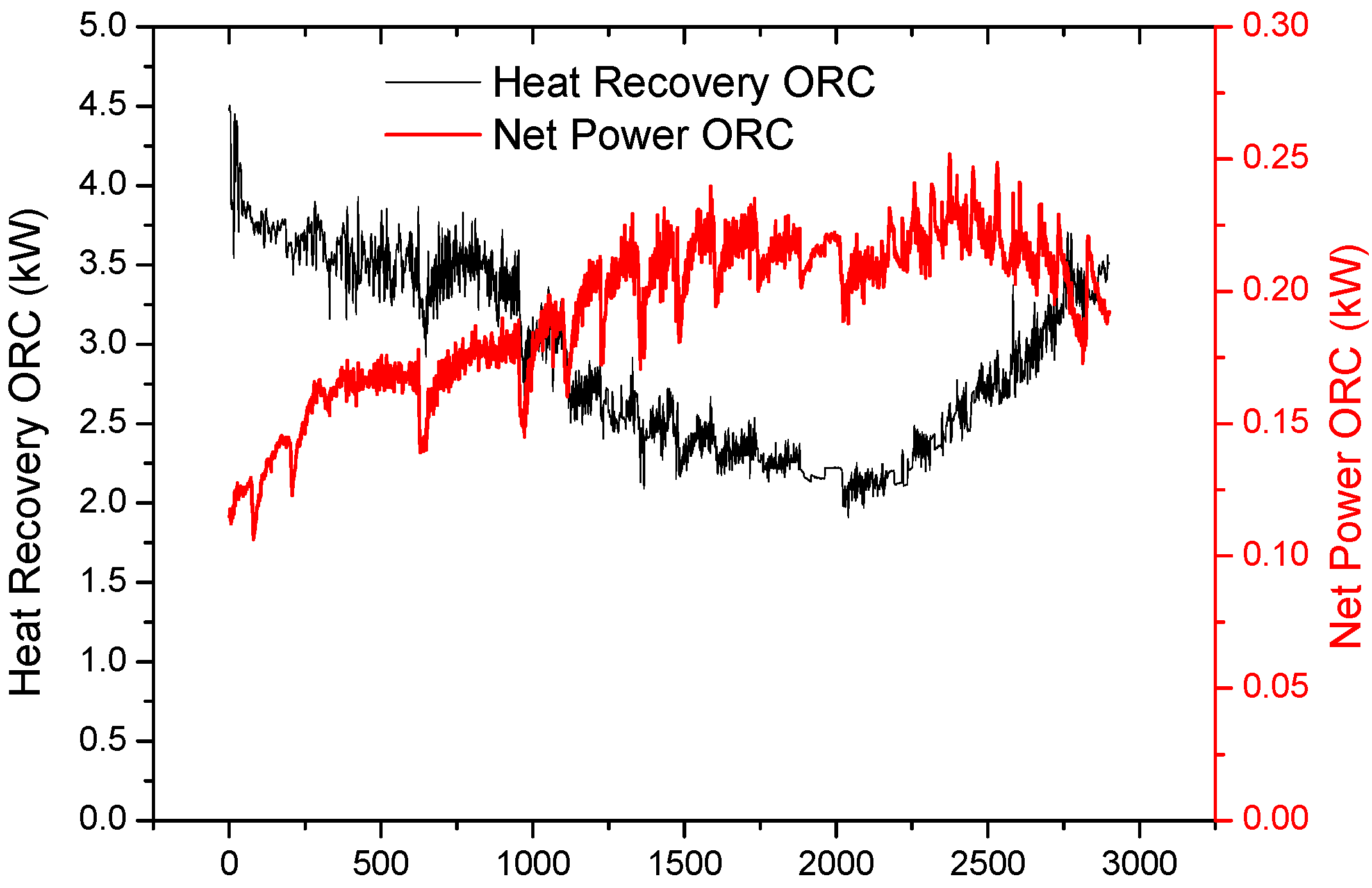
Figure 13, with an increase in the evaporation pressure between 10 and 22 bar, the thermal efficiency increased continuously from 3% to 10% (with a maximum uncertainty of ±0.15%); however, the heat input from the HT evaporator of the ORC unit decreased from 3.5 kW to 2.1 kW (with a maximum uncertainty of ±0.05 kW), as shown in
Figure 14. The abnormal temperature decrease of Texh2 during the early stage of the experiment between 0 and 750 s was attributed to the thermal inertia of the heat exchangers, because their stored thermal energy could be used to heat the working fluid. Thus, the heat exchangers could be cooled, because the abnormal temperature decrease of Texh2 during the early stages of the experiment in the range of 0 to 750 s did not increase the heat input from the HT evaporator of the ORC, as shown in
Figure 14.
Therefore, the net power of the ORC unit increased from 115 to 220 W in the range of 10 to 18 bar (evaporation pressure), and then decreased to 200 W in the range of 18 to 22 bar (condensation pressure). The optimal evaporation pressure for the maximum power obtained from the experimental results was approximately 18 bar. Consequently, the maximum power output from the given waste heat source can be obtained by incorporating both the heat recovery efficiency (heat input from the given waste heat source) and thermal efficiency (net power from the heat input) of the ORC [
21,
22].
With an increase and decrease in the evaporation (expander inlet) pressure, as shown in
Figure 15, the water recovery efficiency decreases and increases from 58% to 62%, because the temperature of the exhaust gas after the LT evaporator of the water recovery unit (Texh3) increased and decreased in the range of 36 °C to 38 °C, owing to the increase and decrease in the exhaust gas after the HT evaporator of the ORC (Texh2), as shown in
Figure 8. The relative inlet humidity at 143 °C was 3.6% (the partial pressure ratio of water vapor being 14.4%), and the relative outlet humidity at 37 °C was 90.0% (the partial pressure ratio of water vapor being 5.8%). Therefore, the calculated water recovery efficiency was 60.0% (maximum uncertainty, ±6.6%). The flue gas, with an initial temperature of 143 °C, was cooled to 79 °C through the HT evaporator, and further cooled to 37 °C using an LT evaporator. However, the heat recovery through the HT and LT evaporators was 2.3 kW (max uncertainty of ±0.05 kW) and 18.2 kW (max uncertainty of ±0.12 kW), respectively, because the temperature drop was small through the LT evaporator; however, the latent heat owing to water condensation accounted for the large heat recovery.
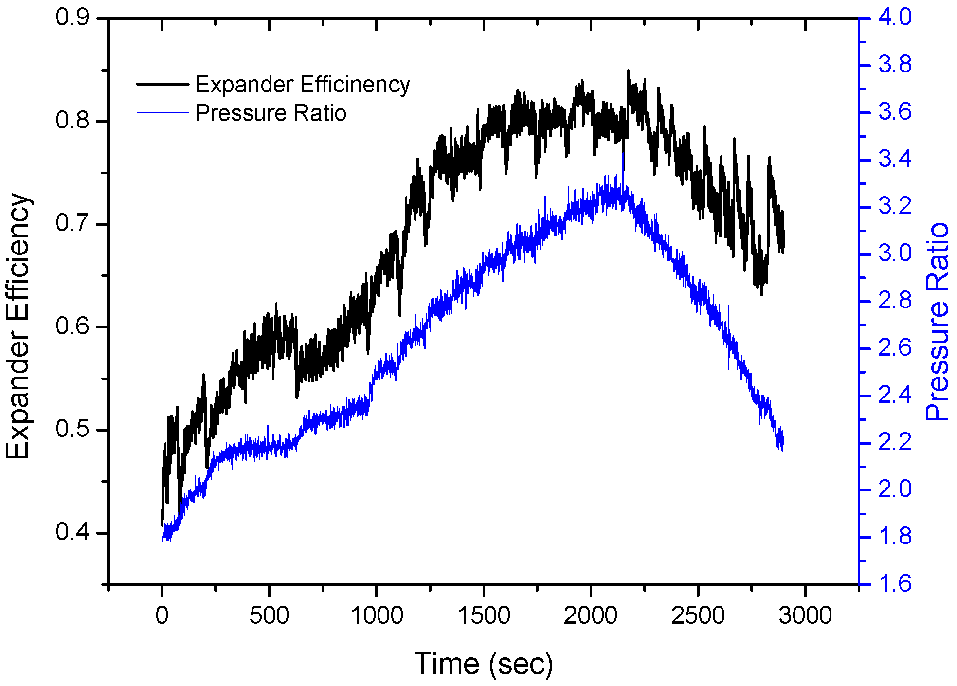
With an increase in the evaporation (expander inlet) pressure, the thermal efficiency of the ORC increased significantly, from 3% to 10%. This was partly due to the increase in the evaporation pressure of the ORC, and as shown in
Figure 11, the expander efficiency increased significantly from 45% to 80% (max uncertainty of ±1.3%) with an increase in the pressure ratio from 1.8 to 3.2, approaching the design pressure ratio of 3.5.
6. Conclusions
Heat and water recovery from the flue gas by condensing the flue gas moisture in a thermal power plant can help to reduce CO2 emissions, water requirements, condensable PM, and the occurrence of white plumes and smog around the power plant. After a preliminary study, a WHWR system composed of an ORC and cooling cycles that uses a single working fluid accompanied by a phase change was proposed and optimized for a 600-MW power plant with water vapor with a volume of 16% in flue gas at 150 °C.
In this study, a lab-scale system for heat and water recovery from the flue gas of a steam boiler was built and tested. First, the low thermal efficiency of the ORC unit resulted from the mismatch between the low flow rate of the flue gas and the large capacity of the expander of the ORC unit. Therefore, an additional working fluid (R134a) heated by steam from the boiler was added to the inlet of the expander in order to achieve high-efficiency conditions of the ORC unit, where the power from the waste heat recovery of the flue gas was calculated by the portion of the working fluid that passed into the expander.
With an increase in the evaporation (expander inlet) pressure from 10 to 22 bar, the thermal efficiency of the ORC increased significantly from 3% to 10%. This was partly due to the increase in the evaporation pressure of the ORC, and the significant increase in the expander efficiency, approaching the design pressure ratio of the expander. However, the heat input from the HT evaporator of the ORC unit decreased from 3.5 to 2.1 kW. The optimal evaporation pressure for the maximum power from the experimental result is approximately 18 bar, because the maximum power output from the given waste heat source can be obtained by incorporating both the heat recovery efficiency (heat input from the given waste heat source) and thermal efficiency (net power from the heat input) of the ORC.
At the optimized conditions, the flue gas with an initial temperature of 143 °C was cooled to 77 °C through the ORC evaporator, with a heat recovery of 2.3 kW, generating an additional power of 220 W, with a thermal efficiency of 9.4%. Subsequently, the flue gas was further cooled to 37 °C through the pumped HPC evaporator, with a heat recovery of 18.2 kW, producing condensed water with a water recovery efficiency of 58%.


