1. Introduction
Power cables have been widely used in urban power systems, and their safe operation is key to the reliability of the power grid [
1]. Cable accessories, which are used to connect cables with other electrical equipment or different sections of cables, are the weak links of cable systems [
2]. Reference [
3,
4] indicated that the manufacturing of fault-free cable accessories is almost impossible, and poor workmanship during installations and design defects may result in cable faults. Previous studies showed that when there exist defects in cable accessories, such as poor contact of metal connectors, misalignment of stress cones, damage of insulation layer or impurities, and bubbles in the internal medium, the temperature of defective cable accessories was usually higher than those fault free cable accessories [
5]. Because the use of infrared thermography to identify abnormal temperatures has many advantages, such as no physical contact, non-intrusive, high efficiency, and so on, it is widely used in inspection and maintenance activities of power cable circuits [
6]. At present, the processing and analysis of infrared images taken during inspections mainly require visual inspection. This is time-consuming and laborious on the one hand, and on the other hand, it relies too much on expert experience and is prone to erroneous diagnosis. Therefore, the realization of autonomous condition diagnosis in cable accessories would greatly benefit the practitioners involved in cable maintenance and inspections.
In previously published researches, the image features related to the temperature gradients of equipment were used as the input of neural networks for the autonomous diagnosis of electrical equipment. In order to analyze the temperature-related information, Rahmani et al. used the Zernike moment as an image feature of fuse bases [
7]; Huda et al. extracted the first-order histogram and gray level co-occurrence matrix of infrared images captured from main switchboards [
8,
9,
10]; Jaffery et al. extracted the RGB color moment of images of fuse cabinets [
11]. In the above studies, the key features needed to be selected manually, which was, in fact, a heuristic process. The quality of the selected features was largely dependent on human expertise.
Thus far, there have been few studies on the recognition of infrared images for condition diagnosis of cable accessories. Previously reported research came from the same research team where a number of techniques were investigated for infrared image processing of cable terminations, including the adaptive denoising method based on layer-by-layer optimal basic wavelet and Bayesian estimation [
12], the denoising method based on inter-scale correlation of the wavelet coefficients and the bivariate shrinkage function [
13], the improved hybrid Fourier-wavelet denoising method [
14] and the identification method based on the Radon transform and the Fourier–Mellin transform [
15]. Although the above methods were proven to be effective in preliminary image processing, the published work failed to carry out condition diagnosis of real-world infrared images.
This paper proposes a method for autonomous diagnosis of overheating defects in cable accessories based on a Faster RCNN network and Mean-Shift algorithm. Firstly, the collected infrared images of cable accessories during routine inspection activities are used as samples to complete the training of the Faster RCNN network thus as to identify and locate the objects to be diagnosed. Then, the Mean-Shift clustering algorithm is used to segment the images. This helps to extract the overheating area quickly and accurately. Finally, the temperature characteristic parameters are calculated, thus the condition of cable accessories can be diagnosed according to pre-set diagnostic criteria.
2. Object Localization Based on Faster RCNN Network
Cable accessories of interest in this paper include cable terminations and cable grounding boxes. For more information, readers may refer to [
16,
17]. For the FLIR T630 thermal imager, a handheld camera, which has been applied in work presented in this paper, does not have a specified minimum and maximum shooting distance. When we applied it, the distance between the camera and the target was usually between 1 and 10 m. It was around 1 m when pictures were taken of cable joints and was 3–10 m for cable terminations. As a result, the infrared images under analysis may contain the targeted cable accessories and may also contain other undesired background objects.
The Faster RCNN network, which can identify and locate the desired objects contained in given images, is one of the most advanced algorithms for target detection.
Figure 1 shows the flowchart of the Faster RCNN network. Firstly, in order to produce the feature map, it extracts the features of the detected image through a Convolutional Neural Network (CNN). Then, the Region Proposal Network (RPN) is used to propose the possible regions. Next, on the basis of the feature map and proposed regions, the Region of Interest (RoI) pooling layer is applied to extract the proposal feature maps, which are sent to the subsequent network. Finally, the autonomous recognition and positioning of the objects are realized through the object detection layer [
18].
2.1. Sturcture of Faster RCNN Network
2.1.1. Convolutional Neural Network
Convolutional Neural Network is used to extract feature maps of input images, and the feature maps are shared with the subsequent RPN network and RoI pooling layer. In this paper, the VGG16 Convolutional Neural Network, which includes 13 Convolutional (Conv) layers, 13 Rectified Linear Units (ReLU) layers, and 4 Pooling layers, shown in
Figure 2, is adopted.
Convolutional layers are applied to detect features of images. It is composed of several convolutional kernels (equivalent to weight matrix
k) and additive bias
b. Each convolutional kernel can be regarded as a kind of feature detector, which filters the whole image by sliding on the image to capture the corresponding features. From the mathematical point of view, the corresponding features are obtained through the convolutional operation. Suppose the
mth layer is a Convolutional layer, then its output vector is as follows:
where
is the
jth output of this layer;
Mj is the set of input vectors;
is a convolutional kernel;
is the additive bias, and * represents the convolutional operation.
The size of the output image is as follows:
where
soutput represents the size of the output image;
sinput represents the size of the input image;
skernel represents the size of the convolutional kernel;
p represents the number of pixels to be filled, and
d represents the step length of the convolutional kernel sliding on the image.
After each convolutional layer, the ReLU layers are applied to enhance the nonlinear characteristics, and the ReLU function is given in (3). Between the Convolutional layers, the Pooling layers are inserted periodically to reduce the dimensionality of features.
where
f(
x) stands for the ReLU function, and
x represents the characteristic parameters of the output of the convolutional layer.
2.1.2. Region Proposal Network
The Region Proposal Network is used to complete the preliminary positioning of the objects. As is shown in
Figure 3, the Region Proposal Network firstly generates a set of rectangular bounding boxes in the detected image. These regions are represented by four-dimensional vectors (
x,
y,
w,
h), where
x and
y denote the region’s center coordinates, while
w and
h denote the width and height. Then, the classification layer is applied to obtain the object score of each proposed region, based on which the Softmax classifier is used to identify the regions that include the diagnostic objects by calculating the probability, using the formula given in (4). On the other hand, to make the positioning more accurate, the regression layer is applied to realize the bounding box regression, based on the formulae given in (5) and (6).
where
P represents the probability that the proposed region contains diagnostic objects;
z1 and
z2 represent the foreground score and background score of proposed regions, respectively.
where (
Ax,
Ay,
Aw,
Ah) denote the unadjusted coordinates of the bounding box. (
G’x,
G’y,
G’w,
G’h) denote the adjusted coordinates.
dx(
A) and
dy(
A) denote the translation parameters,
dw(
A) and
dh(
A) denote the scale parameters.
2.1.3. Region of Interest Pooling Layer
The RoI Pooling layer can obtain the fixed-length feature vectors by analyzing input data of different sizes. The operating principle is shown in
Figure 4. Assuming that the size of input feature map is 8 × 8, and the box calibration region is the proposed feature. According to the transformation factors
pw and
ph, the proposed feature is divided into
pw ×
ph blocks (
pw =
ph = 2 in this example). Then the maximum pooling is applied for each block in order to the maximum value of each block.
In the Faster RCNN network, the pooling process of the RoI Pooling layer is shown in
Figure 5. Firstly, the regions proposed by the RPN are mapped to the feature map obtained by the CNN, to allow the proposal feature maps of different sizes to be extracted. Next, according to
pw and
ph (
pw =
ph = 7 in this paper), maximum pooling is applied to convert the proposal features into feature maps with the fixed spatial extent of 7 × 7. Finally, the fixed-length proposal feature maps are sent to the subsequent network.
2.1.4. Object Detection Layer
As is shown in
Figure 6, based on the proposal feature maps, the Softmax classifier is used to achieve object identification (objects to be identified include cable terminations and grounding boxes in this paper). On the other hand, the regression layer is applied to complete the second bounding box regression, which makes the localization more precise.
2.2. Autonomous Detection Results of Faster RCNN Network
The infrared images captured by the infrared thermal imagers (FLIR T630) were used as samples to train the Faster RCNN network.
Table 1 shows the specifications of the FLIR T630 handheld thermal cameras. When the infrared images of power cable accessories were taken, the emissivity coefficients of imagers were set to 0.9.
The abnormal heating phenomenon usually occurs at connection fittings and sleeves of the cable terminations or the connections of the grounding boxes. Therefore, when constructing the training samples, if the diagnostic objects are the terminations, the labeled target should be the connection fittings and sleeves. If the objects under analysis are grounding boxes, the marked target should be the connections. After completing the training, the Faster RCNN network can realize the autonomous identification and positioning of the cable terminations and grounding boxes in images.
Taking
Figure 7 and
Figure 8 as examples, where
Figure 7a and
Figure 8a, respectively, show the original infrared images of grounding box and cable termination taken during routine inspection activities.
Figure 7b and
Figure 8b show the recognition and positioning results of the trained Faster RCNN network. To eliminate the influence of the interference information, the image contents inside the proposal regions were kept, while other contents were eliminated by setting the pixels’ components of red (R), green (G), and blue (B) to zero. The extracted connections of the grounding box are shown in
Figure 7c. The extracted connection fitting is shown in
Figure 8c, and the extracted sleeve in
Figure 8d. The results show that based on the Faster RCNN network, the diagnostic objects were accurately extracted, and the interference of complex background and foreground, which my hamper subsequent image processing, were eliminated.
3. Extraction of Suspected Abnormal Heating Regions Based on Mean-Shift Algorithm
After extracting the diagnostic objects, it is necessary to extract the suspected abnormal heating regions among the objects. In subsequent processing, their temperature distribution is the basis for condition diagnosis.
The gray information of the infrared images reflects the temperature distribution. The greater the gray value of the pixel, the higher the corresponding temperature. Therefore, the gray value is to be extracted from the infrared images. The graying formula is as follows [
19]:
where,
I is the gray value of the pixel;
R is the red component;
G is the green component, and
B is the blue component.
The Mean-Shift algorithm, which has been widely used in clustering, is essentially an iterative search algorithm [
20]. In this paper, the gray values of pixels were used as the data samples, and the Mean-Shift algorithm was applied to cluster the pixels. The clustering process is shown in
Figure 9. Firstly, a pixel was randomly selected to be the clustering center, and other pixels, of which the grayscale difference with the center less than the bandwidth, were placed in the same class. The bandwidth
hr realized adaptive selection based on the asymptotic mean integrated square error (AMISE) is as shown in (8) and (9) [
21]. Then, the Mean-Shift vector was calculated, and the original center moved the vector to obtain the new center [
22]. The clustering center was updated until the convergence condition was satisfied. The above steps were repeated until all the pixels were traversed.
where,
hr represents the bandwidth;
d the dimension of the feature space;
n the number of samples;
σ the standard deviation;
x the sample, and
represents the average value of the sample data.
In order to describe the Mean-Shift clustering process more intuitively, this paper takes the cable grounding box as an example, as is shown in
Figure 10.
Figure 10a shows the result of autonomous positioning and identification of the diagnostic objects (connections) in infrared images by trained Faster RCNN network.
Figure 10b shows the corresponding grayscale image.
Figure 10c shows the three-dimensional visualization result of the pixels’ gray information, where each scatter point corresponds to a pixel in the image, (
x,
y) represents the position information of the corresponding pixel in the original image, and
z represents the gray value of the pixel.
Figure 10d shows the result of clustering by the Mean-Shift algorithm. In order to reflect the clustering result more intuitively, the pixels belonging to the same category were marked with the same color.
As can be seen in
Figure 10d, the pixels in the example were adaptively divided into three categories. The pixels marked in black correspond to the background area in the original image. The pixels marked in green correspond to the regions under normal conditions, and the pixels marked in red correspond to the suspected overheating regions. Therefore, after clustering based on the Mean-Shift algorithm, this paper retained the category with the center, where the gray value was the greatest, as the suspected overheating area.
Taking the infrared images of the HV cable accessories captured during an inspection as the testing objects. In order to achieve the best results, after realizing the autonomous identification and positioning of the diagnostic objects, this paper, respectively, applied the Maximum Between-Class Variance (OTSU) algorithm, the K-Means algorithm, and the Mean-Shift algorithm to segment the images. The OTSU algorithm can adaptively calculate the segmentation threshold, and the pixels of which the gray values are lower than the threshold were categorized into the background, while other pixels, of which the gray values are higher than the threshold, were categorized into the foreground [
23]. The K-Means algorithm randomly selected
k pixels as clustering centers according to the given
k, and then classified the remaining pixels to the most similar center before it updated the clustering centers to the mean value of each category. The above steps were repeated until the convergence condition is satisfied [
24,
25].
Based on the clustering results, the suspected abnormal heating regions were extracted, as is shown in
Figure 11.
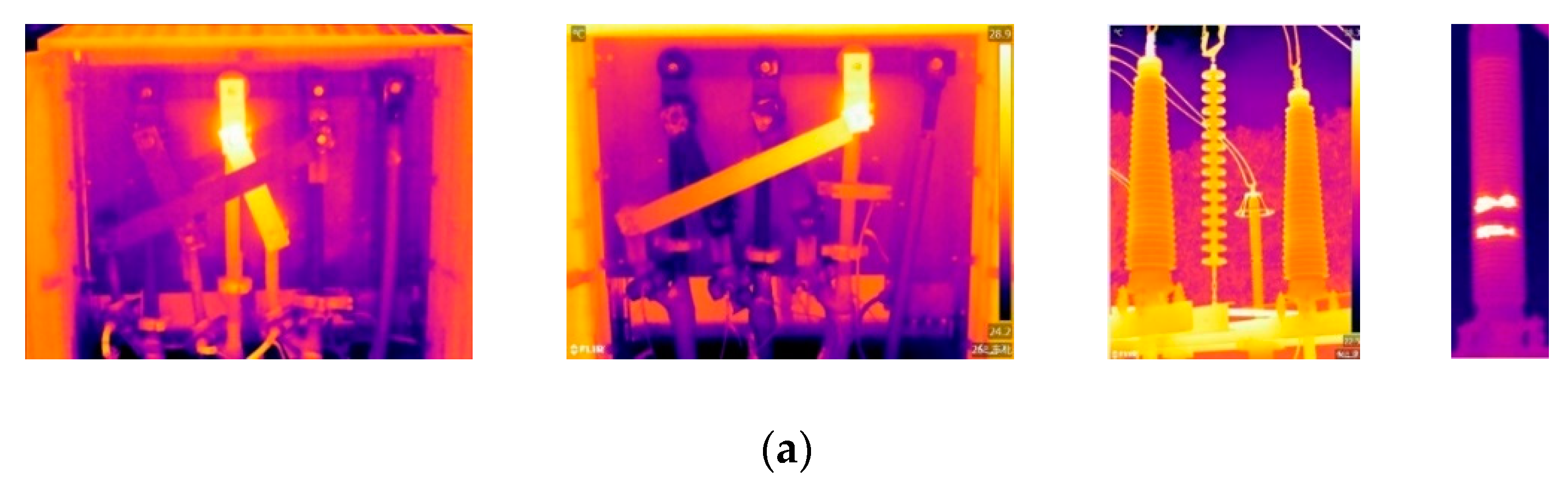
Figure 11a shows the original infrared images of grounding box I, grounding box II, termination I, and termination II.
Figure 11b shows the detecting results of diagnostic objects by the Faster RCNN network.
Figure 11c,
Figure 11d,e show the extracting results of suspected abnormal heating regions by different clustering algorithms.
As shown in
Figure 11, the adaptive segmentation threshold calculated by the OTSU algorithm was often too low to distinguish the abnormal heating regions from the area under normal conditions. Thus, in the final segmentation results, the abnormal heating area was almost submerged in the diagnostic objects. The K-Means algorithm can specify the number of categories manually, which solves the disadvantage of the OTSU algorithm that it can only achieve dichotomy. Therefore, compared with the OTSU algorithm, the clustering results by K-Means algorithm represented an improvement. However, for different images, the most suitable number of clustering categories is also different. Thus, some regions under normal conditions were still identified as abnormal heating regions wrongly by the K-Means algorithm. The Mean-Shift algorithm can adaptively select the most appropriate number of clustering categories according to the gray information of the image, which can overcome the disadvantage of the K-Means algorithm. The testing results showed that the Mean-Shift algorithm could extract the abnormal heating regions accurately, and its performance was better than the OTSU algorithm and the K-Means algorithm.
5. Calculation of Temperature Parameters and Condition Diagnosis
In order to diagnose the severity of the overheating defect,
T1 and
T2, which denote the maximum temperature of the identified abnormal heating area and reference area, respectively, were extracted. Combined with the ambient temperature
T0, the temperature characteristic parameters can be calculated according to (12)~(14).
where
Tr is the value of temperature rise;
Td is the value of temperature difference, and
δ represents the value of relative temperature difference.
According to the corresponding diagnostic criteria, the autonomous diagnosis of overheating defects in cable accessories can be achieved based on the calculated temperature characteristic parameters.
Table 2 shows the diagnostic criteria from the “Guidelines for defective grading standards of power transmission equipment of Guangdong Power Grid Company (version 2018)”.
Table 3 shows the calculated temperature parameters and diagnosis results of
Figure 12 and
Figure 13. The temperature difference of grounding box I in
Figure 12 was 6.4 °C. Because it was between 5 °C and 15 °C, the status of grounding box I was regarded as the general defect. The temperature difference of grounding box II was only 2.9 °C, which was lower than 5 °C. In addition, the temperature rise was only 4.6 °C, which was less than 15 °C, the condition of grounding box II was diagnosed to be normal. Similarly, the temperature difference of connection fittings of cable terminations I in
Figure 13 was 50.6 °C, which was higher than 40 °C, thus the termination I was judged to have a defect needing urgent action. The temperature difference of sleeves of cable terminations II was 11.2 °C, thus the condition of this termination was determined as having a major defect.
The proposed method has been applied to test against actual infrared images, including 50 images of cable terminations and 50 images of grounding boxes. The testing results are shown in
Table 4.
6. Conclusions
This paper is an extension of a conference paper, which the authors previously published [
25]. It proposed an autonomous method to analyze infrared images for the diagnosis of insulation conditions of cable accessories. The approach included the positioning and identification of diagnostic objects, the extraction of key regions, and the calculation of temperature parameters for condition assessment of cable accessories. The conclusions are as follows:
(1) The method for autonomous positioning and identification of cable accessories in infrared images based on Faster RCNN network was proposed. This method was applied to test against actual infrared images, and results showed that the autonomous location and recognition could be achieved at different shooting angles and under various background conditions.
(2) The method for extracting suspected abnormal heating regions based on Mean-Shift algorithm was proposed. Case studies showed that this method, which was superior to other alternatives, can realize image adaptive segmentation. It can extract the abnormal heating regions of grounding boxes and cable terminations accurately.
(3) The proposed method may potentially be productive as it helps reduce the dependence on human efforts and expertise and helps improve the practice of intelligent condition monitoring.


