1. Introduction
Power utilities’ implementation of distribution automation (DA) and Internet of Things (IoT) may bring about many benefits, including providing a fast method to improve reliability and reducing power-outage time [
1]. IoT aids the smart grid to collect, monitor, and analyze the power grid’s status and performance [
2,
3]. Topology analysis is an important aspect of DA, being the basis for power flow calculations, state estimations, fault locations, and line loss reductions. Most distribution lines are radial [
4] and connect the substations to users. However, due to changes in user load, such as load growth, the structure of the distribution line needs to be modified. In addition, due to some faults, it is necessary to close or open the switchgear on the line during the operation, something which will also affect the topology of the distribution line. The topology information configuration and exchange of distribution lines are both important subjects in this field. In recent years, distribution protection and control systems have been of wide concern for the smart distribution grid. The distribution system is highly flexible and adaptable, characteristics that are more suited to the structural characteristics and operational requirements of intelligent distribution networks [
5,
6,
7,
8]. Some applications on intelligent electronic devices (IEDs) require topology information and exchange of topology information. Thus, the configuration and analysis of the distribution line topology in distributed systems is a topic that is being widely researched currently.
The description of the topological model needs to be standardized in order to facilitate information sharing. The International Electrotechnical Commission (IEC) technical commission (TC) 57 has undertaken a lot of work to facilitate the description of the power grid information model, as well as the interconnection of equipment and systems from different manufacturers. IEC TC 57 has established IEC 61970, 61968, and 61850, among other standards, and standardized the information model and information exchange model. IEC 61970 and IEC 61968 are used for information sharing between master station systems. IEC 61850 is mainly used for information sharing among field IEDs, although now IEC 61850 is also a commonly used communication standard in smart grids, such as in micro grids [
9,
10], for projection [
11,
12], and for electric vehicle management [
13]. So, the description and information exchange of the distribution line (feeder) topology need to refer to the above three standards.
The distribution feeder is an important concept to describe the topology of the distribution network. A feeder is one of the circuits out of the substation, which includes symmetrical three-phase lines and asymmetrical two-phase and single-phase lines. When viewed logically, then, a feeder constitutes a collection, and specifically, a collection of equipment for organizational purposes that is used for grouping distribution resources [
14]. Any given feeder is made up of a main feeder, branches or laterals, and sub-laterals. It is usually sectionalized by reclosing certain devices and protected by fuses [
15]. Reference [
16] proposed a feeder-oriented method to be used to carry out a topology analysis of a medium-voltage (MV) distribution grid. Reference [
17] proposed that information models (including the feeder) be used to facilitate information integration between the distribution network production repair platform (DNPRP) and other IT systems. The latest IEC 61970 common information model (CIM) (IEC61970 CIM 17v38) adopts the feeder model. Meanwhile, the description language to be used for the system configuration language (SCL) of IEC 61850 is generally also used for the topology configuration. In References [
18,
19], the SCL process and line models are used to describe the distribution grid topology. Moreover, Chen [
20] uses a logical node to express the topology for both the feeders and for information exchange between IEDs. Cong [
21,
22], meanwhile, used a distribution method to store the feeder topology. Reference [
23] configures the feeder’s adjacent switches based on a user-defined format. In References [
24,
25], a local topology based on smart terminal unit (STU) storage is proposed, and then, through an STU query on the real-time feeder topology, it realizes the STU itself.
With the increase in distributed applications, it is necessary for IEDs to exchange feeder topology information, especially runtime topology information. There is no solution for topological information exchange in IEC 61850. Therefore, this paper proposes a topology information exchange mechanism using logical nodes. Experiments are carried out to verify the effectiveness of the method. According to the characteristics of the MV and low-voltage (LV) distribution grid, combined with the information models IEC 61970 and IEC 61850, we propose a topology configuration method based on the feeder model. To facilitate the exchange of topology information between the IEDs, the logical nodes from both the connectivity and topological nodes are added. The subsequent sections of the paper are ordered as follows:
Section 2 discusses the physical structure of the feeder;
Section 3 presents the feeder’s logical model; in
Section 4 and
Section 5, the logical nodes are added to the connectivity and topology models in order to facilitate information sharing between the IEDs; and, finally,
Section 6 presents the summary of the study and provides insight for future work.
2. Physical Structure of the Feeders
2.1. Feeder Model
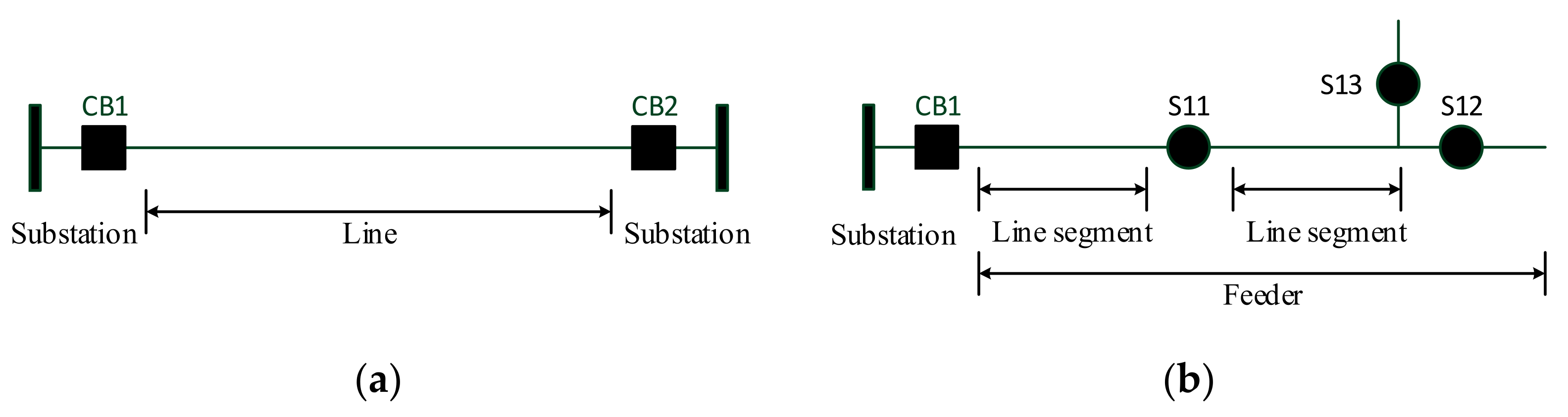
There are obvious differences between the transmission lines and distribution lines. The transmission line is generally connected to two substations, with the material and size of the line being the same. Additionally, there is no switchgear in the middle of the line, as seen in
Figure 1a. Generally, when analyzing the transmission line, it is considered to be a section of the conductor, but the distribution line is different, with the distribution line including a switch, load, and distributed generation. Within the distribution grid, the term “feeder” is more commonly used than the term “line”. Therefore, in this paper, the distribution lines will be referred to as feeders. A feeder, as specified in the IEC 61970 Part 301 CIM [
26], is a static collection of conducting equipment that originates from the main distribution center and supplies one or more secondary distribution centers, one or more branch-circuit distribution centers, or any combination of these two types of equipment. The feeder is divided into several sections, as shown in
Figure 1b, but the key part is the feeder section. Besides this, a feeder may also have switch devices, MV/LV distribution transformers, capacitors, and line voltage regulators, among other components. In addition, the transmission line is three-phase symmetrical; that is to say, it has the same voltage, load, and line impedance. It thus further resembles a single-phase circuit rather than a three-phase circuit. Though the distribution feeder has both single-phase and two-phase loads, many distribution loads are three-phase asymmetric and work in three phases. Therefore, we also need to carry out an asymmetric analysis approach on the distribution feeders.
According to the function and voltage level, feeders can be divided into MV feeders and LV feeders. A MV feeder is also known as a primary feeder, and is usually 600 V to 35 kV, while in China it is mainly 10 kV and 35 kV. The primary feeder obtains electric energy from the substation and distributes it to the end user. When close to each end user, a distribution transformer steps down the current to an LV secondary feeder (380Y/220 V in China).
2.2. Primary Feeder
A typical MV feeder is three-phase with symmetrical loading, and as per standard three-phase circuits with symmetrical loading, the neutral wire carries almost no current. The neutral wire is therefore sometimes left out. Three-phase four-wire systems and three-phase three-wire systems are both common configurations for primary feeders, but the most common distribution primaries in North America are four-wire multi-grounded systems: three-phase conductors plus a multi-grounded neutral. In Europe and China, meanwhile, the three-phase three-wire systems are the most popular. In China, the neutral point of the MV distribution system has not been effectively grounded, and so a three-phase three-wire system is adopted. Utilities in China often design the primary feeder for 400 A but often allow an emergency rating of 600 A. Distribution circuits meanwhile come in many different configurations and circuit lengths.
A feeder is one of the circuits from the substation. The breaker or recloser in the substation is usually the feeder’s starting point, while the end point is the load, distributed generation, and tie switch (normally open switch), which are associated with another feeder, switching station, etc., as shown in
Figure 1b. The feeder is divided into several sections through section switches (as shown in S11 and S12). The feeder is regarded as a collection of equipment, though this does not consider the tower, foundation, stay wire, cross arm, etc., but only considers the conductor, distribution transformer, circuit breaker, disconnector, fuse, reactive power compensation device, etc.
2.3. Secondary Feeder
LV distribution feeders are also called secondary feeders. From the distribution transformer, the secondary feeders connect to the end user at the service entrance. This area is composed of different types of power cables, transformer units, and other equipment, with all equipment specifications and construction complying with current national standards. The voltage level of the LV distribution feeders in China is usually 380Y/220 V, while the connection modes are mainly radial, trunk, and ring. Moreover, the phase-to-phase voltage is 380 V, and the phase-to-neutral voltage is 220 V. In most cases, only one distribution transformer will supply the power to the customers, while the loads are usually at the end of the distribution network. The radius of the power supply in the city center usually measures less than 150 m.
The circuit going from the distribution transformer to the end user can be divided into two parts: mainline and lateral. The mainline is formed up of a common trunk line running from the distribution transformer to the customers’ buildings. The mainline is usually composed of overhead lines and underground cables with modestly large conductors, with those conductors normally used being 120 mm2, 150 mm2, and 185 mm2 aluminum conductors. The wires used for LV overhead lines are generally three-phase four-wire systems insulated with cross-linked polyethylene (XLPE), and these are then installed on outdoor poles. The distance between two conductors for overhead lines should not be less than 1000 m. Underground cables, meanwhile, are generally buried in underground cable trenches. Their LV cables are generally made of three-phase and four-wire, and cross-linked polyethylene-insulated power cables can be selected. One or more laterals will branch off from the mainline to the end users. These laterals may be single-phase, two-phase, or three-phase, and are normally fused to separate them from the mainline if they are faulty. LV cross-linked polyethylene copper-core insulated conductors are used for household connections. The conductor’s cross-section shall be selected according to the continuous current carrying capacity and voltage loss, which is generally 10 mm2, 20 mm2, etc.
3. Abstract Model of the Feeder
3.1. Feeder Supervisory Control and Automation
As a basic component of the smart distribution grid and DA, feeder automation (FA) realizes the fault detection, location, and isolation of the distribution feeders, as well as the restoration of power supply in those sections deemed safe. Distributed feeder automation (DFA), meanwhile, is an automation mode that is independent from the master station. The communication network and the distribution terminals on the feeder communicate with each other to collect any fault information regarding the adjacent switches. Then, following a comprehensive comparison, the relevant fault section is judged. The switches at both ends of the section are first tripped to complete the fault isolation action. Then, the safe section’s power supply is restored by closing the tie switch. Finally, the processing results are reported to the main distribution station’s system. Distributed control is an especially suitable system for the distribution grid: the feeder is generally bounded by the MV bus in the substation; the number of control nodes will not be excessive; and the structure and algorithm design of the control system is relatively simple. In distributed control systems, it is necessary to configure the distribution lines model within the control range and exchange topology information in real time according to changes in the section switch.
In recent years, the development of power utilities has made great strides in the monitoring and management of LV power grids. The application of automatic meter readings and line loss management systems has improved the level of LV power grid monitoring, improved power quality for end users, and reduced the loss of LV feeders. To realize these functions, however, a large number of distributed monitoring terminals must be installed, and the LV feeder topology’s configuration and information exchange are required.
3.2. Feeder Information Model
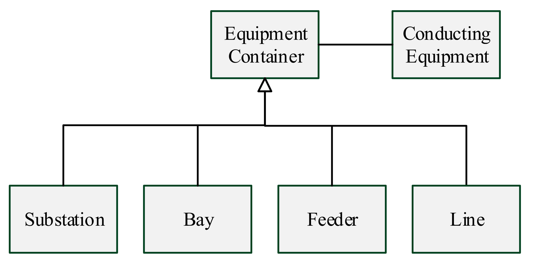
The feeder model, as specified in the IEC 61970 Part 301 CIM, is a static collection of conducting equipment that originates from the main distribution center and supplies one or more secondary distribution centers [
14], one or more branch-circuit distribution centers, or any combination of these two types of equipment. A feeder’s equipment can contain a substation or bay, as shown in
Figure 2 [
14]. In the distribution grid, however, all conducting equipment is considered a member of either a substation or a feeder. All substation equipment is housed. A feeder is generally outside a physical enclosure and consists of a collection or connected set of AC line segments, switches, transformers (which may or may not be considered a substation) [
26,
27], etc. Additionally, it can usually be sectionalized by closing certain devices and is protected by fuses.
3.3. Topology Model
The topology of the feeder refers to the connection relationship between the outgoing break, sectional switch, and the line segments of the feeder.
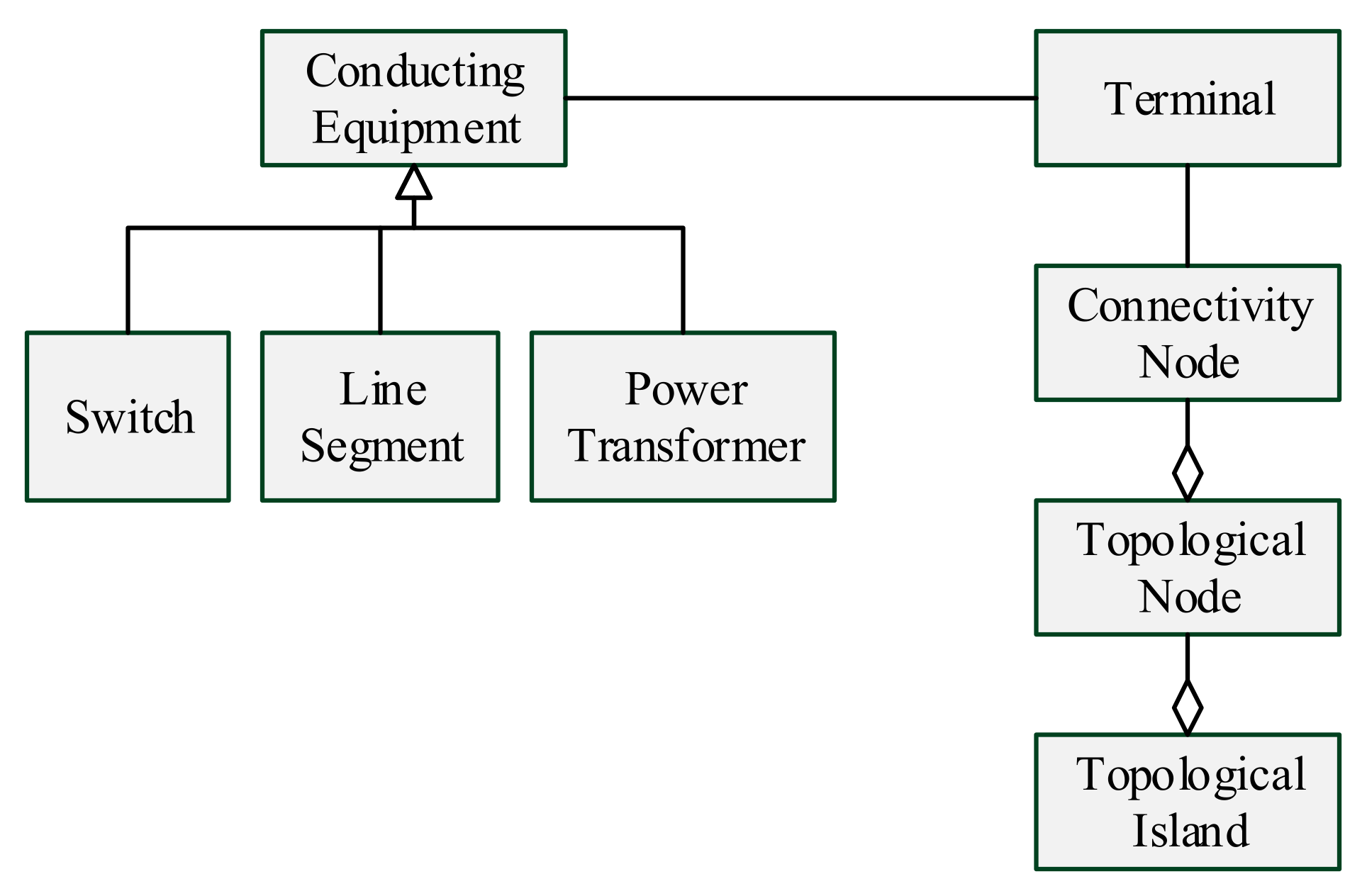
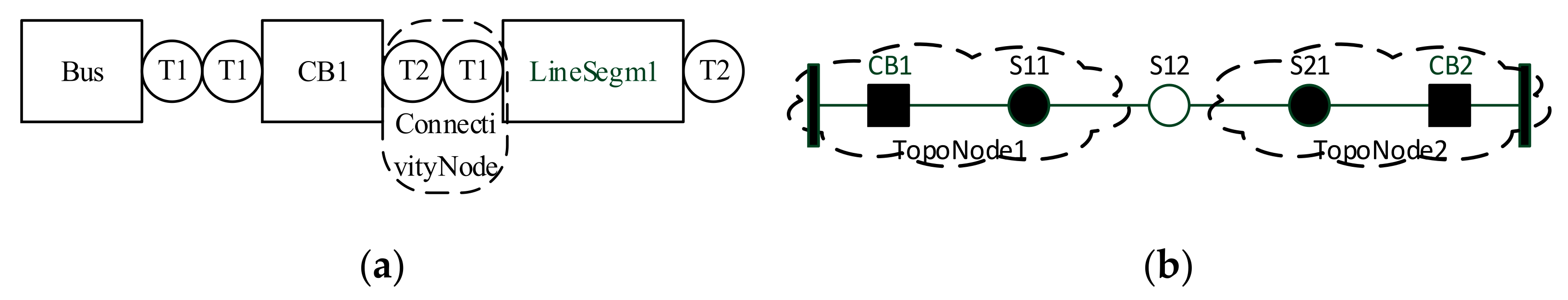
Figure 3 shows the topology class diagram that models the connectivity between different types of conducting equipment. IEC 61970 is divided into connectivity and topology models. The connectivity model is the physical definition of how the equipment is all connected together, and it is associated with the terminal and connectivity node classes, as shown in
Figure 4a. The connectivity model is a relatively static model, only related to the planning and design of the distribution grid and having nothing to do with the operation mode. The topology model, on the other hand, is the logical definition of how equipment is connected via closed switches using the topological node and topological island classes, as shown in
Figure 4b. The topology model is considered a dynamic model that can be modified through changes in the switch position and operation mode. In addition, the topology model is not identical when used for different applications. For example, during fault location and isolation, we are only concerned with the topology of a single feeder, but when the power supply is restored, it is necessary to consider the topology of all those feeders connected to the fault section. Therefore, the topology model is also related to its specific application, and we thus call this application topology.
4. Connectivity Model and Configuration
4.1. Connectivity Model
The feeder connectivity model describes the connection relationship between the distribution grid equipment along the feeder. To model connectivity, the terminal and connectivity node classes are all used. As defined in the CIM of IEC 61970, each conducting equipment has one, two, or more terminals, and each terminal belongs to one conducting equipment, and may be connected to a connectivity node, as shown in
Figure 4a. A connectivity node is a point where the conducting equipment’s terminals are all connected together with zero impedance. Distribution equipment can be divided into two categories: component equipment and station equipment. Component equipment consists of specific primary and secondary equipment, such as circuit breakers, load switches, disconnectors, current transformers, voltage transformers, etc. Station equipment, meanwhile, refers to the collection of a group of equipment that is used to complete the functions of the feeder line segmentation, power distribution, collection, etc., including the ring main unit, switching station, power distribution room, etc. To simplify the topology of the feeder, then, is the purpose of setting up the substation equipment. The topology of the internal station equipment needs to be described in detail, while for external station equipment, only a few terminals are mentioned. For example, the ring main unit is considered station equipment. For this piece of equipment, the detailed connection relationship of several switches needs to be described for the internal aspect, while for the external aspect, as it is a component of the feeder, only two terminals are required.
4.2. SCL Description for Connectivity Model
According to IEC 61850-6 [
28] and IEC 61850-90-6 [
29], SCL can be used to both describe and configure the connectivity model. Each IED needs only to configure the relevant connection relationship. The SCL defined in IEC 61850-6, meanwhile, can describe the connection relationship of the equipment along the feeder. In order to describe the feeder and its equipment, the feeder model shown in
Figure 2 is used. A feeder, like a substation, is an equipment container. However, the equipment in the substation belongs to the Substation class, and the equipment along the feeder belongs to the Feeder class.
The phase attribute must be in the connection model. In distribution networks, especially in LV ones, single-phase lines and two-phase lines are very common. The connection node may be a single-phase connection (A, B, C), two-phase connection (AB, BC, AC), or three-phase connection (ABC). Furthermore, it is necessary to extend the terminal in IEC 61850-6 to include the phases attribute. With the terminal phases attribute, the phase information of each conducting equipment can be expressed for multi-phase distribution networks. The data type of the phase is “Phase Enum”, and the data value may be “A”, “B”, “C”, “N”, “all”, “none”, “AB”, “BC”, or “CA”, while the default value is “all”. In this way, it can remain compatible with the original version.
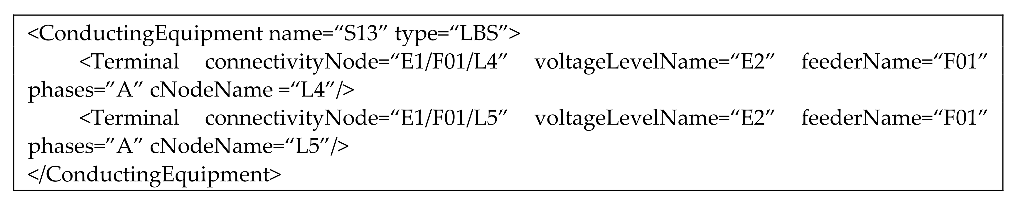
Taking the S11 load switch in
Figure 1b as an example, the description is as follows:
![Energies 14 04230 i001]()
In
Figure 1b, S13 is a single-phase switch.
![Energies 14 04230 i002]()
The following example describes the feeder in
Figure 1b.
![Energies 14 04230 i003]()
4.3. Logical Nodes for Connectivity Model
The logical node is the smallest part of the function that exchanges data. It is, therefore, more convenient to use logical nodes for information exchange between IEDs. Moreover, the logical node can also be expanded according to functional requirements. In DFA, IEDs need to be able to exchange the connection information of the distribution lines. For this information section, however, no necessary logical node exists to support the information exchange. Therefore, it is necessary to extend the logical nodes. The extension requirements of the logical nodes mainly include the following: (1) terminal information needs to be added for electrical equipment; and (2) connectivity node information description needs to be added.
4.3.1. Terminal
For conductive equipment, the description of terminal information should be added, including information on the circuit breaker (XCBR), circuit switch (XSWI), overhead line (ZLIN), cable (ZCAB), transformer (YPTR), as well as other logical nodes. Taking the circuit breaker logical node XCBR (in
Table 1) as an example:
Similarly, other logical nodes, including SXWI, ZLIN, ZCAB, and YPTR, should add the description of their terminals as XCBR.
Taking the switch S11 in
Figure 1b as an example, the attribute values of the logical node XCBR are as shown in
Table 2:
4.3.2. Connectivity Node
Connectivity nodes (as
Table 3) are the points where conducting equipment terminals are connected together with zero impedance. The connectivity node in a substation is generally only limited to one bay. For FA meanwhile, the connectivity node can be in the feeder. Its name attribute identifies the instance of the connectivity node instance within the bay; its path name is an absolute reference within the SCL file. For instance, if the connectivity node L1 is within feeder F1 of voltage level E1, then the pathname is “E1/F1/L1.”
When taking the leftmost connectivity node in
Figure 1b as an example, its data attributes are as shown in
Table 1.
5. Topology Model and Application
5.1. Topology Model
Topology is the logical definition of how equipment is connected via closed switches, and is independent of other electrical characteristics, such as impedance. To model topology, both the topological node and topological island classes in IEC 61970 are needed. A topological node, consisting of a group of connectivity nodes that are connected by the closed switches in the current network state, will change with the switch state. A Topological Island is an electrically connected subset of the network, which can change as the current network state changes. Only energized topological nodes form part of the Topological Island, meaning that a topological island is able to form a power supply area. A topological island will be located adjacently to another topological island through a tie switch. If a topological island has several tie switches that are all connected with other topological islands, there will be several power supply recovery paths.
5.2. Logical Node for Topology
For an IED, the topology analysis consists of synthesizing a topological node from the connectivity node connected through the closed switch. The number of connectivity nodes contained in each topological node needs to be transferred when exchanging topology information between adjacent IEDs. To calculate the topology of the whole feeder, the master IED is also needed. The master IED starts the whole feeder topology analysis and obtains the topology information through a successive polling of the adjacent IEDs.
For the exchange of topology information, the new logical nodes LTPN (as
Table 4) and FTPA (as
Table 5) must be added. The logical node LTPN starts the topology analysis and reports the topology results. When a switch position changes, the topology analysis (FTPA.Str = 1) is started, and FTPA.Str indicates the topology analysis state. The topology analysis results in the logical node, LTPN. Connectivity nodes at both terminals are then combined into one topological node through the closed switch, and the connectivity nodes at both terminals of the line segment are then merged into one topological node.
As shown in
Figure 3b, when the S12 switch is in its open state, two LTPN logical nodes are formed in the figure. The LTPN and FTPA logical nodes are as shown in
Table 6.
5.3. Topology Analysis of IED
For an IED, only some equipment needs to be monitored, and the method used for the topology analysis is relatively simple. The depth-first method can be used to generate topological nodes, with the following steps taken:
- (1)
The topology analysis starts, FTPA.Str = 1, with an IED start, or a switch state change.
- (2)
All the topological nodes should be cleared. The unprocessed flag of the topological node is set to 1.
- (3)
The depth-first method is used to traverse all the connectivity nodes.
If the connectivity node’s unprocessed flag is 1, a new topological node is enabled, and the connectivity node information is filled into it. The connectivity nodes connected by closed switch or line segments are combined into one topological node.
- (4)
Finally, the generated topology nodes array information should be put into FTPA. This marks the completion of the topology analysis.
5.4. Topology Analysis for the Feeder
In order to carry out the topology analysis of the whole feeder, or for multiple feeders, cooperation between several IEDs is needed. References [
18,
21] provide a successive polling method for the feeder topology analysis. The following steps are taken:
- (1)
The master IED sends the network topology query command to its adjacent IEDs.
- (2)
The IED receiving the query command replies with the information of the monitored switches and forwards the query command to its next level neighbor IEDs.
Repeat this step until the end of the feeder.
- (3)
The master IED obtains the feeder’s real-time topology according to all the returned topology information.
The exchanged information in this method includes connectivity and topology information. The connectivity information is exchanged with the terminal information of the device in
Section 4.3, while the topology analysis results can be exchanged through the topological node information discussed in
Section 5.2.
5.5. Case Analysis
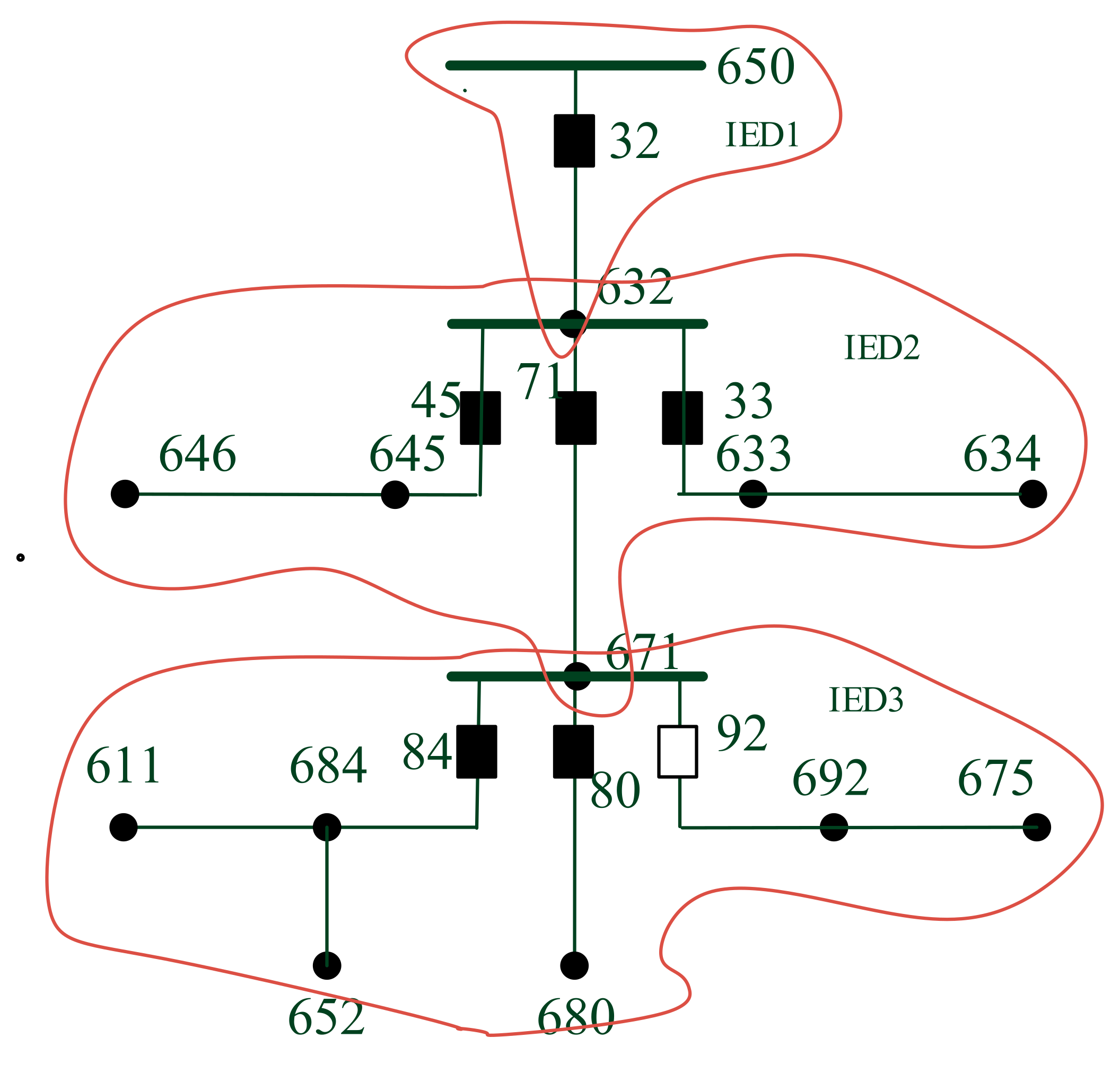
Based on the IEEE 13 node test feeder, the section switches and IEDs are arranged on the feeder as shown in
Figure 5.
As shown in
Figure 5, three IEDs are placed on the IEEE 13-node feeder, with each IED configured with a local topology. When analyzing the feeder topology, the three IEDs first analyze the local topology according to the algorithm in
Section 5.3, then IED1 is used as the main control IED, and the feeder topology is analyzed according to the algorithm in
Section 5.4. The information exchange between IED1, IED2, and IED3 is carried out according to the logical nodes in
Section 4.3 and
Section 5.2.
Firstly, a local topology analysis is carried out on both IED2 and IED3. IED1 is relatively simple, as following a local topology analysis, one topology node is formed. For IED2, the switches 45, 71, and 33 in are all closed, and so form one topology node. In IED3 meanwhile, switch 92 is open, which forms two topology nodes.
Next, IED1 initiates a level-by-level query, IED1, IED2, and IED3, and after this level-by-level query, it must be merged with the topology node. The wiring diagram shown in
Figure 4 finally forms two topology nodes.
So far, the topology analysis is completed and correct.
6. Conclusions
Topology contains important information regarding MV and LV DA and IoT. Feeder topology includes the connectivity model and operation topology model. IEC 61850 lacks the mechanism of feeder topology information exchange. To fill this gap, standard models were developed for topology based on the IEC 61850 standard’s information model. As an equipment set, the Feeder class defined in IEC 61970 needs to be extended and applied in IEC 61850, while the equipment connection information is described by the SCL of IEC 61850. The exchange between terminal devices can pass on the relevant terminal information and add a description of the connection node’s logical LCNN node. Finally, for the resulting topology analysis information exchange, it is necessary to add the topology analysis and topology logical node (FTPA) and the logical topological node (LTPN) in order to achieve an efficient information exchange. The IEEE 13-node model and three IEDs were used to verify the effectiveness of the proposed method.
Since the frameworks were developed according to a popular standard, it enables plug-and-play operation for smart grids. Furthermore, the requirement of topology information will change with different distributed applications. More and more distributed applications, such as feeder fault detection, distribution network reconfiguration, and edge computing, need different application topology information. For more complex application scenarios and more complex feeder structure, we also need to optimize the feeder topology information exchange mechanism.


