1. Introduction
Indonesia, located on the equator, is an archipelago country with 70% of its area surrounded by the ocean. Evaporation is very high, and such a condition is an advantage for forming thunder clouds. Therefore, Indonesia is one of the countries with the highest frequency of lightning strikes in the world [
1]. One of the districts in East Java, Gresik, has about 159 days of thunder per year. Although this is not too high, it is still a severe threat for Plant 1 of a petrochemical company in this area, especially the prilling tower and DCS building. Some unnecessary shutdowns have occurred due to indirect strikes of lightning.
Sometimes, the harmony of design between external lightning protection, internal lightning protection, and the grounding system is ignored. This can cause serious problems, such as the breakdown of equipment until the plant shuts down. These breakdowns and plant shutdowns have a huge economic impact on the production and revenue of the company.
Blackouts often occur after lightning strikes in the plant area. In one such instance, the operator had previously removed the surge protective device (SPD) from the protection system, following the instructions of the company’s consultant to deal with this phenomenon. Since this blackout phenomenon due to lightning strikes has been a repeated occurrence, a more comprehensive investigation is required to provide the most accurate recommendations and analysis.
The accuracy of this study depends on the grounding system modeling. Many researchers have remarked on electrical soil characteristics. This study also refers to Bhumkittipich’s [
2] use of resistance without inductance. This modeling is a proven method and is acknowledged in many studies. Also, it is understood that the accuracy will not be as good as soil characteristic modeling complete will inductance, but it is still acceptable for industrial applications.
Several studies on the effect of lightning strikes on transmission lines, tall structures, step-voltage phenomena, grid or mesh grounding systems, and substations have been done [
3,
4,
5,
6,
7,
8]. However, few studies comprehensively investigate the impact of lightning strikes that may cause failure in the low-voltage electrical system.
This study investigates and evaluates the lightning protection system of the prilling tower and DCS buildings on Plant 1, which is suspected of being the cause of shutdowns from lightning strikes. The prilling tower is the tallest building, and the DCS building contains instrumentation and control equipment that is highly sensitive to lightning disturbances [
9]. This study also comprehensively studied the external lightning protection system, internal lightning protection system, and grounding system.
2. Lightning and Its Protection System
2.1. Lightning
Lightning strikes are probabilistic natural phenomena that can cause damage to buildings, disturbing electronic equipment and even resulting in deaths [
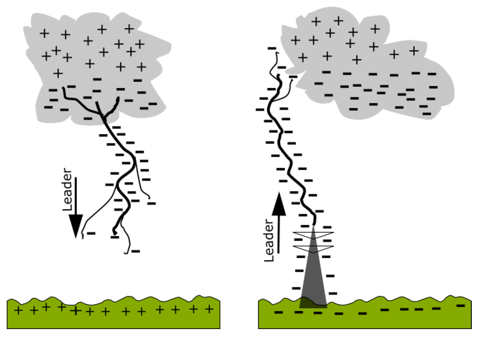
10]. According to IEEE Standard 998-1996, a lightning strike occurs in two steps, i.e., electron charging from cloud to ground due to gas ionization in the air, and then the return strike.
The ionization process results in an electric field between the cloud and ground. If the electric field is about 100 million volts, the downward leader discharge occurs in the form of a step leader. The formation of a high speed down leader results in an increased potential difference between the tip of the step leader and the ground, and then triggers the upward leader from the high-rise object on the ground. This process proceeds until both leaders meet at a point at a certain height [
11]. This mechanism is shown in the simplified model of
Figure 1.
2.2. Lightning Protection System
A lightning protection system (LPS) is an effort to overcome the potential hazard due to lightning strikes [
12]. There are two types of LPS: external LPS aimed at protecting objects from a direct strike, and internal LPS serving to protect objects from an indirect strike of lightning.
The design of LPS for a building area should be analyzed carefully to minimize the harmful effect of lightning; an LPS may not even be required at all. It is all closely related to the number of days of thunder per year for the area under study [
13]. As stated in IEC 61024-1-1, the required lightning protection level can be determined by using Equations (1)–(3) below [
14]:
where,
a = length of building roof (m)
b = width of building roof (m)
h = height of building roof (m)
Td = days of thunder per year
Ng = density of lightning strike to ground (strike/km2/year)
Nd = number of lightning strikes per year
Ae = area with Nd lightning strikes per year
2.3. Rolling Sphere Method
The rolling sphere method (RSM), as written in IEC 62303, employs an imaginary sphere of radius
R rolled on an object. The area where the sphere touches the surface of the building must be protected from lightning strikes. The value of
R can be calculated using Equation (4) [
15]. The value of
R can then be used to determine the required lightning protection level (LPL), as shown in
Table 1.
where,
R = Rolling sphere radius
I = Estimated magnitude of lightning current
2.4. Protection Angle Method
Another protection method recommended by IEC 62305 is the protection angle (PA) method. However, certain limitations cause this method to be not applicable to plants with towers. Equation (5) by Hasse and Wiesinger is the equation that can be used to determine the lightning protection zone for the PA method.
where:
= protection angle
h = building height (m)
r = strike distance (m)
2.5. Grounding and Ground Potential Rise
The Grounding system aims to flow lightning currents to the ground. There are three types of grounding, namely power or electrical, lightning, and instrumentation groundings [
16].
Ground Potential Rise (GPR), according to IEEE 367, is a phenomenon of potential rise due to the current flowing in a ground rod impedance [
17]. For safety reasons, the GPR should not be higher than the safety limit and must not generate touch and step voltages. According to a study done by Jinliang He, the maximum GPR on a grounding system is about 5 kV [
18].
In this paper, ground conductor resistance was used as a model and refers to a standard that only uses ground resistance for grounding design calculations, such as IEEE Std. 80, IEC 62305, etc. This method is sufficient, proven, and will not neglect the minimum requirement of a good lightning protection system design. Nevertheless, in the future, if accuracy is the main issue, the inductance and capacitance of the grounding rod and grounding cable can be included in the simulation.
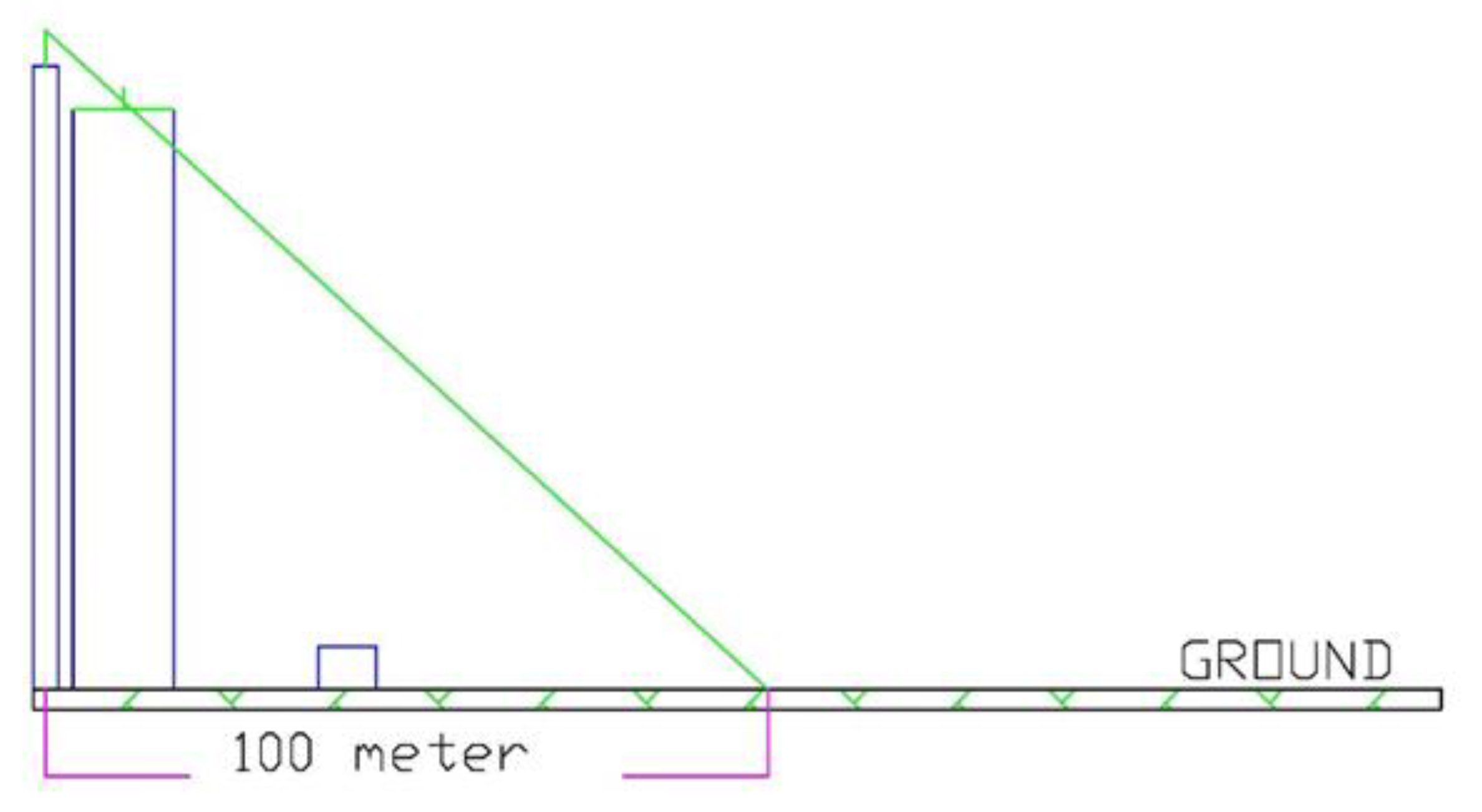
A lightning current flowing to the ground through an electrode affects the other electrode at a certain distance. The lightning current is distributed radially on the ground, as shown in
Figure 2 [
19]. If lightning strikes the ground, the lightning current is distributed radially. Consequently, an equipotential area is formed in the ground, as shown by the blue line in the figure. These potential differences cause the current to flow from higher to lower potentials at a certain distance, and then resulting in a potential ground rise in other grounding rods. The ground resistance between ground electrodes (
Rh) can be calculated using Equation (6):
where:
Rh = resistance between two ground rods with distance r2 (Ω)
ρ = ground resistivity (Ωm)
r1 = ground rod depth (m)
r2 = electrode distance (m)
Ground conductor and down conductor resistances (
Rd) are determined using Equation (7):
3. Data and Model
3.1. Prilling Tower Data
The prilling tower of the plant under study is 80 m and 14 m in height and width, respectively. The existing external LPS was installed in another tower with a height of 86 m. Its distance is about 2 m away from the prilling tower. This LPS is a non-conventional Dyna sphere-type, installed 5 m from the top of the tower, with a maximum protection radius of 100 m.
3.2. Grounding DCS Building
The data for the grounding system of the DCS building-based on-site survey are shown in
Table 2.
The measurements of ground resistances using the driven rod method are depicted in
Table 3.
3.3. Grounding System Model
In this study, the grounding system was modeled using ATP/EMTP.
Figure 3 depicts the existing and modified models of the grounding system, where the grounding rods are separated from each other. In order to evaluate the effect of the equipotential grounding system,
Figure 3a was modified by connecting all ground rods and representing equivalent resistances in the model as shown in
Figure 3b.
4. Analysis Lightning Protection Systems
In general, two problems were discussed in this investigation, namely the lightning protection of the prilling tower and DCS building of Plant 1 of a petrochemical industry in Gresik, Indonesia.
4.1. Evaluation of Lightning Protection Level
The density of lightning strikes to the ground was calculated using Equation (1) through Equation (3), and it was found that the density of lightning strikes to the ground (Ng) is about 23.76 per km2 per year. Moreover, the frequency of direct lightning strikes (Nd) is about 4.62 strikes a year. Based on the calculation results and economic considerations, it would be reasonable to choose a lightning protection level (LPL) of 4. LPL 4 was then used to analyze the protection system by using the rolling sphere method.
4.2. Evaluation of Existing LPS Using Rolling Sphere Method
LPL 4 was chosen to analyze the protection system using RSM. This means that the LPS should be able to capture a minimum lightning current of 16 kA. Using Equation (4), the radius of the rolling sphere is 60.63 m (giving a rounded figure of 60 m).
Figure 4 shows the RSM model of the existing protection zones of the prilling tower and DCS building LPSs. It clearly shows that the installed external LPS does not meet IEC 1024-1-1 and IEC 62305 standards.
We propose to improve the existing external LPS by adding a 3 m high air termination installed at the center of the prilling tower roof, and a mesh conductor around the roof as high as 1.66 m, as shown in
Figure 5. In this way, the prilling tower would be protected adequately, as shown in
Figure 6.
4.3. Analysis of Protection Angle Method
Based on the existing LPS, it is known that the height of the existing air termination is 91 m, and the protection radius area is about 100 m. Therefore, the protection angle can be calculated as follows:
This means that if the protection system works at a maximum protection radius, the protection angle of air termination is 47.7° as shown in
Figure 7.
The model also shows the condition of the modified LPS of the prilling tower. By knowing its protection angle and by using Equations (4) and (5), it was found that the striking distance is about 249.5 m, with the maximum lightning current that can be captured measuring about 236.8 kA.
4.4. Analysis of Existing Grounding System
The simulation was done using the model shown in
Figure 3, and the lightning currents used were 10 kA, 20 kA, and 30 kA. The lightning model was 1.2 μs/50 μs. The result for the GPR of the separated grounding system, or the system without any connection between grounding rods, is depicted in
Table 4.
From
Table 1, it is clearly shown that if the lightning current is more than 20 kA, then the GPR at some of the points measured do not align with the maximum allowed GPR of 5 kV. On the other hand, the transient overvoltage at the transformer still aligns with the maximum of 30 kV for a 6 kV system [
19].
Connecting all of the grounding rods in the system aims to make the grounding system have the same potential throughout (equipotential). The simulation results of the equipotential system can be seen in
Table 5. The new ground rod resistance chosen in the simulation was 0.75 Ω.
As seen in
Table 5, the ground potential rise for each lightning current is relatively similar. The similar ground potential of the system means that the occurrence of a ground loop during a lightning strike can be avoided. Therefore, there is no current flow between the grounding rods. Moreover, the GPR at all measured points was relatively small compared to the system without an equipotential grounding rod. Some problems might be overcome with this system; however, the system still requires improvement because at a lightning current of 30 kA, the GPR is still more than 5 kV.
In order to improve the grounding system so that the GPR is acceptable, it is proposed to install an additional surge protective device (SPD) at some point on the equipotential grounding system. According to Joe Zulio, SPDs can minimize the effect of lightning strikes [
20]. An SPD acts as low-voltage lightning arresters and is installed in the incoming electrical system. Its grounding is connected as short as to the equipment grounding. The configuration of the installed SPD can be seen in
Figure 8.
The simulation results of GPR investigated at some points of the equipotential grounding system with SPD can be seen in
Table 6. The results show that this combination can reduce the magnitude of GPR significantly; GPR on the transformer was under 1 kV for all lightning currents simulated.
Moreover, the GPR at the grounding system investigated was lower than 100 V; therefore, the combination of an equipotential grounding system and a low-voltage SPD is recommended for the grounding system of the DCS building.
5. Conclusions
The lightning protection and grounding systems of the prilling tower and DCS building of Plant I of a petrochemical company were evaluated and investigated. Based on the investigation, some essential points can be concluded and some improvements can be suggested as follows:
The required protection level of the lightning protection system was determined to be 4, based on IEC 62305, which would capture the minimum lightning current of 16 kA.
Based on the rolling sphere method, the existing LPS installed at the tower near the prilling tower cannot protect it. It is suggested to install an LPS at the top of the prilling tower with a 3 m high conventional air termination and a 1.66 m high mesh conductor.
Potential Ground Rise (GPR) on the existing grounding system of the DCS building was more than 5 kV at a lightning current of 20 kA or higher. It did not meet the standard. Improvements have been suggested by connecting all the grounding rods. In this way, they would become a one-point equipotential grounding and low-voltage surge protection system (SPD). Based on the simulation done, the suggested improvement could reduce the GPR to be under 100 volts at some points investigated.
From the results above, the external lightning protection, internal lightning protection, and grounding system need to be connected to make a sound lightning protection system. In the future, the inductance and capacitance of ground rods and ground conductors could be considered to improve GPR prediction.
Author Contributions
Conceptualization, D.F.; Data curation, I.S.H.; Investigation, A.B.K.; Validation, R.B.P.; Writing—original draft, I.M.Y.N.; Writing—review & editing, D.F. and D.A.A. All authors have read and agreed to the published version of the manuscript.
Funding
This research received no external funding.
Institutional Review Board Statement
Not applicable.
Informed Consent Statement
Not applicable.
Acknowledgments
The author would like to thanks the petrochemical company in Gresik Indonesia for all data provided and allowed the authors to do some measurement on site and supports provided by Institut Teknologi Sepuluh Nopember on research facilities.
Conflicts of Interest
The authors declare no conflict of interest.
References
- Supartono, E.; Haryono, T.; Suharyanto. Application of Cone Protection and Rolling Sphere Method in External Lightning Protection Analysis on 214 Radar Tower. Int. J. Adv. Eng. Technol. 2015, 8, 475–481. [Google Scholar]
- Bhumkittipich, K.; Topradith, B.; Suwanasrim, T. Analysis of Lightning Phenomena for Underground Petroleum Pipeline System. Energy Procedia 2013, 34, 148–158. [Google Scholar] [CrossRef] [Green Version]
- Thasananutariya, T.; Spuntupong, K.; Chatratana, S. Design of Grounding System for GIS Indoor Substation. In Proceedings of the 2004 IEEE Region 10 Conference TENCON, Chiang Mai, Thailand, 21−24 November 2004; pp. 413–416. [Google Scholar]
- Parise, G.; Gatta, F.; Lauria, S. Common Grounding System. In Proceedings of the IEEE Systems Technical Conference on Industrial and Commercial Power, Saragota Spring, NY, USA, 8−12 May 2005; pp. 184–190. [Google Scholar]
- Khodr, H.M.; Salloum, G.A.; Miranda, V. Grounding System Design in Electrical Substation: An Optimization Approach. In Proceedings of the IEEE/PES Transmission & Distribution Conference and Exposition Latin America, Caracas, Venezuela, 15−18 August 2006. [Google Scholar]
- Neamt, L.; Balan, H.; Chiver, O.; Hotea, A. Considerations about Substation Grounding System Design. In Proceedings of the 8th International Conference on Modern Power Systems (MPS), Cluj, Romania, 21−23 May 2019. [Google Scholar]
- Reffin, M.S.; Nor, N.M.; Ahmad, N.N.; Abdullah, S. Performance of Practical Grounding Systems under High Impulse Conditions. Energies 2018, 11, 3187. [Google Scholar] [CrossRef] [Green Version]
- Mohamad, M.P.A.; Yahaya, M.P.; Hudi, N.S. Revised Tower Earthing Design in High-Voltage Transmission Network for High-Frequency Lightning Condition; Journal of Physics: Conference Series; IOP Publishing: Bristol, UK, 2021; Volume 1878. [Google Scholar]
- Hasse, P. Overvoltage Protection of Low Voltage System, 2nd ed.; The Institution of Engineering and Technology: London, UK, 2008. [Google Scholar]
- Cooray, V. Lightning Protection; The Institution of Engineering and Technology: London, UK, 2010. [Google Scholar]
- DEHN. Lightning Protection Guide, 3rd ed.; DEHN + SÖHNE: Neumarkt, Germany, 2014. [Google Scholar]
- IEC 62305. International Standard on Protection against Lightning; International Electrotechnical Commission [IEC]: Jenewa, Switzerland, 2006. [Google Scholar]
- Pujiantara, R.F. Analysis of Lightning Protection System of PT Medco E & P Lematang. In Final Project; Electrical Engineering Dept. ITS: Surabaya, Indonesia, 2015. (In Indonesian) [Google Scholar]
- IEC 61024. Protection against Lightning Electromagnetic; International Electrotechnical Commission [IEC]: Jenewa, Switzerland, 2006. [Google Scholar]
- Ait-Amar, S.; Berger, G. A Modified Version of the Rolling Sphere Method. IEEE Trans. Dielectr. Electr. Insul. 2009, 16, 718–725. [Google Scholar] [CrossRef]
- Vijayaraghavan, G.; Brown, M.; Barnes, M. Practical Grounding, Bonding, Shielding and Surge Protection; IDC Technologies: Oxford, UK, 2004. [Google Scholar]
- Sekioka, S.; Aiba, K.; Okabe, S. Lightning Overvoltages on Low Voltage Circuit Caused by Ground Potential Rise. In Proceedings of the International Confrence on Power Systems Transient (IPST’07), Lyon, France, 4−7 June 2007. [Google Scholar]
- He, J.; Zhang, B.; Zeng, R. Maximum Limit of Allowable Ground Potential Rise of Substation Grounding System. IEEE Trans. Ind. Appl. 2015, 51, 5010–5016. [Google Scholar] [CrossRef]
- IEC 60664-1. Insulation Coordination for Equipment within Low-Voltage; International Electrotechnical Commission [IEC]: Jenewa, Switzerland, 2007. [Google Scholar]
- Zullo, J. Proper Grounding of Instrument and Control Systems in Hazardous Locations. In Proceedings of the Explosion Protection and Hazardous Locations Conference, Kyoto, Japan, 2 June 2009; IDC Technologies: San Jose, CA, USA, 2009; pp. 1–12. [Google Scholar]
| Publisher’s Note: MDPI stays neutral with regard to jurisdictional claims in published maps and institutional affiliations. |
© 2021 by the authors. Licensee MDPI, Basel, Switzerland. This article is an open access article distributed under the terms and conditions of the Creative Commons Attribution (CC BY) license (https://creativecommons.org/licenses/by/4.0/).


 ,
, 


