Abstract
In this work, the integration of a grid-scale ternary-Pumped Thermal Electricity Storage (t-PTES) with a nuclear power generation to enhance operation flexibility is assessed using physics-based models and digital real time simulation. A part of the electricity from the nuclear power generation is delivered to the grid, and the balance is used to power a heat pump that can be augmented by an auxiliary resistive load element to increase the charging rate of the thermal storage. This increases the thermal potential between hot and cold thermal stores (usually solid materials or molten salts inside large storage tanks). The thermal energy is transformed back into electricity by reversing the heat pump cycle. Different transient scenarios including startup, shutdown, and power change for grid-connected operation are simulated to determine the behavior of the hybrid nuclear-t-PTES system operating under variable loads that constitute a departure from conventional, baseload nuclear plant operation schemes. Ternary refers to the three modes operation: (i) heat pump (including heating coil), (ii) heat engine, and (iii) simultaneous operation of heat pump (including heating coil) and heat engine during changeover from pumping to generation or vice-versa. The controllability of t-PTES in the short timescales as a dynamic load is used to demonstrate operational flexibility of hybrid nuclear plants for flexible operation through advanced load management. The integration of t-PTES into nuclear power systems enhances the system flexibility and is an enabler for high penetration of renewable energy resources.
1. Introduction
Nuclear power generation is a mature, reliable, and clean technology with the highest energy density, that has been the backbone of the U.S. power generation portfolio for several decades. Traditionally, the nuclear generation fleet have operated as fully committed baseload units and the nuclear reactor designs have not experienced significant and disruptive innovation during the last decades [1]. One of the main limitations of nuclear reactors is the lack of flexibility in operation due to thermal cycling constraints. The highly variable external demands would require a departure from the conventional, base-load nuclear plant operation scheme and off-design operation. This transient operation impacts plant performance, components lifetime, and requires robust design and maintenance procedures. Efforts to address this limitation include the development of small modular reactors (SMRs) and microreactors; while being lower power rated, these can achieve some level of flexible operation [2,3,4]. In general, the next generation of nuclear reactors must be adaptive to maintain long-term competitiveness in a continually evolving power generation market characterized by a growing penetration of variable renewable energy sources. Another alternative to improve flexible operation is related with the integration of nuclear power generation with renewable energy generation, fossil-fuel generation systems and energy storage technologies [4,5,6].
To better understand the real behavior of integrated nuclear with other thermal systems like the ternary-Pumped Thermal Electricity Storage (t-PTES), it is imperative to perform transient analyses that include co-simulation of thermal and electrical characteristics in a high-fidelity computing environment. Understanding and quantifying the flexibility of grid connected t-PTES systems under different transient scenarios is fundamental for assessing new system configurations, developing optimal operation modes, and reducing maintenance costs.
This proposed project represents a high-impact contribution toward realizing an advanced reactor technology that can (a) attain a level of maturity in a time frame competitive with other thermal power generation technologies, and (b) maintain competitive operational performance in a rapidly evolving power generation network. The deployment of previous generations of reactor technology in the United States has suffered from the significant costs to mature a technology to the point that high levels of operational efficiency are achieved. The incorporation of advanced data analytic systems within next generation reactor technologies presents the potential to utilize operational data to dynamically, and rapidly, optimize the operation of the new technology in supplying intended demand(s) and adapt more rapidly to changes in demands from external consumers and availability of other generation sources.
2. Conceptual Overview
2.1. Enabling Flexibility from Nuclear
Standard operation of the nuclear power plant (NPP) is mandated by regulations based on strict safety guidelines. NPPs in the United States constitute the baseload generation due to economic reasons (lowest variable cost) and are not relied upon for up- and down-regulation [7,8,9]. High penetration of renewables is posing challenges for operation of conventional NPPs in a grid integrated with fast varying renewables and uncertainty due to limited accuracy in forecasting. The flexible operation of NPPs is popular in some countries such as Germany, France, Belgium, etc., thereby proving the capability of the nuclear technology to be quite flexible [7,10,11]. Flexibility for conventional NPPs without cycling can only be achieved through auxiliary power installations that can be tightly integrated with NPPs, provide adequate response for flexibility, and can allow coordinated control enabling the flexibility. We present one such systematic integration and thermal technology to achieve the NPP flexibility.
2.2. Ternary-Pumped Thermal Electricity Storage (t-PTES)
A ternary-Pumped Thermal Electricity Storage (t-PTES) system integrates a heat pump, a thermal energy storage tank system, and a heat engine with a grid-connected nuclear power plant, as can be seen in Figure 1. The t-PTES system is powered by a nuclear power plant running at nominal power and capable of flexible operation to follow the load requirements though fast- and low-response operation modes accomplished by the integration of the heat pump, the heat engine, and a direct electricity to thermal conversion device. The transition among operation modes is performed by a Nuclear Flexibility Enabler (NFE), a control-based interface that senses the load variations in sub-seconds and take decisions to divert instantaneous power excess or extract additional power from integrated components to satisfy the instantaneous electricity demand.
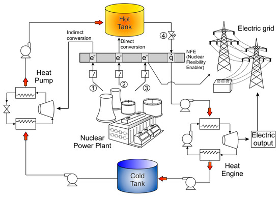
Figure 1.
Diagram of the ternary-Pumped Thermal Electricity Storage (t-PTES) system.
The three fundamental operational modes are (1) nuclear to heat pump to thermal storage; (2) nuclear to storage (direct conversion), and (3) storage to heat engine to grid. Ternary refers to the three modes operation: (i) heat pump (including heating coil), (ii) heat engine, and (iii) simultaneous operation of the heat pump (including the heating coil) and the heat engine during changeover from pumping to generation or vice-versa. Other important operational modes include the simultaneous operation of two or more integrated subsystems as can be appreciated in Figure 2. In all cases, the nuclear power plant operates at nominal power and the power flexibility is handled by the integrated subsystem managed by the NFE. Different operational modes can satisfy a variety of load requirements at different response times, from a daily load demand increase/decrease, changes in supply due to the grid-connected renewable based power generation, to fast response in power supply/curtailment due to a failure of an external grid-connected system.
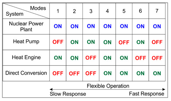
Figure 2.
Operational configurations for the t-PTES system.
The integration of Thermal Energy Storage (TES) technologies including Pumped Heat Electricity Storage (PHES) and a direct electricity to thermal conversion device into conventional NPPs enhances the system reliability and dispatchability as illustrated in Figure 3, enabling the path for an effective integration of renewable energy sources into the electric grid. PHES is a commercially proven technology that uses electricity to power a heat pump, which increases the thermal potential between hot and cold thermal stores (usually solid materials or molten salts inside large storage tanks). The thermal energy is transformed back into electricity using a heat engine (Rankine or Brayton cycle). In this work we have proposed a different set of turbomachines for the heat pump and the heat engine and it is worth noting that other approaches for PHES consider a single device to perform the heat pump and heat engine functions by reversion of the flow direction, but in this case reciprocating devices are required, and also additional time is needed to switch between charging and discharging functions.
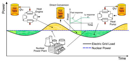
Figure 3.
Pictorial depiction of t-PTES operation to provide flexibility to nuclear power generation.
3. Modeling and Real Time Simulation
3.1. Dynamic Modeling
3.1.1. Ternary-Pumped Thermal Energy Storage (t-PTES)
The excess power from the nuclear power plant can be diverted and stored using the fast-response direct energy conversion through a submerged resistance in the hot tank and an indirect slow-response energy conversion through a heat pump. The change in power consumption, () as a function of the change shaft speed () for a Variable-Speed Heat Pump is expressed through the following second-order transfer function:
The values for the coefficients , , , and can be estimated using multiple polynomial regression of power vs. shaft speed curves for different heat source and heat sink temperatures [12]. The electrical power can be determined from the immediately previous power consumption () as follows:
The heat generated by the heat pump is a function of the Coefficient of performance and can be calculated from:
The is a function of the heat source (cold tank) and the heat sink (hot tank) temperatures ( and , respectively). The maximum achievable of a heat pump is described by the Carnot . The real can be calculated using a quality factor to scale down the Carnot . The for a real heat pump is calculated using a quadratic regression [13] and a scaled-down factor for the Carnot COP as follows:
where and the scaling factor = 0.317.
The thermal model for the hot tank is presented in Figure 4, and the corresponding energy balance for this component is described by Equation (5).
where = is the mass of Therminol VP-1 in the tank, (W) is the heat from the heat pump entering the tank, and (W) is the energy extracted from the tank. The heat loss is defined as , where is the overall heat transfer coefficient and is the area of the tank. The electrical work (direct conversion) is . Design parameters for the hot tank are presented in Table 1.
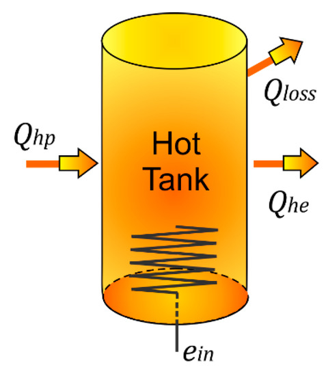
Figure 4.
Thermal model for the hot tank.

Table 1.
Design parameters for the hot tank.
In this work, is assumed to be approximately the temperature of the hot tank, i.e., . The initial temperature in the tank is and the maximum possible temperature in the tank is set to 700 K. The corresponding initial and maximum energy in the tank can be determined as and , respectively. The transfer function based on the energy balance of (5) is presented in Figure 5. A state-space model of the hot tank is shown in Appendix A.
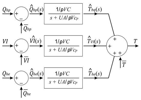
Figure 5.
Transfer functions for the hot tank.
The efficiency of the heat engine is defined as the ratio between the power output and the energy input:
The heat input and power output in kW for a Rankine cycle are determined from the following expressions [14] that are obtained from:
where, is defined and the equivalent efficiency that accounts for compression and expansion irreversibilities in the turbine and the pump of the Rankine cycle and is calculated from:
and are isentropic efficiencies for the turbine and the pump, respectively, while is the pump to turbine power ratio for the cycle. In this study the values for these parameters are , and , which correspond to characteristic parameters for real Rankine cycles.
The parameter is a ratio between effective conductance for heat input and heat dissipation heat exchangers that accounts for the thermal conductance and fluid characteristics including the specific heat capacity of water () and the mass flow rate () of water in the Rankine cycle.
3.1.2. Electric Grid
The electric grid is modeled in a Digital Real Time Simulation (DRTS) platform. The model consists of bulk generation and loads at transmission level. The simulations are performed on a modified 12-bus system, see Figure 6, consisting of three synchronous generators with thermal plant governors and five load buses [15]. A slack bus generator representing a strong grid (ideal source) is present at bus-9. For our analysis, the grid model is modified by integration of 40 DFIG-based wind turbines of 2.3 MW each at bus-4, and the generator at bus-12 is chosen as the representative 500 MW nuclear power plant (NPP) with a standard TGOV5 governor for simulations and integration of the t-PTES system [16,17].
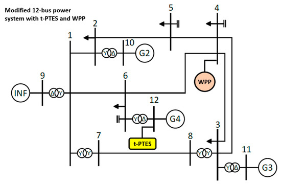
Figure 6.
One line diagram of the modified 12-bus power system. The 12-bus system in [15] is modified by integration of the 92 MW Wind Power Plant (WPP) and ternary-Pumped Thermal Energy Storage (t-PTES). The system is modeled in digital real-time simulation.
3.2. Controls
The controls for NFE are modeled as rule-based decisions using the fast operation of the heating coil to convert electrical energy to thermal energy when excess generation is present in the system. This fast control is first to operate the heating coil (60 MWe) in a sub-second timescale. The heat pump (45 MWe) is cut-in to additionally offset remaining excess generation or replace heating coil heat transfer after 600 s, as shown in Table 2. This is done to have additional up- and down-regulation margins as required by the grid state. The seamless changeover of heating coil and heat pump operation is demonstrated in the digital real-time simulations. The dynamic response of the heating coil is sub-second and heat pump response is about 30 s (0–100% output). The heat pump response is controlled by rate-limited ramping of the induction motor (IM) using VFD with V-f scalar control, where the speed controller is realized using a PI-controller, limiters, and saturation blocks. Since voltage is directly proportional to speed in V-f control, the voltage is built up slowly. This is done to avoid any oscillations of IM with the power network. Moreover, in the rule-based control logic, when the heat pump is ramping up, the heating coil is used to maintain the total electrical power consumed as a load through fast corrections, i.e., is maintained constant in real-time during the changeover. The heat engine has a smaller capacity (20 MWe) compared to the heat engine and heating coil. The heat engine is cut-in to extract energy from the hot tank and convert it to electricity. This electricity is put back on the grid and can be incorporated in the nuclear generation scheduling without a large deviation of nuclear power plant (NPP) baseload operation. The ability to have HP and HE operate independently, and simultaneously during changeover (transient modes) from net load to net generation, is the central idea of our concept. The capacities of 60 MWe for heating coil, 45 MWe for HP, and 20 MWe for HE were chosen with the rationale that t-PTES must be able to provide a regulation of up to 20% of the NPP capacity (approximately), which equates to a total of 105 MWe (45 + 60 MWe) for the HP and the heating coil. Heating coil cut-in/cut-out can result in a fast step response, and ranges to about 12% of NPP capacity, which is within the acceptable range of 15–20%. It is important to mention that for load-following operation of a PWR NPP, typically 15–20% of capacity has proven to be acceptable limits in the literature; we base our rationale on this. On the other hand, HE operation is more to help balance the state-of-charge (SOC) of the hot tank (thermal storage) where the heat from the hot tank can be used to generate electricity from the HE, that can be adjusted in NPP generation schedules with a maximum of (20 MWe/500 MWe × 100%) 4% regulation, without a large impact on NPP output. Although we do not aim to provide long-term or day-ahead generation scheduling in this paper and focus on dynamic aspects only, the use-cases for an electric grid with high renewable penetration will allow such a regulation to maintain hot tank SOC for up- and down-regulation. For example, in case of high penetration of solar PV the heat tank can be charged fully during the day, and the HE can be used during the night time for maintaining SOC for the next day. HP electrical power means the induction motor rating driving the compressor as a load in the heat pump. The compressor size is 40 MW, which is typical in large size LNG plants and can consist of multiple units (e.g., 5–10 MW each) and warrants a techno-economic analysis. We use aggregated large capacity to demonstrate the operational aspects for the proposed t-PTES concept in this paper. Techno-economic analysis can be a future research direction and not covered here. The control objective is to minimize the power deviation of NPP from the schedule.
Table 2.
Control rules and constraints for t-PTES.
3.2.1. Baseline Nuclear Power Plant Operation in Blue Sky Scenario
The baseload schedule of NPP without any auxiliary load is considered as the baseline for this paper during a blue-sky scenario. During the blue-sky scenario, the variability in load demand and renewable generation is considered. The up- and down-regulation of the NPP is coordinated by the NFE controls, thereby covering nominal variations through t-PTES without the need to change NPP power output. In certain situations, the NPP may be required to perform a load-following operation beyond the regulation capacity of the NFE. This is an extreme case where NPP output must be varied in conjunction with t-PTES. Such scenarios can be mitigated at plant level through a larger capacity t-PTES design (note: We consider a representative PWR design in the legacy NPP in this paper. We show through simulations, the effectiveness of t-PTES based on a certain capacity design targeting 15–20% of NPP regulation. We are not considering any comparison to new modular NPP designs. Although, the scope of our work only includes legacy PWR-based technology as a representative NPP and we have not done a comparative assessment with new generation modular NPPs, our understanding is that modular technology may provide more efficient and economical pathways to achieve flexibility through the next generation NPPs).
3.2.2. Flexibility during Blue Sky and Grey Sky Scenarios
The flexibility can be quantified for blue-sky and grey-sky scenarios by computing a flexibility metric considering power, energy, and ramping capability provided by the NFE (measured in kW, kWh, and kW/s, respectively). The performance can be quantified as improvement in frequency and power oscillations with and without the NFE. We show selective simulation results in this work for demonstrating the effectiveness of t-PTES for providing flexibility to the NPP.
3.2.3. Emergency Operation during Black Sky Scenario
Nuclear power plants can provide power during adverse situations such as natural disasters such as winter/snow storms, hurricanes, etc. The natural events can impact other grid assets including renewable generation, load sites, and power transmission/delivery infrastructure. The load demand can reduce drastically during black-sky scenarios and the NFE presented here offers a viable support option for maintaining stable operation of the NPP at partial loading for several hours without a complete shutdown. This allows the NPP to provide additional net power for critical loads once power transmission and delivery paths are restored.
4. Electrical-Thermal Co-Simulation
The NPP t-PTES system consists of several multi-physical elements ranging across electrical, thermal, and mechanical elements. The subsystems are integrated in a digital real-time environment using physics-based and linearized representation of thermal subsystems. The heat pump and heat engine are represented using transfer functions, the hot tank (thermal) is represented using state-space model (Appendix A) and the electrical grid and machines are modeled in detailed using electromagnetic transient (EMT) component models.
4.1. Integrated Electrical-Thermal System
The integrated system with NFE controls and t-PTES subsystems are shown in Figure 7 below. The three main subsystems of the t-TPES are: (i) heating coil, (ii) heat pump, and (iii) heat engine. The heating coil is modeled as a resistive load with 98.5% efficiency [18]. The heat pump is modeled using a variable frequency drive (VFD), and V/f control is used for simple speed control of the induction motor [19,20,21,22,23]. A feedforward control is adopted using the characterized curve for the power-speed curve for the VFD-based heat pump. The thermal model of the compressor, absorption chiller, and evaporator is modeled using a transfer function and equation-based modeling is used for the temperature-dependent coefficient of performance (COP) to obtain heat energy input to the hot tank.
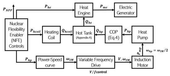
Figure 7.
Integrated electrical and thermal coupling variables for various subsystems of the t-PTES.
4.2. Case-Study I: 60 MW Step load Reduction at Bus-6
This case study shows fast response of the heating coil for improved transient response of the NPP generator with reduced frequency and power oscillations as shown in Figure 8. The heat transferred from the heating coil to the hot tank, energy (in KWh) and temperature (in degree K) of the heat tank are shown in Figure 9. Plots of power (y-axis, MW) versus rotational speed (x-axis, rad/s) for the baseline case with no NFE control (black curves) and with NFE controls (red curve) are shown in Figure 10.
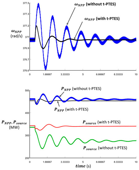
Figure 8.
Time-domain response of the NPP generator and source for the 60 MW step load drop at bus-6. It can be noted that frequency (top plots, rad/s) and power (bottom plots, MW) oscillations for both the NPP generator and source (ideal source representing bulk grid interconnection to the 12-bus 3 area power system) are reduced with the use of the heating coil (approx. 60 MW) which provides a sub-second response. (x-axis: time in seconds). In the top plots, the blue curve is NPP (G4) frequency (without t-PTES), and the black curve is NPP (G4) frequency (with t-PTES). In the bottom plots, blue and red curves: NPP (G4) power and source power (without t-PTES), and black and red curves: NPP (G4) power and source power (with t-PTES).
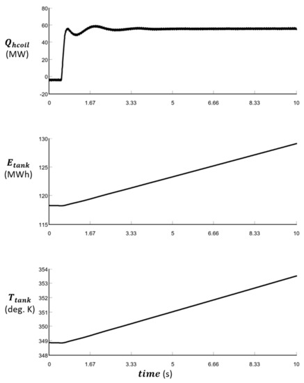
Figure 9.
Heat energy from the coil (in kW) produced by the heating coil (top); energy in the hot tank (kWh) produced by the heating coil (middle); and temperature increase (in degree K) of the hot tank increases with addition of heat from the coil (bottom).
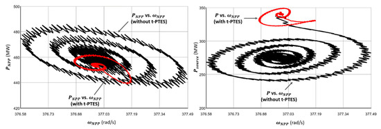
Figure 10.
Plots of power (y-axis, MW) versus rotational speed (x-axis, rad/s) for the baseline case with no NFE control (black curves) and with NFE controls (red curve). It may be noted that deviations are much smaller with NFE controls for both the NPP generator (left) and source (right).
4.3. Case-Study II: Flexibility to Mitigate Renewable Wind Power Variability
This case shows that NPPs may be subjected to varying output when subject to high variability of renewables such as wind and solar. The study presents a case of inter-area power flow variation due to power output reduction from a WPP from 78 MW to about 9 MW in approximately 10 s. The focus of the simulations is on Area-2 where the NPP is located and due to change in WPP output; the tie-line (buses 1–6) power flow also varies between Area-1 and Area-2. The line flow values are shown for pre-event, post-event, and after using the t-PTES to regulate tie-line flow [17]. This operation avoids the use of the NPP to perform unscheduled up-regulation and can be managed by reducing the heating coil load in service. Alternatively, reduction in heat pump or increase in heat engine output can also be used to support regulation. We show simulation results using the in-service heating coil as part of the t-PTES as shown in Figure 11, Figure 12 and Figure 13 below.
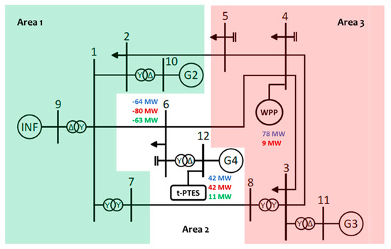
Figure 11.
Flexibility from t-PTES for mitigating unscheduled tie-line power flows due to variability from wind energy. Values shown in pre-event (shown in blue font), post-event (shown in red font), and after using t-PTES (shown in green font).
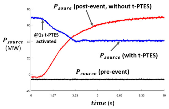
Figure 12.
Inter-area power flow (-ve sign is direction of power flow from bus1 into the bus6) under pre-event, post-event, and post-event recovery using t-PTES is shown. The black curve shows pre-event source output, the red curve shows pre-event tie-line flow (without t-PTES activated), and the blue curve shows post-event source output (with t-PTES activated post-event).
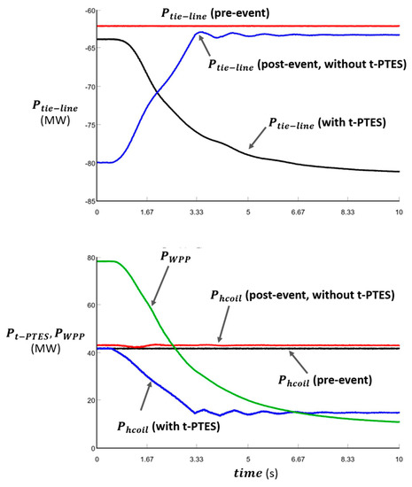
Figure 13.
Flexibility provided by t-PTES to regulate tie-line flow after a sharp drop in wind speed resulting in reduced power output (78 to 9 MW: green curve in bottom plot) in 10 s. Tie-line flow regulation through t-PTES operation is shown. In the top plot, the red curve shows pre-event tie-line flow (without t-PTES activated), the black curve shows post-event tie-line flow (without t-PTES activated), and post-event tie-line flow (with t-PTES activated). In the bottom plot, the heating coil output is shown: the black curve shows pre-event output, red shows the post-event (without t-PTES activated), and the blue curve shows the post-event output (with t-PTES activated).
5. Conclusions and Future Work
We presented physics-based modeling and simulation for t-PTES for the NPP to enable flexible operation under different dynamic scenarios. Digital real time simulations show the use of t-PTES can effectively improve the flexibility of the NPP, both at the plant level and for the area-level power system with renewable wind energy. Simple rule-based controls were developed to evaluate the concept through simulations for flexible NPP operation. The future work will consider a model of the NPP including thermodynamics and neutronics, to establish impacts of large disturbances and power deviation on the NPP output, and its value during natural disasters using coordinated control from the NFE. The NPP model verification and validation will be done with actual NPP data collected from a real-world NPP. Another approach to advance in the modeling of complex hybrid energy systems is the use of data-driven and physics-driven Machine Learning methods. These methods take advantage of the abundant high-fidelity data for transient operation of thermal systems and the, ever more accessible, high-performance computing capabilities. These emerging methodologies enable the integration of available governing equation with data from sensors to accurately predict the behavior and dynamic interaction among integrated systems. This work presented hybridization of the NPP using co-located t-PTES technology. Regionally located assets for hybridization will be explored in future work.
Author Contributions
Conceptualization—R.H., J.D.O. and M.P.; methodology—R.H., J.D.O., M.P. and J.C.O.; software—M.P., J.D.O. and J.C.O.; validation—J.D.O., M.P. and J.C.O.; formal analysis—J.D.O. and J.C.O.; investigation—R.H., J.D.O. and M.P.; writing—original draft preparation, R.H. and J.D.O.; writing—R.H., J.D.O. and M.P.; supervision, R.H., J.C.O. and C.C. The views expressed in the article do not necessarily represent the views of the DOE or the U.S. Government. All authors have read and agreed to the published version of the manuscript.
Funding
This research received no external funding.
Acknowledgments
We acknowledge help and modeling discussions from Camilo Ordonez at FAMU-FSU College of Engineering, Tallahassee, FL, USA.
Conflicts of Interest
The authors declare no conflict of interest.
Appendix A
State-space model of hot tank
A = [−U × A/()];
B = [1/() − 1/() U × A/()];
C = [1];
D = [0 0 0];
References
- Lake, J.A.; Bennett, R.G.; Kotek, J.F. Next Generation Nuclear Power. Sci. Am. 2009. Available online: https://www.scientificamerican.com/article/next-generation-nuclear/ (accessed on 18 June 2021). [CrossRef] [PubMed]
- Ontario Ministry of Energy. SMR Deployment Feasibility Study Feasibility of the Potential Deployment of Small Modular Reactors (SMRs) in Ontario; Ontario Ministry of Energy: Toronto, ON, Canada, 2016. [Google Scholar]
- Nian, V.; Zhong, S. Economic feasibility of flexible energy productions by small modular reactors from the perspective of integrated planning. Prog. Nucl. Energy 2020, 118, 103106. [Google Scholar] [CrossRef]
- Ingersoll, D.T.; Carelli, M.D. Handbook of Small Modular Nuclear Reactors, 2nd ed.; Elsevier: Amsterdam, The Netherlands, 2021; ISBN 9780128239179. [Google Scholar]
- Rämä, M.; Leurent, M.; de Lavergne, J.G.D. Flexible nuclear co-generation plant combined with district heating and a large-scale heat storage. Energy 2020, 193, 116728. [Google Scholar] [CrossRef]
- Suman, S. Hybrid nuclear-renewable energy systems: A review. J. Clean. Prod. 2018, 181, 166–177. [Google Scholar] [CrossRef]
- Gjorgiev, B.; Cepin, M. Nuclear Power Plant Load Following: Problem Definition and Application. In Proceedings of the 20th International Conference Nuclear Energy for New Europe, Bovec, Slovenia, 12–15 September 2011. [Google Scholar]
- Botterud, A.; Yildiz, B.; Conzelmann, G.; Petri, M.C. Nuclear hydrogen: An assessment of product flexibility and market viability. Energy Policy 2008, 36, 3961–3973. [Google Scholar] [CrossRef]
- Jenkins, J.D.; Zhou, Z.; Ponciroli, R.; Vilim, R.B.; Ganda, F.; de Sisternes, F.; Botterud, A. The benefits of nuclear flexibility in power system operations with renewable energy. Appl. Energy 2018, 222, 872–884. [Google Scholar] [CrossRef]
- Lokhov, A. Load-following with nuclear power plants. NEA News 2011, 29, 18–20. [Google Scholar]
- Borowiec, K.; Wysocki, A.; Shaner, S.; Greenwood, M.S.; Ellis, M. Increasing Revenue of Nuclear Power Plants with Thermal Storage. J. Energy Resour. Technol. 2020, 142, 042006. [Google Scholar] [CrossRef]
- Kim, Y.J.; Norford, L.K.; Kirtley, J.L. Modeling and Analysis of a Variable Speed Heat Pump for Frequency Regulation through Direct Load Control. IEEE Trans. Power Syst. 2015, 30, 397–408. [Google Scholar] [CrossRef]
- Ruhnau, O.; Hirth, L.; Praktiknjo, A. Time series of heat demand and heat pump efficiency for energy system modeling. Sci. Data 2019, 6, 1–10. [Google Scholar] [CrossRef] [PubMed]
- Osorio, J.D.; Rivera-Alvarez, A.; Abakporo, O.I.; Ordonez, J.C.; Hovsapian, R. Thermodynamic modeling of heat engines including heat transfer and compression-expansion irreversibilities. J. Therm. Sci. Eng. Appl. 2022, 14, 011001. [Google Scholar] [CrossRef]
- Jiang, S.; Annakkage, U.D.; Gole, A.M. A Platform for Validation of FACTS Models. IEEE Trans. Power Deliv. 2006, 21, 484–491. [Google Scholar] [CrossRef]
- Inoue, T.; Ichikawa, T.; Kundur, P.; Hirsch, P. Nuclear plant models for medium- to long-term power system stability studies. IEEE Trans. Power Syst. 1995, 10, 141–148. [Google Scholar] [CrossRef]
- Kundur, P. Power System Stability and Control, 1st ed.; McGraw-Hill, Inc.: New York, NY, USA, 1994. [Google Scholar]
- Nash, A.L.; Badithela, A.; Jain, N. Dynamic modeling of a sensible thermal energy storage tank with an immersed coil heat exchanger under three operation modes. Appl. Energy 2017, 195, 877–889. [Google Scholar] [CrossRef]
- Durantay, L.; Taillardat, J.-M.; Pradurat, J.-F.; Velly, N. State of the art for full electric driven refrigeration compressors solutions using adjustable speed drive: Which combination of technology platforms leads to the best capex & opex solution up to 100 MW? In Proceedings of the 2017 Petroleum and Chemical Industry Technical Conference (PCIC), Calgary, AB, Canada, 18–20 September 2017; pp. 477–486. [Google Scholar] [CrossRef]
- Holtz, J. Sensorless control of induction motor drives. Proc. IEEE 2002, 90, 1359–1394. [Google Scholar] [CrossRef] [Green Version]
- Akin, B.; Garg, N. Scalar (V/f) Control of 3-Phase Induction Motors; Application Report-SPRABQ8; Texas Instruments: Dallas, TX, USA, July 2013; p. 25. Available online: https://www.ti.com/lit/an/sprabq8/sprabq8.pdf?ts=1624634299969&ref_url=https%253A%252F%252Fwww.google.com%252F (accessed on 20 May 2021).
- Thiringer, T.; Luomi, J. Comparison of reduced-order dynamic models of induction machines. IEEE Trans. Power Syst. 2001, 16, 119–126. [Google Scholar] [CrossRef]
- ABB Synergy Torque-Speed Curve and Load Inertia.pdf. Available online: https://search.abb.com/library/Download.aspx?DocumentID=9AKK107045A5113&LanguageCode=en&DocumentPartId=&Action=Launch (accessed on 20 May 2021).
Publisher’s Note: MDPI stays neutral with regard to jurisdictional claims in published maps and institutional affiliations. |
© 2021 by the authors. Licensee MDPI, Basel, Switzerland. This article is an open access article distributed under the terms and conditions of the Creative Commons Attribution (CC BY) license (https://creativecommons.org/licenses/by/4.0/).