Article

Practical and Economical Effects of the Use of Screen Meshes for Steel Nitriding Processes with Glow Plasma

1
Faculty of Mathematics and Natural Sciences Jan Długosz Academy in Częstochowa al. Armii Krajowej 13/15, Starzyńskiego Street 1/9, 42-200 Czestochowa, Poland
2
Faculty of Process, Material Engineering and Applied Physics, Czestochowa University of Technology, 42-200 Czestochowa, Poland
3
Department of Electrical Engineering, Czestochowa University of Technology, 42-201 Czestochowa, Poland
*
Author to whom correspondence should be addressed.
Energies 2021, 14(13), 3808; https://doi.org/10.3390/en14133808
Submission received: 15 April 2021 / Revised: 16 June 2021 / Accepted: 21 June 2021 / Published: 24 June 2021
(This article belongs to the Special Issue Improvements of the Electricity Power System)

Abstract

:
The dynamically developing energy sector forces technologists to create new materials that meet the increasingly higher mechanical, chemical, and electrical requirements. The paper relates to the method of reducing the energy consumption of the plasma nitriding process of austenitic steels. The method proposed by the authors involves the modification of nitriding technology in glow plasma. It consists of introducing perforated screens between the anode and nitrided surface made of a material with a composition similar to the processed material and the use of an HF power supply with controlled mean current generating negative voltage peaks of about 1000 V. Nitriding is carried out in a nitrogen-hydrogen atmosphere. The processed material has a negative potential in relation to the surrounding plasma and strongly negative in relation to the vacuum chamber jacket. The actual treatment is preceded by ionic cleaning of the surface of the detail and heating it to the temperature that activates the diffusion processes. The authors analyse the dynamic distribution of electric fields generated at the surface of the nitrided material with different configurations of the cathode-sample-screen system, trying to find the correlation of treatment parameters with the parameters of the nitrided layer. A significant influence of the screening meshes on the depth of the obtained diffusion layers containing nitrogen was found. The oscilloscopic measurements of the plasma in the boundary layer allowed for the observation of voltage peaks, probably leading to an increase in the peak kinetic energy of nitrogen ions and their easier penetration into the material. The work is of a cognitive nature and is probably one of the first to look for relationships between the dynamic electrical parameters of plasma and the efficiency of nitriding.

1. Introduction

In many research centres, research has aimed at creating new and increasingly perfect materials in order to improve their properties, namely the electrical [1], chemical [2], or mechanical [3] properties. Diffusion and ion nitriding of steel are some of the methods for enhancing the service properties of the top layer. This results in a substantial increase in hardness and wear resistance as well as a moderate improvement in corrosion resistance.
Nitriding significantly extends the life of durable machine parts [4,5,6]. It is extremely important from the point of view of implementing newer technologies in the broadly understood energy sector. It is necessary to use an increasing number of materials with higher mechanical strength, with improved wear resistance and electrical conductivity, as well as better chemical and anti-corrosion properties. The achieved effects involve a greater, thicker, and more homogeneous nitrided layer [7].
The properties of the nitrided layer depend on the thickness of the nitride surface layer as well as the chemical and phase composition, and the effective depth of the casing [8,9,10,11,12].
Classic gas nitriding technologies are increasingly often substituted with plasma or ion technologies, which are attractive due to shorter treatment times, lower unit energy expenditure, and better properties of produced layers [13,14,15,16,17,18]. The treatment is usually carried out in vacuum chambers, where space is filled with working gas at a pressure of several millibars. The plasma is generated in the stable high voltage electrostatic field or by use of sinusoidal high-frequency modulation of the voltage. The part being treated has a negative potential relative to the plasma that surrounds it, and a strongly negative potential with respect to the chamber jacket. The treatment condition can be preceded by ion cleaning. An interesting solution are the works [19,20] in which the authors placed the sample inside a perforated hollow cathode. Ions falling through the holes in the cathode hit the surface of the sample placed on the ceramic insulator with considerable kinetic energy. Of course, some of the ions neutralise their positive charge through contact with the electron gas filling the cathode. The nitriding technique proposed by the authors consists in the simultaneous influence of ions and atoms with high kinetic energy and momentum vector perpendicular to the sample surface. This has a significant impact on the intensity of the nitriding process while maintaining the optimum temperature due to the processes that may take place inside the material.
The authors of the nitriding method proposed in this article place the nitrided element on the cathode in a similar way as in typical plasma nitriding. A new element, being the essence of the technical solution, is the placement of a screening mesh made of perforated titanium sheet between the workpiece and anode. It causes the following phenomena:
  • Accelerating the velocity of ions falling into the space between the lattice and cathode;
  • Emission of light radiation, which can have a significant impact on the energy on the surface of the sample, causing, among other things, a reduction of the electron output energy and the creation of a strong electric field gradient which additionally accelerates the ions bombarding the sample;
  • Amplification of plasma waves in the space between the sample and mesh, which in this case acts as a screen.
The course of dynamic processes taking place in the plasma was controlled with the use of voltage probes placed in different areas of the space between the surface of the sample and the screening mesh. Current-voltage waveforms of the power supply system and the sample temperature were recorded simultaneously. The final treatment results were assessed by classical metallographic tests and measuring the depth of the layers saturated with nitrogen using the GDEOS method. The strong, variable electromagnetic fields existing at the sample surface help nitrogen ions to overcome potential barriers occurring on the surface and probably have an advantageous effect on the phase equilibrium systems in the material being treated by facilitating the dissolution of nitrogen in the solid phase and its diffusion into the material. These fields can be modified quantitatively and qualitatively with the use of appropriately configured screen grids.
The screen is constructed as a one-sided open cylinder (without one base) with the diameter of 200 mm and the height of 150 mm. Evenly spaced holes with the diameter of 4.5 mm were laser cut in a cylindrical shell.
The results reported in the paper serve surveying purposes. They were intended to relate to the modifications made in the configuration of the glow-discharge plasma nitriding stand to the intensity of the nitriding process and the nature of produced top layers. The presented study is purely experimental in character.

2. Results

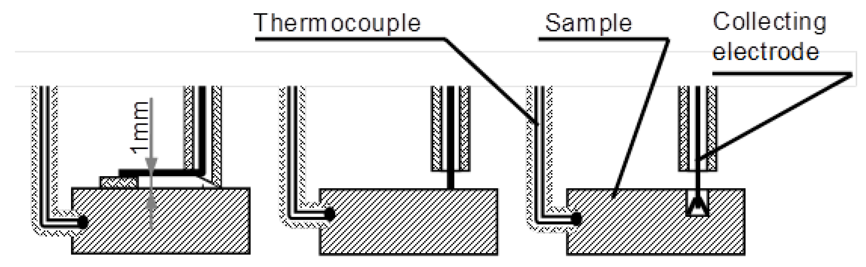
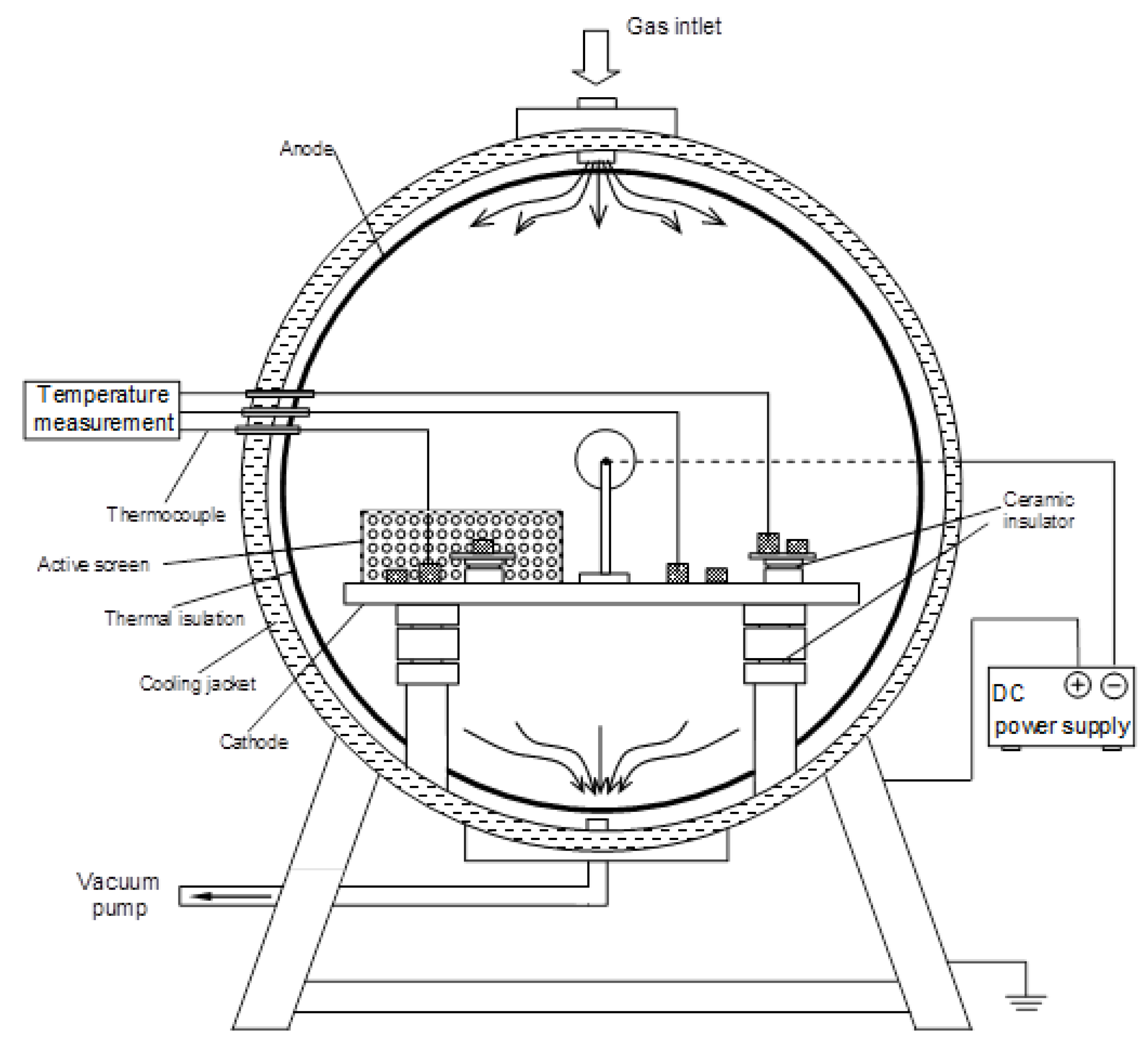
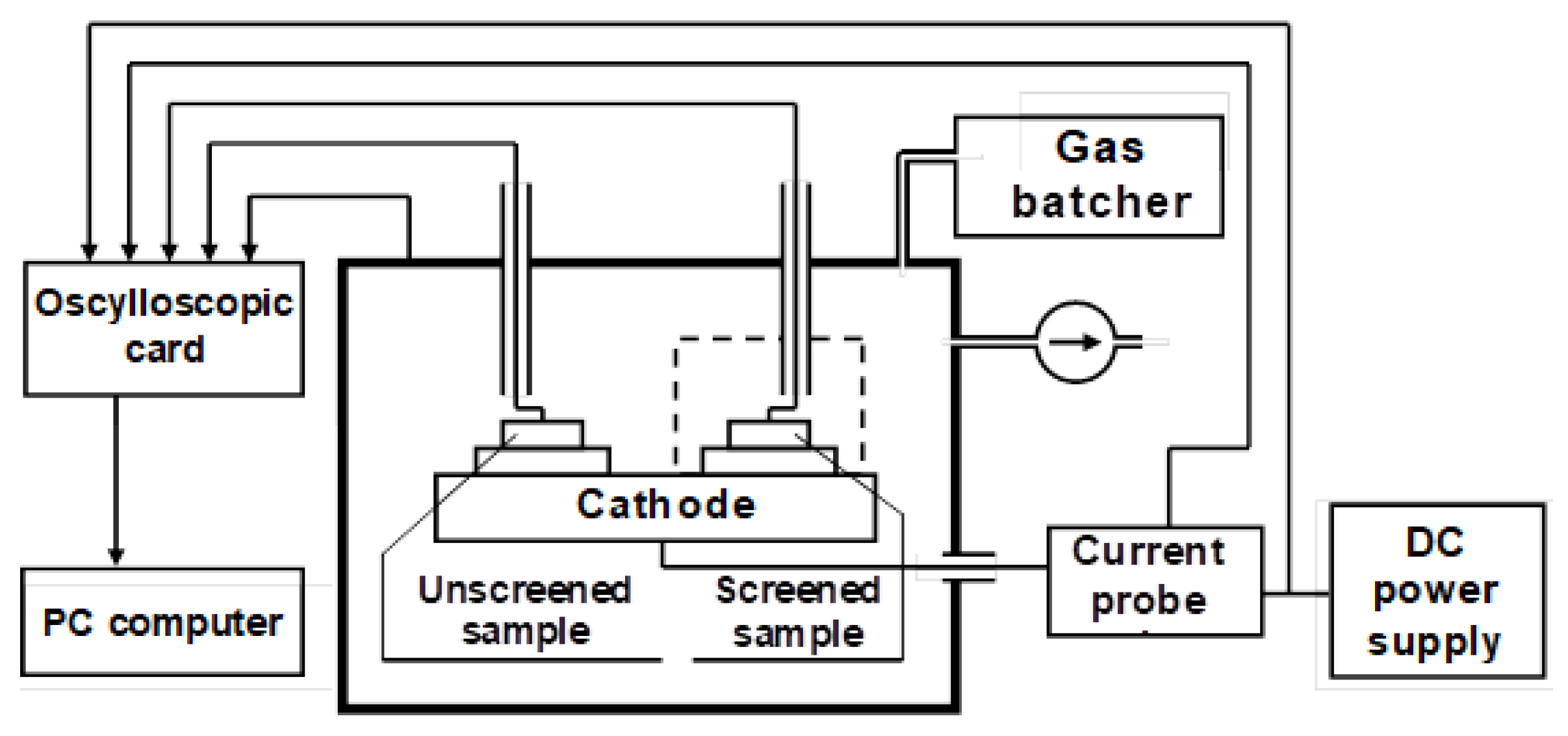
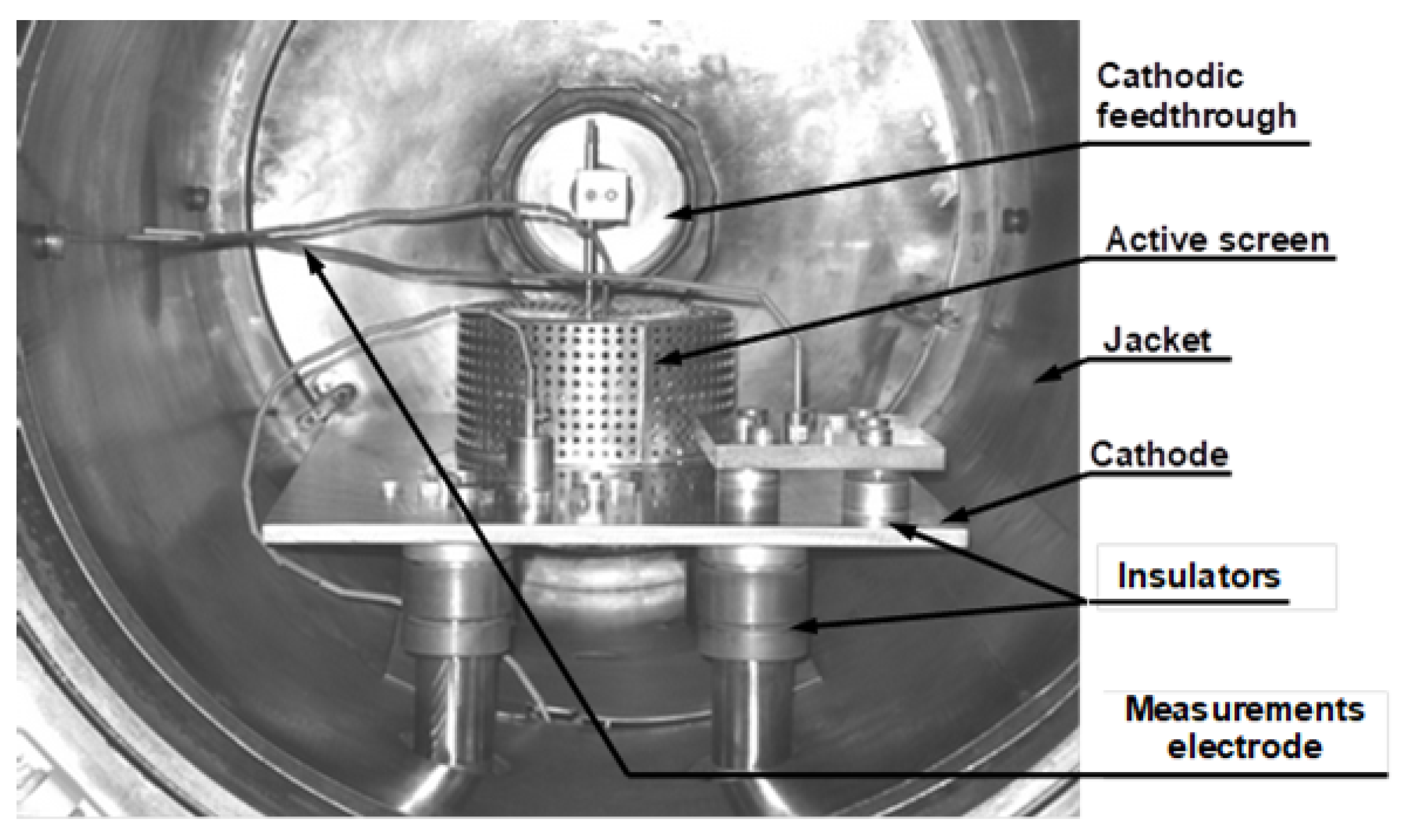
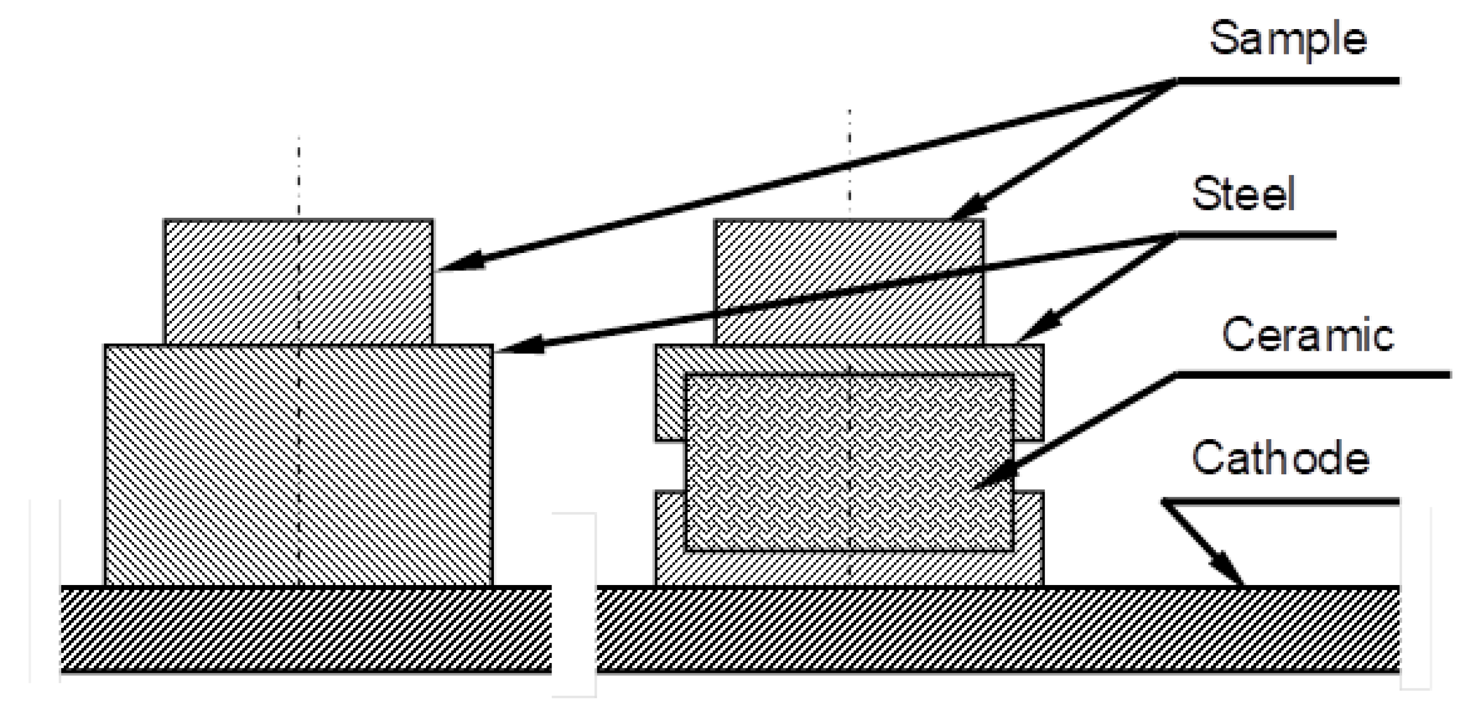
2.1. Configuration of the Testing Stand

The testing stand consists of a glow-discharge furnace (vacuum chamber), a power supply, a pump-metering assembly, a control and measuring unit, and a closed-circuit water cooling system. The working chamber of the furnace as shown in Figure 1 has the following dimensions: Diameter ϕ = 400 mm and depth h = 600 mm. The grounded chamber jacket makes the anode. The cathode, in the form of a rectangular prism plate of maximum dimensions of 455 × 168 × 14 mm, is positioned inside the chamber on a set of ceramic distance blocks. The cathode is power supplied through the bushing in the back wall of the chamber. Samples to be nitrided are arranged on the cathode symmetrically to the furnace axis. Depending on the nitriding variant, the samples either have galvanic contact with the cathode or are insulated from it with ceramic insulators.
In terms of the morphology and structure of the layer obtained from nitriding on the cathode and on the cathode using a supporting screen, they did not differ significantly, except that during the nitriding on a cathode with an active screen, a significant increase in the thickness of the middle zone of the layer is produced, i.e., Cr 2 N nitride zones. When analysing the structure of the layers obtained from nitriding in the plasma potential with the aid of a supporting screen, it can be seen that in comparison with the variants of nitriding at the cathode, the CrN nitride zone is reduced, while the zone of austenite supersaturated with nitrogen increased. This is shown in Figure 2.
The temperature of the samples are monitored using thermocouples. The potentials of the samples and the potential of the plasma in their immediate vicinity are measured using electrodes isolated from the furnace atmosphere with ceramic tubes; these electrodes are not shown in Figure 1. The measuring system conductors are passed out of the furnace via bushings in the jacket wall. The screened and unscreened samples are positioned on the cathode at an identical distance from the plane of symmetry of the chamber. The complete setup of the testing stand is illustrated in Figure 3.
The screen is made in the form of a unilaterally open perforated steel sheet box having galvanic contact with the cathode plate. The pump-metering equipment enables introducing the gas mixture to the chamber and keeping the fixed pressure on the required level. In the ion cleaning process, an Ar–H 2 mixture was used. The nitriding processes were conducted using N 2 –H 2 mixtures at pressures of the order of 150 Pa. The processes were run in variants differing in temperature. The temperature was controlled by changing the power fed from a high-frequency power supply. The chopper-type power supply generates packets of unipolar pulses of a frequency up to 100 kHz and a voltage of approximately 1 kV. The power is controlled by an infinite variable adjustment of the packet fill degree and step adjustment of the energy of a single pulse. The current-voltage characteristics of the power supply experimentally taken under typical conditions of operation with the plasma furnace are shown in Figure 4. In the presented feeding system, plasma is an inductive element and has simultaneously self-resistance and capacity. All physical characteristic of the plasma are variable.
The visible steep peaks are probably due to the inductive influence of the plasma. The sampling frequency adopted in this measurement did not allow the power supply fundamental carrier frequency to be recorded, which in this case was 64 kHz, and was strongly attenuated by the receiver’s system. However, a clearly distinguished sub-harmonic of 32 kHz is visible in the voltage waveform of the Fourier transform spectra shown in Figure 5.
The graphs of the Fourier transforms of successively recorded voltage waveforms did not exhibit complete repeatability. Clear differences are visible in the region of low frequencies (up to 8 kHz). These are likely to be caused by transient phenomena occurring in the plasma.
The measuring unit consists of classic pressure and temperature measuring systems and two DSO-2090 two-channel oscilloscope cards of a maximum resolution of 4 ns, operating in parallel. In addition to the classic functions of a digital oscilloscope, these cards enable the computation of the Fourier spectra of recorded waveforms. Aside from recording voltage signals and their Fourier spectra, screenshots of the oscilloscope panel were also recorded. This provided an additional safeguard against making any gross errors. A general view of the measuring stand with the furnace’s interior is shown in Figure 6.
Test samples (see Figure 7) were made in the form of rectangular prisms of a base of 20 × 15 mm and a height of 15 mm.
The test samples were placed on the cathode plate in two variants, either on ceramic insulators or on steel separator blocks with the size of the insulator. The separator blocks were used to eliminate any influence of sample positioning on the glow-discharge treatment process. Thermocouples for temperature measurement were installed in the holes in the side part of the sample. Measuring electrodes were installed in holes drilled on the sample surface either with direct contact with the surface or in the plasma potential at a distance of 1 mm from the sample surface. The arrangement of measuring electrodes is shown in Figure 8.
The course of the process could be observed visually through the window in the chamber’s front wall.
For both variants, the results of treatment conducted either with or without the aiding screen were compared. In this paper, the authors focused on the physical phenomena caused by screening. Therefore, results have been reported.
Under the same process conditions, a screened sample and an unscreened sample were treated simultaneously. Due to their symmetrical position in the furnace chamber, the influence of the treatment assembly’s geometry on the obtained results was eliminated.
For each variant, the diffusion effects were determined and the waveforms of voltages taken up by the electrodes were measured with different sampling time bases. Research was carried out using austenitic steel AISI 316L that contains: 0.02C, 16.82Cr, 10.07Ni 1.58Mn, 2.07Mo, and Fe, which is the remaining part. Process was conducted on a pressure of 150 Pa in mixture 25% N 2 and 75% H 2 with a temperature between 430–490 C. The selection of nitriding parameters was, among other things, aimed at producing hard and wear-resistant chromium nitrides in the surface layer, as seen in Figure 2. The main treatment, lasting 5–14 h, was preceded by the ionic cleaning of thesurface in the atmosphere of argon—nitrogen. Treated surface was investigated for nitrogen diffusion depth into the surface layer using method GDEOS. Obtained measurements were compared to the nitrogen diffusion depth of gas nitrided austenitic steel AISI 301 and presented in Table 1.
The screening effect of the grid was manifested mainly by the increase of nitrided layer depth, which for the galvanic isolated sample (from cathode and anode—in plasma potential) was over 10 times thicker compared to the nitrided layer in the sample treated in similar thermodynamic conditions without using a screen. Utilisation of a screen, in case of nitriding on cathode for 5 h in a temperature of 430 C, resulted in over a two-fold increase of nitrogen diffusion depth. Extension of time and increase of temperature during treatment with screen resulted in an almost four-fold increase of nitrided layer depth comparing to cathode nitriding without usage of screen. Thickness of nitrided layers that are obtained by conventional gas nitriding are comparable to the layers obtained by glow-discharge cathode nitriding, but are significantly lower than in the case of treatment with the usage of a screening grid. Taking into consideration the significant increase of the layer’s thickness and hardness after the nitriding process, it should be expected that the wear resistance should be considerably greater.

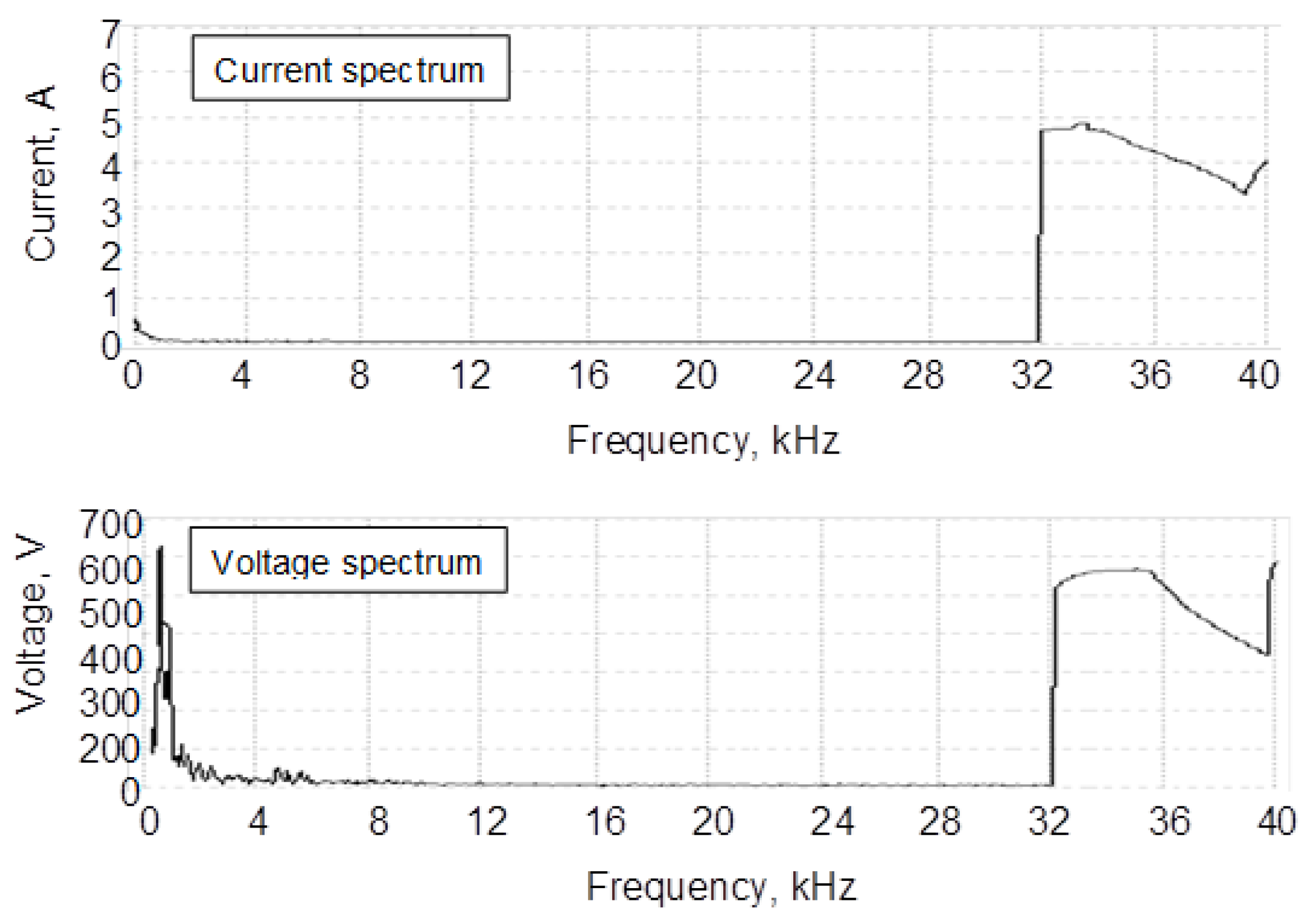
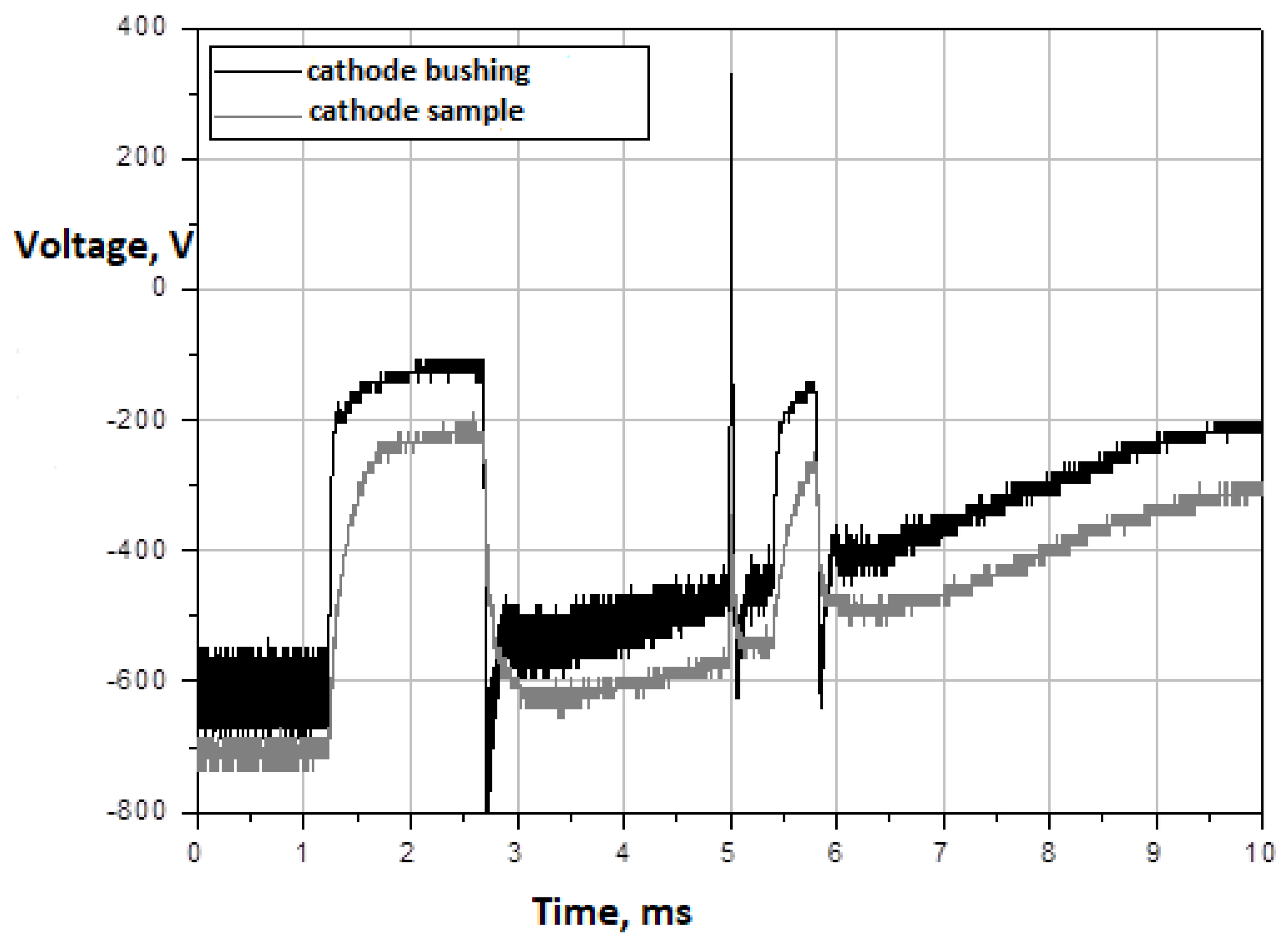
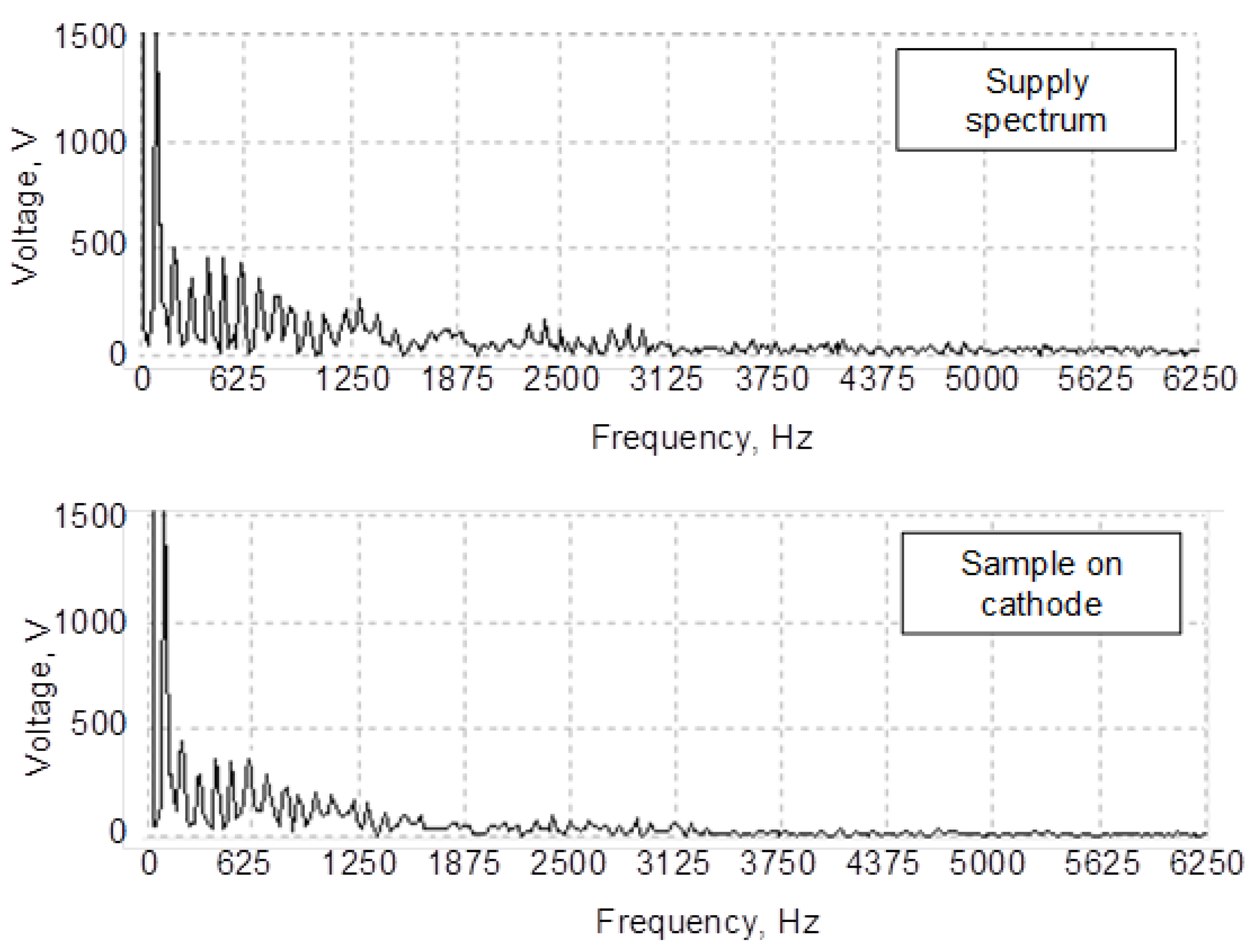
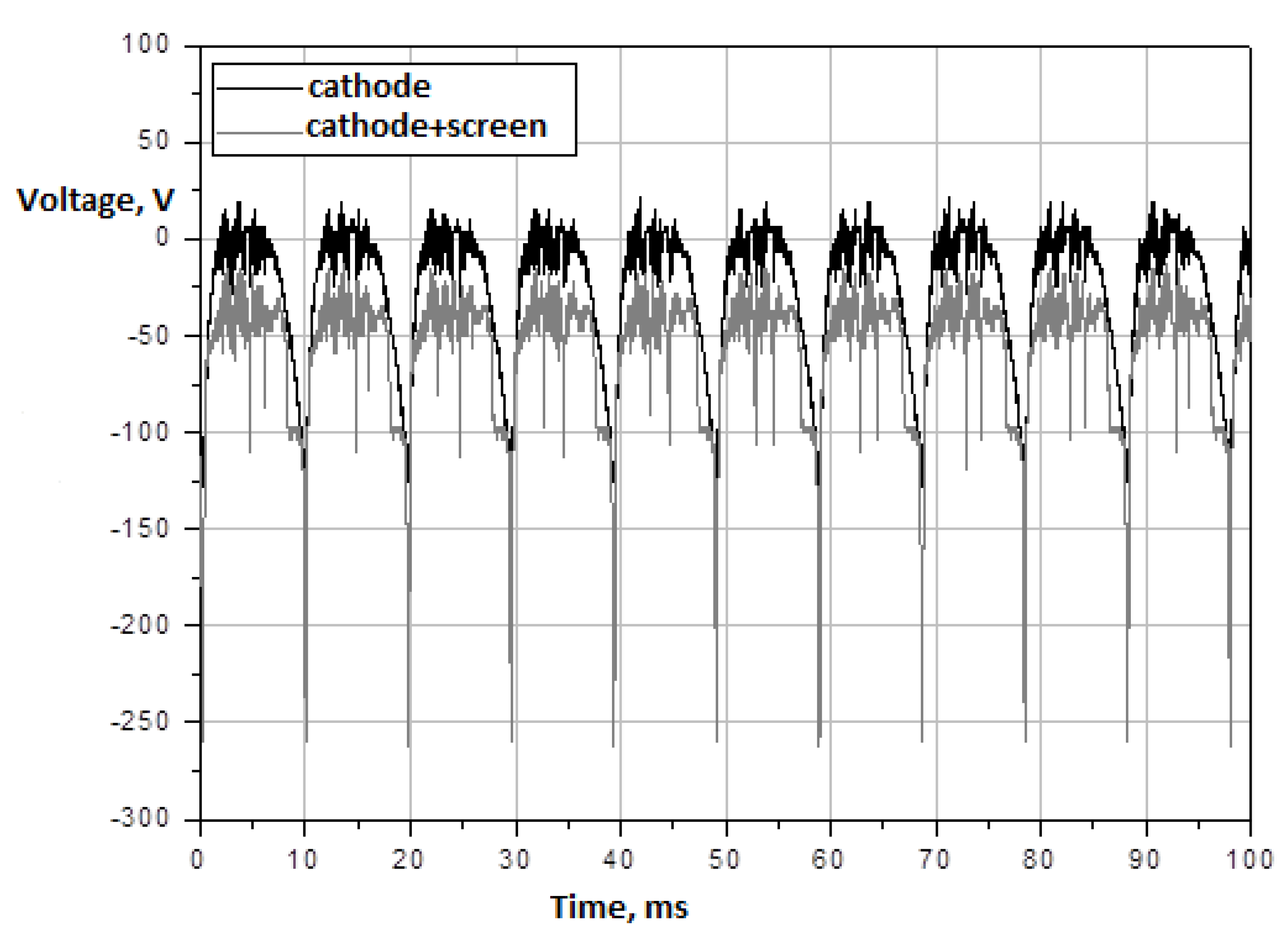
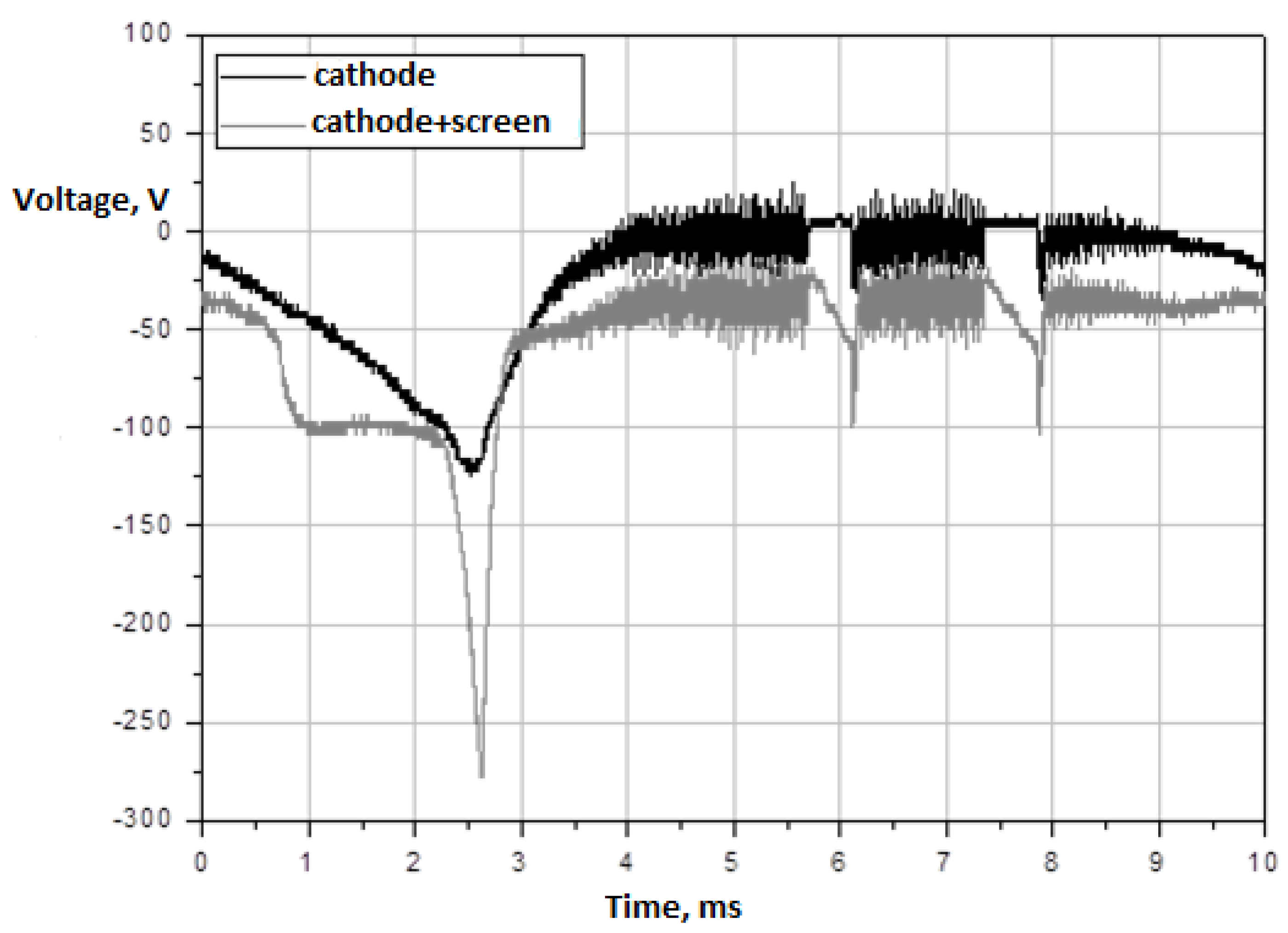
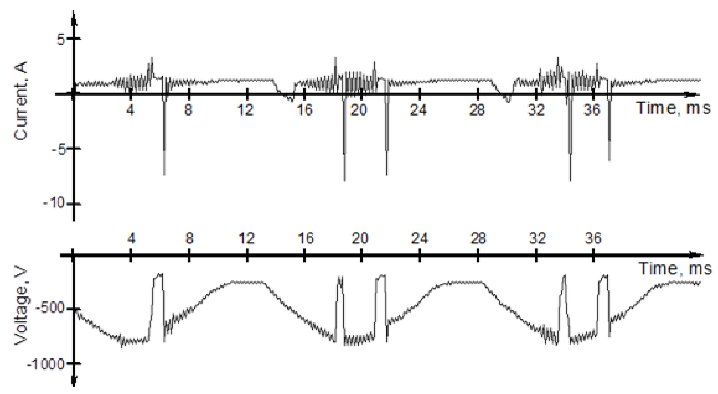
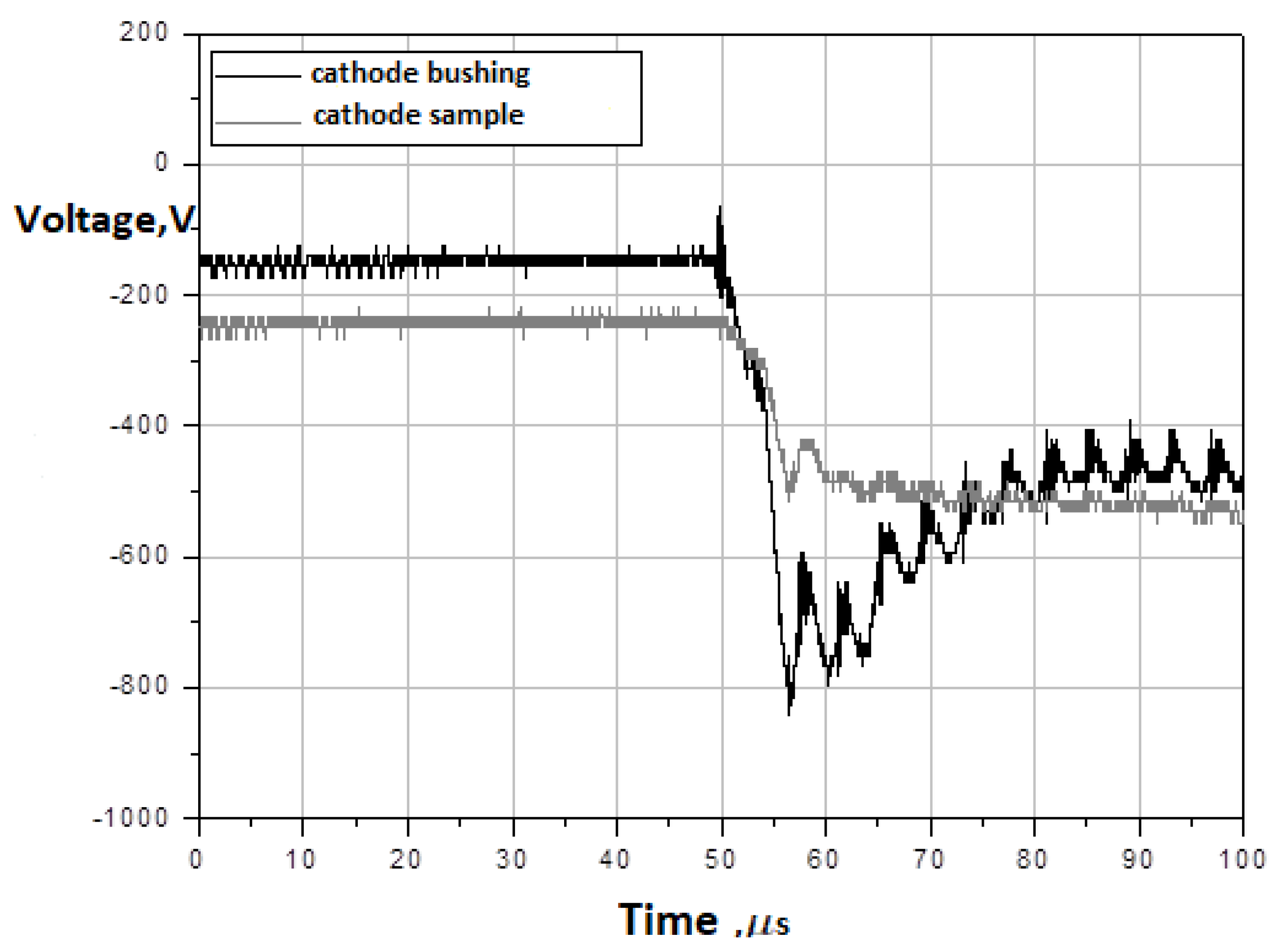
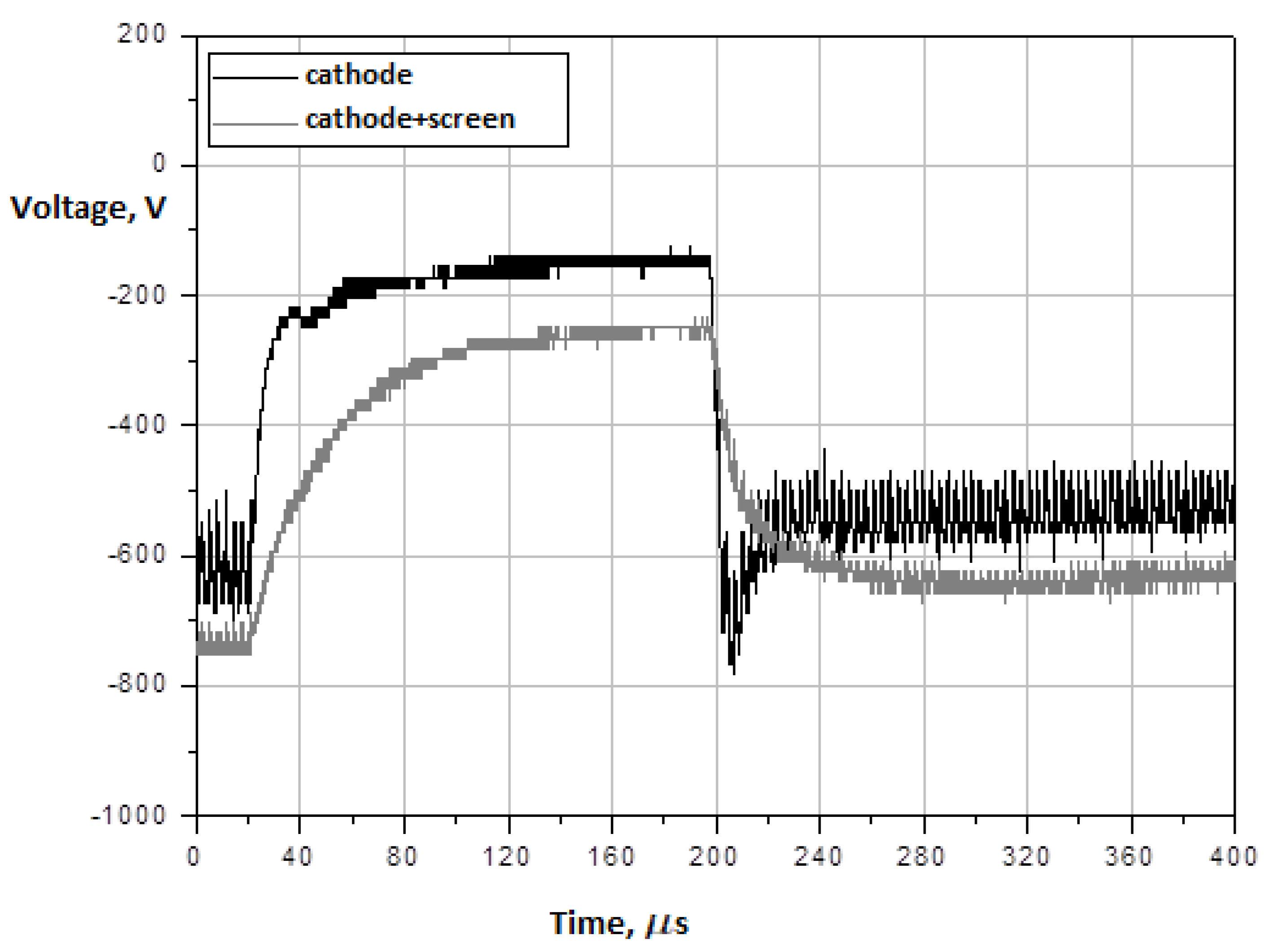
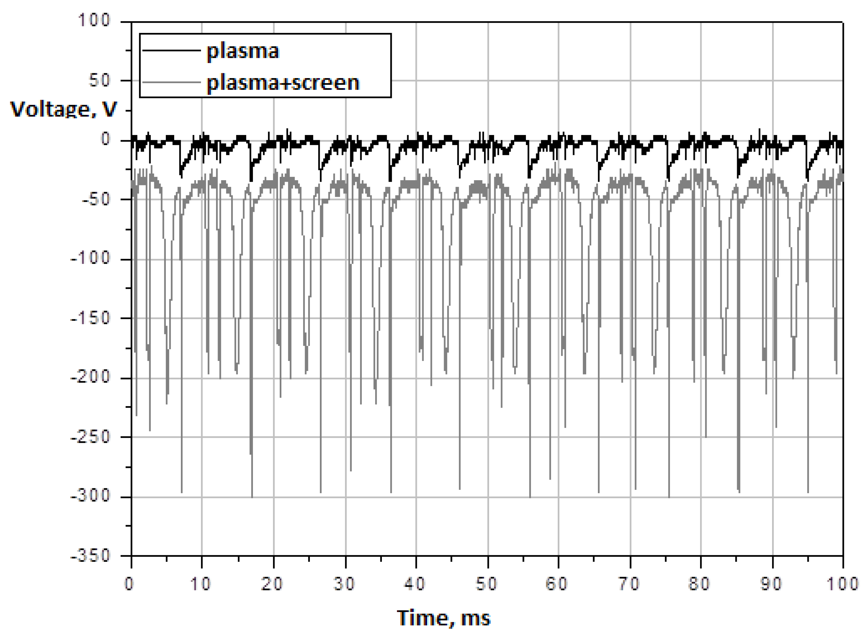
2.2. Analysis of Cathode Voltages

The relatively large mass of the cathode and its dynamic interaction with the plasma make the voltage waveforms at the power supply’s output different from those measured directly on the cathode. Usually, this is due to the attenuation of high frequencies and short-duration pulses with a steep rising edge. However, in the case of using a screen, a reverse phenomenon might occur, that is the amplification of some components in the high frequency region.
The waveforms shown in Figure 9 and Figure 10 illustrate the effect of attenuation of the high components of the power supply voltage waveform taken from the same testing stand configuration with different time bases. Obviously, the choice of the waveform recorded at small time bases is random in character.
The differences between the driving voltage and the waveform actually observed on the sample surface are clearly visible in the Fourier spectra shown in Figure 11 with longer observation durations.

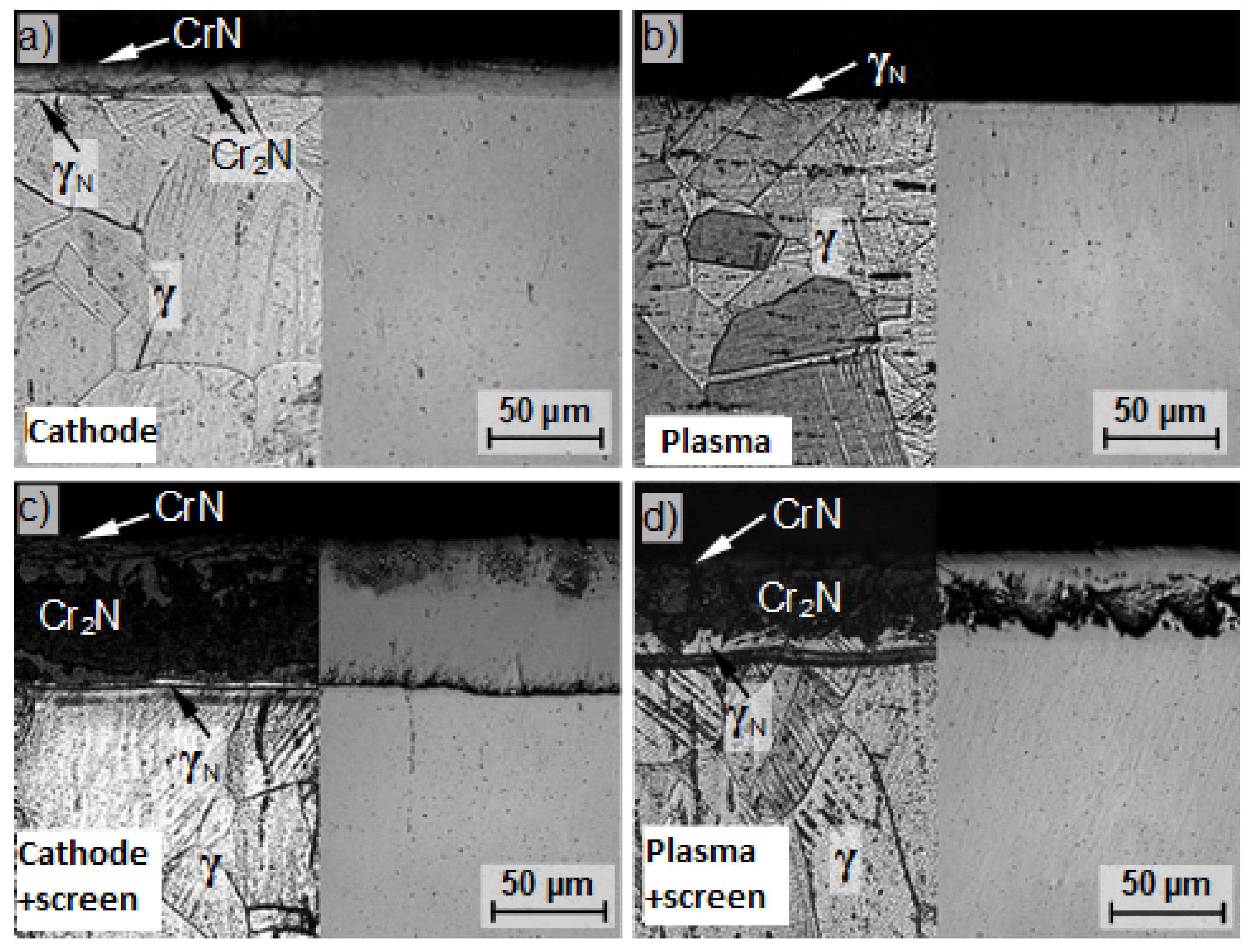
2.3. Treatment of Parts with Galvanic Contact with the Cathode

Introduced screens have little effect on the voltage waveforms recorded directly on the sample surface. The effect is noticeable more when recording with the time base near the 200- μ s border. This influence can be seen in Figure 12.
In Figure 13 and Figure 14, a filtrating effect of the screen for frequencies above 10 kHz is visible with a simultaneous increase in the constant component by 50–80 V. However, this phenomenon does not explain the increases in the thickness of non-nitrided layers, which are found in metallographic examination. Admittedly, the increase in temperature has a favourable effect on the diffusion process, but temperature increases in the order of several dozen degrees may produce the effects of increasing the layer thickness by a few percent at most.
The solution should have therefore been sought for in the phenomena occurring in the wall boundary layer. This was confirmed by a series of measurements taken at a distance of 1 mm from the sample surface. Introducing the screen increased the maximum amplitude peaks by almost two times and markedly increased the intensity of the medium and low harmonic components of the main period.
At the same time, the constant component was shifted by several dozen volts. As a curiosity, the absence of the screen’s filtrating effect with respect to high voltage waveform frequencies, and even their slight amplification, can also be noticed. All of these phenomena favour the occurrence of high-energy nitrogen ions within the sample wall boundary layer, which are able to penetrate into the material, thus substantially influencing the parameters of the diffusion layer being formed.

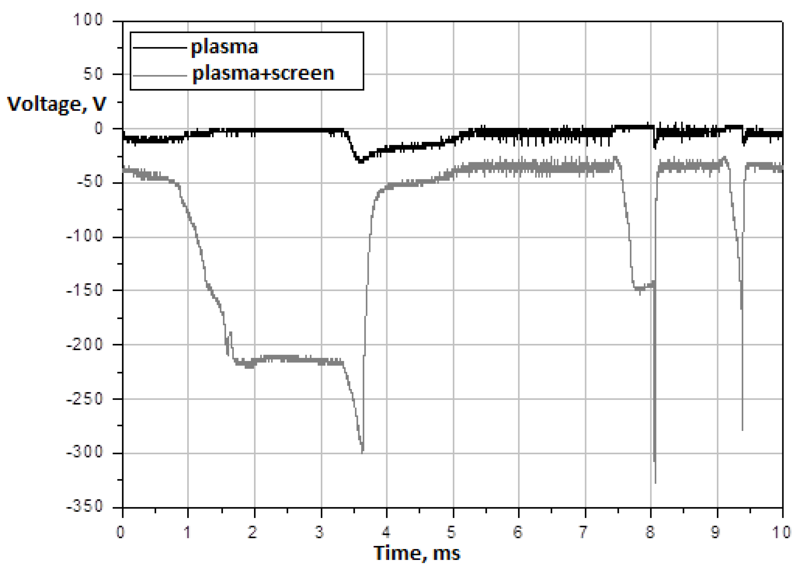
2.4. Treatment of Parts Insulated from the Cathode

The effect of the screen proved especially significant in the case of treating parts with no galvanic contact with the cathode. Under normal conditions, the intensity of the nitriding process is very low, and the process is only conducted in instances where there are difficulties in employing the basic treatment variant. The use of the screen has resulted in an increase in the intensity of the saturation process, and measurable differences in voltage waveforms occur both in the wall boundary layer and on the surface of the part. Particularly prominent differences occur in wall boundary layers (see Figure 15 and Figure 16).
Significant differences, not only quantitative but also qualitative, are visible. On the surface of the sample under the screen, additional peaks appear, including those with magnitudes more than 10 times the maximum amplitudes of voltage changes on the control sample. The low harmonics of the basic waveform are amplified. At the same time, the mean voltage value remains shifted by several dozen volts towards negative values.
The spectral analysis has shown that the screen causes the amplification of frequencies in the range of 100–500 Hz and the occurrence of numerous new peaks in the range of 500–2500 Hz. An interesting phenomenon occurs at the same time: The high frequencies brought in by the power supply, which were suppressed on the surface of the samples with galvanic contact with the cathode, reappear and are well observable in wall boundary layers both at the screened sample and at the sample treated without the screen.

3. Conclusions and Hypotheses

The research carried out has revealed the particular role of phenomena occurring in the wall plasma boundary layer of the part being treated. The formation of this layer was significantly influenced by the employed screens. It caused changes in the current-voltage waveforms, which are particularly prominent in the range of up to 2.5 kHz. The observed waveforms were a superposition of the stochastic component and quasiperiodic waveforms with the main period forced by the operation of the high-frequency power supply. Steep voltage peaks came up in the top layer region, which interacted with nitrogen ions occurring in this region. For the adopted treatment parameters, the mean free path was approx. 0.7 mm and corresponded to the thickness of the layer in which the amplification of the dynamic voltage waveforms occurred. The duration of the ion peaks favoured giving high velocities to the ions, corresponding to a kinetic energy of several dozen or several hundred electron volts. These ions embedded in the material to form a highly disequilibrium nitrogen-supersaturated zone in the top layer. This, in turn, promoted the diffusion of nitrogen into the material. Due to the large concentration gradients, the diffusion, at least at its initial stage, did not need to proceed along grain boundaries, which, in turn, favoured the formation of nitrided layers of high homogeneity. Similar phenomena should also occur without the screen in the strong cathode fall at a very sample surface however, due to the small zone thickness, the quantity of participating ions was considerably smaller than in the case of the thick wall boundary layer induced by the screen influence.
The above hypothesis of the predominant importance of voltage waveforms in the wall boundary layer of the thickness of 1–2 lengths of the free ion path explains the higher intensity of the process of nitriding samples insulated, but positioned under the screen compared to that of samples having galvanic contact with the cathode. The fact of the highest process efficiency in the case of screened samples galvanically connected with the cathode is also understandable. In this case, two synergic effects were present:
  • The effect of electric field acceleration of ions occurring at a distance approximate to the mean free path relative to the surface being treated;
  • The effect of additional acceleration of ions that were found within the zone of surface interaction of the intensive cathode fall.
The authors of the paper [22] report that for the cases analysed, the economic efficiency of active screen nitriding with respect to cathodic nitriding is as follows: The economic efficiency of electricity was 23.7% to 51.5%, and economic efficiency of the cost of consumption of gaseous media reached up to 76.4%.
An open problem is the mechanism of formation of the observed distribution of electric fields. It can be assumed that the screen forms a kind of a resonance cavity for the plasma waves forming in the chamber, which are induced by, among other things, the not very stable operation of the high-frequency power supply. The wave nature of the generation of variable electromagnetic fields under the screen was supported by the observation of periodical flashes showing up in the screen holes.
The generation of single, strong, and very narrow current-voltage pulses might also be caused by the phenomenon of plasma generation in the area limited by the screen box and in the adjacent sub-areas. We could also deal here with the screen trapping ions occurring in the screen’s surroundings and their interaction with the outer screen walls, which in turn led to the spatially and time-unstable electron emission and localised fluctuations in the degree of ionisation of the gas filling the box. The latter interpretation is supported by the intensive knocking out of atoms from alternatively used titanium screens, which manifests itself in, among other things, the intensive deposition of titanium nitride on the sample surface.
The variations in the distributions of nitrogen ion velocities in the wall boundary layer and the kinetic interactions of highly accelerated ions with the material being treated seem to be the most natural explanation of the positive influence of screens on the thickness and properties of produced diffusion layers. However, other seemingly less obvious hypotheses cannot be excluded. The plasma under the screen intensively glows within a wide spectrum range, including the UV region. Nitrogen is photoactive. Active nitrogen atoms may destroy the passivating films formed on chromium steel surface as a result of oxygen residue traces which cannot be completely eliminated from the chamber even when the process is carried out very carefully. The high spatial-time fluctuations in electric fields in the screened wall boundary layer might affect the phase equilibrium state of the material being treated. Therefore, the effect of an electric current, strong and dynamically varying electric fields and accompanying magnetic phenomena on the solubility of nitrogen in respective phases, including austenite, and blocking or simulating the formation of specific types of precipitates seems highly probable. These phenomena are still poorly understood, although in the literature there are some descriptions of anomalies in the phase equilibrium of carbon, silicon, and boron solutions, therefore research in this field should be continued. The results of the research presented in this article show that the use of screen meshes for the processes of steel nitriding with glow plasma has a high cognitive potential and may solve many unsolved problems.

Author Contributions

Conceptualisation, J.P., T.F., T.P. and M.S.; methodology, J.P., T.F., M.S. and T.P.; validation, T.F. and M.S.; formal analysis, J.P., T.F. and M.S.; investigation, T.F., M.S. and T.P.; data curation, J.P. and M.S.; writing—original draft preparation, T.F., M.S. and T.P.; writing—review and editing, T.F., M.S. and T.P.; theoretical modelling, T.F. and M.S.; software, T.F. and M.S.; visualisation, T.F., M.S. and T.P.; supervision, J.P.; project administration, T.F., M.S. and T.P.; funding acquisition, T.F., M.S. and T.P. All authors have read and agreed to the published version of the manuscript.

Funding

This research received no external funding.

Conflicts of Interest

Authors declare no conflict of interest.

References

  1. Eremin, V.A.; Solodyankin, A.A.; Belyakov, S.A.; Khodimchuk, A.V.; Farlenkov, A.S.; Krainova, D.A.; Saetova, N.S.; Kuzmin, A.V.; Artamonov, A.S.; Steinberger-Wilckens, R.; et al. Formation of Conductive Oxide Scale on 33NK and 47ND Interconnector Alloys for Solid Oxide Fuel Cells. Energies 2019, 12, 4795. [Google Scholar] [CrossRef] [Green Version]
  2. Ding, J.; Qin, W. Recent advances in potentiometric biosensors. TrAC Trends Anal. Chem. 2020, 124, 115803. [Google Scholar] [CrossRef]
  3. Braceras, I.; Ibáñez, I.; Dominguez-Meister, S.; Sánchez-García, J.A.; Brizuela, M.; Larrañaga, A.; Garmendia, I. Plasma nitriding of the inner surface of stainless steel tubes. Surf. Coat. Technol. 2018, 355, 116–122. [Google Scholar] [CrossRef]
  4. Sun, J.; Tong, W.P.; Zhang, H.; Du, X.D.; Wu, Y.C. Enhanced strength and plasticity of gas nitrided iron by surface mechanical attrition pretreatment. Surf. Coat. Technol. 2016, 286, 279–284. [Google Scholar] [CrossRef]
  5. Boniardi, M.; D’Errico, F.; Tagliabue, C. Influence of carburizing and nitriding on failure of gears—A case study. Eng. Fail. Anal. 2016, 13, 312–339. [Google Scholar] [CrossRef]
  6. Bindumadhavan, P.N.; Makesh, S.; Gowrishnkar, N.; Wah, H.-K.; Prabhakar, O. Aluminizing and subsequent nitriding of plain carbon low alloy steels for piston ring applications. Surf. Coat. Technol. 2000, 127, 251–258. [Google Scholar] [CrossRef]
  7. Wolowiec-Korecka, E.; Michalski, J.; Kucharska, B. Kinetic aspects of low-pressure nitriding process. Vacuum 2018, 155, 292–299. [Google Scholar] [CrossRef]
  8. Ozdemir, I.B.; Akar, F.; Lippmann, N. Parameter optimization of nitriding process using chemical kinetics. Metall. Mater. Trans. 2016, 47, 6169–6172. [Google Scholar] [CrossRef]
  9. Ozdemir, I.B.; Akar, F.; Lippmann, N. Local dynamics of chemical kinetics at different phases of nitriding process. J. Mater. Eng. Perform. 2015, 24, 2984–2989. [Google Scholar] [CrossRef]
  10. Mydłowska, K.; Myśliński, P.; Szparaga, Ł; Ratajski, J.; Gilewicz, A.; Jędrzejewski, R. Analysis of thermal stability of CrCN coatings deposited on nitrided substrates using modulated temperature thermodilatometry. Arch. Metall. Mater. 2017, 62, 771–776. [Google Scholar] [CrossRef] [Green Version]
  11. Jordan, D.; Antes, H.; Osterman, V.; Jones, T. Vacuum nitriding of 4140 steel Heat. Heat. Treat. Prog. 2008, 3–4, 33–38. [Google Scholar]
  12. Roliński, E.; Sharp, G. The effect of sputtering on kinetics of compound zone formation in the plasma nitriding of 3 Cr-Mo-V steel. J. Mater. Eng. Perform. 2001, 10, 444. [Google Scholar] [CrossRef]
  13. Nakonieczny, A. Nitriding technologies. Current state and prospects. Surf. Eng. 2004, 2, 3–6. [Google Scholar]
  14. Li, G.-J.; Peng, Q.; Li, C.; Wang, Y.; Gao, J.; Chen, S.-Y.; Wang, J.; Shen, B.-L. Effect of DC plasma nitriding temperature on microstructure and dry-sliding wear properties of 316L stainless steel. Surf. Coat. Technol. 2008, 202, 2749–2754. [Google Scholar] [CrossRef]
  15. Roliński, E.; Sharp, G. Selected applications of nitriding and ion nitrocarburizing in the United States. Surf. Eng. 2007, 3, 3–8. [Google Scholar]
  16. Frączek, T.; Michalski, J. The role of plasma potential in DC glow discharge conditions in the EJ96 steel nitriding process. Mater. Eng. 2002, 23, 299–301. [Google Scholar]
  17. Ueda, Y.; Kanayama, N.; Ichii, K.; Oishi, T.; Miyake, H. Effect of nitrogen on the plasma (ion)-carburized layer of high nitrogen austenitic stainless steel. Surf. Coat. Technol. 2005, 200, 521–524. [Google Scholar] [CrossRef]
  18. Zdunek, K. IPD Pulse Plasma in Surface Engineering; Publishing House of the Warsaw University of Technology: Warsaw, Poland, 2004. (In Polish) [Google Scholar]
  19. De Sousa, R.R.M.; De Araujo, F.O.; Gontijo, L.C.; Da Costa, J.A.P.; Alves, C., Jr. Cathodic cage plasma nitriding (CCPN) of austenitic stainless steel (AISI 316): Influence of the different ratios of the (N2/H2) on the nitrided layers properties. Vacuum 2012, 86, 2048–2053. [Google Scholar] [CrossRef]
  20. De Sousa, R.R.M.; De Araujo, F.O.; Da Costa, J.A.P.; Brim Ade, S.; De Brito, R.A.; Alves, C., Jr. Cathodic cage plasma nitriding: An innovative technique. J. Metall. 2012, 2012, 385963. [Google Scholar] [CrossRef] [Green Version]
  21. Baranowska, J. Low-Temperature Nitriding of Austenitic Steel; University Publishing House of the Szczecin University of Technology: Szczecin, Poland, 2007. (In Polish) [Google Scholar]
  22. Skuza, Z. Production Engineering. Technological Innovation and Development of Management Techniques; Publishing House Czestochowa University of Technology: Czestochowa, Poland, 2007; pp. 5–14. (In Polish) [Google Scholar]
Figure 1. Cross-section of the glow-discharge furnace.
Energies 14 03808 g001
Figure 2. Microstructure of nitrided layers on the substrate of X2CrNiMo17-12-2 steel for different variants of the position of samples in the glow chamber: (a) Cathode, (b) plasma, (c) cathode + screen, and (d) plasma + screen. Temperature T = 490 C, time t = 14 h.
Energies 14 03808 g002
Figure 3. Diagram of the setup for experimental analysis of the effect of screens on the glow-discharge nitriding process.
Energies 14 03808 g003
Figure 4. Typical current-voltage waveforms of the plasma glow-discharge furnace power supply.
Energies 14 03808 g004
Figure 5. Typical Fourier spectra of the high-frequency power supply’s voltage and current output.
Energies 14 03808 g005
Figure 6. The interior of the plasma furnace.
Energies 14 03808 g006
Figure 7. Positioning of test samples on the cathode.
Energies 14 03808 g007
Figure 8. Arrangement of measuring electrodes relative to the sample surface.
Energies 14 03808 g008
Figure 9. Comparison of the potentials at the cathode bushing (top) and on the surface of the control sample with galvanic contact with the cathode (bottom)—an elementary graduation of 1 ms.
Energies 14 03808 g009
Figure 10. Comparison of the potentials at the cathode bushing (top) and on the surface of the control sample with galvanic contact with the cathode (bottom)—an elementary graduation of 10 μ s.
Energies 14 03808 g010
Figure 11. Comparison of the Fourier spectrum of voltage variations on the surface of the sample galvanically connected with the cathode with the power supply voltage spectrum.
Energies 14 03808 g011
Figure 12. Comparison of the voltage waveforms on the screened sample (bottom) and the unscreened sample (top). Recorded with a time base of 40 μ s.
Energies 14 03808 g012
Figure 13. Comparison of the voltage waveforms at the screened sample (bottom) and the unscreened sample (top). Recorded with a time base of 10 ms.
Energies 14 03808 g013
Figure 14. Comparison of the voltage waveforms at the screened sample (bottom) and the unscreened sample (top).
Energies 14 03808 g014
Figure 15. Comparison of voltage waveforms at the surface of the screened sample (bottom) and the unscreened control sample (top), which have no galvanic contact with the cathode. A time base of 10 ms.
Energies 14 03808 g015
Figure 16. Comparison of voltage waveforms at the surface of the screened sample (bottom) and the unscreened sample (top), which have no galvanic contact with the cathode. A time base of 10 ms.
Energies 14 03808 g016
Table 1. A comparison of the obtained effects of the glow discharge nitriding process in various discharge areas with the conventional gas nitriding process [21]—measurement with the GDS GD PROFILER HR spectrometer.
Time/Temperature ProcessLayer Depth, µm
5 h/430 Cion nitriding of steel 316 Lgas nitriding of steel 301
cathode8.19
cathode + screen18.1
plasma1.3
plasma + screen13.6
11 h/460 Ccathode12.214
cathode + screen47.5
plasma3.6
plasma + screen38.1
Publisher’s Note: MDPI stays neutral with regard to jurisdictional claims in published maps and institutional affiliations.

