Article

Availability-Based Selection of Electricity Delivery Network in Marine Conversion Systems Using Bayesian Network

by
Yi Yang
* and
Jannie Sønderkær Nielsen
Department of the Built Environment, Aalborg University, Thomas Manns Vej 23, 9220 Aalborg, Denmark
*
Author to whom correspondence should be addressed.
Energies 2021, 14(12), 3574; https://doi.org/10.3390/en14123574
Submission received: 30 April 2021 / Revised: 9 June 2021 / Accepted: 10 June 2021 / Published: 16 June 2021
(This article belongs to the Special Issue Marine Renewable Energy Technology)

Abstract

:
Availability is an economically important metric used to assess the design of marine energy farms. Nowadays, three typical concepts of energy delivery network topologies have been proposed for marine energy conversion systems. Few research works assessing the availability of marine energy conversion systems have been published. Their methodology is only based upon time-consuming Monte Carlo simulations and only covers one maintenance strategy. The objective of this study is to consider different maintenance strategies and quantitatively assess the time-dependent availability of these typical energy delivery network topologies by investigating the working philosophy of these topologies and modelling the logic dependencies of them in a Bayesian network (BN). The working philosophy of each topology is investigated to obtain the logic dependencies of the units in the energy delivery network, by means of qualitative system analysis. A table-like data structure, called hierarchy, is introduced to store the information on the logic dependencies and serves as a basis for establishing the corresponding BN models. A logic gate in the hierarchy can be represented by a conditional probability table in the BN model. The availability of these topologies, as a function of time, can be estimated through the BN models. The optimal topology can be selected, based upon the time-dependent availability.

1. Introduction

An ever-increasing demand in energy around the world has drawn the attention of entrepreneurs to clean energy resources. Marine energy, as a resource of clean energy, has seen potential to compete with the traditional fossil fuels [1,2,3]. A wide range of prototypes of converters have been invented and deployed in near-shore areas for the demonstration purposes [4,5]. According to the categorization scheme in IEC 62600-2 [6], the marine energy conversion system (MEC) represents the electrical subsystem, as shown in Figure 1. Generally, the electrical subsystem refers to the energy delivery network.
Compared to wind industry, the marine energy conversion system is a premature industry. There are very few investigations into the availability of energy delivery networks of marine energy systems. These typical research outcomes related to availability of marine energy systems will be only reviewed to find out the gap between the available research outcomes and what can be improved in the future.
Rinaldi, Thies, Walker et al. developed a decision support tool simulating failure events, and maintenance-related restraints to operation and maintenance activities, with the aim to estimate the availability and maintainability of offshore renewable farms [7]. The algorithm in the tool is based upon the Monte Carlo simulation. Rinaldi, Portillo, Khald et al. applied multivariate analysis to estimate reliability, availability and maintainability of a spar-buoy wave energy converter farm, by using the same algorithm [8]. In Rinaldi’s research works, the corrective maintenance strategy is only quantified and the Monte-Carlo-based approach is a time-consuming approach. These two aspects can be improved. In the present study, a Bayesian network model is proposed to avoid the time-consuming Monte Carlo simulations and defines the decision rules which cover different maintenance strategies. The proposals are the highlights in this study.
An energy delivery network topology refers to the way the converters, the cables, the connections, and other electrical components are connected. There are three typical forms of connections, namely Direct, Star and Radial [9,10]. Direct connection is a method where each device has an individual cable connection to shore. Star connection is a method where multiple devices are connected in clusters to array collection point(s), with or without a transmission collection point. Radial connection is a method where multiple devices are connected in series, with a collection point, which may be a substation, a hub or a device. These typical network topologies were compared from the perspective of functionality and costs in [9,11], in which the OPEX costs were only roughly estimated through engineering judgement. This is only acceptable for a concept-level design. However, availability should be more accurately modeled to predict the tendency of availability variation during the lifetime, which serves a solid basis for cost-optimal maintenance planning. A Bayesian network (BN) was proposed in [12] to assess the availability of an energy delivery network topology. The objective of this study is to improve the methodology in [12] by adding a repair node and directly linking it to the decision rule in the BN model. The Monte Carlo Simulation of time to failure of basic components is not employed any more, which significantly decreases the computational time.
The remaining parts of this study are outlined as follows. In Section 2, the typical energy delivery network topologies are presented. In Section 3, the theoretical methodology will be briefly reviewed. In Section 4, a case study is performed. Section 5 concludes the analysis findings and recommends the promising research work in the future.

2. Introduction on Typical Energy Network Topologies

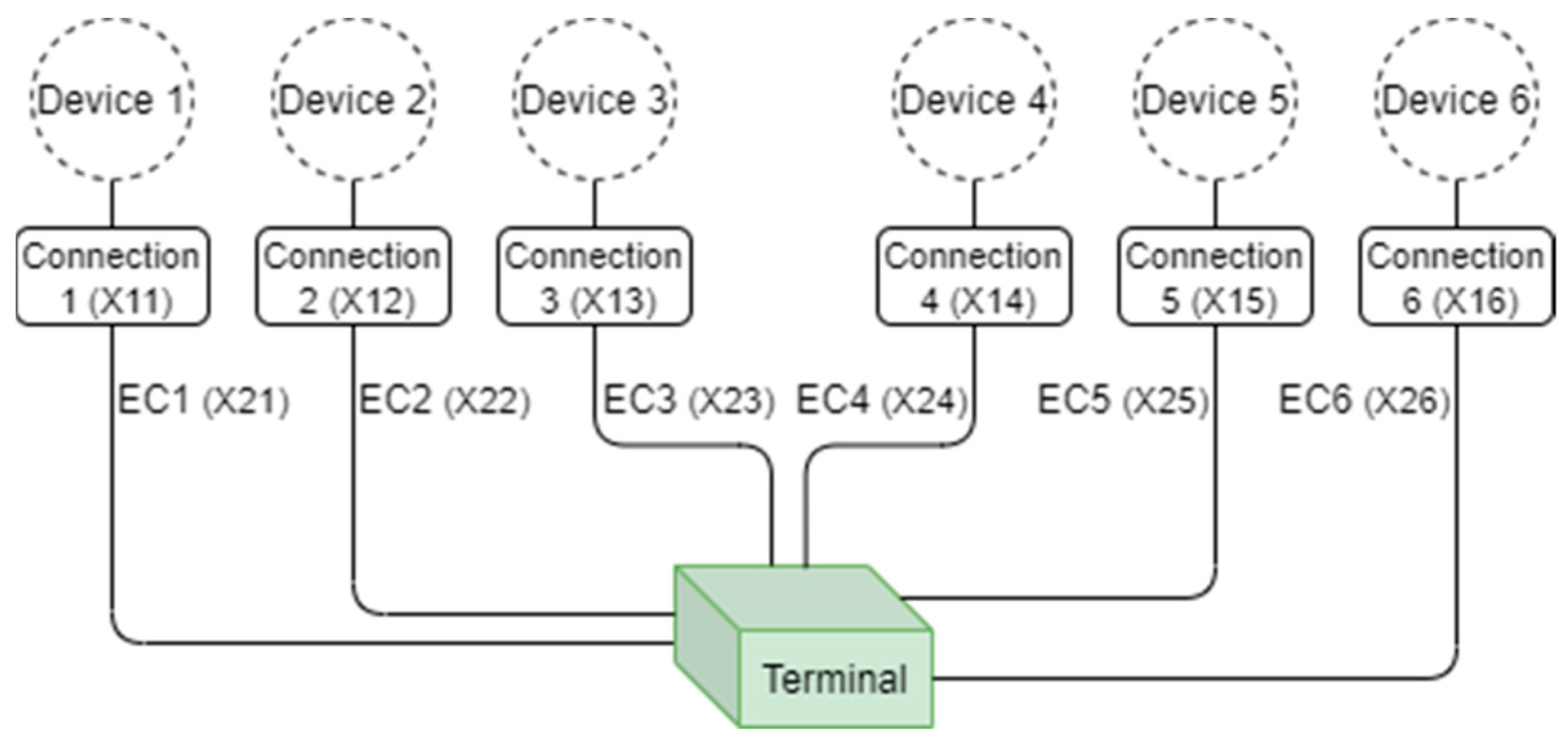
The typical energy delivery network topologies are three typical design solutions in an EU-sponsored project, i.e., DTOceanPlus. This project aims to design tools for the selection, development, deployment and assessment of ocean energy systems. Three typical energy delivery network topologies refer to Radial, Star and Direct [10]. Graphical examples of these energy delivery network topologies are shown in Figure 2, Figure 3 and Figure 4, respectively. The symbols in the brackets represent the labels of the nodes in the BN models.
The notations in Figure 2, Figure 3 and Figure 4 are explained as follows:
  • “AC” represents array cable;
  • “Connection” represents either: a connector in the case of a fixed device or an umbilical and its connectors for floating devices;
  • “CP” represents the collection point. There are six devices in these network topologies for the demonstration purpose;
  • “EC” represents the export cable.
A connection refers to a connector connecting an array cable and a device (or called marine energy converter). An array cable refers to a cable connecting different devices or a device and a connection point. An export cable refers to a cable transmitting the power from an array to the on-shore terminal.
A collection point acts as a hub or a substation, or both. Each collection point could be a switchgear, transformer, or power quality/conditioning equipment. Two typical collection point solutions may be on the free water surface or mounted on the seabed.

3. Bayesian Network Formulation

This section mainly describes the key aspects for assessing the availability using Bayesian networks, with the focus on improvements of the BN models compared to that used in [12]. The key aspects include:
  • Bayesian network structure for the system: Calculate the current availability of the system given the current state of the basic components;
  • Dynamic Bayesian network for calculation of time-dependent availability;
  • Implementing repairs through decision rules.

3.1. Bayesian Network Structure for the System

The aim of this step is to establish a logic Bayesian network model for the calculation of the system availability based on the current state of the basic components. The logic dependencies of the units identified through qualitative system analysis can provide enough information to establish this part of the BN model. A logic gate in the hierarchy can be represented by a conditional probability table in the BN model. In most engineering applications, the ‘gate’ can be either ‘OR’, ‘AND’ or ‘k/N’ (also called vote gate in some textbooks). With no loss of generality, the nodes underneath the gate are called input, and the node above it is called output. ‘OR’ means that if any input to the gate fails, the output fails. ‘AND’ means that if all the inputs to the gate fail, the output fails. ‘k/N’ means that if either k out of N inputs fail, the output fails. Here we will exploit the logic relations to estimate the availability.
The system availability is 100% if energy from all N devices in the system is transmitted to the terminal; if energy from n components is transmitted, the availability is n/N. In Figure 2, Figure 3 and Figure 4, the relations between the basic components in the systems are illustrated. All nodes for basic components have two states: 0—faulty, or 1—healthy. The system availability is calculated based on the node T0 which have N + 1 states, and indicates the number of devices for which energy is transmitted to the terminal. To establish a Bayesian network for assessment of the system availability, it is convenient to define sub-assemblies. For sub-assemblies, the state correspond to the number of devices for which energy is transmitted. For example, a sub-assembly with three connected devices have four possible states: 0, 1, 2, 3, as defined in Table 1. The Bayesian network structure is defined in terms of the hierarchy of the nodes. As an example we will consider a simple structure with three basic components, X1, X2 and X3. X1 and X2 both have a device connected. They are connected in parallel, and together they form the sub-assembly T1. This corresponds to an ‘AND’ gate. For AND gates, the number of working devices of the parents are added together to get the number of working units. Sub-assembly T1 and component X3 are connected in series, which correspond to an ‘OR’ gate. For OR gates, the number of working units of the child is zero if it is zero for any of the parents.
In Section 4, the actual hierarchies will be shown.

3.2. Dynamic Bayesian Network Models

With the aim of investigating the time-dependent availability, the dynamic BN model will be used in this study. The concept, time slice, should be introduced. The continuous design lifetime is split into some discretized time intervals for which the probabilities of different states of the energy delivery network topology are assessed. Each of these time intervals is called a time slice, which could refer to 1 day, 1 week, 1 month, 1 year, etc.

3.2.1. Conditional Probability Tables

In this section, how to define temporal condition probabilities will be presented. Initially, all the basic components are in healthy state, which means the state of the temporal clone of the nodes representing the basic components is 1.
The temporal conditional probabilities depend upon the state of the energy delivery network in the previous time slice and the pre-chosen decision rule. With the aim of taking into account these effects, a temporal clone of the node representing the energy delivery network and a node representing the repair option should be created. The node representing the repair option has two states, namely ‘0’—no repair; or ‘1’—repair. The state of the node representing the repair option depends upon the state of the energy delivery network in the previous time slice.
With no loss of generality, a single basic component, R1, is used to demonstrate how to define the temporal conditional probabilities. The time to failure (TTF) of the basic component k is assumed to follow the exponential distribution, with a constant failure rate of λ k .   t denotes the time interval between two time slices. The subscripts i and i + 1 represent two consecutive time slices.
If no repair is required between two consecutive time slices, the conditional probabilities are given as follows:
P ( R 1 = 0 ;   t = t i + 1 | R 1 = 0 ;   t = t i ) = 1 ,
P ( R 1 = 1 ;   t = t i + 1 | R 1 = 0 ;   t = t i ) = 0 ,
P ( R 1 = 0 ;   t = t i + 1 | R 1 = 1 ;   t = t i ) = 1 e λ k t ,
P ( R 1 = 1 ;   t = t i + 1 | R 1 = 1 ;   t = t i ) = e λ k t ,
If repair is required between two consecutive time slices, the conditional probabilities are given as follows:
P ( R 1 = 0 ;   t = t i + 1 | R 1 = 0 ;   t = t i ) = 0 ,
P ( R 1 = 1 ;   t = t i + 1 | R 1 = 0 ;   t = t i ) = 1 ,
P ( R 1 = 0 ;   t = t i + 1 | R 1 = 1 ;   t = t i ) = 1 e λ k t ,
P ( R 1 = 1 ;   t = t i + 1 | R 1 = 1 ;   t = t i ) = e λ k t ,
The decision rules can be implemented through a repair node in the BN model. This repair node is a child of the node representing the energy delivery network. The state of this system node in time slice i determines that of the repair node in time slice i + 1. See Supplementary Materials for the CPTs of the repair node.

3.2.2. Decision Rules

For the energy transfer subsystem composed of M converters, the decision rules can be defined from the perspective of effective energy production. A decision rule pre-defines which maintenance activities should be taken when a certain amount of devices shut down.
It is assumed that there is a threshold ratio of the full energy production, k. A maintenance team should be dispatched to repair the damaged components when the monitored energy production is less than k% of the full energy production. Figure 5 demonstrates which activity should be done in which decision rule for which failure scenario. For example, it is required in Decision Rule 2 that if two out of M devices malfunction, namely the energy loss is (200/M)%, the damaged components causing such an energy loss should be repaired as soon as possible.

4. Case Study

4.1. Network Topologies

Three typical energy delivery network topologies in the project DTOceanPlus, with the sketches shown in Figure 2, Figure 3 and Figure 4, are used for this case study. Due to no tailor-made reliability database for marine energy converters, the failure rates of the basic components can be referred to a generic database for electrical components in other industrial applications [13,14] and also should be subject to engineering judgement. The failure rates to be used are given in Table 2.

4.2. Logic Dependencies of the Topologies

The logic dependencies are defined in a table-like data format. The advantages are:
  • the system structure and the interrelationship between units at different level can be clearly represented without a long description.
  • such a data structure is self-explanatory and can be easily implemented in computer code.
Besides the table-formatted hierarchy, the interrelationship between units on the top-most level in the hierarchy will be briefly interpreted with text for each topology in the following sub-sections.
The hierarchies of the Radial, Star, and Direct topology are defined in Table 3, Table 4 and Table 5 respectively. The top event is denoted ‘Failure of ED System (T0)’. For the Radial topology, the intermediate failure events underneath the top event refer to ‘X19’, ‘X21’, ‘X20’ and ‘Failure of T1’. An ‘OR’ gate is inserted, because if either of them fails, T0 fails. For the Star topology, the intermediate failure events underneath the top event refer to ‘X19’, ‘X20’, ‘X23’ and ‘Failure of T1’, and here an ‘OR’ gate is also used. For the Direct topology, the intermediate failure events underneath the top event refer to ‘Failure of T1’~‘Failure of T6’. The working philosophy indicates that: if and only if T1~T6 fail, T0 fails. Therefore, an ‘AND’ is inserted.

4.3. Bayesian Network Models

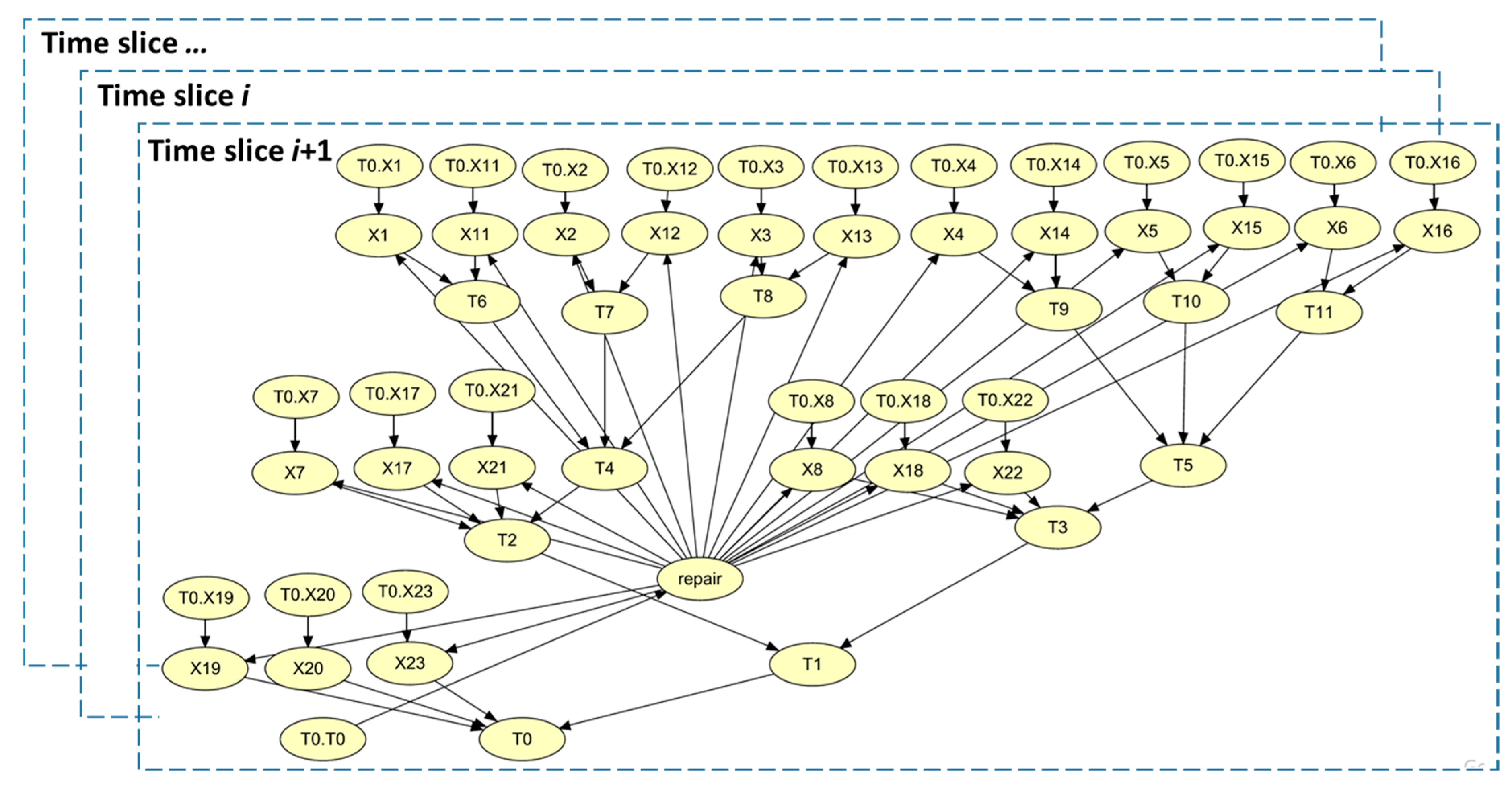
Hugin Expert [15], used for Bayesian inference, provides an independent interface for Python to construct the BN models, which is more efficient than manual operations of drawing BNs in the Hugin graphical user interface. The dynamic BN models of the three energy delivery network topologies are shown in Figure 6, Figure 7 and Figure 8, respectively. The arrows pointing from nodes in time slice i to the same nodes in time slice i + 1 should be drawn to explicitly represent the temporal dependencies. However, due to a large number of nodes, the readability will be unfavourably affected if too many arrows are shown on the same figure. Therefore, three overlapped boxes approximately represent the temporal dependencies. The implicit temporal clones of the nodes corresponding to the basic components can be represented by Ti.xx. “Ti” indicates the time slice i, and “xx” is the node label. In Figure 6, Figure 7 and Figure 8, the initial temporal clones of nodes are only shown (the prefix, “T0” in front of the nodes corresponding to the basic components). The T0 in “T0.xx” is a symbol representing the initial time slice. It should be differentiated from the node T0 representing the energy delivery system.
The criterion for choosing a time interval between slices should depend upon the actual maintenance interval adopted by the owners. As mentioned in Section 1, the marine energy industry is still at a pre-mature stage. However, the operating experience of the wind industry can be borrowed. Generally, wind turbine owners have both long-term and short-term maintenance plans. The short-term maintenance is usually planned on a monthly basis. Therefore, the time interval between slices is one month. With consideration of a 20-year design lifetime, there are 240 time slices in the dynamic BN model.

4.4. Calculation of Time-Dependent Availability

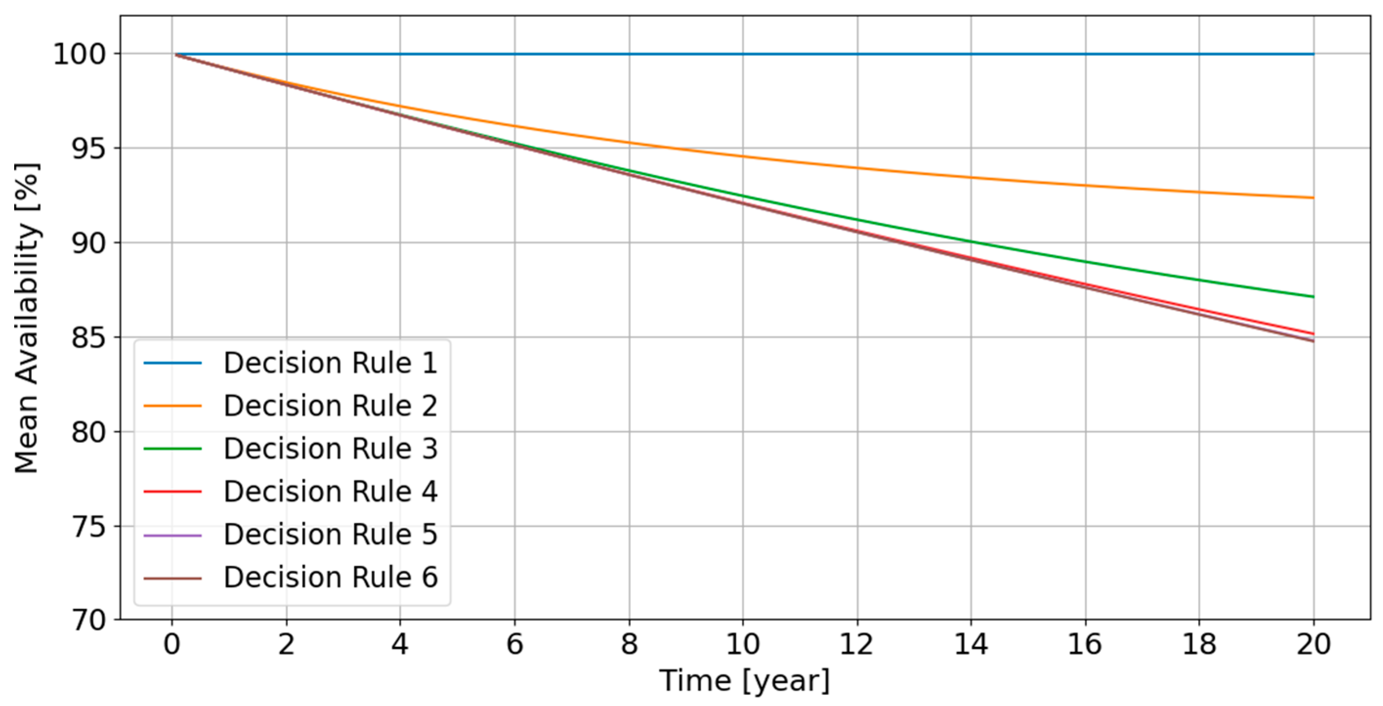
Based upon the improved BN models, the time-dependent availability has been calculated for the three network topologies (see Figure 9, Figure 10 and Figure 11). The computational time can be significantly shortened if the improved BN model is used. For the direct and radial network topologies, it only takes around 20 s to obtain the results for all time slices. For the star topology, it takes about 15 min. The original method in [12] took about 1 h for 1000 simulations.
The generic trend shown in these figures is:
  • The availability remains close to 100% (greater than 99%) if Decision rule 1 is chosen; this agrees with the engineering prediction, because Decision rule 1 indicates that repair must be done immediately if any basic component fails; the energy delivery network is almost always in a fully rated state and the system availability should remain close to 100%.
  • For the decision rules other than Decision rule 1, the mean availability decreases with decreasing rate, thus stabilizing over long time. For Decision rules 2 and 3, there is no significant difference in the system availability between these topologies.
  • For Decision rules 5 and 6, where more energy losses can be allowed, the availability is relatively low, because these decision rules exactly or almost correspond to a corrective maintenance strategy, respectively.
It can be observed from Figure 9 and Figure 10 that:
  • For Decision rules 2 and 3, the decrease rate becomes slow after around Year 14. This indicates that these decision rules can ensure that the mean system availability stabilizes around a relatively high value in the long term.
  • For the other decision rules, the availability decreases significantly over the design lifetime. A higher number of damaged basic components is allowed, which will definitely lower down the expected system availability.
It can be observed from Figure 11 that:
  • The Direct topology leads to higher mean availabilities for decision rules 4–6. This makes sense because the Direct topology resembles a parallel system, while Radial and Star topologies are more like a series of parallel systems; if more components are allowed to fail without repair, the parallel system should be able to work at a derated energy delivery level.
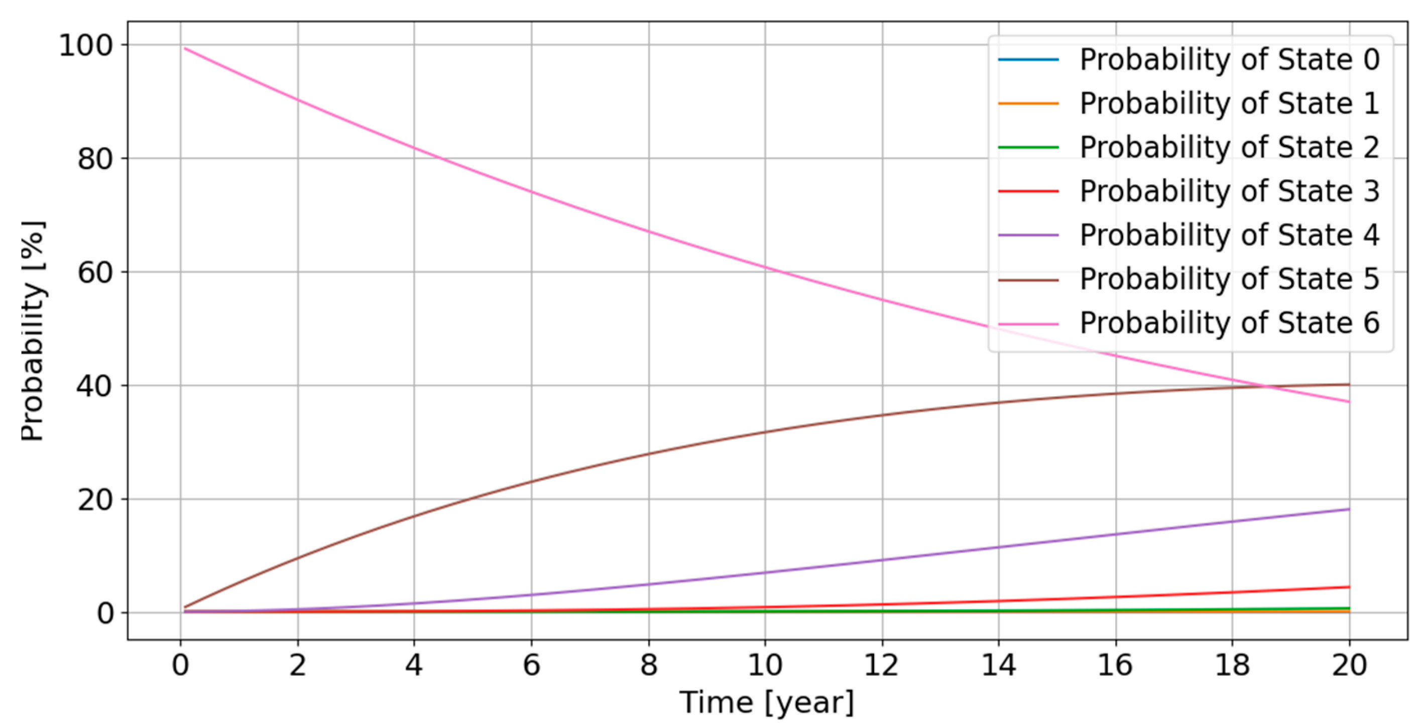
In the BN model, the probabilities of different states of the node T0 representing the system are calculated at each time slice. Take Decision Rule 6 for Direct topology as an example. The probabilities of different states as a function of time are shown in Figure 12.
From the perspective of engineering design, the predicted availability of an optimal energy delivery network should exhibit a high robustness and redundancy. Basically, Direct topology gives relatively higher availability when more basic components fail (corresponding to Decision rules 4–6).

5. Conclusions

The improved BN model in this study can more efficiently calculate the time-dependent availability than the method used in [12]. The significant decrease in computational time is due to no Monte Carlo simulation of time to failure of basic components and no need to search the fault tree to determine when maintenance has to be done according the pre-chosen decision rule. Instead, a two-state repair node (state 0—no repair; or state 1—repair) is added to determine if a repair is needed in the current time slice, based upon the state of the system node (T0) in the previous time slice.
The decision rules covering both different maintenance strategies are directly implemented in the BN model by defining the relevant CPTs of the repair node. The BN model can automatically take into account the effect of maintenance strategies on the probabilities of different availability states, then predict the time-dependent availability.
From the perspective of energy delivery efficiency and robustness, the Direct topology is optimal to give the highest availability. Based upon this improved model, future works can include:
  • the maintenance costs (OPEX costs) can be estimated by adding relevant nodes in the BN model;
  • with the combination of CAPEX and OPEX costs, the optimal design solution to the energy delivery network can be finally determined.
It should be noted that some factors affecting the maintenance costs, for example the weather window and logistic-related issues (the availability of technicians, vessels and spare parts), are not considered in this study. These factors can be integrated in the updated BN model in the future research work.

Supplementary Materials

The conditional probability tables for all the nodes are defined for all the network topologies. The following are available online at https://www.mdpi.com/article/10.3390/en14123574/s1, Table S1: Radial topology, Table S2: Star topology, Table S3: Direct topology, Table S4: CPTs for the repair node.

Author Contributions

J.S.N. proposed the idea of the improved Bayesian Network model. Y.Y. implemented it in Python and Hugin Expert. All authors have read and agreed to the published version of the manuscript.

Funding

The research is financially supported by the DTOceanPlus project.

Institutional Review Board Statement

Not applicable.

Informed Consent Statement

Informed consent was obtained from all subjects involved in the study.

Data Availability Statement

Not applicable.

Acknowledgments

This work has been partially supported by European Union’s Horizon 2020 research and innovation programme under grant agreement No 785921, project DTOceanPlus (Advanced Design Tools for Ocean Energy Systems Innovation, Development and Deployment).

Conflicts of Interest

The authors declare that there is no conflict of interest.

References

  1. Melikoglu, M. Current Status and Future of Ocean Energy Sources: A global review. Ocean Eng. 2018, 148, 563–573. [Google Scholar] [CrossRef]
  2. Alamiana, R.; Shafaghat, R.; Shadloo, M.S.; Bayani, R.; Amouei, A.H. An Empirical Evaluation of The Sea Depth Effects for Various Wave characteristics on The Performance of a Point Absorber Wave Energy Converter. Ocean Eng. 2017, 137, 13–21. [Google Scholar] [CrossRef]
  3. Mustapa, M.; Yaakob, O.; Ahmed, Y.M.; Rheem, C.-K.; Koh, K.; Adnan, F.A. Wave Energy Device and Breakwater Integration: A Review. Renew. Sustain. Energy Rev. 2017, 77, 43–58. [Google Scholar] [CrossRef]
  4. Falcao, A.D.d.O. Wave Energy Utilization: A Review of The Technologies. Renew. Sustain. Energy Rev. 2010, 14, 899–918. [Google Scholar] [CrossRef]
  5. Aderino, T.; Li, H. Ocean Wave Energy Converters: Status and Challenges. Energies 2018, 11, 1–26. [Google Scholar]
  6. IEC. IEC TS 62600-2 ED2 Marine Energy—Wave, Tidal and Other Water Current Converters—Part 2: Design Requirements for Marine Energy Systems; IEC: Geneva, Switzerland, 2018. [Google Scholar]
  7. Rinaldi, G.; Thies, P.R.; Walker, R.; Johanning, L. A Decision Support Model to Optimise the Operation and Maintenance Strategies of An Offshore Renewable Energy Farm. Ocean Eng. 2017, 145, 250–262. [Google Scholar] [CrossRef]
  8. Rinaldi, G.; Portillo, J.C.C.; Khalid, F.; Henriques, J.C.C.; Thies, P.R.; Gato, L.M.C.; Johanning, L. Multivariate Analysis of the Reliability, Availability, and Maintainability Characterizations of a Spar-buoy Wave Energy Converter Farm. J. Ocean Eng. Mar. Energy 2018, 4, 199–215. [Google Scholar] [CrossRef] [Green Version]
  9. Mason, A.; Driver, R.; Hay, S.; Hodges, R. Marine Energy Electrical Report 3: Optimum Electrical Array Architectures PN000083-LRT-008; CATAPULT Offshore Renewable Energy: Glasgow, UK, 2015. [Google Scholar]
  10. Noble, D.R.; Nambiar, A. DTOceanPlus—Advanced Design Tools for Ocean Energy Systems Innovation, Development and Deployment Deliverable D5.5—Alpha Version; The University of Edinburgh: Edinburgh, UK, 2020. [Google Scholar]
  11. Sharkey, F. Offshore Electrical Networks and Grid Integration of Wave Energy Converter Arrays—Techno-Economic Optimisation of Array Electrical Networks, Power Quality Assessment and Irisk Market Perspectives; Technological University Dublin: Dublin, Ireland, 2015. [Google Scholar]
  12. Yang, Y.; Sørensen, J.D. Probabilistic Availability Analysis for Marine Energy Transfer Subsystem Using Bayesian Network. Energies 2020, 13, 5108. [Google Scholar] [CrossRef]
  13. Department of Denfense. Military Handbook—Reliability Prediction of Electronic Equipment MIL-HDBK-217F; Department of Denfense: Washington, DC, USA, 1991. [Google Scholar]
  14. Walnock, J.; McMillan, D.; Pilgrim, J.; Shenton, S. Failure Rates of Offshore Wind Transmission Systems. Energies 2019, 12, 1–12. [Google Scholar]
  15. Hugin Expert A/S. Hugin API Reference Manual; Hugin Expert A/S: Aalborg, Denmark, 2018. [Google Scholar]
Figure 1. Break-down of the Marine Energy Conversion System.
Energies 14 03574 g001
Figure 2. Schematic Illustration of Radial Topology.
Energies 14 03574 g002
Figure 3. Schematic Illustration of Star Topology.
Energies 14 03574 g003
Figure 4. Schematic Illustration of Direct Topology.
Energies 14 03574 g004
Figure 5. The Analysis Flowchart with Decision Rules Considered.
Energies 14 03574 g005
Figure 6. Bayesian Network Model for Radial Topology.
Energies 14 03574 g006
Figure 7. Bayesian Network Model for Star Topology.
Energies 14 03574 g007
Figure 8. Bayesian Network Model for Direct Topology.
Energies 14 03574 g008
Figure 9. Mean Availability for Six Decision Rules–Radial Topology.
Energies 14 03574 g009
Figure 10. Mean Availability for Six Decision Rules–Star Topology.
Energies 14 03574 g010
Figure 11. Mean Availability for Six Decision Rules–Direct Topology.
Energies 14 03574 g011
Figure 12. Example of Probability Distribution of Different States (Decision Rule 6; Direct Topology).
Energies 14 03574 g012
Table 1. A Template of Hierarchy.
UnitTypeChild NodesParent NodesRelationStates
T0SystemN.A.[T1, X3]‘OR’[0, 1, 2]
T1Sub-assemblyT0[X1, X2]‘AND’[0, 1, 2]
X1Basic ComponentT1N.A.N.A.[0, 1]
X2Basic ComponentT1N.A.N.A.[0, 1]
X3Basic ComponentT0N.A.N.A.[0, 1]
Table 2. Failure Rates of Basic Components.
ItemLabels in SketchValue [1/Hour]
Array cable AC3.31 × 10−7
Export cableEC3.31 × 10−7
ConnectionConnector6.24 × 10−7
CPCP9.83 × 10−7
Table 3. Hierarchy of Radial Topology.
UnitTypeChild NodesParent NodesRelation
T0SystemN.A.[X19, X20, X21, T1]OR
T11st-level sub-assemblyT0[T2, T3]AND
T22nd-level sub-assemblyT1[X17, X3, T4]OR
T32nd-level sub-assemblyT1[X18, X6, T5]OR
T43rd-level sub-assemblyT2[X13, X2, T6]2/3
T53rd-level sub-assemblyT3[X16, X5, T7]2/3
T64th-level sub-assemblyT4[X12, T8]OR
T74th-level sub-assemblyT5[X15, T9]OR
T85th-level sub-assemblyT6[X11, X1]OR
T95th-level sub-assemblyT6[X14, X4]OR
X11Basic Component (Device)T8N.A.N.A.
X12Basic Component (Device)T6N.A.N.A.
X13Basic Component (Device)T4N.A.N.A.
X14Basic Component (Device)T9N.A.N.A.
X15Basic Component (Device)T7N.A.N.A.
X16Basic Component (Device)T5N.A.N.A.
X17Basic ComponentT2N.A.N.A.
X18Basic ComponentT3N.A.N.A.
X19Basic ComponentT0N.A.N.A.
X1Basic ComponentT8N.A.N.A.
X2Basic ComponentT4N.A.N.A.
X3Basic ComponentT2N.A.N.A.
X4Basic ComponentT9N.A.N.A.
X5Basic ComponentT5N.A.N.A.
X6Basic ComponentT2N.A.N.A.
X20Basic ComponentT0N.A.N.A.
X21Basic ComponentT0N.A.N.A.
Table 4. Hierarchy of Star topology.
UnitTypeChild NodesParent NodesRelation
T0SystemN.A.[X19, X20, X23, T1]OR
T11st-level sub-assemblyT0[T2, T3]AND
T22nd-level sub-assemblyT1[X7, X17, X21, T4]OR
T32nd-level sub-assemblyT1[X8, X18, X22, T5]OR
T42nd-level sub-assemblyT2[T6, T7, T8]AND
T52nd-level sub-assemblyT3[T9, T10, T11]AND
T63rd-level sub-assemblyT4[X1, X11]OR
T73rd-level sub-assemblyT4[X2, X12]OR
T83rd-level sub-assemblyT4[X3, X13]OR
T93rd-level sub-assemblyT5[X4, X14]OR
T103rd-level sub-assemblyT5[X5, X15]OR
T113rd-level sub-assemblyT5[X6, X16]OR
X1Basic ComponentT6N.A.N.A.
X2Basic ComponentT7N.A.N.A.
X3Basic ComponentT8N.A.N.A.
X4Basic ComponentT9N.A.N.A.
X5Basic ComponentT10N.A.N.A.
X6Basic ComponentT11N.A.N.A.
X7Basic ComponentT2N.A.N.A.
X8Basic ComponentT3N.A.N.A.
X11Basic Component (Device)T6N.A.N.A.
X12Basic Component (Device)T7N.A.N.A.
X13Basic Component (Device)T8N.A.N.A.
X14Basic Component (Device)T9N.A.N.A.
X15Basic Component (Device)T10N.A.N.A.
X16Basic Component (Device)T11N.A.N.A.
X17Basic ComponentT2N.A.N.A.
X18Basic ComponentT3N.A.N.A.
X19Basic ComponentT0N.A.N.A.
X20Basic ComponentT0N.A.N.A.
X21Basic ComponentT2N.A.N.A.
X22Basic ComponentT3N.A.N.A.
X23Basic ComponentT0N.A.N.A.
Table 5. Hierarchy of Direct Topology.
UnitTypeChild NodesParent NodesRelation
T0SystemN.A.[T1, T2, T3, T4, T5, T6]AND
T11st-level sub-assemblyT0[X11, X21]OR
T21st-level sub-assemblyT0[X12, X22]OR
T31st-level sub-assemblyT0[X13, X23]OR
T41st-level sub-assemblyT0[X14, X24]OR
T51st-level sub-assemblyT0[X15, X25]OR
T61st-level sub-assemblyT0[X16, X26]OR
X11Basic Component (Device)T1N.A.N.A.
X12Basic Component (Device)T2N.A.N.A.
X13Basic Component (Device)T3N.A.N.A.
X14Basic Component (Device)T4N.A.N.A.
X15Basic Component (Device)T5N.A.N.A.
X16Basic Component (Device)T6N.A.N.A.
X21Basic ComponentT1N.A.N.A.
X22Basic ComponentT2N.A.N.A.
X23Basic ComponentT3N.A.N.A.
X24Basic ComponentT4N.A.N.A.
X25Basic ComponentT5N.A.N.A.
X26Basic ComponentT6N.A.N.A.
Publisher’s Note: MDPI stays neutral with regard to jurisdictional claims in published maps and institutional affiliations.