Article

Integrated Offshore Seismic Survey Using an Unmanned Wave Glider

1
Korea Institute of Geoscience and Mineral Resources, 124, Gwahak-ro, Yuseong-gu, Daejeon 34132, Korea
2
Ocean Tech, 214, Haengjusanseong-ro, Deogyang-gu, Goyang-si, Gyeonggi-do 10440, Korea
*
Author to whom correspondence should be addressed.
Energies 2021, 14(2), 297; https://doi.org/10.3390/en14020297
Submission received: 13 October 2020 / Revised: 14 December 2020 / Accepted: 4 January 2021 / Published: 7 January 2021
(This article belongs to the Special Issue Marine Renewable Energy Technology)

Abstract

:
An autonomous surface vehicle, known as a wave glider, was used to record refracted and reflected signals from a seismic source penetrating the shallow subsurface. An integrated survey system consisting of a wave gilder and a human-operated source vessel was deployed. These survey systems are used to acquire wide-offset seismic survey data from specific areas, such as offshore structures. The wave gliders can collect seismic refraction and reflection data, which can be used to estimate subsurface information, e.g., acoustic wave velocity and subsurface structure. We processed raw data collected by a receiver equipped with the wave glider and used the relationship between travel time and offset distance to calculate the velocities of shallow sedimentary deposits and the acoustic basement. The velocities of the sedimentary deposits and basement were estimated to be 1557 and 3507 m/s, respectively. We then overlaid the velocities on subsurface data measured using a single-channel streamer. Our results indicate that unmanned equipment can be used for ocean exploration to aid offshore energy development.

1. Introduction

Remotely operated vehicles (ROVs) and autonomous underwater vehicles (AUVs) are increasingly being used in geoscience studies to make direct observations and to obtain ultra-high-resolution mapping data [1]. ROVs equipped with robotic manipulators have been used to obtain real-time images, geochemical samples, and sediment cores [2,3]. AUVs mounted with various geophysical acquisition systems, such as multi-beam echo sounders (MBESs), side-scan sonar (SSS), and sub-bottom profilers (SBPs), have provided three-dimensional bathymetric maps and sub-bottom seismic volumes with decimeter resolutions [3,4]. AUVs without umbilical cables have conducted seafloor mapping under glaciers [5]. However, the sensors used for seafloor mapping consume considerable electric power, thereby limiting survey time.
Autonomous underwater gliders (AUGs) are equipped with passive sensors (e.g., for temperature, conductivity, and passive acoustics) and move via buoyancy control, so they can be used for oceanographic observations over large areas for long periods of time [6]. The wave glider (WG; Figure 1a) manufactured by Liquid Robotics is an unmanned surface vehicle (USV) that is distinct from other AUGs because it produces its own power via solar panels and wave motion [7]. WGs acquire scientific data such as temperature, salinity, and seawater current [7]. Recent applications are focused more on scientific and engineering fields [5,6]. Taking advantage of the WG’s versatility, we performed an integrated engineering-scale seismic survey (Figure 1b).
Engineering-scale seismic surveys collect geophysical information from seawater and beneath the subsurface to aid offshore energy development (e.g., wind, wave, tidal, or thermal energy) [8,9]. Identifying unconsolidated sedimentary deposits and the acoustic basement is particularly crucial to offshore engineering surveys [10,11]. Surveys can be hampered by limited illumination of deep targets and interference by obstacles in the environment [12,13,14]. Such limitations can impact survey quality and can be overcome using a wide azimuth seismic (WAS) geometric configuration, which enlarges the offset distance between the source and receiver of seismic wave propagation [14,15]. WAS is an uppermost interest in geotechniques that accompany long-offset streamers, ocean bottom nodes (OBNs), and/or maneuvering of additional vessels [14]. Unmanned equipment can improve the cost efficiency of WAS in offshore surveys and has provided excellent results for reservoir-scale seismic surveys [16,17]. Although WAS coupled with autonomous surface vehicles is a promising method for conducting offshore surveys, some issues remain [16].
Small-scale engineering surveys with WGs can improve offshore seismic surveys using accurate receiver positioning, large volumes of continuously recorded data, and endurance against strong currents. Reservoir-scale seismic surveys primarily require reflected signals to record the source-to-receiver time (with various offsets) in addition to refracted signals with specific time signatures. Engineering-scale seismic surveys require refracted signals, which contain travel time information [18,19]. The travel times of seismic traces and distance offsets are related to subsurface velocity. Here, we used refraction signal data to calculate sedimentary deposits and basement velocity. Velocities were overlain with a seismic section recorded by a single-channel streamer that collected reflected signals. The integration of refraction and reflection data enabled subsurface properties (e.g., velocity) to be extended to subsurface images (e.g., structure) in the spatial domain.
The purpose of this study was to develop an easy and efficient shallow offshore WAS (1) by configuring an integrated survey system with a WG and (2) by deriving the velocity value of the shallow sedimentary deposits. To this end, we undertook configurations using trigger synchronization and real-time quality control and conducted a field test at Achi Island in Busan Bay, Korea. The velocities of shallow sedimentary deposits were calculated from the relationship between travel time and offset distance. Our system has unique features of active triggers, and integration between the WG and single channel streamer, so that the integrated survey system can be used for shallow WAS surveying and offshore energy development.

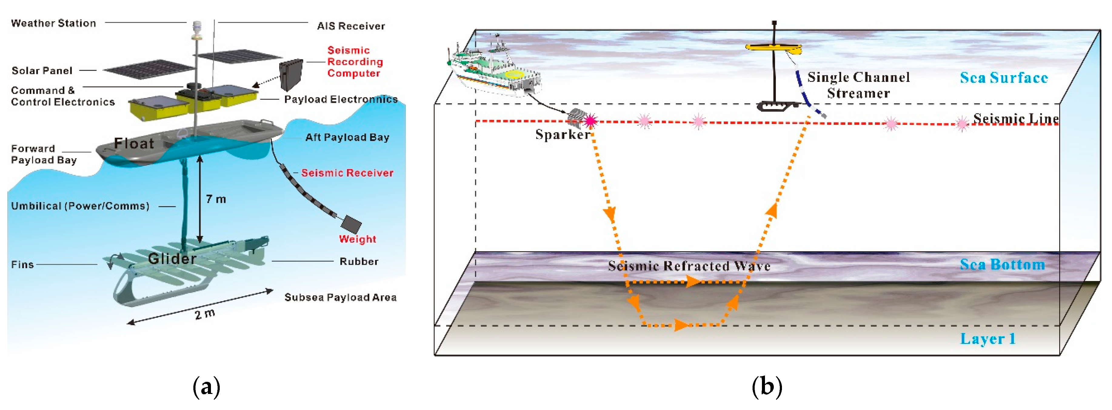
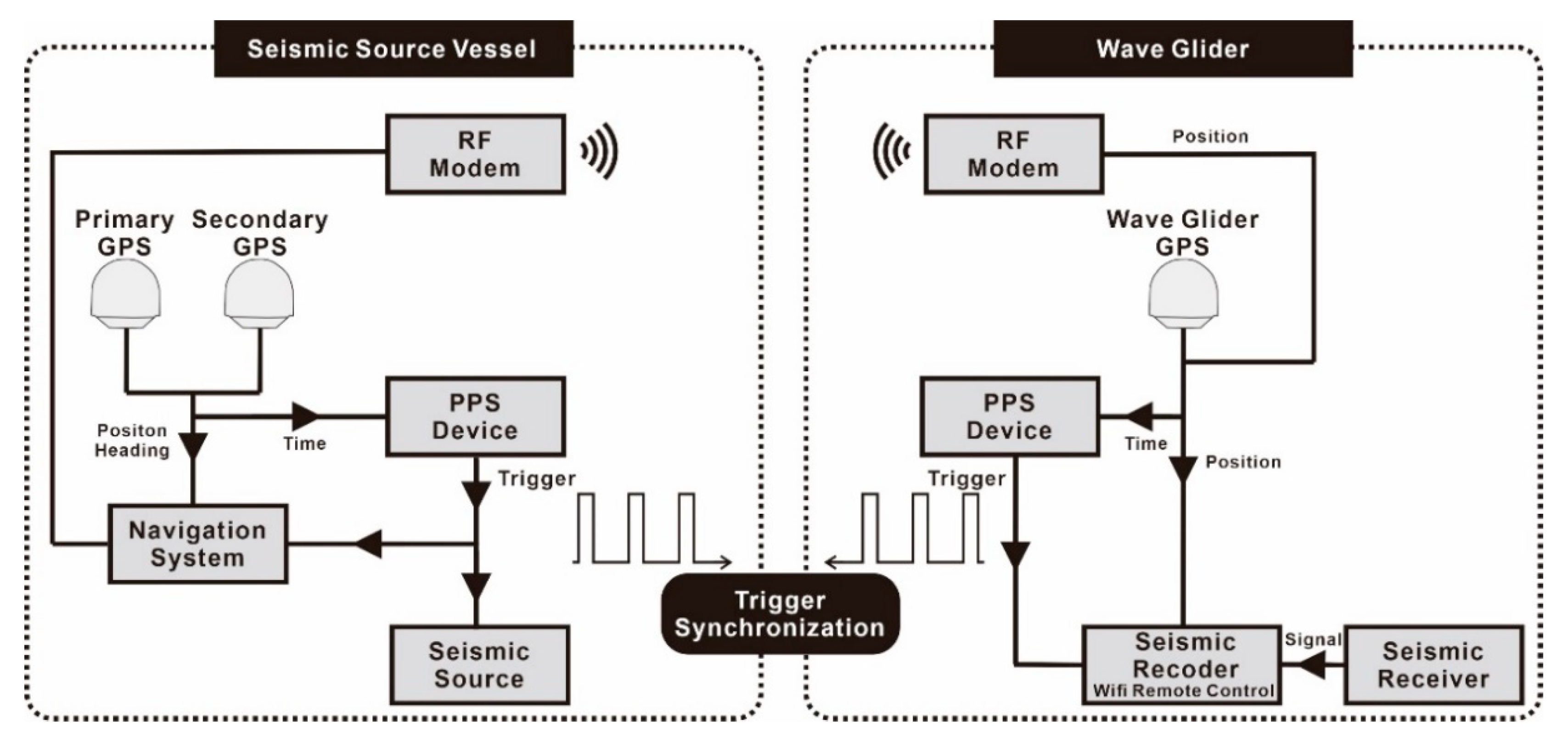
2. Configuration of the Wave Glider and Seismic Survey

We used a SV2 Wave Glider (Liquid Robotics, Sunnyvale, CA, USA; specifications described in Table 1). The WG has station-keeping functionality that operates within a 40-m radius for maintaining water speeds of 0.8–1.0 m/s against the swell and waves. The communication software included in the WG uses the global positioning system (GPS), allowing it to be controlled and monitored via a webpage. The WG’s integrated survey system can replace the seismic signal-receiver functionality of radio sonobuoys, which are obsolescent survey recorders frequently used in offshore refraction surveys [20]. Here, the WG was placed on a pre-plotted seismic line, and we used a sparker towed by the survey vessel to shoot sound pulses at the seismic source at constant intervals (Figure 1b). Data were acquired with a single-channel streamer (10 elements spaced 0.3 m apart) mounted on the WG and recorded by a desktop computer using seismic acquisition software (Figure 1a).
Because the seismic source and recording system were operated separately, we had to address issues related to trigger synchronization between the two systems, to the parameter settings of the data acquisition software, and to data quality control (QC). To solve the trigger synchronization problem, we employed pulse-per-second (PPS) time synchronization using a GPS. This was possible because the shot mode used a constant time interval. During the production mode, the time interval cannot be changed. To access the recording system on the desktop computer, we used a radio frequency (RF) modem, which can be used only in coastal areas where mobile phone communications are available. Because the connection distance was limited, it functioned only when the distance between the WG and the source vessel was within a 1.5-km range. Furthermore, it is dependent on the communication conditions. Figure 2 shows a schematic diagram of the data acquisition configuration used in this study.
In this study, conventional equipment was used (Figure 1a). The WG had a GPS antenna for positioning, a single channel streamer for recording, and a glider body for sailing. The WG can be operated for missions lasting over 2 h. To record refracted and reflected seismic signals from the subsurface, we maneuvered the source vessel along a pre-plotted line. We used a sparker (manufactured by Services and Instruments of Geophysique; SIG) to generate high-frequency (dominant frequency bandwidth of 200–400 Hz) electrical signals [21]. The control vessel speed was maintained at 3.5 knots to ensure stable shot intervals (Figure 1b). Active position-keeping reduced the static error caused by the current.
Communication between the WG and source vessel was accomplished via an RF modem. The data acquisition system records seismic signals using a single-channel streamer to produce two-dimensional (2D) sections. We synchronized the trigger time between the source vessel and WG at each shot (Figure 2). This configuration was intended to simply confirm the feasibility of this seismic survey system for use in future larger-scale surveys.

3. Field Survey and Seismic Data

To validate the system in the field, we conducted a test survey in Busan Bay, South Korea over 5 days (21–25 June 2016).

3.1. Study Area

The study area was selected based on criteria to guarantee data quality and stable acquisition conditions: (i) availability of cellular communications to provide a connection between the WG and source vessel, (ii) water depth range of 10–30 m due to the 7 m-long umbilical cable of the WG, (iii) flat seafloor topography to ensure the velocity of the first layer was as simple as possible, (iv) horizontally distributed sedimentary strata structures with constant thickness, and (v) flatly distributed acoustic basement to easily and simply distinguish the refracted events for the layers.
The survey area in this study was located near Archi Island (at Korea Maritime and Ocean University) in Yeongdo, Busan Bay (Figure 3a). Because this site is adjacent to a coastal area, cellular communications are guaranteed. The water depth ranges from 10 to 20 m on the marine chart (Figure 3a). Since it is a sea lane, the seafloor topography is flat by dredging. In addition, previous studies [10,22,23] conducted on various shallow marine seismic data acquisition systems’ development and field tests showed the simple sedimentary strata structures interpreted by a sub-bottom layer and an acoustic basement.
The area features offshore constructions, including a cruise ship pier and concrete breakwater. The water depth is approximately 20 m, and the seafloor topography has been flattened via dredging to accommodate seaways and the nearby Busan City port. The seafloor is clearly divided into two layers [21,24]. The port has a high volume of cargo traffic and fishing ships and is being actively developed for energy infrastructure. Therefore, numerous survey projects have been conducted to explore the acoustic basement of the research area [21,24,25].

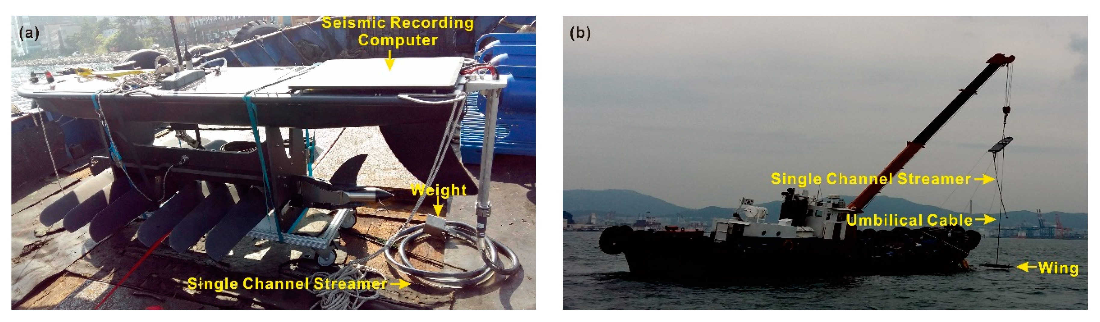
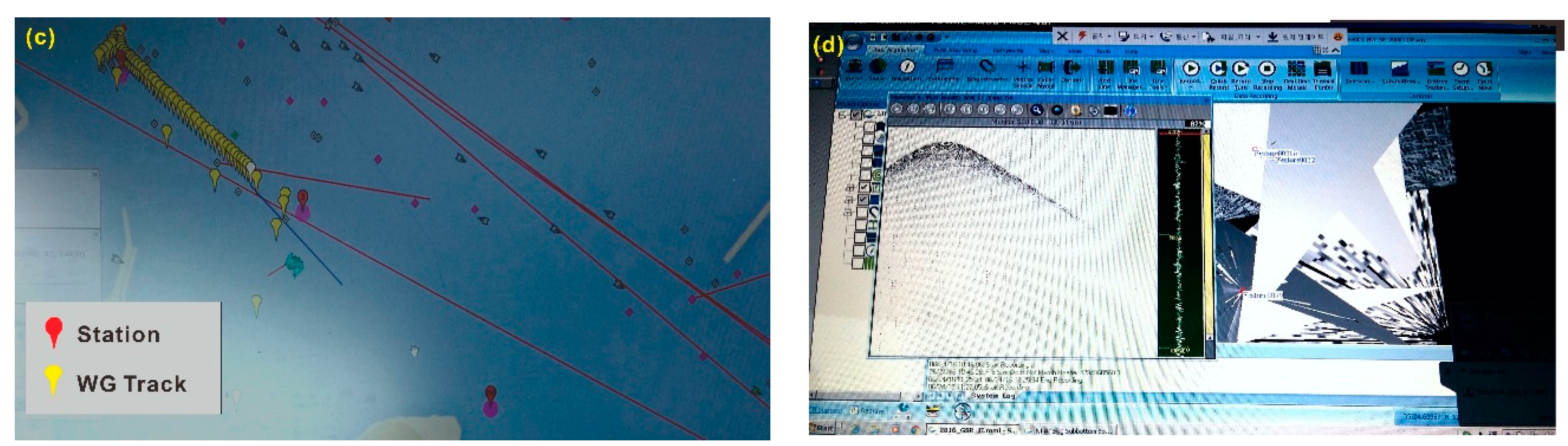
3.2. Field Acquisition

Two parallel northwest–southeast survey lines were plotted, separated by 250 m (Figure 3a). The power of the sparker was 2000 J. The nominal vessel speed was 3.5 knots (approximately 6.5 km/h), and the shot time interval was 2 s, corresponding to a distance of approximately 3.6 m. All data acquisition parameters are summarized in Table 2.
During the WAS survey, the WG track had a diameter of 80.6 m (Figure 3b). A total of 584 traces were recorded at the WG’s single channel streamer, and 501 traces were recorded by shooting the vessel’s streamer from the sparker source. The WG was first deployed using a crane, followed by the single-channel streamer (Figure 4). After setting up the recording equipment, the sparker source was deployed, and the vessel followed the pre-plotted track while maintaining a constant speed. The weather and sea conditions were good during the survey.

4. Data Processing

Recorded seismic data were processed to enhance the signal-to-noise ratio. We first processed the refraction data to calculate the velocities of shallow sedimentary deposits and the acoustic basement. Then, we processed the reflection data to image the interface between the sedimentary deposits and basement.

4.1. Refraction Data Processing

Refracted seismic signals arrive first when the lower medium has a higher wave propagation velocity than the upper medium. Refracted seismic signals are easily seen by crossing wave-fronts during single-shot data collection. In the present study, data were recorded from an array of source points at a single location (i.e., the WG). This differs from conventional seismic refraction data, which are normally recorded by an array of receiver points from a single source point. The reciprocal method provides a reliable solution for analyzing velocity data from a shallow refractor [26]. We considered the sparker source points to be the receiver points and the WG station as the source point, under the assumption of reciprocity.
Therefore, the 584 seismic traces collected at the WG were equal to the refracted gathering from source points at the WG’s position. Raw traces and their amplitude spectra are shown in Figure 5a and show low frequency noise contamination. To enhance the visibility of first-arrival events and to reduce the low frequency noise, three filters were applied (Table 3). After application of the filters, low-frequency noise was reduced. (Figure 5b). Although the result of applying the filters is not apparent, this removed a spike event, thus allowing automatic picking. The present data did not contain many traces that were required to be picked manually. However, automatic picking is needed when the processing involves an increased number of traces.
We selected first-arrival signals for offsets using the SeisSpace software version 5000.10.0.4 of Landmark Halliburton Company. Both manual (Figure 6a) and auto-picking (Figure 6b) modules were able to identify the first-arrival event. Automatic picking is recommended when the seismic traces are numerous, in particular, for greater consistency.
We calculated subsurface velocity based on the relationship between travel time and offset distance (Figure 7). The WG recorded signals when it approached (forward) and moved away (reverse) from the shooting vessel. The slope values calculated on both sides of a refraction point were considered as the velocities of the upper and lower layers (Figure 7) [19]. The average velocities were 1557 and 3507 m/s for the upper shallow sedimentary deposits and deeper acoustic basement, respectively. Above the seafloor, we used a constant acoustic velocity of seawater of 1480 m/s.

4.2. Reflection Data Processing

We divided seismic traces (Figure 6) into left and right directions from the WG position with a vertical profile of velocity from Figure 7 using offsets within 300 m to observe the seismic amplitude with respect to travel time (Figure 8). A strong amplitude was observed at travel times of 70–100 ms, indicating the acoustic basement. These traces represent the reflected signals at the specific WG position, which shows variation in the amplitude in the depth direction. Subsurface images can be created if such data are collected over sufficient distances. However, the refraction data were recorded only at a single location to test the survey system, so we complemented the calculated velocities with single-channel reflection data recorded at the source vessel.
The single-channel reflection data did not contain offset times; therefore, using only single-channel data, it is impossible to determine subsurface velocities. However, reflection data show the structures of shallow sedimentary deposits and the subsurface acoustic basement. When imaging structures for offshore energy, the goal of seismic surveys is to define the acoustic basement, which provides a strong base for pilings. Thus, appropriate drilling procedures can be planned using seismic data.
To produce seismic sections adequate for differentiating shallow sedimentary deposits and the acoustic basement, we enhanced the sections, identified the horizons, and overlaid the calculated velocities. Enhancement of the single-channel data was achieved via geometric manipulation, trace binning, and Ormsby bandpass filtration of 10–120–400–600 Hz (Figure 9). Soft unconsolidated sedimentary deposits and a strong basement could be clearly distinguished in the processed section.
We first used the automatic picking module to identify consecutive high peak values, horizontally in the lateral direction (Figure 10a). We then overlaid the velocities on the interpreted seismic sections to clearly show the layers (Figure 10b). Using this information, offshore energy facilities could be designed safely.

5. Discussion

We used a WG seismic survey system to collect refraction and reflection data at a shallow offshore site near a port. The present results demonstrate the feasibility of such surveys to derive information on velocities and interfaces in a two-layered subsurface. However, several improvements are required before applying this approach to deeper water and subsurfaces with more complicated layering. First, static correction should be applied to improve the accuracy of travel times, which can in turn improve subsurface velocity estimates. Additionally, the number of receivers should be increased. Using more WGs increases the points from which refraction can be recorded. Furthermore, coordinated groups of WGs can record offset reflection data so that deeper and more complex subsurface interfaces can be imaged. Reflection data could be used in semblance analysis of velocity to capture lateral velocity variation.
The demand for surveys of offshore subsurfaces to develop ocean energy infrastructure may lead to improved survey systems with multiple WGs, which would contribute to the engineering field. The present survey system could help improve cost efficiency and could broaden the applications of such surveys. WGs could be used not only for refraction and reflection studies but also for three-dimensional or vertical seismic profiling.

6. Conclusions

This study shows that a WG system can be used in seismic surveys to obtain information required for offshore structure development. Recorded seismic signals are processed by refraction and reflection techniques to calculate the velocity of the subsurface and to image its structure. The calculated velocities of shallow sedimentary deposits and the acoustic basement are compared with the results of a reference study, at 1650 and 2200 m/s, respectively. The depth of the acoustic basement with depth conversion can provide a reference for the construction of offshore structures. The present survey system using a WG allows efficient exploration for offshore energy development.

Author Contributions

Conceptualization, S.C. and Y.-J.K.; methodology, Y.-J.K.; investigation, S.C., Y.-J.K., J.-H.C., J.-K.K. and S.H.; data curation, J.-K.K. and S.H.; writing—original draft preparation, S.C. and Y.-J.K.; writing—review and editing, S.C., Y.-J.K. and J.-H.C. All authors have read and agreed to the published version of the manuscript.

Funding

This research was funded by the Korea Institute of Geoscience and Mineral Resources (KIGAM), grant numbers 20-3413-1 (Technology development for storage efficiency improvement and safety assessment of CO2 geological storage) and 20-3111-2 (Geological survey in the Korean Peninsula and publication of the geological maps).

Institutional Review Board Statement

Not applicable.

Informed Consent Statement

Not applicable.

Data Availability Statement

Not applicable.

Acknowledgments

We wish to thank Sung-Ryul Shin and Wookeun Chung of Korea Maritime and Ocean University for their support in data acquisition.

Conflicts of Interest

The authors declare no conflict of interest.

References

  1. Wynn, R.B.; Huvenne, V.A.I.; Le Bas, T.P.; Murton, B.J.; Connelly, D.P.; Bett, B.J.; Ruhl, H.A.; Morris, K.J.; Peakall, J.; Parsons, D.R.; et al. Autonomous under water vehicles (AUVs): Their past, present and future contributions to the advancement of marine geoscience. Mar. Geol. 2014, 352, 451–468. [Google Scholar] [CrossRef] [Green Version]
  2. Paull, C.K.; Normark, W.R.; Ussler, W., III; Caress, D.W.; Keaten, R. Association among active seafloor deformation, mound formation, and gas hydrate growth and accumulation within the seafloor of the Santa Monica Basin, offshore California. Mar. Geol. 2008, 250, 258–275. [Google Scholar] [CrossRef]
  3. Maier, K.L.; Brothers, D.S.; Paull, C.K.; McGann, M.; Caress, D.W.; Conrad, J.E. Records of continental slope sediment flow morphodynamic responses to gradient and active faulting from integrated AUV and ROV data, offshore Palos Verdes, southern California Borderland. Mar. Geol. 2017, 393, 47–66. [Google Scholar] [CrossRef]
  4. Campbell, K.J.; Kinnear, S.; Thame, A. AUV technology for seabed characterization and geohazards assessment. Lead. Edge 2015, 34, 170–178. [Google Scholar] [CrossRef]
  5. Jakobsson, M.; Gyllencreutz, R.; Mayer, L.A.; Dowdeswell, J.A.; Canals, M.; Todd, B.J.; Dowdeswell, E.K.; Hogan, K.A.; Larter, R.D. Mapping submarine glacial landforms using acoustic methods. Geol. Soc. Lond. 2016, 46, 17–40. [Google Scholar] [CrossRef] [Green Version]
  6. Austin, J. The potential for Autonomous Underwater Gliders in large lake research. J. Great Lakes Res. 2013, 39, 8–13. [Google Scholar] [CrossRef]
  7. Villareal, T.A.; Wilson, C. A comparison of the Pac-X Trans-Pacific Wave Glider data and satellite data (MODIS, Aquarius, TRMM and VIIRS). PLoS ONE 2014, 9, e92280. [Google Scholar] [CrossRef] [PubMed] [Green Version]
  8. Dolman, S.J.; Green, M.; Simmonds, M.P. Marine renewable energy and cetaceans. In Report for Scientific Committee; Whale and Dolphin Conservation Society: Wiltshire, UK, 2007. [Google Scholar]
  9. Guinan, J.; McKeon, C.; O’Keefee, E.; Monteys, X.; Sacchetti, F.; Coughlan, M.; Aonghusa, C.N. INFOMAR data in the EMODnet geology data portal supports marine spatial planning and offshore energy development in the Irish offshore. Qt. J. Eng. Geol. Hyd. 2020, 51. [Google Scholar] [CrossRef]
  10. Cha, Y.H.; Jo, C.H.; Suh, J.H. Water bottom seismic refraction survey for engineering applications. Geosys. Eng. 2003, 6, 40–45. [Google Scholar] [CrossRef]
  11. Hamilton, E.L. Sound velocity as a function of depth in marine sediments. J. Acoust. Soc. Am. 1985, 78, 1348–1355. [Google Scholar] [CrossRef] [Green Version]
  12. Barr, F.J. New seismic technique is improving hydrocarbon recovery. J. Pet. Tech. 1996, 48, 592. [Google Scholar]
  13. Mitchell, S. Nodes improve seismic quality, cost. In The American Oil and Gas Report; AOGR: Derby, KS, USA, 2011. [Google Scholar]
  14. Summers, T.; Michell, S.; Barley, B.; Foster, M. Recent advances in the development and application of wide azimuth seismic technology. In Proceedings of the Offshore Technology Conference, Houston, TX, USA, 6 May 2010. [Google Scholar]
  15. Long, A.S.; Pramik, W.; Fromyr, E.; Laurain, R.; Page, C. Multi-azimuth and wide azimuth lessons for better seismic imaging in complex settings. ASEG Ext. Abstr. 2006, 1–5. [Google Scholar] [CrossRef]
  16. Moldoveanu, N.; Salama, A.; Lien, O.; Muyzert, E.; Pai, S.; Monk, D. Marine acquisition using autonomous marine vehicles: A field experiment. In Proceedings of the SEG Technical Program Expanded Abstracts, Denver, CO, USA, 26–31 October 2014; p. 5183. [Google Scholar]
  17. Moldoveanu, N.; Caprioli, P.; Kjellesvig, B.A.; Ishak, M.; Beecher, M.; Mulisheva, L.; Pai, S. Marine seismic acquisition with autonomous marine vehicles towing 3D sensor arrays. Lead. Edge 2017, 36, 558–565. [Google Scholar] [CrossRef]
  18. Palmer, D. The Generalized Reciprocal Method of Seismic Refraction Interpretation; Society of Exploration Geopysicists: Houston, TX, USA, 1980. [Google Scholar]
  19. Lankston, R.W. High-resolution refraction data acquisition and interpretation. In Geotechnical and Environmental Geophysics; Review and Tutorial; Ward, S.H., Ed.; Society of Exploration Geophysicists: Tulsa, OK, USA, 1990; Volume I, pp. 45–73. [Google Scholar]
  20. Ewing, J.; Leyden, R.; Ewing, E. Refraction shooting with expendable sonobuoys: Geological notes. AAPG Bull. 1969, 53, 174–181. [Google Scholar]
  21. Pei, Y.; Kan, G.; Zhang, L.; Huang, Y.; Liu, Z.; Liu, B.; Yan, K. Characteristics of source wavelets generated by two sparkers. J. Appl. Geoph. 2019, 170, 103819. [Google Scholar] [CrossRef]
  22. Shin, S.R.; Kim, Y.J. Development of high resolution seismic data acquisition system with shallow marine source and its field applications. J. Korean Soc. Min. Energy Res. Eng. 2005, 42, 454–464. [Google Scholar]
  23. Shin, S.R.; Kim, C.S.; Jo, C.H. A study on the shallow marine site survey using seismic reflection and refraction method. Mulli-Tamsa 2008, 11, 109–115. [Google Scholar]
  24. Kim, Y.; Cheong, S.; Koo, N.; Chun, J.; Kim, J.; Hwang, K.; Lee, H.; Heo, S.; Moon, K.; Jeong, C.; et al. Case study of the shallow seismic refraction survey using wave glider. Geoph. Geoph. Exp. 2017, 20, 43–48. [Google Scholar]
  25. Ha, J.; Ko, H.; Cho, H.; Chung, W.; Ahn, D.; Shin, S. A proposal of marine geophysical exploration techniques for offshore plant installation. J. Korean Soc. Mar. Eng. 2013, 37, 242–251. [Google Scholar]
  26. Hawkins, L.V. The reciprocal method of routine shallow seismic refraction investigations. Geophysics 1961, 26, 806–819. [Google Scholar] [CrossRef]
Figure 1. Equipment used in the seismic refraction survey: (a) diagram of the wave glider (modified from [7]) and (b) schematic of the artificial sound source and receiver (sparker and streamer, respectively).
Energies 14 00297 g001
Figure 2. Schematic diagram of the seismic refraction data acquisition system.
Energies 14 00297 g002
Figure 3. (a) Map of the study area marked with the vessel and wave glider survey tracks, and (b) subset of a survey track enlarged from the green dotted rectangle in (a): the circles indicate every 50 shot points.
Energies 14 00297 g003
Figure 4. Photographs of (a) the wave glider (WG) equipped with a single-channel streamer, (b) the launch of the WG, (c) tracking and monitoring the position of the WG via the software manufacturer’s webpage, and (d) real-time quality-control monitoring of seismic data via a remote connection (modified from [24]).
Energies 14 00297 g004aEnergies 14 00297 g004b
Figure 5. Seismic data recorded by the unmanned wave glider (a) before and (b) after filter application, and (c) amplitude spectra of (a) and (b).
Energies 14 00297 g005aEnergies 14 00297 g005b
Figure 6. Results of first break picking: (a) manual and (b) automatic.
Energies 14 00297 g006
Figure 7. Calculation of velocity based on the relationship between travel time and offset distance: the forward and reverse directions indicate positive and negative offset distances, respectively.
Energies 14 00297 g007
Figure 8. Seismic traces from the wave glider with (a) negative offset, (b) calculated velocities via travel time, and (c) positive offset.
Energies 14 00297 g008
Figure 9. Single-channel-recorded sections after processing.
Energies 14 00297 g009
Figure 10. Processed reflection data from the single-channel seismic section image: (a) the interfaces identified by the auto-picker, where the blue line marks the seawater–shallow sediment interface and the red line marks the sedimentary deposits–acoustic basement interface, and (b) the interface from (a) overlain with velocity data.
Energies 14 00297 g010
Table 1. The wave glider specifications.
VersionWave Glider SV2
Dimension
-
Float
-
Sub
-
Wings
210 cm × 60 cm
40 cm × 191 cm
107 cm wide
Weight90 kg
Power
-
Battery
-
Solar power
665 Wh Li-Ion
112 W (peak)
Water Speed0.5–1.6 knots
Station-Keeping40 m radius
Table 2. Survey equipment and data acquisition parameters.
WAS
(Red Curved Line)
Seismic Reflection Survey
(Light Blue Line)
Sparker (SIG)
-
Power
2 kJ2 kJ
-
Shot interval
2 s2 s
Recording
-
Software
SonarWiz 6.0Mini-Trace
- Sampling interval(Chesapeake Technology)
0.1 ms
(Geo Marine Survey Systems)
0.066 ms
Streamer
-
Length
3 m7 m
-
Elements
1024
Table 3. Filters applied to noise reduction.
Parameters
Time-Frequency Domain Noise Reduction
-
Time window
0–400 ms
-
Frequency range
10–1000 Hz
Spike and Noise Burst Edit
-
threshold
3.0
-
operator length
5 samples
Bandpass filter
-
type
Ormsby bandpass
-
frequency
60–120–400–600
Publisher’s Note: MDPI stays neutral with regard to jurisdictional claims in published maps and institutional affiliations.

