Article

A Current Sensor Fault Tolerant Control Strategy for PMSM Drive Systems Based on Cri Markers

by
Kamila Jankowska
and
Mateusz Dybkowski
*
Department of Electrical Machines, Drives and Measurements, Wroclaw University of Science and Technology, 50-370 Wroclaw, Poland
*
Author to whom correspondence should be addressed.
Energies 2021, 14(12), 3443; https://doi.org/10.3390/en14123443
Submission received: 5 May 2021 / Revised: 4 June 2021 / Accepted: 9 June 2021 / Published: 10 June 2021
(This article belongs to the Special Issue Applications of Modern Methods to Control of Electric Drives)

Abstract

:
The paper describes a vector-controlled fault tolerant control (FTC) structure for permanent magnet synchronous motor (PMSM) drives. As a control algorithm, the classical field oriented control was applied. For the proper operation of this drive, minimum two current sensors are necessary, however, in the FTC drives additional redundant transducers are applied. Each measuring sensor, including current sensors, are susceptible to damage and can lead to unstable operation of the drive. The presented control structure, with a diagnostic and compensation system, is robust to the typical current sensor faults—lack of signal, intermittent signal, variable gain, signal noise and signal saturation. The fault detection algorithm is based on the signal method. The fault diagnostic system is tested in two control algorithms—the scalar control and vector control ones—to demonstrate the transient of the faulted signals, detection signals and detection time. After current sensor fault appearance, its influence on the control structure, especially speed transient, is compensated using non-sensitive components. The analysis is presented for all the abovementioned faults for different speed conditions.

Graphical Abstract

1. Introduction

Modern industry uses the latest technologies to optimize work and increase safety. Mechanical and electronic devices have a certain durability and can be damaged, leading to a stoppage in a production or technological process. Each failure leads to unacceptable losses. There is therefore an increasing effort to develop systems that can be resilient or compensate for various types of faults in industrial processes.
It is especially important in industries such as spacecraft, aircraft and automotive applications. This issue also applies to electric drives, which are complex and complicated systems where even a minor failure may have serious consequences [1]. Electrical drive systems constitute one of the most important parts of industry. Electrical drives which use technologies leading to increased safety at the level of the appearance of mechanical and electrical damages are called fault tolerant control systems (FTCS). FTCS should automatically detect any type of fault (mechanical or electrical) to provide safe performance. Detection and compensation algorithms must be non-invasive methods and must guarantee the stable operation of the drive system.
A general FTC scheme is presented in Figure 1 [2]. One of the most important parts of this system is an fault detection and isolation (FDI) block, which is responsible for providing the supervision system with information about the location and severity of any faults.
According to the literature, FTCS can be divided into passive (PFTCS) and active (AFTCS) systems [3]. In the passive system, stability is provided by using a properly designed controller, without use of the controller reconfiguration and the FDI block, even when a fault occurs. Therefore this method is computationally interesting [3] and much easier to implement [4,5,6,7,8,9,10,11,12,13,14,15,16,17,18,19,20,21,22]. In [3], passive FTC, robust to the stator inter-turn short-circuit fault (ITSC) of an induction machine (IM), is presented. The implemented system is based on a sliding mode controller. This solution provides better dynamical properties during normal work conditions and also when a failure occurs. Besides, the author used a SMO (Sliding Mode Observer) to estimate the rotor flux (in vector controlled induction motors (IMs)) and avoid using a flux sensor. The stability of system operations was analysed by the Lyapunov stability theorem. Experimental results showed that the implemented FTCS allow one to achieve a stable work situation for an IM even if an ITSC fault occurs. The main drawback of this kind of a system is its inability to detect and then compensate failures, hence the failure may proceed.
In active systems a reconfiguration mechanism is required. AFTCS provides real-time fault diagnosis in contrast to the passive one. When a fail occurs, the system has to detect and localize it, then compensate for its impact on work conditions. In [4], an example of AFTCS robust to ITSC is presented. A high order sliding mode observer is used to detect and localize the fault. When a defect occurs the controller is reconfigured and additional signals are used as failure alarms.
In [5], FTCS with the ability of operating during IGBT transistor and sensor faults is presented. In the proposed system adaptive thresholds and normalized diagnostic variables are used. The detection algorithm is based on the Park transformations. Then, the calculated signals are used for IGBT fault detection. This algorithm is simple in its practical implementation.
In the case of drive systems, three main types of faults can be indicated, starting with power electronics faults, which can be divided into power semiconductor faults and DC bus faults [17,18,19]. Another type of failure are mechanical faults [20,21,23] and electrical faults [24,25,26] concerning the motor. The last type are sensors faults, which may concern mechanical or electrical variables [2]. Each of the mentioned failures is the object of research by scientists dealing with FTC. This article focuses only on the failures of stator current measuring sensors.
To ensure proper work, a drive system has to be equipped with at least two current sensors, a voltage sensor and a speed sensor. Inappropriate measurements can affect the whole drive system. Sensors are subject to various faults, for example interruptions in a wire connection. It is estimated that 14.1% of all system failures are caused by sensor faults [6], which are a critical drive system component in the case of permanent magnet synchronous motors (PMSMs). Based on [9], diagnosis approaches are divided into two main types: model- [27,28,29,30,31] and signal [32,33,34]-based methods.
In model-based algorithms, system identification is required [35]. In signal-based methods, essential fault features are extracted from the measured signals based on mathematical equations or signal processing methods [36]. Then, based on symptom analysis, a diagnostic decision is made. This type of methods require prior knowledge of the parameters of healthy systems.
Most research works dealing with sensor fault tolerant control are based on sliding mode observers [7,12,13,14]. Reference [7] presents an example of an active system based on this type of an observer. Unknown disturbances, which could cause an incorrect diagnosis are eliminated by the sliding mode control methodology. An algorithm is insensitive to various uncertainties and robust to false-positive false detection. The phase current sensor faults are reconstructed by means of the adaptive method.
Reference [9] presents a current sensor FTC for an IM drive system. The control system allows failure in two phases at the same time. The system is based on three independent observers. When a fault occurs, the algorithm detects and localizes it, then it switches the system to the FTC mode, even when only one phase sensor is healthy. The measured signal is replaced by the estimated one, based on the adaptive observer. Current sensor fault detection based on observers is also presented in [10]. The current estimation algorithm uses d- and q-axes currents. Importantly, the method is independent of the inverter switching. In this system speed is calculated using a MRAS (Model Reference Adaptive System) type estimator. A decision is based on a logic algorithm. The presented algorithm works with different types of drives, including EV and increases the level of the security. In the case of sensor failure, the system is protected against complete destruction. After simulations conducted in Matlab/Simulink, the algorithm was verified by experiments using dSpace 1104.
An example of the signal-based method is given in [6], which presents current sensor detection and isolation based on DC link current estimation. At first, the algorithm calculates the input electrical power based on DC link voltage and current, then the DC link current residual is calculated and used as a fault indicator. When the measured signal is correct, then the estimated and measured value difference is near to 0. If the difference between the measured and estimated value is higher than the defined small value, the information about a fault appears. To localize and isolate the fault an algorithm was also implemented. Determining the location of the failure is based on phase signal estimation and residuals examination. The simulations were conducted for fixed offset and random scale faults and show the effectiveness of the developed algorithm.
Another example of a signal-based method is presented in [8], which describes phase current value reconstruction after a fault occurrence based on the DC-bus voltage in the intermediate circuit of the voltage-source inverter and rotor speed. This paper presents a solution for a vectored control induction motor which allows stable work without switching to open loop control. Simulation results for the reconstruction algorithm are presented for the open and closed loop system. The simulation tests were carried out for two stages: the steady state of drive operation and various work conditions. After the simulation verification of the estimator, an experiment was carried out, which confirms the efficacy of the presented method.
Article [11] also presents a signal-based method. The algorithm is implemented for PMSM in field-oriented vector control based on the reasonable estimation of the current amplitude. The presented control structure is robust to single or double phase faults. Online revision is presented for gain variation and zero offset. The proposed method requires only the information of three-phase currents and the position of the rotor, instead of an accurate system model with explicit parameters. The proposed method is simple and computationally interesting.
Methods based on shallow neural networks are also used to identify damage to measuring sensors. This approach allows one to achieve good results without any information about the mathematical model of the object. One of the many fears related to this approach to the issue of diagnostics is described in [15,28].
Due to the growing interest in electrical drives [36,37,38] in the topic connected with deep learning methods. This algorithm can be also used in the detection and isolation of the faults in electric drives. In [25] the authors describe the application of a convolutional neural network (CNN) for the detection and classification of ITSC. Contrary to popular analytical methods, this approach makes it possible to use diagnostic signal direct processing. The research was supported by an experiment for various levels of stator failures.
Another example of use methods based on artificial intelligence (AI) is [39], which describes fault diagnosis methods using machine learning. Firstly a signal is processed by a discrete wavelet transform to extract features, then classifiers from the Matlab Classification Learner Toolbox are used: decision trees, space vector machine (SVM), k-nearest neighbours (KNN) and ensemble. The algorithm recognizes different mechanical faults such as bearings failures, an unbalanced shaft rotation, broken bars and combined faults. Experiments were conducted under healthy, single-fault and multi-fault conditions and confirmed the possibility of implementing the classifier in a practical industrial system to realize real-time fault diagnosis for variable frequency drives (VFDs) IM [40,41].
In this paper, the current sensor FTC based on the signal method is presented. The algorithm also allows for fault compensation in the open and close loop structure. This article presents a method for stator current sensor fault detection based on Cri markers. Previous works presented the results of the operation of such a system obtained for an induction motor operating in DTC (Direct Torque Control) and DFOC (Direct Field Oriented Control) systems. The results showed high effectiveness of the proposed algorithm for this type of objects [40,41]. This article shows that the diagnostics and compensation system based on the mechanism of transformation to a stationary coordinate system can also be successfully used in drives with PMSM motors. This system is characterized by versatility, which other systems of detection and compensation of stator current sensors failures lack. The only condition necessary to implement the presented algorithm is system symmetry.
The research was conducted for the field oriented control (FOC) of a PMSM drive system. The article is divided into seven parts. Firstly, the state of research art is discussed. In the second section, the mathematical model of the tested motor and control structures are presented. The third section shows the manner of conducting sensor fault simulation and its impact on control structures. The fourth part presents the detection and isolation algorithm based on Cri markers. The effectiveness of the implemented algorithm with fault compensation is presented in the fifth section, using Matlab/Simulink simulations, respectively. The sixth section contains our experimental results. The last part of this paper contains a short summary of the achieved results and further research plans.
Thus, the main goal of this article was to demonstrate stator current sensor fault detection algorithms for the vector control (FOC) of the PMSM drive systems based on an active detection system [21]. The proposed algorithm and control structure guarantee stable work of the drive even during fault conditions. The diagnostic method was analysed and tested under different drive operation conditions. The simulation results of the proposed fault tolerant control methods are presented.

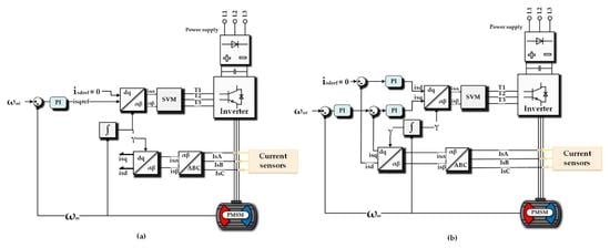
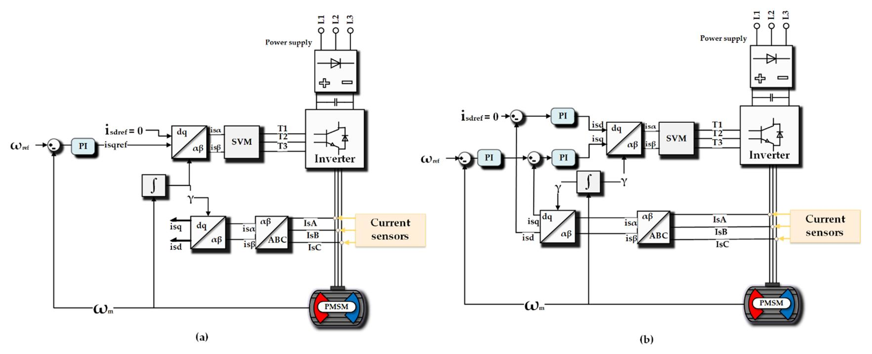
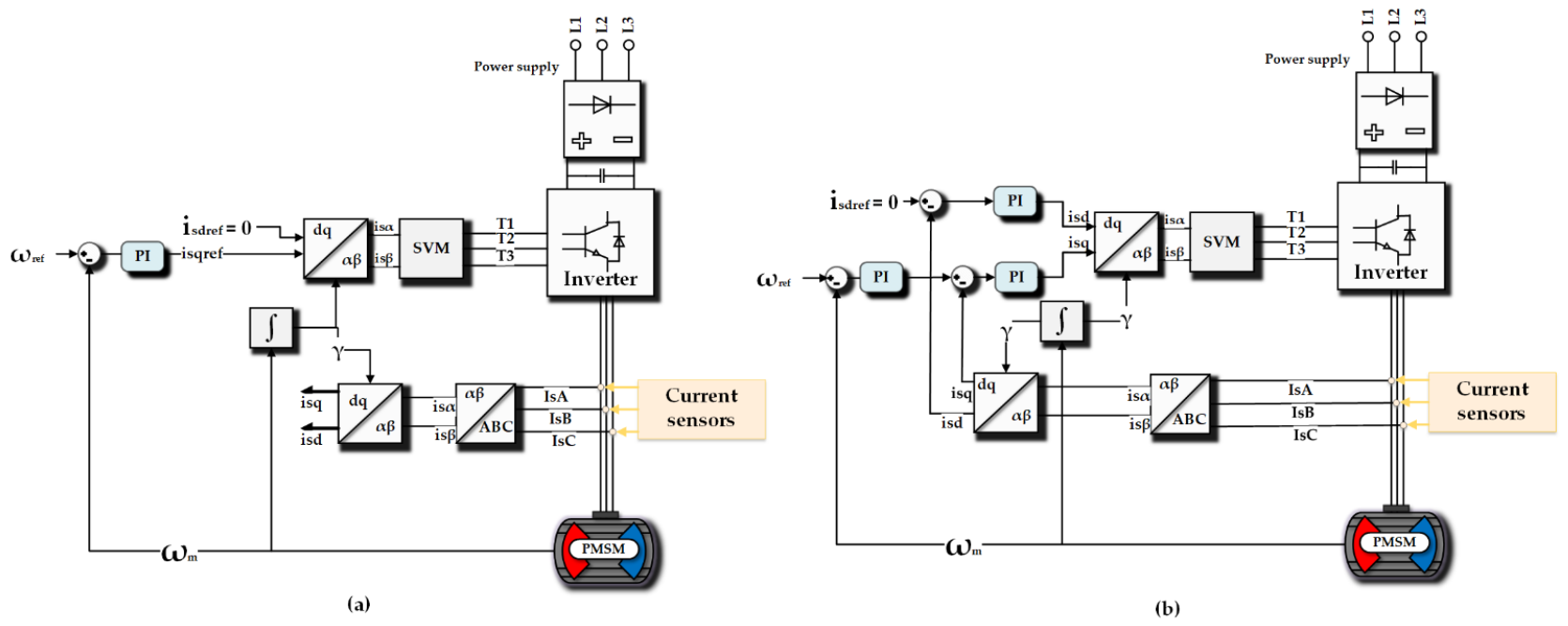
2. Mathematical Model of the Vector Controlled PMSM Drive System

Describing the model of a PMSM several simplifications should be taken into account, such as: three phase symmetrical stator winding, magnetic circuits are linear, isotropic (saturation, eddy currents, and hysteresis are ignored), constant resistance and inductance [37]. In the ABC reference frame the stator voltage and the stator flux can be expressed as:
U s   = R s I s + d d t Ψ s
Ψ s = L s I s + Ψ PM
where:
R s = R s 0 0 0 R s 0 0 0 R s , L s = L s M s M s M s L s M s M s M s L s ,
I s = I sA I sB I sC , U s = U sA U sB U sC
where Rs—stator resistance, Ls stator inductance, M s mutual inductance between stator phases, Ψ PM —flux generated by permanent magnets, which can be expressed by Equation (6). The electrical angle is defined by Equation (5):
θ e = p p θ m
Ψ PM = Ψ PM cos ( θ e ) Ψ PM cos ( θ e 2 3 π ) Ψ PM cos ( θ e + 2 3 π )
the electromagnetic torque is defined by Equation (7):
T e = E s I s T Ω m
where E S —voltage vector induced by the stator flux linkage, Ω m —mechanical speed of the motor.
The equation of motion for a PMSM can be described as follows:
J d d t Ω m = T e T L
θ m =   d Ω m d t
where J—drive system inertia, Te, TL—electromagnetic and load torque, θm—rotor mechanical position.
Research was carried out for two types of control structure. The first one does not require current feedback. Control is based on speed value and rotor position [38]. This structure is used to perform fault analysis and pre-check the fault detector. The structure contains current sensors only for current observation. The second type of control structure is the most commonly used field-oriented control structure. The basic diagrams of both structures are presented in Figure 2. Simulations were conducted for PMSM with surface mounted magnets with the parameters presented in Table 1. To this analysis the Euler method was used with fixed step size equal 1 × 10⁻⁶ s.
The transients of speed for a few reference values for the scalar and field-oriented control under normal conditions are presented in Figure 3.
Although the scalar control does not require current sensors and is easier to implement and parameterize, the field-oriented control allows one to obtain a much better fit between the measured and reference speed and the improvement of system dynamics.

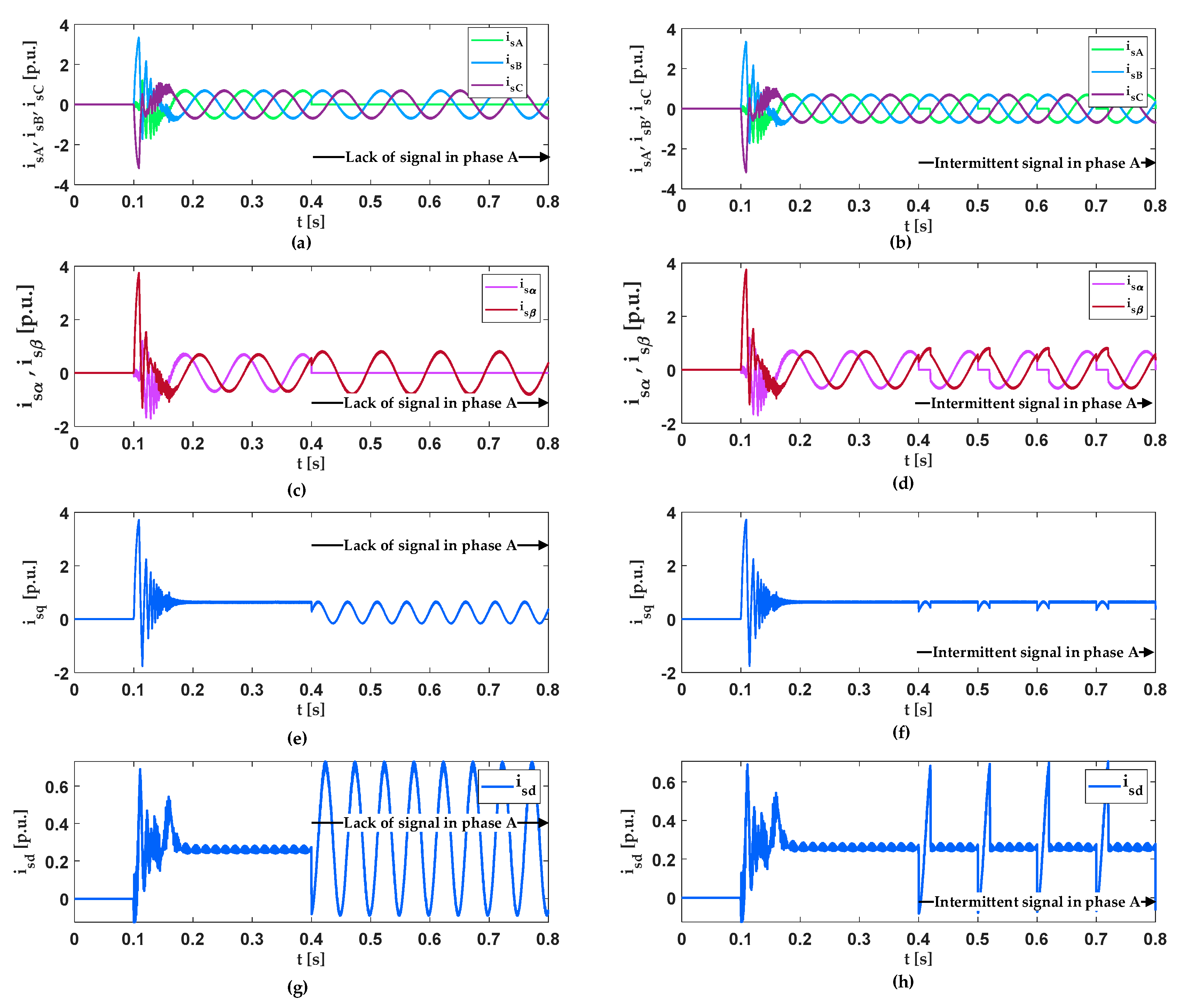
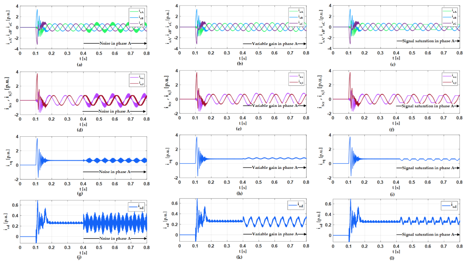
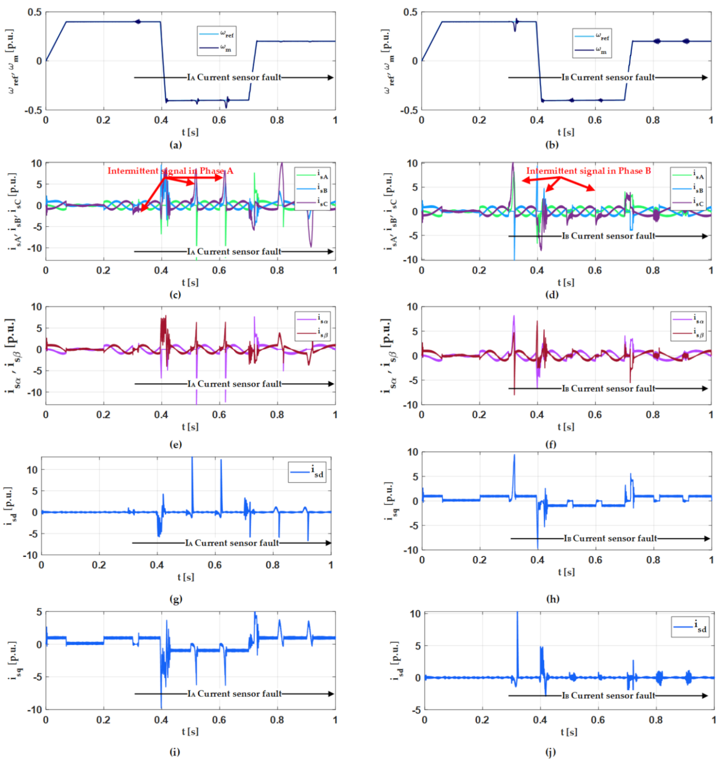
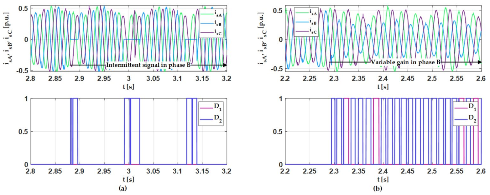
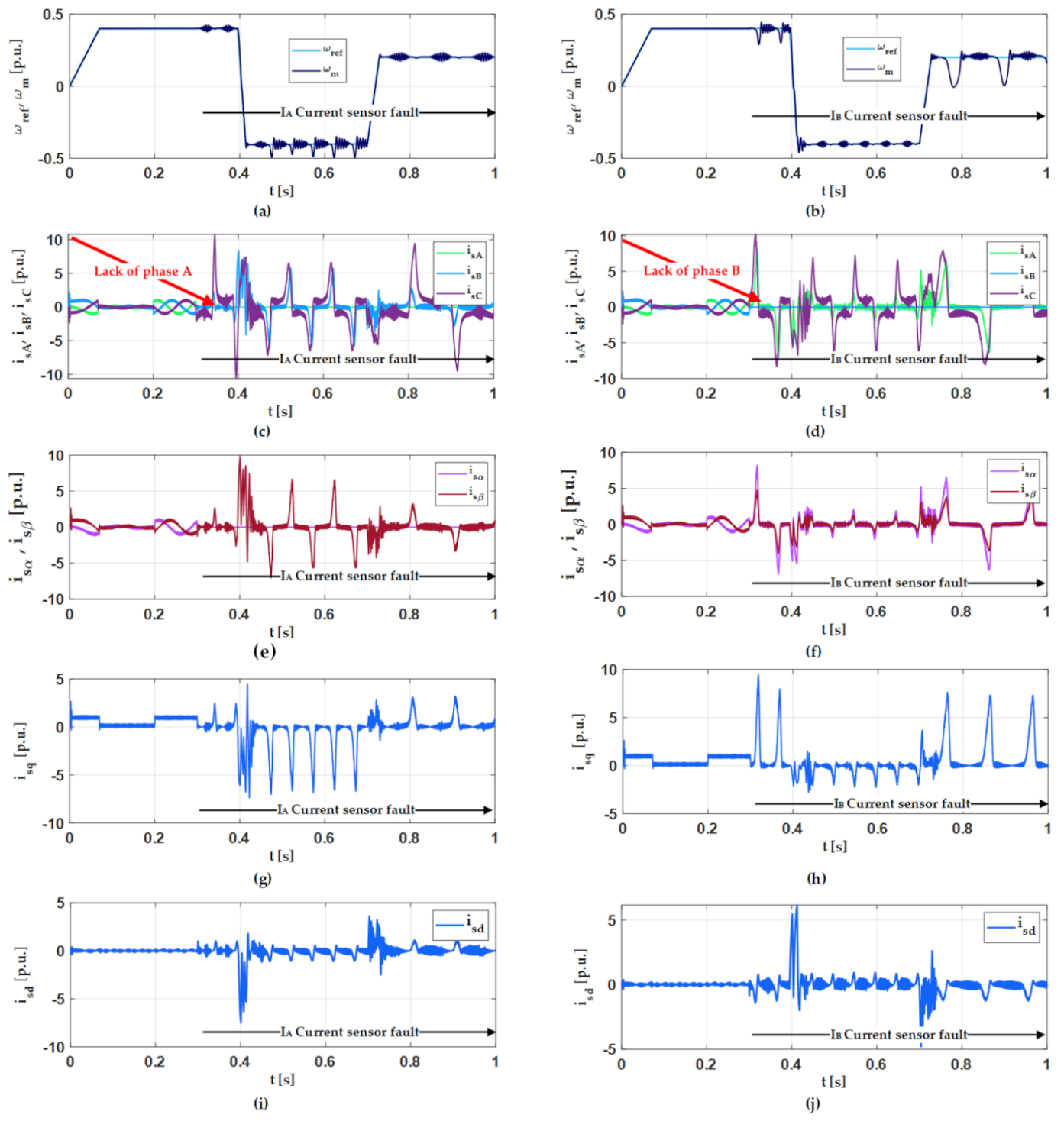
3. Current Sensors Fault Analysis

In this part of the paper, the analysis of the current sensor faults in comparison with the control structures is presented. The tests were carried out for two control systems described in the previous section. In the scalar control with rotor speed feedback and in the vector control system. This approach allows for the observation of the faults (scalar control) and the observation of the failure’s impact on the closed-loop control process. The results in the two structures are very different.
For the proper operation of the FOC algorithm, information about the stator current is required. In the third phase, the system controlled by vector algorithms requires at least two phase current sensors to ensure proper work conditions. The third current can be calculated based on these two measured signals. The measured signals are transformed to the stationary reference frame and later to the dq frame system. Those two currents are used in the FOC system. The most common current sensor faults can be described and simulated using the equations presented in Table 2 [15].
The analysis presented in this paper was conducted for five types of faults in phase A (a similar result can be obtained for phases B and C). At first, the analysis was carried out for faults influence on phase currents and stator current components in the scalar control structure presented in Figure 2a to more accurately present the fault effect on the current. The results are presented in Figure 4 and Figure 5.
The lack of signal in phase A (presented in Figure 4a,c,e,g) causes a significant observed growth in current components, which makes it impossible to correctly calculate these components in the closed loop control system. The lack of signal in phase A (green colour) causes similar oscillations on the transformed components of the stator current in the d and q axes (not used in the scalar control system). Due to the fact that it is a scalar control system, these currents are not stabilized, as is the case in a vector control system. Research indicates that this type of damage will have significant consequences in the vector control system.
Intermittent signals (Figure 4b,d,f,h) periodically cause similar effects as a lack of signal. The growth in the current components during signal noise and variable gain is not as substantial as during the first mentioned failure, but may cause oscillation in speed transients in a closed loop. Signal saturation besides changing the current value affects its shape.
In the next part of this section the influence of the described types of faults on the properties of the vector controlled PMSM is presented.
In field-oriented control (Figure 2b), the greatest impact on the control structure is exerted by a lack of signal. In phase B, a fault causes more interferences. The intermittent signal fault also significantly disturbs motor control. Other damages are almost unnoticeable in speed transients, the structure compensates for them but they may have serious effects over time. The transients for basic variables with most major faults are presented in Figure 6 and Figure 7.
It can be observed that despite the failure of the stator current sensors, the drive system, controlled by the FOC method, works stably. These results are different from the analyses presented in authors’ papers for drives with induction motors. This is because the vector control structure is similar to the scalar control algorithm (Figure 2) and the machine is a synchronous motor. When the current sensor is damaged, the current control systems see these signals as external disturbances, which lead to the deterioration of the drive’s operation, but do not cause its loss of stability. The speed controller determines the operation of the system. Despite the fact that the drive works, very large oscillations are visible in the measured current signals and the d and q components. The consequence of the vector-controlled drive operation, when the current sensors are damaged, may be the PMSM motor damage (e.g., demagnetization). It is visible that the stator current component in axis d is not kept at the zero value and oscillates around zero. Each peak on this component can be dangerous for the magnets in the rotor.

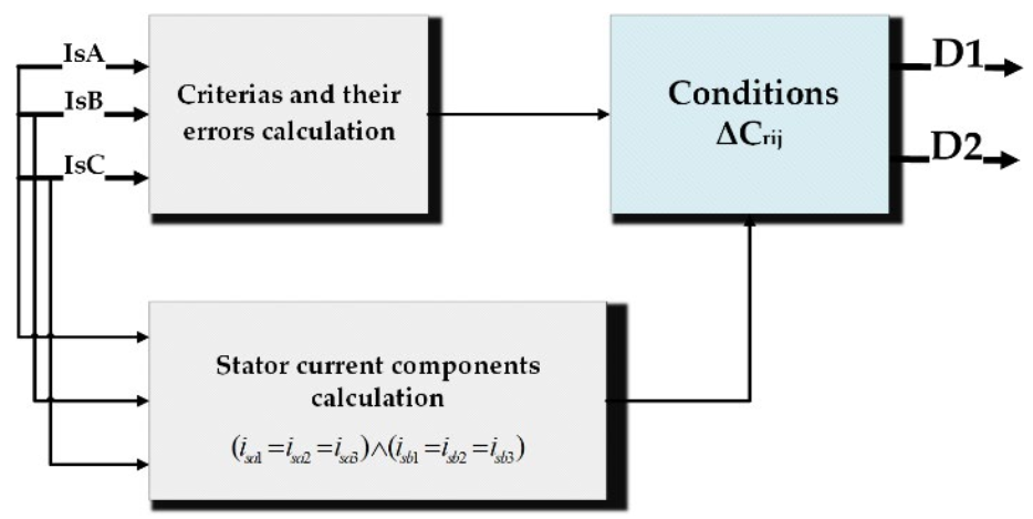
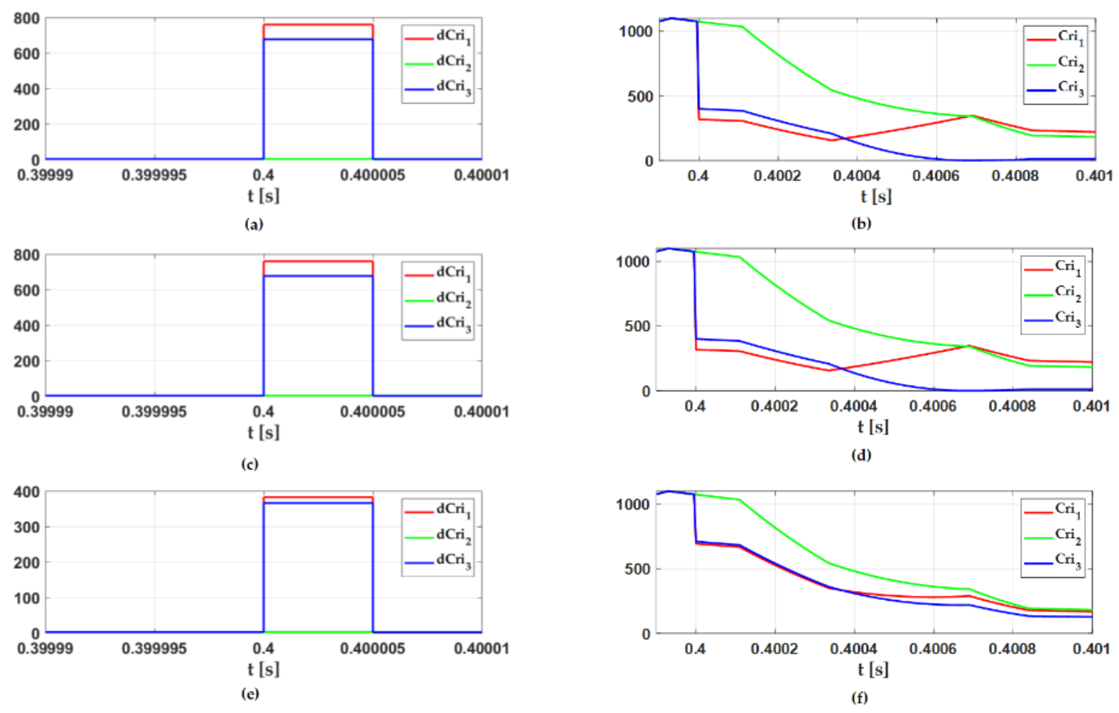
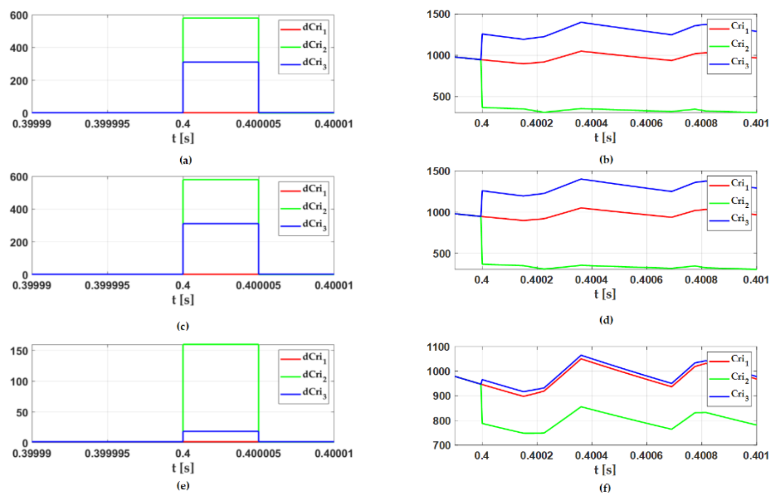
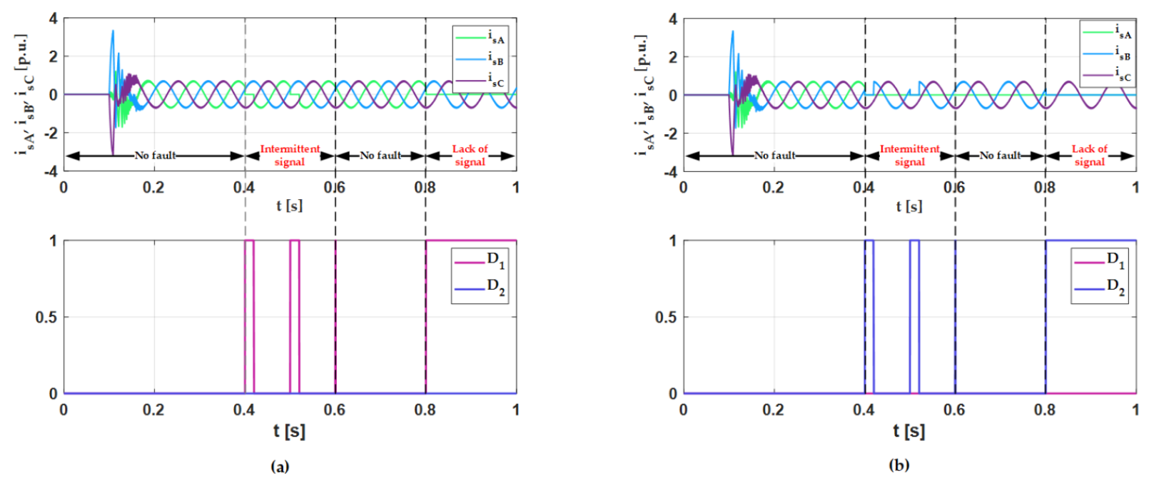
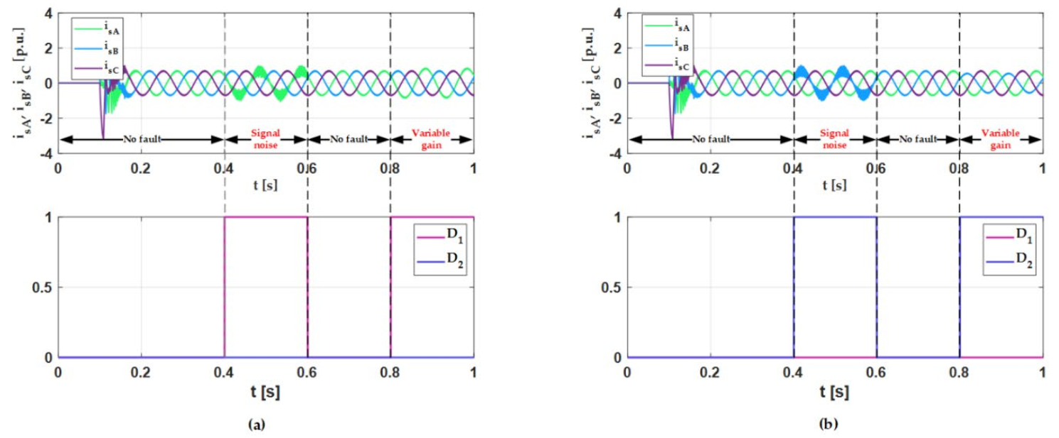
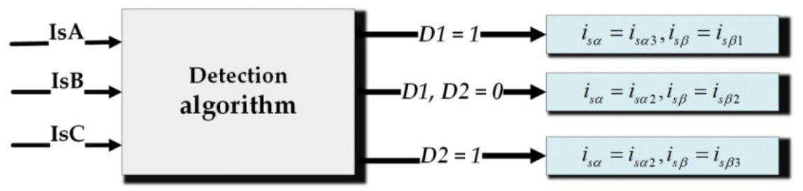
4. Fault Detection and Isolation Algorithm

In the analysed system, three current sensors, one for each phase, can be used. For the control in the “healthy” condition only two sensors are used. The faults of the stator current sensor can be detected based on the following equation:
i A + i B + i C   = f 0
I F f 0 < ε 0 T H E N f i = 0 E L S E f i = 1
where ε 0 is a small constant.
For the faulted sensor, coefficient fi = 1. This proves that there are current sensor faults or other abnormalities in the measured system. Based on this information, it cannot be clearly identified which sensor was broken. It is necessary to provide the fault detection algorithm with additional information.
Therefore, this part of the paper presents the analysis of the method proposed in [36], which is a modification of the detection system proposed in [35] which guarantees the detection of a broken sensor.
In the control structure tested in this paper, two measurements from current sensors are used: in phase A and B. The third current sensor can be calculated from Equation (6).
Damage to a transducer in any phase also significantly affects the current waveforms in the other phases (in the closed loop system). The detection algorithm is based on the markers. Crij markers can detect any of the damages presented in part two in both phases. In a closed control loop, the fault must be detected at the first sample after it occurs, otherwise the second phase is affected by the damage and the exact fault localization is impossible.
This detection algorithm is based on the equations that allow to determine the components of the stator current differently, depending on how many current sensors are used in the control structure:
i s α 1 = 2 3 ( i s A 1 2 ( i s B + i s C ) ) , i s β 1 = 3 3 ( i s B i s C )
i s α 3 = ( i s B + i s C ) , i s β 3 = 3 3 ( i s B i s C )
i s α 2 = i s A , i s β 2 = 3 3 ( i s A + 2 i s B )
It can be seen that each of the presented equations determining the current components depends on the specific currents in the A, B, and C phases.
Criterial markers can be described as:
C r i 1 = ( i s α 3 2 + i s β 1 2 ) , C r i 2 = ( i s α 2 2 + i s β 3 2 ) , C r i 3 = ( i s α 2 2 + i s β 2 2 )
after mathematical substitutions:
C r i 1 = ( ( i s B + i s C ) ) 2 + ( 3 3 ( i s B i s C ) ) 2
C r i 2 = ( i s A ) 2 + ( 3 3 ( i s A + 2 i s C ) ) 2
C r i 3 = ( i s A ) 2 + ( 3 3 ( i s A + 2 i s B ) ) 2
The detection algorithm uses the errors Δ C r i j from the current and previous sample:
Δ C r i j = | C r i j ( k ) C r i j ( k 1 ) |
Additionally, in order to improve the stability of detection, the following condition is checked:
( i s α 1 = i s α 2 = i s α 3 ) ( i s β 1 = i s β 2 = i s β 3 )
A block diagram of the detection algorithm is presented in Figure 8.
To allow the detection algorithm to localize a fault, the values of Crij errors after faults appearance must be investigated (Figure 9 and Figure 10) in scalar control. The presented transients show that markers are equal before a fault occurring in 0.4 s.
The marker error transients show that under every presented fault, dependencies between them are the same, when a fault occurs in contrast to marker transients. This allows to implement an algorithm based on them using the dependencies presented in Table 3. It can be also observed that the differences between individual error transients are greater during more influential faults.
The implemented detector, depending on the value of the marker errors, determines which of the sensors is damaged. Setting D1 to a value of 1 means a sensor failure in phase A, D2 in phase B, respectively. The results of the detector operation for several failures are first presented in the scalar control structure to prove detector efficacy steady state without other phases influence (Figure 11, Figure 12 and Figure 13).
The implemented algorithm correctly recognizes every occurred failure. In the case of signal saturations, the detector makes mistakes about the appropriate phase, however, the fault is detected in every tested case without false alarms.
The compensation algorithm based on insensitive current components for different faults is based on selection measurements from healthy sensors used to calculate α ,   β components. From Equations (12)–(14), it is possible to calculate the α ,   β components without using the measurement from the faulty sensor. The compensation algorithm is presented in Figure 14.

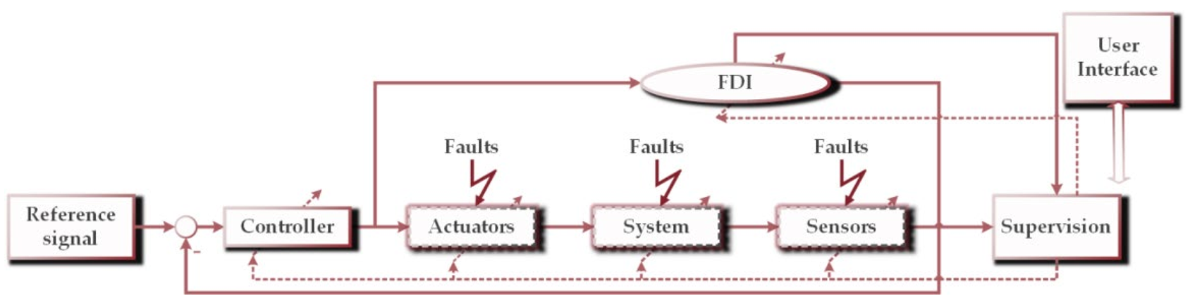
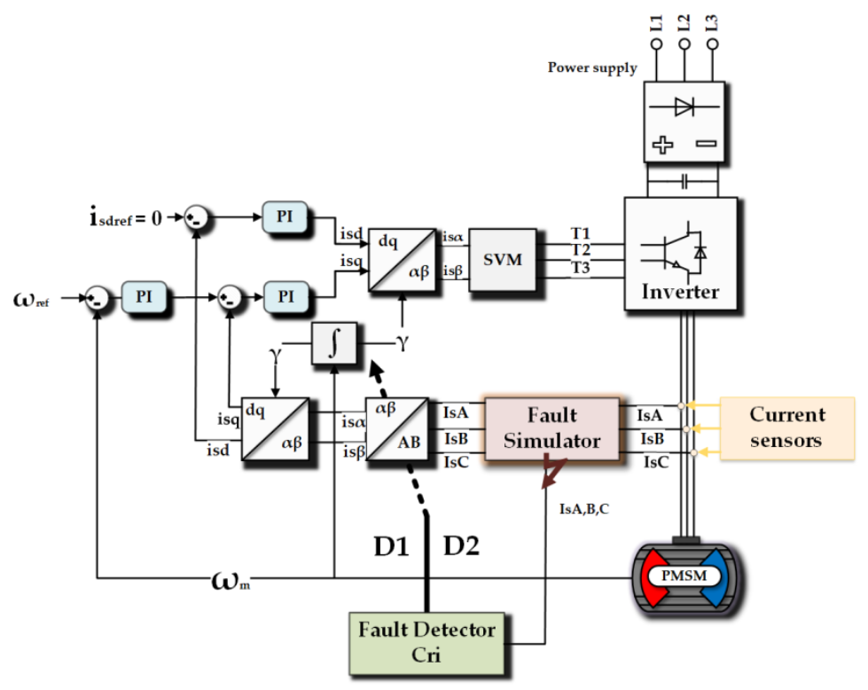
5. Fault Tolerant Control Structure with Analytical Detection and Compensation System

In this part of the paper, the analysis of the fault tolerant control structure with the proposed detection and compensation algorithm is presented. The analysis was performed for the field-oriented control structure presented in Figure 15. As it was mentioned, for the proper operation of this FTC system, three current sensors are necessary. For the normal operation, only two of them are used. The third is redundant equipment.
The compensation algorithm is required only in the control structure with current feedback to provide appropriate work conditions. The results of the detection and compensation algorithm under different speed values in FOC control are presented in Figure 16 and Figure 17. When a fault occurs, the algorithm immediately detects and localizes it, then the system is reconfigured to calculate the α, β components, using the additional current sensor in phase C, which results in undisturbed speed transient.
Figure 16 shows that at 0.4 s a failure occurs and it is detected after several time samples. The compensation algorithm converts the damaged sensor from phase A (or B) to the healthy sensor from phase C. It can be seen that the D1 and D2 signals immediately change their value from zero to 1, which indicates that a failure was detected. Compensation shows that the failed sensor is not used in the internal control structure. The drive works properly. Contrary to the system without compensation, the speed does not show oscillation and in the current components there are no oscillations that could lead to the demagnetization of the rotor.
The obtained results allow us to conclude that the analysed algorithm is able to detect a current sensor fault and identify a faulty phase. Without fault localization, compensation using insensitive components is impossible, which is visible in Figure 16c. When incorrect identification occurs it causes insufficient compensation.

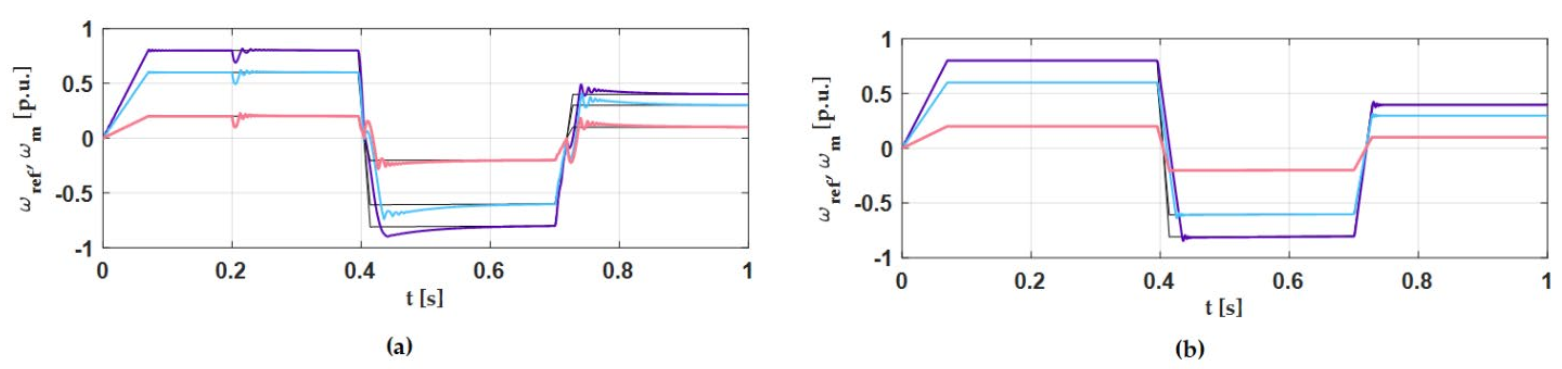
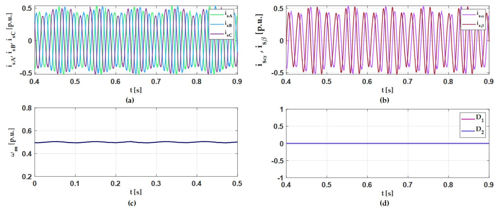
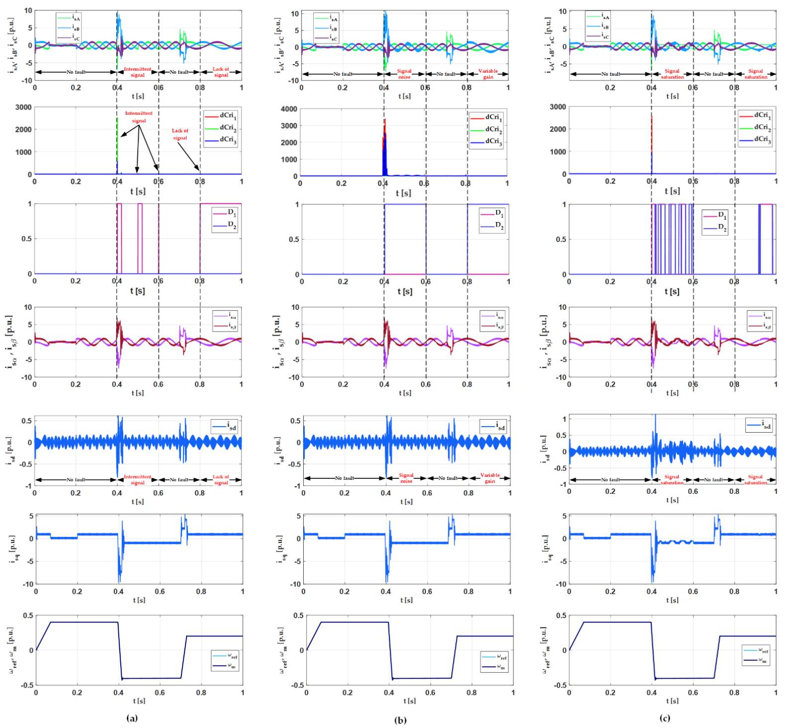
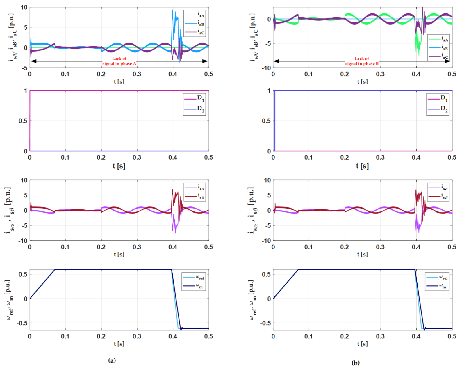
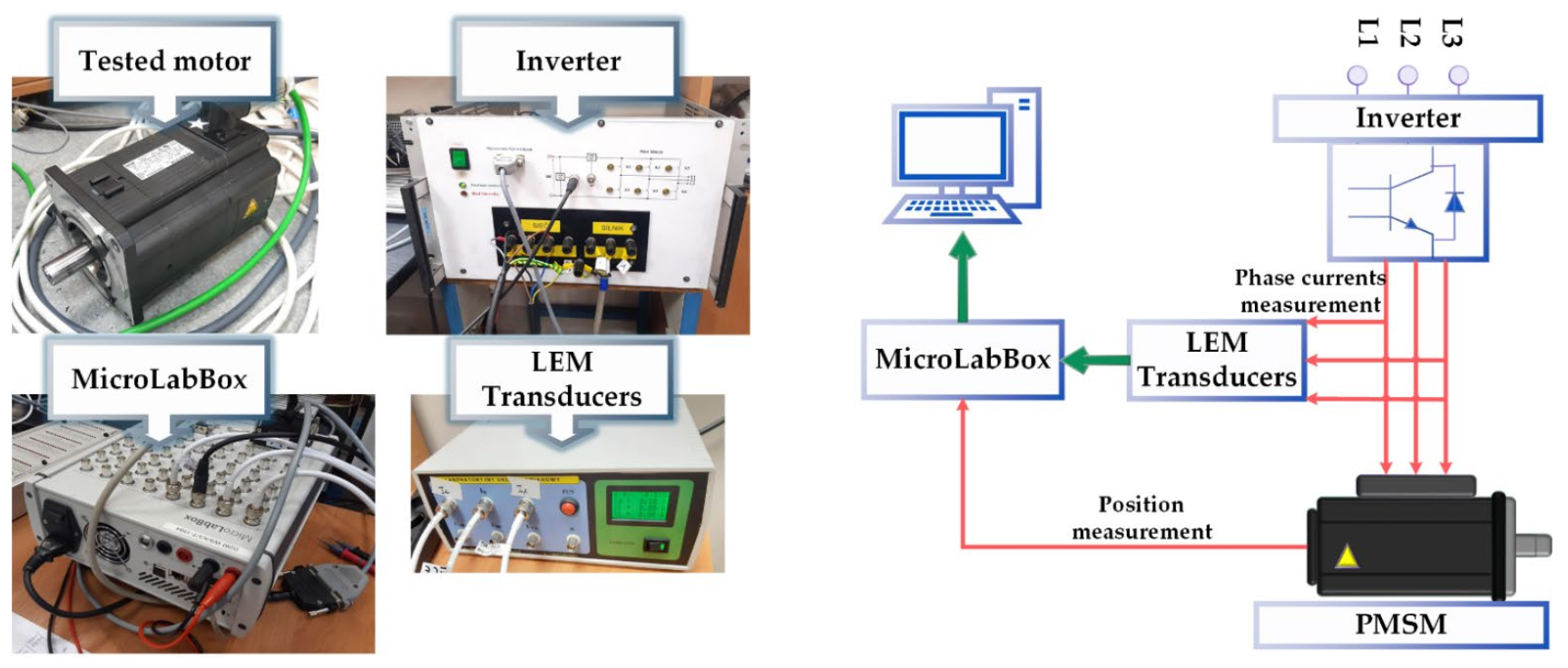
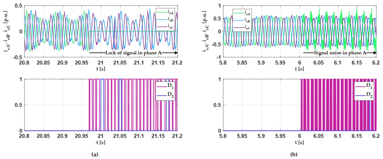
6. Experimental Results

Detection algorithm also was tested on the laboratory set-up, presented on Figure 18. In Table 4 the PMSM parameters used in the experiments are shown. Experiment were conducted in scalar control using dSpace 1202 Microlabox. Fault detection was tested for the same faults presented and analysed in the simulations.
In the first experimental figure (Figure 19) the analysis of the control structure with the healthy sensors is presented. It is visible that drive works stably. Rotor speed is equal with the reference frame. Some oscillations on the stator currents are visible.
In the next part of this section the influence of the stator current sensor faults to the properties of the drive and detection system is presented. The main goal of this analysis is to show that it is possible to detect in a short time all sensor faults. It was shown also that detection and compensation algorithm can replace a broken sensor for the healthy one. Transients of faulted phases and detector responses are presented on Figure 20 and Figure 21.
It is visible during the first two steps that the detection algorithm detects the fault conditions. In those two steps a fault is detected and information for the compensation algorithm is sent. After fault detection it is visible that character of the detection signal is a repeating impulse. From the point of view of the detection the most important is the first short period of detection signal. It is obvious that after fault detection in one phase, the current sensor from this phase cannot be used anymore in the control structure, as the detector response even goes to zero.
The detector responses under the experimental conditions are consistent with the simulation. During intermittent signal in phase A, output D1 is set to 1 only when a signal is intermittent. The detector also recognizes a faulty phase correctly. Even during a less significant failure, the detection process is working properly.

7. Conclusions

The article presented an algorithm for the detection and compensation of damage to stator current sensors in the vector control system of PMSM drives. Tests were presented for a system without feedback from measuring sensors, in order to illustrate the operation of the fault detector and the full FOC system. A complete FTC algorithm has been proposed to allow the safe operation of the drives.
The analysis of scalar control allows us to present the impact of individual faults on current components used in FOC without distortion from another phase. The results show that most of the mentioned faults can be correctly detected under both scalar and vector control conditions at any time, even when the fault occurs before start-up. During signal saturation, the detector makes a mistake in/related to the indication of the property phase, however, a fault is always detected without any false alarm. Regularity that can be observed in detector mistakes provides a direction for improving the algorithm. The results from DFOC show that a properly detected and localized fault may be compensated under different speed values, also when the fault appears before start-up, using the implemented algorithm. Its simplicity makes it computationally interesting and possible to implement in a signal processor. After simulation verification, the effectiveness of the detectors has been confirmed experimentally. The experimental results are compatible with the simulations. In future work a full FTC system will be tested and analysed.

Author Contributions

Conceptualization, M.D., K.J.; methodology, M.D., K.J.; software, K.J.; validation, M.D., K.J.; formal analysis, M.D., K.J.; investigation, M.D., K.J.; resources, M.D., K.J.; data curation, K.J.; writing—original draft preparation, K.J.; writing—review and editing, M.D.; visualization, K.J.; supervision, M.D.; project administration, M.D.; funding acquisition, M.D. All authors have read and agreed to the published version of the manuscript.

Funding

This research received no external funding.

Institutional Review Board Statement

Not applicable.

Informed Consent Statement

Not applicable.

Data Availability Statement

Not applicable.

Acknowledgments

This research was supported by statutory funds of the Faculty of Electrical Engineering, Wroclaw University of Science and Technology (2021).

Conflicts of Interest

The authors declare no conflict of interest.

References

  1. Shen, Q.; Yue, C.; Goh, C.H.; Wang, D. Active Fault-Tolerant Control System Design for Spacecraft Attitude Maneuvers with Actuator Saturation and Faults. IEEE Trans. Ind. Electron. 2019, 66, 3763–3772. [Google Scholar] [CrossRef]
  2. Klimkowski, K.; Dybkowski, M. A Fault Tolerant Control Structure for an Induction Motor Drive System. Automatika 2016, 57, 638–647. [Google Scholar] [CrossRef]
  3. Guezmil, A.; Berriri, H.; Pusca, R.; Sakly, A.; Romary, R.; Mimouni, M.F. Experimental Investigation of Passive Fault Tolerant Control for Induction Machine Using Sliding Mode Approach. Asian J. Control 2019, 21, 520–532. [Google Scholar] [CrossRef] [Green Version]
  4. Guezmil, A.; Berriri, H.; Sakly, A.; Mimouni, M.F. Sliding Mode-Based Active Fault-Tolerant Control for Induction Machine. Arab. J. Sci. Eng. 2020, 45, 1447–1455. [Google Scholar] [CrossRef]
  5. Jlassi, I.; Cardoso, A.J.M. A Single Method for Multiple IGBT, Current, and Speed Sensor Faults Diagnosis in Regenerative PMSM Drives. IEEE J. Emerg. Sel. Top. Power Electron. 2020, 8, 2583–2599. [Google Scholar] [CrossRef]
  6. Li, H.; Qian, Y.; Asgarpoor, S.; Sharif, H. PMSM Current Sensor FDI Based on DC Link Current Estimation. In Proceedings of the IEEE 88th Vehicular Technology Conference (VTC-Fall), Chicago, IL, USA, 27–30 August 2018; pp. 1–5. [Google Scholar] [CrossRef]
  7. Huang, G.; Luo, Y.-P.; Zhang, C.-F.; He, J.; Huang, Y.-S. Current Sensor Fault Reconstruction for PMSM Drives. Sensors 2016, 16, 178. [Google Scholar] [CrossRef]
  8. Adamczyk, M.; Orlowska-Kowalska, T. Virtual Current Sensor in the Fault-Tolerant Field-Oriented Control Structure of an Induction Motor Drive. Sensors 2019, 19, 4979. [Google Scholar] [CrossRef] [Green Version]
  9. Yu, Y.; Zhao, Y.; Wang, B.; Huang, X.; Xu, D. Current Sensor Fault Diagnosis and Tolerant Control for VSI-Based Induction Motor Drives. IEEE Trans. Power Electron. 2018, 33, 4238–4248. [Google Scholar] [CrossRef]
  10. Chakraborty, C.; Verma, V. Speed and Current Sensor Fault Detection and Isolation Technique for Induction Motor Drive Using Axes Transformation. IEEE Trans. Ind. Electron. 2015, 62, 1943–1954. [Google Scholar] [CrossRef]
  11. Wu, C.; Guo, C.; Xie, Z.; Ni, F.; Liu, H. A Signal-Based Fault Detection and Tolerance Control Method of Current Sensor for PMSM Drive. IEEE Trans. Ind. Electron. 2018, 65, 9646–9657. [Google Scholar] [CrossRef]
  12. Wang, G.; Hao, X.; Zhao, N.; Zhang, G.; Xu, D. Current Sensor Fault-Tolerant Control Strategy for Encoderless PMSM Drives Based on Single Sliding Mode Observer. IEEE Trans. Transp. Electrif. 2020, 6, 679–689. [Google Scholar] [CrossRef]
  13. Huang, G.; She, J.; Fukushima, E.F.; Zhang, C.; He, J. Robust Reconstruction of Current Sensor Faults for PMSM Drives in the Presence of Disturbances. IEEE/ASME Trans. Mechatron. 2019, 24, 2919–2930. [Google Scholar] [CrossRef]
  14. Kommuri, S.K.; Defoort, M.; Karimi, H.R.; Veluvolu, K.C. A Robust Observer-Based Sensor Fault-Tolerant Control for PMSM in Electric Vehicles. IEEE Trans. Ind. Electron. 2016, 63, 7671–7681. [Google Scholar] [CrossRef]
  15. Dybkowski, M.; Klimkowski, K. Artificial Neural Network Application for Current Sensors Fault Detection in the Vector Controlled Induction Motor Drive. Sensors 2019, 19, 571. [Google Scholar] [CrossRef] [Green Version]
  16. Amin, A.A.; Hasan, K.M. A review of Fault Tolerant Control Systems: Advancements and applications. Measurement 2019, 143, 58–68. [Google Scholar] [CrossRef]
  17. Ku, H.K.; Jung, J.H.; Park, J.W.; Kim, J.M.; Son, Y.D. Fault-tolerant control strategy for open-circuit fault of two-parallel-connected three-phase AC–DC two-level PWM converter. J. Power Electron. 2020, 20, 731–742. [Google Scholar] [CrossRef]
  18. Mossa, M.A.; Echeikh, H.; Diab, A.A.Z.; Alhelou, H.H.; Siano, P. Comparative Study of Hysteresis Controller, Resonant Controller and Direct Torque Control of Five-Phase IM under Open-Phase Fault Operation. Energies 2021, 14, 1317. [Google Scholar] [CrossRef]
  19. Chen, T.; Pan, Y.; Xiong, Z. A Hybrid System Model-Based Open-Circuit Fault Diagnosis Method of Three-Phase Voltage-Source Inverters for PMSM Drive Systems. Electronics 2020, 9, 1251. [Google Scholar] [CrossRef]
  20. Ewert, P.; Orlowska-Kowalska, T.; Jankowska, K. Effectiveness Analysis of PMSM Motor Rolling Bearing Fault Detectors Based on Vibration Analysis and Shallow Neural Networks. Energies 2021, 14, 712. [Google Scholar] [CrossRef]
  21. Ewert, P. The Application of the Bispectrum Analysis to Detect the Rotor Unbalance of the Induction Motor Supplied by the Mains and Frequency Converter. Energies 2020, 13, 3009. [Google Scholar] [CrossRef]
  22. Jiang, J.; Yu, X. Fault-tolerant control systems: A comparative study between active and passive approaches. Annu. Rev. Control 2012, 36, 60–72. [Google Scholar] [CrossRef]
  23. Toma, R.N.; Prosvirin, A.E.; Kim, J.-M. Bearing Fault Diagnosis of Induction Motors Using a Genetic Algorithm and Machine Learning Classifiers. Sensors 2020, 20, 1884. [Google Scholar] [CrossRef] [Green Version]
  24. Pietrzak, P.; Wolkiewicz, M. Comparison of Selected Methods for the Stator Winding Condition Monitoring of a PMSM Using the Stator Phase Currents. Energies 2021, 14, 1630. [Google Scholar] [CrossRef]
  25. Skowron, M.; Orlowska-Kowalska, T.; Wolkiewicz, M.; Kowalski, C.T. Convolutional Neural Network-Based Stator Current Data-Driven Incipient Stator Fault Diagnosis of Inverter-Fed Induction Motor. Energies 2020, 13, 1475. [Google Scholar] [CrossRef] [Green Version]
  26. Skowron, M.; Wolkiewicz, M.; Tarchała, G. Stator winding fault diagnosis of induction motor operating under the field-oriented control with convolutional neural networks. Bull. Pol. Acad. Sci. Tech. Sci. 2020, 68. [Google Scholar] [CrossRef]
  27. Isermann, R. Fault-Diagnosis Applications, Model-Based Condition Monitoring: Actuators, Drives, Machinery, Plants, Sensors, and Fault-Tolerant Systems; Springer: Berlin, Germany, 2011. [Google Scholar]
  28. Adouni, A.; Hamed, M.B.; Flah, A.; Sbita, L. Sensor and actuator fault detection and isolation based on artificial neural networks and fuzzy logic applicated on Induction motor. In Proceedings of the International Conference on Control, Decision and Information Technologies (CoDIT), Hammamet, Tunisia, 6–8 May 2013. [Google Scholar]
  29. Rothenhagen, K.; Fuchs, F.W. Model-based fault detection of gain and offset faults in doubly fed Induction generators. In Proceedings of the IEEE International symposium on diagnostics for Electric Machines, Power Electronics and Drives (SDEMPED), Cargese, France, 31 August–3 September 2009. [Google Scholar]
  30. Gao, Y.; Wu, Y.; Wang, X.; Chen, Q. Characteristic model-based adaptive fault-tolerant control for four-PMSM synchronization system. Proc. Inst. Mech. Eng. Part I J. Syst. Control Eng. 2021, 235, 680–691. [Google Scholar] [CrossRef]
  31. Gao, Z.; Cecati, C.; Ding, S.X. A survey of fault diagnosis and fault-tolerant techniques—Part I: Fault diagnosis with model-based and signal-based approaches. IEEE Trans. Ind. Electron. 2015, 62, 3757–3767. [Google Scholar] [CrossRef] [Green Version]
  32. Klimkowski, K.; Dybkowski, M. Adaptive fault tolerant direct torque control structure of the induction motor drive. In Proceedings of the International Conference on Electrical Drives and Power Electronics (EDPE), Tatranska Lomnica, Slovakia, 21–23 September 2015; pp. 7–12. [Google Scholar] [CrossRef]
  33. Beddek, K.; Merabet, A.; Kesraoui, M.; Tanvir, A.A.; Beguenane, R. Signal-Based Sensor Fault Detection and Isolation for PMSG in Wind Energy Conversion Systems. IEEE Trans. Instrum. Meas. 2017, 66, 2403–2412. [Google Scholar] [CrossRef]
  34. Li, Z.; Wheeler, P.; Watson, A.; Costabeber, A.; Wang, B.; Ren, Y.; Bai, Z.; Ma, H. A Fast Diagnosis Method for Both IGBT Faults and Current Sensor Faults in Grid-Tied Three-Phase Inverters with Two Current Sensors. IEEE Trans. Power Electron. 2020, 35, 5267–5278. [Google Scholar] [CrossRef]
  35. Bahri, I.; Naouar, M.; Slama-Belkhodja, I.; Monmasson, E. FPGA-Based FDI of Faulty Current Sensor in Current Controlled PWM Converters. In Proceedings of the EUROCON 2007—The International Conference on “Computer as a Tool”, Warsaw, Poland, 9–12 September 2007; pp. 1679–1686. [Google Scholar] [CrossRef]
  36. Dybkowski, M.; Klimkowski, K. Stator current sensor fault detection and isolation for vector controlled induction motor drive. In Proceedings of the IEEE International Power Electronics and Motion Control Conference (PEMC), Varna, Bulgaria, 25–28 September 2016; pp. 1097–1102. [Google Scholar] [CrossRef]
  37. Krzysztofiak, M.; Skowron, M.; Orlowska-Kowalska, T. Analysis of the Impact of Stator Inter-Turn Short Circuits on PMSM Drive with Scalar and Vector Control. Energies 2021, 14, 153. [Google Scholar] [CrossRef]
  38. Montesinos-Miracle, D.; Perera, P.C.; Galceran-Arellano, S.; Blaabjerg, F.; Casolo, F. Sensorless V/f Control of Permanent Magnet Synchronous Motors. In Motion Control; IntechOpen: Rijeka, Croatia, 2010; pp. 439–458. [Google Scholar]
  39. Ali, M.Z.; Shabbir, M.N.S.K.; Zaman, S.M.K.; Liang, X. Single- and Multi-Fault Diagnosis Using Machine Learning for Variable Frequency Drive-Fed Induction Motors. IEEE Trans. Ind. Appl. 2020, 56, 2324–2337. [Google Scholar] [CrossRef]
  40. Dini, P.; Saponara, S. Cogging torque reduction in brushless motors by a nonlinear control technique. Energies 2019, 12, 2224. [Google Scholar] [CrossRef] [Green Version]
  41. Dini, P.; Saponara, S. Design of an Observer-Based Architecture and Non-Linear Control Algorithm for Cogging Torque Reduction in Synchronous Motors. Energies 2020, 13, 2077. [Google Scholar] [CrossRef]
Figure 1. General diagram of a fault tolerant control system.
Energies 14 03443 g001
Figure 2. General diagram of scalar control system (a) and field-oriented control (b) with space vector modulation (SVM), where i s A , i s B , i s C —phase currents, i s α , i s β —stator current components, i s d , i s q —stator currents components in rotor frame.
Energies 14 03443 g002
Figure 3. Speed transients for a few different reference values in scalar control (a) and field-oriented control (b).
Energies 14 03443 g003
Figure 4. Influence of lack of signal (a,c,e,g) and intermittent signal (b,d,f,h) on phase currents i s A , i s B , i s C (a,b), stator current components i s α , i s β (c,d), currents i s d , i s q (e,f,g,h) in the scalar control structure.
Energies 14 03443 g004
Figure 5. Influence of signal noise (a,d,g,j), variable gain (b,e,h,k), signal saturation on phase currents (c,f,i,l) on phase currents i s A , i s B , i s C (a,b,c), stator current components i s α , i s β (d,e,f), currents i s d , i s q (g,h,i,j,k,l) in the scalar control structure.
Energies 14 03443 g005
Figure 6. Influence of lack of signal on speed transient in phase A (a) and B (b), phase currents, currents i s A , i s B , i s C in phase A (c) and B (d), stator current components i s α , i s β in phase A (e) and B (f) and currents i s d , i s q in phase A (g,i) and B (h,j) in the FOC drive.
Energies 14 03443 g006
Figure 7. Influence of intermittent signal on speed transients in phase A (a) and B (b), phase currents, currents i s A , i s B , i s C in phase A (c) and B (d), stator current components i s α , i s β in phase A (e) and B (f) and currents i s d , i s q in phase A (g,i) and B (h,j) in the FOC drive.
Energies 14 03443 g007
Figure 8. General diagram of current sensor fault detector algorithm.
Energies 14 03443 g008
Figure 9. Marker transients in phase A under lack of signal (b), intermittent signal (d), variable gain (f) and their errors, respectively (a,c,e) in scalar control.
Energies 14 03443 g009
Figure 10. Marker transients in phase B under lack of signal (b), intermittent signal (d), variable gain (f) and their errors, respectively (a,c,e) in scalar control.
Energies 14 03443 g010
Figure 11. Phase currents under lack of signal and intermittent signal fault in phase A (a), B (b) and detector responses in scalar control structure for ω r e f = 0.6 ω N .
Energies 14 03443 g011
Figure 12. Phase currents under signal noise and variable gain ( 1.2 i s m ) fault in phase A (a), B (b) and detector responses in scalar control structure for ω r e f = 0.6 ω N .
Energies 14 03443 g012
Figure 13. Phase currents under signal saturation in phase A (a), B (b) and detector responses in scalar control structure.
Energies 14 03443 g013
Figure 14. General diagram of current sensor fault compensation algorithm.
Energies 14 03443 g014
Figure 15. General diagram of field oriented control structure with fault detector.
Energies 14 03443 g015
Figure 16. Transients of basic variables: phase currents, markers errors, detector responses, current components α, β, i s d , i s q current components and speed under lack of signal and intermittent signal in phase A (a), signal noise and variable gain (b), signal saturation (c), respectively.
Energies 14 03443 g016
Figure 17. Transients of basic variables under start-up with lack of signal and its compensation in phase A (a) and B (b) respectively phase currents, detector responses, current components α, β and speed.
Energies 14 03443 g017
Figure 18. Photos and general diagram of experimental set-up.
Energies 14 03443 g018
Figure 19. Transients of basic variables: phase currents (a), current components α, β (b), speed (c), detector responses (d) under healthy conditions on experimental set-up.
Energies 14 03443 g019
Figure 20. Phase currents underlack of signal (a) and signal noise (b) in phase A and detector responses in scalar control structure on experimental set-up.
Energies 14 03443 g020
Figure 21. Phase currents under intermittent signal (a) and variable gain (b) in phase B and detector responses in scalar control structure on experimental set-up.
Energies 14 03443 g021
Table 1. Parameters of motor used in simulations.
PN
[kW]
Stator Phase
Resistance
[Ω]
Stator Phase
Inductance
[mH]
Pp
[–]
nN
[rpm]
Inertia
[kg·m2]
Viscous Damping
[N·m·s]
Flux Linkage
Established by Magnets
[Wb]
2.55.564.11215000.0151000.8
Table 2. Typical fault types of the current sensor.
Type of the FaultCurrent Value
Variable gain i s m =   1 γ i a
Phase shift i s m = i a + i o f f s e t
Signal limit i s m = i s a t
Noise i s m = i a + n t
Lack of signal i s m = 0
Intermittent signal i s m =   0 , 1
where: ism—measured current, ia—real current, n(t)—white noise, γ—constant value from the range <−1, 1>, isat—limited current, ioffset = 10 Hz phase shift, A—current amplitude.
Table 3. Dependencies between markers under different phase faults.
Type of FaultΔCrij
No faultΔCri1 = ΔCri2 = ΔCri3
Phase A sensorΔCri1 < ΔCri3 < ΔCri2
Phase B sensorΔCri2 < ΔCri3 < ΔCri1
Table 4. Parameters of the tested motor.
PN
[kW]
IN
[A]
UN
[V]
PpnN
[rpm]
TN
[Nm]
Fs
[Hz]
2.56.63254150021100
Publisher’s Note: MDPI stays neutral with regard to jurisdictional claims in published maps and institutional affiliations.

