Abstract
In this work, Ni0.5Zn0.5Fe2O4 is synthesized as binder-based (NZF) and binder-free electrodes (NZF@NF). The binder-free electrode is directly synthesized on nickel foam via facile hydrothermal techniques. The crystalline phase of both of these electrodes is examined through X-ray diffraction. Their morphology is investigated by scanning electron microscopy (SEM) and high-resolution transmission electron microscopy (TEM), which revealed the well-defined nanostructure with the shape like thin hexagonal platelets. The chemical composition is verified by energy dispersive spectroscopy (EDS). Their electrochemical properties are analyzed by cyclic voltammetry (CV), galvanostatic charge–discharge (GCD), and electrochemical impedance spectroscopy (EIS). The NZF@NF electrode has outperformed the binder-based NZF electrode in terms of electrochemical performance owing to the 3D interconnected structure of the nickel foam. The NZF@NF electrode has delivered a high specific capacity of 504 F g−1 at the current density of 1 A g−1, while its counterpart has delivered a specific capacity of 151 F g−1 at the same current density.
1. Introduction
The world economy is growing at an exponential rate with huge demand for energy conversion and energy storage systems. Fossil fuel reserves are dwindling with high emissions of greenhouse gasses, leaving indelible scars on the global ecosystem. So, it is the need of the hour to develop clean, nonrenewable energy sources along with energy storage systems. Energy storage systems, such as batteries, fuel cells, and supercapacitors, can solve the dilemma of efficient energy storage [1,2,3]. Among these devices, supercapacitors are desirable owing to their high-power density, rapid charge–discharge, cycling stability, and cheap fabrication cost. Moreover, the supercapacitors have found their niche in electric vehicles, portable electronic devices, and backup power supply of numerous devices, ranging from military and medical equipment to household items.
In a supercapacitor, the charge storage mechanism is divided into two main categories, namely, electrochemical double-layer capacitors (EDLCs) and pseudocapacitors [1,4,5,6]. The carbon-based materials follow an electrostatic EDLC mechanism. The charge storage mechanism of the metallic oxides is a pseudocapacitive and is based on a faradic process [7]. The transition metals are alluring choices as the electrode materials in supercapacitors owing to their reversible redox reaction happening at a faster pace due to the pseudocapacitive transfer of ions and electrons in the electrochemical reactions. Ruthenium has a high theoretical specific capacity among all transition metals, but its toxicity and cost barred its potential commercial applications. Transition metals, such as zinc, nickel, cobalt, and manganese, are good alternatives but still require attention to improve their low electrical conductivity and stability.
So, in a bid to improve the shortfalls of transition metals, mixed metallic oxides are extensively investigated, such as Mn/Co, Mn/Fe, or Ni/Co, etc. These mixed metallic oxides have achieved amazing success in electrochemical arenas. The mixed metallic oxides, such as spinel ferrites, are desirable because of their multiple redox sites, electrical and optical properties, and stability during electrochemical conversion [8,9]. The general formula for the spinel ferrites are MF2O4 (M = transition metals such as Ni, Co, or Mn) with the ferric ions having an octahedral position and the metal ions are at the tetrahedral sites [10]. It is believed that the spinel ferrites will demonstrate a richer redox chemistry due to the contribution from the M and Fe ions than the single metallic oxides in electrochemical reactions. Many ferrites with nickel and cobalt have demonstrated their superior electrochemical properties due to the multiple vacancies of the divalent transition metal ions. This contribution of the metallic cations makes them catalytically active on the electrode surface, which improves the electrochemical properties. So, the addition of more divalent ions in the spinel ferrites will significantly enhance the electrochemical properties of these spinel ferrites and can uplift the energy density of the energy storage devices.
Many spinel ferrites, such as CoFe2O4, NiFe2O4, and ZnFe2O4, have demonstrated their superior electrochemical performance due to their rich electrochemical redox chemistry. Bablu Mordina et al. [11] has synthesized a binder-free NiFe2O4 electrode on a nickel foam substrate and stainless-steel substrate. The nickel foam substrate has outperformed the stainless-steel substrate due to its porous structure by achieving a value of specific capacity as high as 398 C g−1 at 1 A g−1. In another work, single-phase spinel ternary transition ferrite nanocomposites, such as CuCoFe2O4, NiCoFe2O4 and NiCuFe2O4, were synthesized [12]. Among these ternary transition ferrites, CuCoFe2O4 has demonstrated enhanced electrochemical activity, and a value of specific capacitance of 221 F g−1 at a scan rate of 1 A g−1 was achieved, with excellent cycling stability. The high electrochemical performance of these ternary transition ferrite nanocomposites indicates that these materials are promising electrodes for supercapacitors.
The specific capacitance of the transition metallic ferrites can be enhanced by the incorporation of the conducting polymers and reduced graphene oxide in the structural matrix. Highly conductive surfaces, such as reduced graphene oxide, can provide channels for faster and facile diffusion of the charge carriers with increased conductivity and specific surface area. On the other hand, the ferrite nanoparticles on the surface of the reduced graphene oxide can prevent the restacking of the reduced graphene oxide sheets. Similar studies have been carried out in which introduction of reduced graphene oxide has increased the specific capacitance of these ferrite materials, i.e., NiFe2O4 [13], ZnFe2O4 [14], Mn1-xCuxFe2O4 [15], and PEDOT:PSS-wrapped NiFe2O4 [16].
Metallic oxides such as ferrites have a large surface area with facile diffusion for the electron-ion. Still, these metallic oxides suffer from poor electric conductivity and higher contact resistance in binder-based electrodes. The polymers used for adhesion of the active material on the electrode results in a dead surface, thus severely limiting their electrochemical performance. The direct synthesis of ferrite nanomaterials on substrates such as carbon paper, carbon fabric, or nickel foam was found to be an effective strategy for enhancing the electrochemical activity [2,17,18,19,20]. Nickel foam as a current collector has several advantages necessary for high-performance devices, such as efficient electron transfer, high physical strength, and a 3D macroporous structure [21].
Malaie et al. [22] has demonstrated that the magnesium ferrite nano-flowers hydrothermally grown on nickel foam has an exceptional supercapacitance of 241 F g−1 at a scan rate of 20 mVs−1. An increase in aerial capacitance and decrease in serial resistance is observed after 2000 cycles, which is due to further activation of the magnesium ferrite nano-flowers on the surface of the nickel foam. In a similar study [23], the facile hydrothermal method was employed to create binder-free electrodes of Ni(OH)2/NiFe2O4 with various molarity of the Fe(NO3)3. The specific capacitance of Ni(OH)2/NiFe2O4 was greater than the bare Ni(OH)2 and NiFe2O4 binder-free electrodes, due to a synergetic combination between Ni(OH)2 and NiFe2O4. In turn, the molarity of 1 mmol F(NO3)3 was found to be optimum with larger CV curves and less agglomeration of the particles on the surface of the nickel foam.
The spinel ferrites can be synthesized by co-precipitation, solvothermal, and hydrothermal methods, but the hydrothermal technique has proven to be the most effective one [24]. In this work, we have synthesized Ni0.5Zn0.5Fe2O4 nanomaterials as an active material for supercapacitor application and also directly synthesized Ni0.5Zn0.5Fe2O4 on highly conducting nickel foam. The electrochemical properties of binder-based and binder-free electrodes are compared using CV, galvanostatic charge–discharge, and EIS.
2. Synthesis Process
The synthesis process is elaborated in Scheme 1.
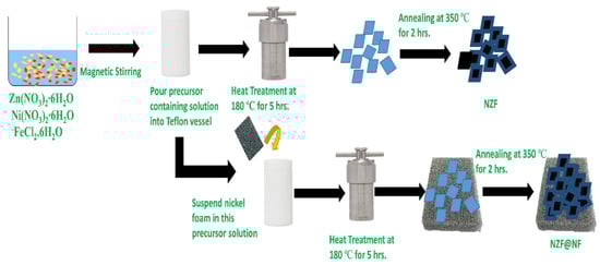
Scheme 1.
Synthesis route for NZF and NZF@NF.
2.1. Materials
All materials, such as the Zn(NO3)2∙6H2O, Ni(NO3)2∙6H2O, FeCl2∙6H2O, ammonium fluoride (NH4F), and urea (CH4N2O) were purchased from Sigma Aldrich. All materials are >98 percent pure and used without any further modification. The nickel foam used in this study has a thickness of 2 mm with 110PPI.
2.2. Treatment of the Nickel Foam
First of all, nickel foam of size 2 × 2 cm2 was cut, then treated with 2M HCl solution in a sonication bath for 30 min to remove the oxidation layer. Later, the nickel foam piece was cleaned with ethanol and distilled water to remove the impurities, followed by drying overnight at 80 °C.
2.3. Synthesis of the Nickel Zinc Ferrite
In 70 mL deionized water, 0.005 M Zn(NO3)2∙6H2O was added. Then 0.005 M Ni(NO3)2∙6H2O and 0.02 M FeCl2.6H2O were added. Followed by the addition of 0.02 M ammonium fluoride (NH4F) and 0.05 M urea in the prepared solution to start the co-precipitates. This solution with the precursors was put on a magnetic stirrer for half an hour to form a greenish brown solution. After forming a solution with all reagents dissolved in it was put into a 100 mL autoclave. The autoclave was sealed tightly and placed in an oven for 180 °C for 5 h and then allowed to cool down at room temperature after completing the reaction. Later the precipitates were centrifuged and washed with distilled water and ethanol repeatedly to clear it from all the loosened impurities. Later these were dried overnight at 80 °C and subsequently annealed at 350 °C for 2 h. The prepared sample was labeled as NZF.
2.4. Synthesis of Binder-Free Nickel Zinc Ferrite
Pre-cleaned nickel foam was put in the above solution with all precursors to prepare the binder-free electrode. The nickel foam was suspended in the autoclave with the help of a polyfluortetraethylene (PTFE) thread to ensure homogeneous coating. This nickel foam-containing solution was maintained at 180 °C for 5 h. Later, the nickel foam was washed in an ultrasonic bath with deionized water and ethanol to clear it from all the loosened impurities. The nickel foam was dried overnight and later annealed at 350 °C for 2 h. This binder-free electrode with active mass loading was labeled as NZF@NF.
2.5. Characterizations
The structural purity of the prepared sample was analyzed by X-ray diffraction (XRD) via a Bruker X-ray diffractometer (Cu Kα radiation). The value of two theta was varied a from 10° to 80°, with a counting time of 0.5 s and using a step size of 0.02°. SEM (EVO50 ZEISS) was used to study the surface properties of the electrode
2.6. Electrochemical Measurements
The 3M KOH solution was employed as the electrolyte in the three electrodes’ electrochemical cells. In the binder-free electrode cell, the platinum foil (Pt) electrode was the counter electrode and the saturated calomel electrode (SCE) was the reference electrode, while the nickel foams with material loading were used as the working electrode. The area of the prepared nickel foam electrode was 2 × 2 cm2. The binder-based working electrode was prepared with a mass ratio of 8:1:1 with NZF-synthesized samples, acetylene black (BP2000), and polyfluortetraethylene (PTFE), respectively. The electrochemical activity of the prepared electrodes was analyzed on an electrochemical workstation (CHI 660e) using the CV and galvanostatic charge–discharge measurements. At an open circuit, potential EIS measurements were done by using an AC voltage with 5 mV amplitude while the values of the frequency varied from 0.01 Hz to 100 kHz.
3. Results and Discussions
In Figure 1, the XRD peak patterns of NZF and NZF@NF are displayed. The observed XRD peaks at 2θ of 18.12°, 30.06°, 35.32°, 37.04°, 43.02°, 53.45°, 57.0°, and 62.63° can be assigned to (111), (220), (311), (222), (400), (422), (511), (440), and (433) miller indexes, respectively. The strong XRD peaks at 44.50°, 51.78°, and 76.32° can be ascribed to the diffraction at the (111), (200), and (222) crystal planes of the nickel foam, respectively. In the prepared samples, all the characteristic peaks for the ferrite materials are present along with the most intense peak at (311), which confirms the formation of a cubic spinel structure.
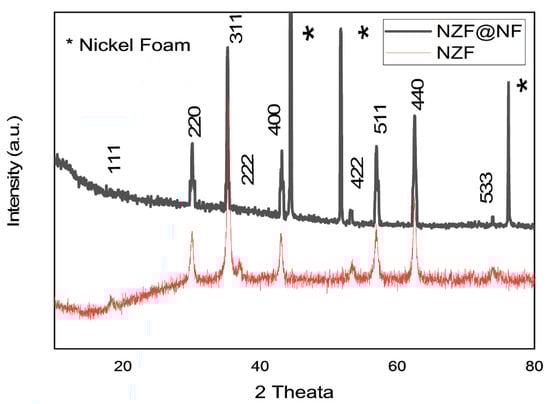
Figure 1.
X-ray diffraction of NZF and NZF@NF.
A considerable broadening of the peaks is observed due to the presence of the crystalline size of the nanomaterial in both the NZF and NZF@NF electrodes. So, in the wake of such broadening of peaks, the Scherer formula was used to find the size of the nanomaterials. The size of the nanomaterial was found to be 33.7 nm by applying the Scherer formula based on the full width half maximum (FWHM) of the (311) high intensity peak, as given in Equation (1). The obtained peaks are in good agreement with the reported literature [25,26]. The average crystallite of the nanoparticles was calculated using the Scherer formula.
where λ is the wavelength of the X-ray in nanometer, θ is the Bragg’s angle in degree, and β is the full angular line width in radian at the half maximum intensity.
To clarify the morphology of the nickel zinc ferrite (NZF) with and without nickel foam, the FESEM technique was employed, as shown in Figure 2a–d. In comparison, in NZF@NF (Figure 2c,d), the particles are clearly segregated with less agglomeration. The 3D structure of the Ni foam is an effective substrate that can provide pathways for active materials to penetrate the electrolyte easily. In particular, it prevents the clustering of the nanoparticles. Energy dispersive spectroscopy was used to examine the chemical composition of the prepared samples, as displayed in Figure 3a,b. The presence of the Ni, Zn, Fe, and O peaks depicts the presence of nickel, zinc, iron, and oxygen in the prepared samples.
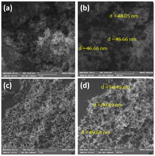
Figure 2.
FESEM images of (a,b) NZF (c,d) and NZF@NF.
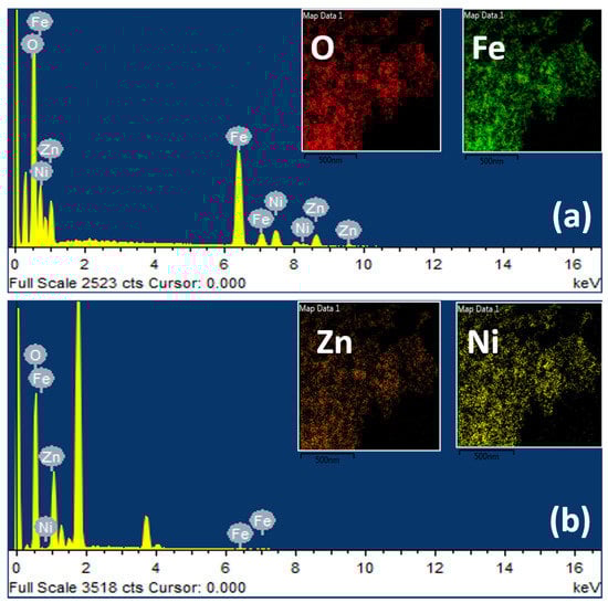
Figure 3.
EDS spectra of (a) NZF@NF (b) and NZF.
Figure 4a,b shows thin hexagonal platelets like the morphology of both the NZF and NZF@NF samples, which can be ascribed to the same synthesis conditions used for the preparation of these electrodes. The particles’ size is in the range of 27 to 49 nm, agreeing well with the Scherer equation.
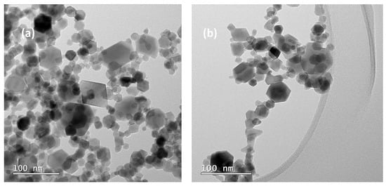
Figure 4.
HRTEM images of (a) NZF@NF (b) and NZF.
The CV curves of the NZF and NZF@NF are displayed in Figure 5a,b in the potential range of −0.5 to 0.4 V in 3M KOH electrolyte at various scan rates, i.e., 5 mV, 10 mV, 15 mV, 20 mV, 30 mV, 50 mV, and 100 mV. The curves of NZF and NZF@NF being nearly rectangular in shape is a testimonial of the reversible system. The absence of a redox peak in the NZF@NF CV curves is due to the pseudo constant rate over the entire voltammetry cycles. The NZF@NF showed a higher CV-integrated area than the NZF electrode due to its higher electrochemical performance and better adhesion between the ferrite and nickel foam. This enhanced electrochemical performance is due to the absence of polymer adhesion and dead area on the surface of active electrode material [19,27]. A larger area and high values of current are observed in NZF@NF compared to NZF, which can be ascribed to the 3D porous structure of the nickel foam that can provide more electro-active sites for the electrochemical reaction [22,23]. Furthermore the CV area can be improved by introduction of highly conductive carbonaceous material, such as graphene oxide and CNTs, which can introduce an EDLC charging mechanism [28,29]. Thus, this hybrid charging strategy can take advantage of the synergy between the EDLC and pseudocapacitor materials. The oxidation peaks are shifted toward the positive side of the axis and reduction peaks are slightly shifted to the negative side of the axis, with an increase in scan rate. The area increases with the increase in the scan rate due to a more activation active area at a higher scan rate.
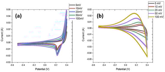
Figure 5.
(a) CV curves of NZF at the potential window of −0.5 to 0.4 V; (b) CV curves of NZF@NF at the potential window of −0.5 to 0.4 V.
To understand the electrochemical properties of the NZF and NZF@NF samples, the galvanostatic charge–discharge was performed at a potential window of −0.5 to 0.4 V at different current densities, ranging from 1 A/g to 10 A/g. Figure 6a,b shows that all curves represent a nonlinear shape due to the faradic behavior of the ferrites materials. The value of specific capacity for NZF was found to be 151.1, 157.8, 130, 105.6, and 77.8 F/g at current densities of 1, 2, 3, 5, and 10 A/g. The values of specific capacitance for NZF@NF were found to be 504.4, 406.7, 350, 277.8, and 200 F/g at the current densities of 1, 2, 3, 5, and 10 A/g, respectively. The comparison of specific capacitance of this work with the earlier reported literature is given in Table 1. The performance of the material synthesized in this work in terms of its specific capacitance is remarkable. The value of specific capacity as a function of current density is plotted in Figure 6c, and the plot of the specific energy against specific power density is plotted in Figure 6d. It is obvious in Figure 6d that the energy density performance of NZF@NF is much better than the NZF. In Figure 6d, at a power density of 450 kW kg−1, an energy density of 17 kWh kg−1 is achieved for the binder-based electrode, while at the same power density, the energy density value reaches 56 kWh kg−1 for the binder-free electrode. This surge in performance for the binder-free electrode can be credited to the increase in electroactive area due to the mesh structure of the nickel foam. The higher capacity of NZF@NF can be attributed to the higher electrical conductivity and porous structure of the nickel foam that facilitate the diffusion of ions and electrons.
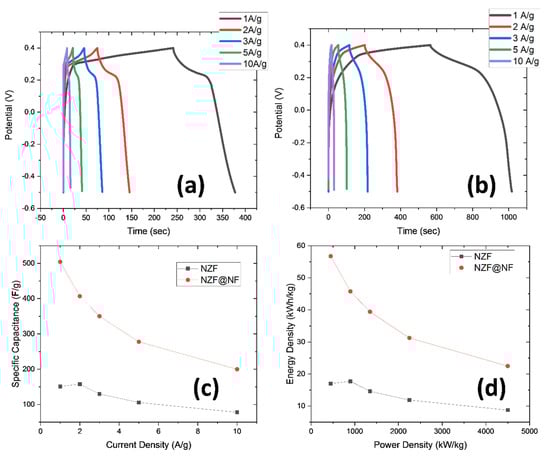
Figure 6.
(a) GCD curves of NZF in the potential window of −0.5 to 0.4 V; (b) GCD curves of NZF in the potential window of −0.5 to 0.4 V; (c) Ragone plot of the specific capacity as a function of the current density; (d) Ragone plot of the energy density and power density.

Table 1.
Comparison of specific capacitance with the earlier reported literature.
The Nyquist plot of the ZF and NZF@NF is shown in Figure 7, using EIS to examine the ion transfer resistance and electrical conductivity of these electrodes. The inset of Figure 7 displayed the EIS at higher frequencies. The solution resistance was calculated from the intercept at the real axis and labeled as Rs and the charge transfer resistance was calculated from the diameter of the semicircle, which is the most characteristics for the supercapacitors and labeled as Rct. The semicircle of the NZF@NF is not seen; this is because of the negligible charge transfer resistance because of the good electrical conductivity of the nickel foam and tight loading of the active material on the nickel foam. The larger diameter of the NZF electrode and higher value of the intercept on the real axis is a demonstration of the larger solution resistance and internal resistance due to the usage of a polymer-based binder. The NZF@NF demonstrated a straighter line than the NZF electrode at the lower-frequency regions, representing small Warburg impedance, thus signifying the rapid transfer of ions across the solution, electrolytes, and on the surface of the electrode for the binder-free electrode. So, the binder-free electrode has outperformed the binder-based electrode owing to its higher electrochemical activity.
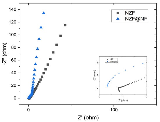
Figure 7.
EIS plot of NZF and NZF@NF while the inset shows the EIS plot at high frequencies.
4. Conclusions
In this work, NZF and NZF@NF electrodes were synthesized via the facile hydrothermal method. The crystalline phase was confirmed via XRD and the morphology was examined by SEM and TEM techniques. The electrochemical properties were investigated by CV, GCD, and EIS methods. The NZF@NF electrode has surpassed the NZF binder-based electrode. The NZF@NF has demonstrated a specific capacitance of 504.4 F g−1 at 1 A g−1 and retained ~70% of the specific capacitance, even at a higher current density of 3 A g−1. It is suggested that the incorporation of highly conductive polymers, CNTs, or reduced graphene oxide can further improve the electrochemical performance. The high electrical conductivity and 3D interconnected porous structure of nickel foam is translated into enhanced electrochemical properties of the NZF@NF electrode.
Author Contributions
B.N. and S.R. are co-first author and contributed equally to the conceptualization, methodology and formal analysis; G.A. and M.O.U. contributed to resources supervision and reviewed the manuscript; F.A. reviewed and edited the first draft; and all authors read, revised and approved the final manuscript. All authors have read and agreed to the published version of the manuscript.
Funding
This research received no external funding. This research was supported and conducted at UET Taxila, Rawalpindi and USPCAS-E, NUST, Islamabad, Pakistan.
Institutional Review Board Statement
Not applicable.
Informed Consent Statement
Not applicable.
Data Availability Statement
The authors confirm that the data supporting the findings of this study are available within the article.
Conflicts of Interest
The authors declare no conflicting interests.
References
- Iro, Z.S.; Subramani, C.; Dash, S. A brief review on electrode materials for supercapacitor. Int. J. Electrochem. Sci. 2016, 11, 10628–10643. [Google Scholar] [CrossRef]
- Jin, T.; Han, Q.; Jiao, L. Binder-free electrodes for advanced sodium-ion batteries. Adv. Mater. 2020, 32, 1806304. [Google Scholar] [CrossRef]
- Vangari, M.; Pryor, T.; Jiang, L. Supercapacitors: Review of materials and fabrication methods. J. Energy Eng. 2013, 139, 72–79. [Google Scholar] [CrossRef]
- Najib, S.; Erdem, E. Current progress achieved in novel materials for supercapacitor electrodes: Mini review. Nanoscale Adv. 2019, 1, 2817–2827. [Google Scholar] [CrossRef]
- Saha, S.; Samanta, P.; Murmu, N.C.; Kuila, T. A review on the heterostructure nanomaterials for supercapacitor application. J. Energy Storage 2018, 17, 181–202. [Google Scholar] [CrossRef]
- Sharma, K.; Arora, A.; Tripathi, S.K. Review of supercapacitors: Materials and devices. J. Energy Storage 2019, 21, 801–825. [Google Scholar]
- Yang, Z.; Tian, J.; Yin, Z.; Cui, C.; Qian, W.; Wei, F. Carbon nanotube-and graphene-based nanomaterials and applications in high-voltage supercapacitor: A review. Carbon 2019, 141, 467–480. [Google Scholar] [CrossRef]
- Manohar, A.; Chintagumpala, K.; Kim, K.H. Mixed Zn–Ni spinel ferrites: Structure, magnetic hyperthermia and photocatalytic properties. Ceram. Int. 2021, 47, 7052–7061. [Google Scholar] [CrossRef]
- Valenzuela, R. Novel applications of ferrites. Phys. Res. Int. 2012, 2012, 1–9. [Google Scholar] [CrossRef]
- Harris, V.; Koon, N.; Williams, C.; Zhang, Q.; Abe, M.; Kirkland, J.; McKeown, D. Direct measurement of octahedral and tetrahedral site environments in NiZn-ferrites. IEEE Trans. Magn. 1995, 31, 3473–3475. [Google Scholar] [CrossRef]
- Mordina, B.; Kumar, R.; Neeraj, N.S.; Srivastava, A.K.; Setua, D.K.; Sharma, A. Binder free high performance hybrid supercapacitor device based on nickel ferrite nanoparticles. J. Energy Storage 2020, 31, 101677. [Google Scholar] [CrossRef]
- Bhujun, B.; Tan, M.T.; Shanmugam, A.S. Study of mixed ternary transition metal ferrites as potential electrodes for supercapacitor applications. Results Phys. 2017, 7, 345–353. [Google Scholar] [CrossRef]
- Cai, Y.-Z.; Cao, W.-Q.; Zhang, Y.-L.; He, P.; Shu, J.-C.; Cao, M.-S. Tailoring rGO-NiFe2O4 hybrids to tune transport of electrons and ions for supercapacitor electrodes. J. Alloy. Compd. 2019, 811, 152011. [Google Scholar] [CrossRef]
- Askari, M.B.; Salarizadeh, P.; Seifi, M.; Di Bartolomeo, A. ZnFe2O4 nanorods on reduced graphene oxide as advanced supercapacitor electrodes. J. Alloy. Compd. 2021, 860, 158497. [Google Scholar] [CrossRef]
- Bashir, B.; Shaheen, W.; Asghar, M.; Warsi, M.F.; Khan, M.A.; Haider, S.; Shakir, I.; Shahid, M. Copper doped manganese ferrites nanoparticles anchored on graphene nano-sheets for high performance energy storage applications. J. Alloy. Compd. 2017, 695, 881–887. [Google Scholar] [CrossRef]
- Hareesh, K.; Shateesh, B.; Joshi, R.P.; Dahiwale, S.; Bhoraskar, V.; Haram, S.; Dhole, S. PEDOT: PSS wrapped NiFe2O4/rGO tertiary nanocomposite for the super-capacitor applications. Electrochim. Acta 2016, 201, 106–116. [Google Scholar] [CrossRef]
- Fan, H.; Quan, L.; Yuan, M.; Zhu, S.; Wang, K.; Zhong, Y.; Chang, L.; Shao, H.; Wang, J.; Zhang, J. Thin Co3O4 nanosheet array on 3D porous graphene/nickel foam as a binder-free electrode for high-performance supercapacitors. Electrochim. Acta 2016, 188, 222–229. [Google Scholar] [CrossRef]
- Kang, J.; Zhang, S.; Zhang, Z. Three-dimensional binder-free nanoarchitectures for advanced pseudocapacitors. Adv. Mater. 2017, 29, 1700515. [Google Scholar] [CrossRef]
- Obodo, R.M.; Shinde, N.M.; Chime, U.K.; Ezugwu, S.; Nwanya, A.C.; Ahmad, I.; Maaza, M.; Ejikeme, P.M.; Ezema, F.I. Recent advances in metal oxide/hydroxide on three-dimensional nickel foam substrate for high performance pseudocapacitive electrodes. Curr. Opin. Electrochem. 2020, 21, 242–249. [Google Scholar] [CrossRef]
- Zhang, L.; Qin, X.; Zhao, S.; Wang, A.; Luo, J.; Wang, Z.L.; Kang, F.; Lin, Z.; Li, B. Advanced Matrixes for Binder-Free Nanostructured Electrodes in Lithium-Ion Batteries. Adv. Mater. 2020, 32, 1908445. [Google Scholar] [CrossRef]
- Zhang, Z.; Zhang, X.; Feng, Y.; Wang, X.; Sun, Q.; Yu, D.; Tong, W.; Zhao, X.; Liu, X. Fabrication of porous ZnCo2O4 nanoribbon arrays on nickel foam for high-performance supercapacitors and lithium-ion batteries. Electrochim. Acta 2018, 260, 823–829. [Google Scholar] [CrossRef]
- Malaie, K.; Ganjali, M.; Alizadeh, T.; Norouzi, P. Hydrothermal growth of magnesium ferrite rose nanoflowers on Nickel foam; application in high-performance asymmetric supercapacitors. J. Mater. Sci. Mater. Electron. 2018, 29, 650–657. [Google Scholar] [CrossRef]
- Chang, Z.; Li, T.; Li, G.; Wang, K. One-pot in-situ synthesis of Ni(OH)2–NiFe2O4 nanosheet arrays on nickel foam as binder-free electrodes for supercapacitors. J. Mater. Sci. Mater. Electron. 2019, 30, 600–608. [Google Scholar] [CrossRef]
- Zhang, G.; Li, W.; Xie, K.; Yu, F.; Huang, H. A One-Step and Binder-Free Method to Fabricate Hierarchical Nickel-Based Supercapacitor Electrodes with Excellent Performance. Adv. Funct. Mater. 2013, 23, 3675–3681. [Google Scholar] [CrossRef]
- Meng, F.; Yang, M.; Zhao, L.; Zhang, Y.; Shang, X.; Jin, P.; Zhang, W. A comparative study of the structural, magnetic and electrochemical properties of Al3+ and Cu2+ substituted NiZn ferrite/reduced graphene oxide nanocomposites. Ceram. Int. 2017, 43, 15959–15964. [Google Scholar] [CrossRef]
- Ivanova, R.; Tsyntsarski, B.; Issa, G.; Spassova, I.; Kovacheva, D.; Velinov, N.; Tsoncheva, T. M0.5Zn0.5Fe2O4 (M=Cu, Co, Mn, Ni) ferrites supported on activated carbon as catalysts for methanol decomposition. Bulg. Chem. Commun. 2021, 53, 93–100. [Google Scholar]
- Edison, T.N.J.I.; Atchudan, R.; Lee, Y.R. Binder-free electro-synthesis of highly ordered nickel oxide nanoparticles and its electrochemical performance. Electrochim. Acta 2018, 283, 1609–1617. [Google Scholar] [CrossRef]
- Zhang, H.; Deng, X.; Huang, H.; Li, G.; Liang, X.; Zhou, W.; Guo, J.; Wei, W.; Tang, S. Hetero-structure arrays of NiCoO2 nanoflakes@ nanowires on 3D graphene/nickel foam for high-performance supercapacitors. Electrochim. Acta 2018, 289, 193–203. [Google Scholar] [CrossRef]
- Raut, S.S.; Sankapal, B.R.; Hossain, M.; Shahriar, A.; Pradhan, S.; Salunkhe, R.R.; Yamauchi, Y. Zinc ferrite anchored multiwalled carbon nanotubes for high-performance supercapacitor applications. Eur. J. Inorg. Chem. 2018, 2018, 137–142. [Google Scholar] [CrossRef]
- Cai, Y.-Z.; Cao, W.-Q.; He, P.; Zhang, Y.-L.; Cao, M.-S. NiFe2O4 nanoparticles on reduced graphene oxide for supercapacitor electrodes with improved capacitance. Mater. Res. Express 2019, 6, 105535. [Google Scholar] [CrossRef]
- Zhu, M.; Zhang, X.; Zhou, Y.; Zhuo, C.; Huang, J.; Li, S. Facile solvothermal synthesis of porous ZnFe₂O₄ microspheres for capacitive pseudocapacitors. RSC Adv. 2015, 5, 39270–39277. [Google Scholar] [CrossRef]
- Sen, P.; De, A. Electrochemical performances of poly (3, 4-ethylenedioxythiophene)–NiFe2O4 nanocomposite as electrode for supercapacitor. Electrochim. Acta 2010, 55, 4677–4684. [Google Scholar] [CrossRef]


Publisher’s Note: MDPI stays neutral with regard to jurisdictional claims in published maps and institutional affiliations. |
© 2021 by the authors. Licensee MDPI, Basel, Switzerland. This article is an open access article distributed under the terms and conditions of the Creative Commons Attribution (CC BY) license (https://creativecommons.org/licenses/by/4.0/).