
Additive Manufacturing and Performance of E-Type Transformer Core

 ,
,  ,
,  ,
,  ,
,  and
and 
Abstract
:
1. Introduction
2. Transformer Core Design
2.1. Commercial Transformer
2.2. 3D Printed Design
3. Methods
3.1. Powder Characteristics
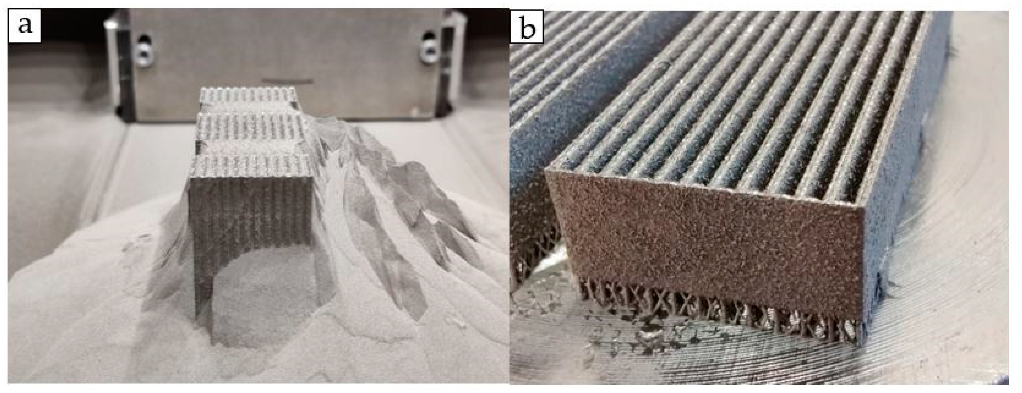
3.2. SLM Printing of the Transformer Core
3.3. Annealing
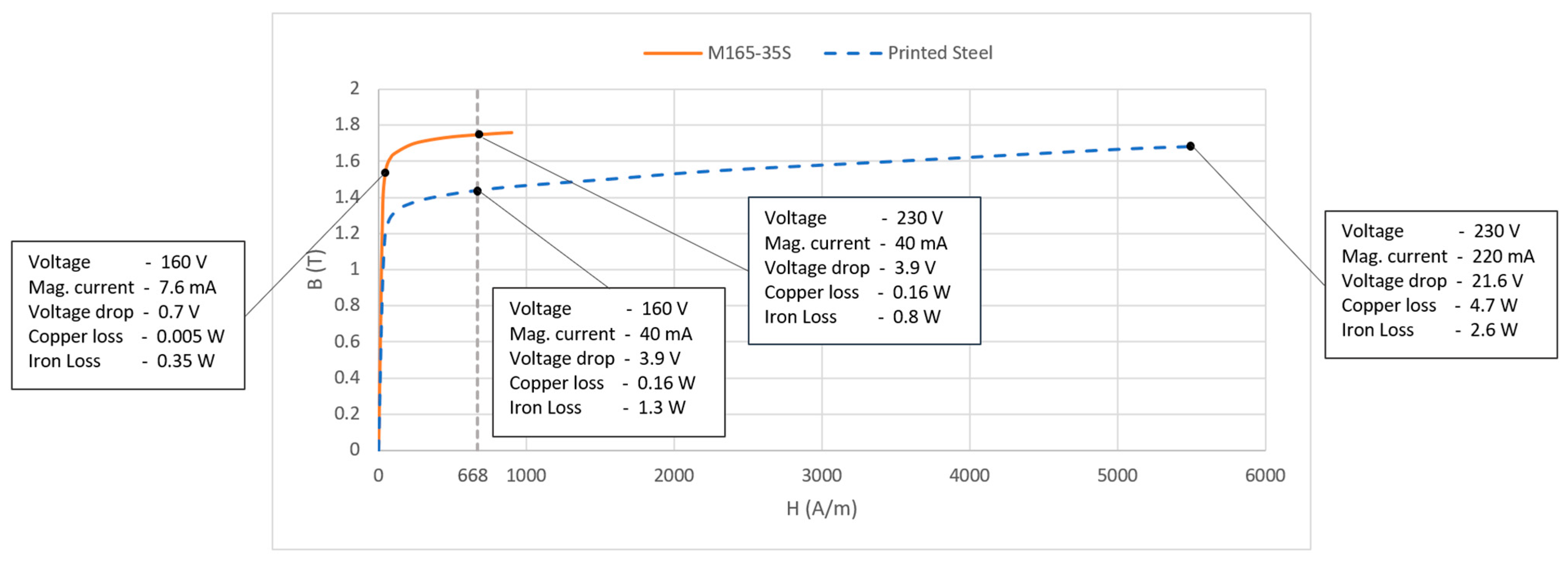
3.4. Material Properties
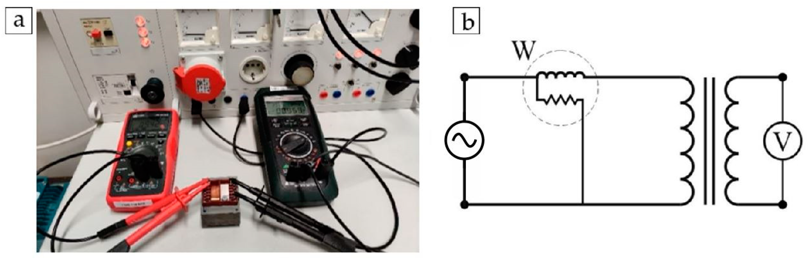
3.5. Transformer Characterization
4. Results
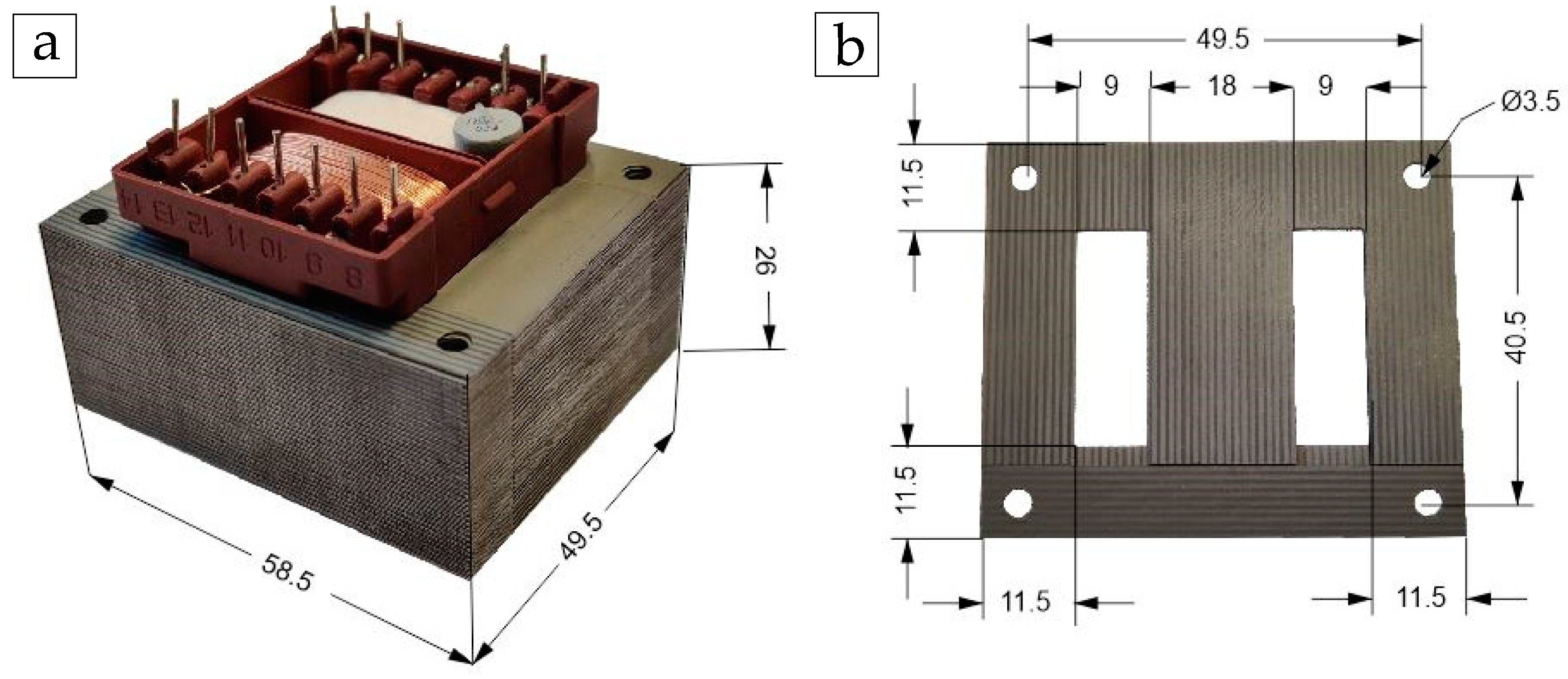
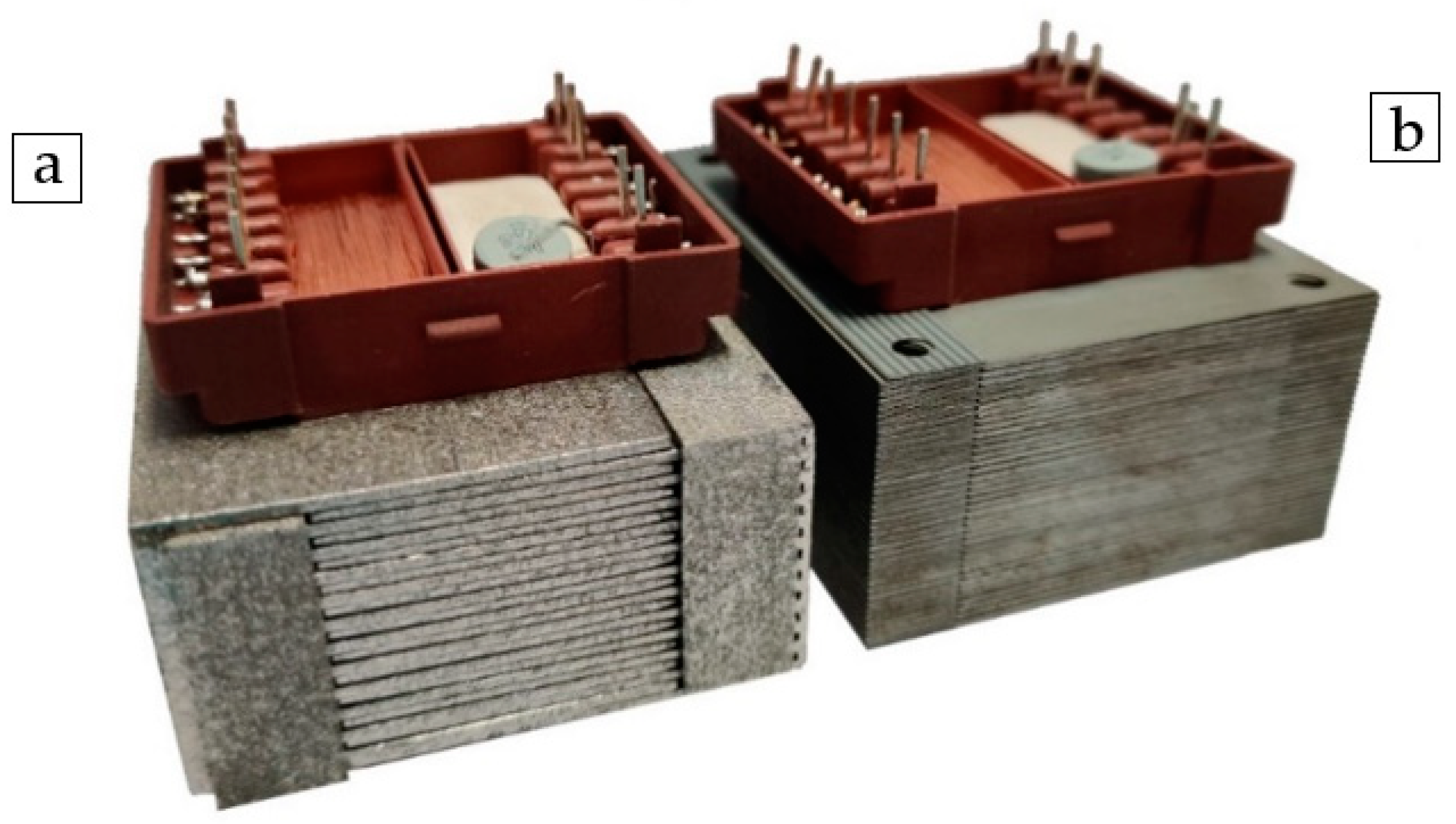
4.1. Assembled Transformer
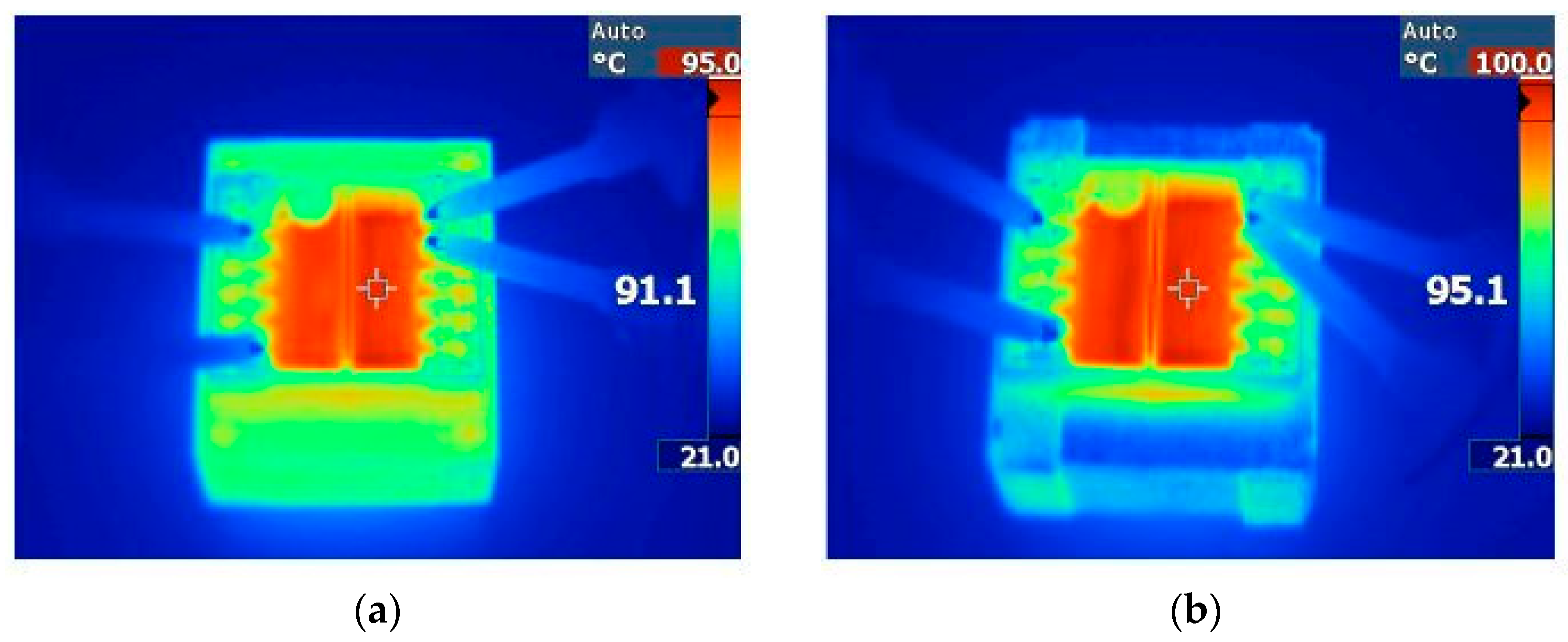
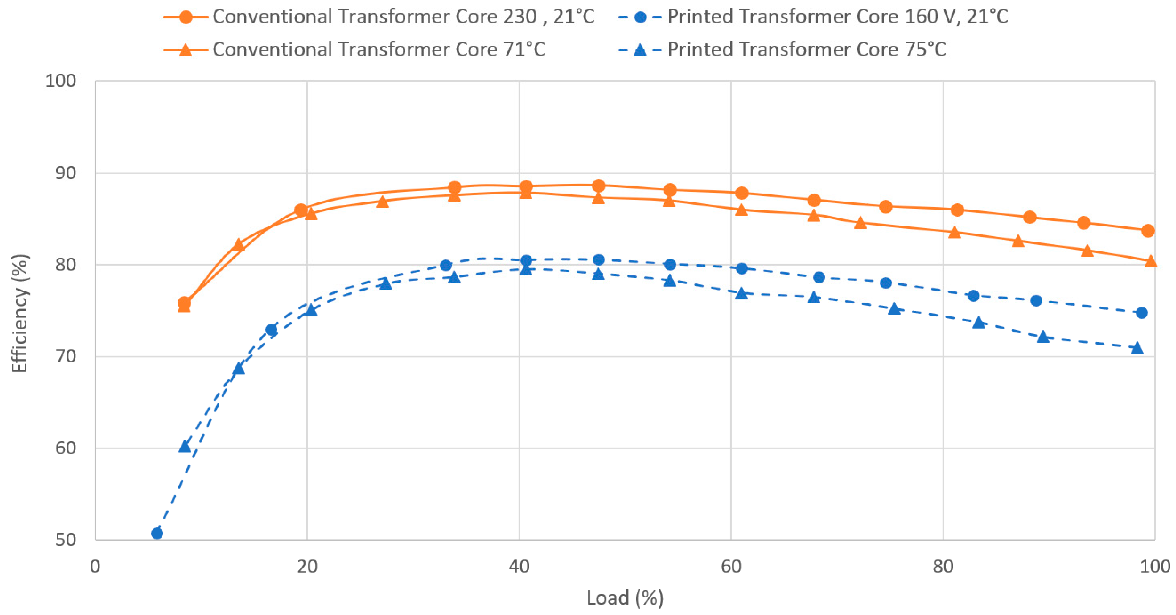
4.2. Performance
5. Discussion
6. Conclusions
Author Contributions
Funding
Institutional Review Board Statement
Informed Consent Statement
Data Availability Statement
Acknowledgments
Conflicts of Interest
References
- How 3D Printing is Redefining Inductor Coil Production|GKN Additive. Available online: https://www.gknpm.com/en/our-businesses/gkn-additive/how-3d-printing-is-redefining-inductor-coil-production/ (accessed on 26 November 2020).
- GE Aviation 3D Prints 30,000th Metal 3D Printed Fuel Nozzle at Auburn, Alabama Plant. Available online: https://3dprint.com/226703/ge-aviation-fuel-nozzle-3d-printed-30000/?fbclid=IwAR38NO-0dAf2BwIkXhVtlC18gAimKnQUSy5KRv-u08InfruK5Zl7Ql1P1HI (accessed on 26 November 2020).
- Conflux Technology is Reinventing Heat Exchangers with 3D Printing » 3D Printing Media Network—The Pulse of the AM Industry. Available online: https://www.3dprintingmedia.network/conflux-technology-reinventing-heat-exchangers/ (accessed on 26 November 2020).
- Ngo, T.D.; Kashani, A.; Imbalzano, G.; Nguyen, K.T.Q.; Hui, D. Additive manufacturing (3D printing): A review of materials, methods, applications and challenges. Compos. Part B Eng. 2018, 143, 172–196. [Google Scholar] [CrossRef]
- Tiismus, H.; Kallaste, A.; Belahcen, A.; Rassolkin, A.; Vaimann, T. Challenges of Additive Manufacturing of Electrical Machines. In Proceedings of the 2019 IEEE 12th International Symposium on Diagnostics for Electrical Machines, Power Electronics and Drives (SDEMPED), Toulouse, France, 27–30 August 2019; pp. 44–48. [Google Scholar] [CrossRef]
- Tiismus, H.; Kallaste, A.; Belahcen, A.; Tarraste, M.; Vaimann, T.; Rassõlkin, A.; Asad, B.; Ghahfarokhi, P.S. AC Magnetic Loss Reduction of SLM Processed Fe-Si for Additive Manufacturing of Electrical Machines. Energies 2021, 14, 1241. [Google Scholar] [CrossRef]
- Stornelli, G.; Faba, A.; Di Schino, A.; Folgarait, P.; Ridolfi, M.R.; Cardelli, E.; Montanari, R. Properties of additively manufactured electric steel powder cores with increased si content. Materials 2021, 14, 1489. [Google Scholar] [CrossRef] [PubMed]
- Yap, C.Y.; Chua, C.K.; Dong, Z.; Liu, Z.H.; Zhang, D.Q.; Loh, L.E.; Sing, S.L. Review of selective laser melting: Materials and applications. Appl. Phys. Rev. 2015, 2, 041101. [Google Scholar] [CrossRef]
- Li, R.; Liu, J.; Shi, Y.; Wang, L.; Jiang, W. Balling behavior of stainless steel and nickel powder during selective laser melting process. Int. J. Adv. Manuf. Technol. 2012, 59, 1025–1035. [Google Scholar] [CrossRef]
- Waasner Magnetic and Technological Properties. Available online: http://www.waasner.de/fileadmin/Assets/PDFs/MaterialCharacteristics_201111.pdf (accessed on 1 March 2021).
- Waasner Material Characterization. Available online: http://www.waasner.de/fileadmin/Assets/PDFs/MaterialCharacteristics_201111.pdf (accessed on 1 March 2021).
- Data Sheet Isovac 235-35 A. Available online: https://www.voestalpine.com/division_stahl/content/download/39689/456867/file/DB_isovac_235-35A_E_281015.pdf (accessed on 1 March 2021).
- Tiismus, H.; Kallaste, A.; Belahcen, A.; Vaimann, T.; Rassõlkin, A.; Lukichev, D. Hysteresis Measurements and Numerical Losses Segregation of Additively Manufactured Silicon Steel for 3D Printing Electrical Machines. Appl. Sci. 2020, 10, 6515. [Google Scholar] [CrossRef]
- Block—PCB Transformers. Available online: http://www.farnell.com/datasheets/1897307.pdf (accessed on 1 March 2021).
- Block—FL 30/12 Safety Isolating Transformer. Available online: https://www.block.eu/en_US/productversion/fl-3012/ (accessed on 1 March 2021).
- Brownsburg Electronic Inc. Transformers and Inductors. Available online: http://www.bei.net/PDF/catalogue2004.pdf (accessed on 1 March 2021).
- Plotkowski, A.; Carver, K.; List, F.; Pries, J.; Li, Z.; Rossy, A.M.; Leonard, D. Design and performance of an additively manufactured high-Si transformer core. Mater. Des. 2020, 194, 108894. [Google Scholar] [CrossRef]
- Suwas, S.; Ray, R.K. Crystallographic Texture of Materials; Springer: London, UK, 2014. [Google Scholar]
- Aconity Additive Manufacturing. Available online: https://aconity3d.com/ (accessed on 29 March 2021).
- Andriushchenko, E.; Kallaste, A.; Belahcen, A.; Vaimann, T.; Rassõlkin, A.; Heidari, H.; Tiismus, H. Optimization of a 3D-Printed Permanent Magnet Coupling Using Genetic Algorithm and Taguchi Method. Electronics 2021, 10, 494. [Google Scholar] [CrossRef]
- Orosz, T.; Rassõlkin, A.; Kallaste, A.; Arsénio, P.; Pánek, D.; Kaska, J.; Karban, P. Robust Design Optimization and Emerging Technologies for Electrical Machines: Challenges and Open Problems. Appl. Sci. 2020, 10, 6653. [Google Scholar] [CrossRef]
- Ghahfarokhi, P.S.; Podgornovs, A.; Kallaste, A.; Cardoso, A.J.M.; Belahcen, A.; Vaimann, T.; Tiismus, H.; Asad, B. Opportunities and Challenges of Utilizing Additive Manufacturing Approaches in Thermal Management of Electrical Machines. IEEE Access 2021, 9, 36368–36381. [Google Scholar] [CrossRef]


| Winding | Turns | Resistance (Ω) | Nominal Voltage (V) | Nominal Current (A) | Insulation Class |
|---|---|---|---|---|---|
| Primary | 1370 | 98 | 230 | 0.17 | H |
| Secondary 1 | 151 | 1.35 | 25.1 | 1.3 | F |
| Secondary 2 | 56 | 2.7 | 9.3 | 0.25 | F |
| Elements | Fe | Si | Mn | Cr | Ni | C |
|---|---|---|---|---|---|---|
| Wt% | Balance | 3.7 | 0.2 | 0.16 | 0.020 | 0.01 |
| Parameter | Value |
|---|---|
| Layer thickness | 50 μm |
| Hatch distance | 120 μm |
| Laser Power | 250 W (primary)/100 W (secondary) |
| Scanning velocity | 0.5 m/s (primary)/0.5 m/s (secondary) |
| Scan strategy | Stripes |
| Environment | Nitrogen |
| Oxygen content | ~0.1% |
| Core | Lamination Thickness (mm) | Fill Factor | Dimensions (mm) | Weight Core (kg) | Weight Coil (kg) | Varnish |
|---|---|---|---|---|---|---|
| Conventional | 0.35 | 0.96 | 58.5 × 49.8 × 26.0 | 0.44 | 0.095 | Yes |
| Printed | 0.95 | 0.89 | 58.8 × 49.9 × 25.0 | 0.41 | 0.095 | No |
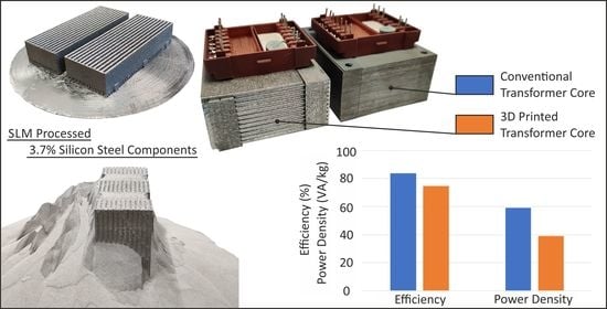
| Parameter (Full Load, 21 °C) | 3D Printed Core | Conventional Core |
|---|---|---|
| Nominal Voltage | 160 V | 230 V |
| Nominal Current | 0.17 A | 0.17 A |
| Power Factor | 0.97 | 0.97 |
| Input Power | 27.2 VA | 39.1 VA |
| Output power | 19.8 VA | 31.8 VA |
| Efficiency (ambient temperature) | 74.7% | 83.8% |
| Efficiency (operating temperature) | 70.1% | 80.5% |
| Power Density (Core) | 47 VA/kg | 72 VA/kg |
| Power Density (Full Transformer) | 39 VA/kg | 59 VA/kg |
Publisher’s Note: MDPI stays neutral with regard to jurisdictional claims in published maps and institutional affiliations. |
© 2021 by the authors. Licensee MDPI, Basel, Switzerland. This article is an open access article distributed under the terms and conditions of the Creative Commons Attribution (CC BY) license (https://creativecommons.org/licenses/by/4.0/).
Share and Cite
Tiismus, H.; Kallaste, A.; Belahcen, A.; Rassolkin, A.; Vaimann, T.; Shams Ghahfarokhi, P. Additive Manufacturing and Performance of E-Type Transformer Core. Energies 2021, 14, 3278. https://doi.org/10.3390/en14113278
Tiismus H, Kallaste A, Belahcen A, Rassolkin A, Vaimann T, Shams Ghahfarokhi P. Additive Manufacturing and Performance of E-Type Transformer Core. Energies. 2021; 14(11):3278. https://doi.org/10.3390/en14113278
Chicago/Turabian StyleTiismus, Hans, Ants Kallaste, Anouar Belahcen, Anton Rassolkin, Toomas Vaimann, and Payam Shams Ghahfarokhi. 2021. "Additive Manufacturing and Performance of E-Type Transformer Core" Energies 14, no. 11: 3278. https://doi.org/10.3390/en14113278
APA StyleTiismus, H., Kallaste, A., Belahcen, A., Rassolkin, A., Vaimann, T., & Shams Ghahfarokhi, P. (2021). Additive Manufacturing and Performance of E-Type Transformer Core. Energies, 14(11), 3278. https://doi.org/10.3390/en14113278