Article

Analysis of Effect of the Magnetization Distribution of Multi-Pole PM on SPMSM Performance Using Equivalent Magnetic Circuit Considering Dead Zone

1
Department of Automotive Engineering, Hanyang University, Seoul 04763, Korea
2
Steel Solution R&D Center, Posco, Incheon 21985, Korea
3
Interactive Robotics R&D Division, Korea Institute of Robotics & Technology Convergence, Pohang 37553, Korea
*
Author to whom correspondence should be addressed.
Energies 2021, 14(11), 3279; https://doi.org/10.3390/en14113279
Submission received: 19 April 2021 / Revised: 26 May 2021 / Accepted: 2 June 2021 / Published: 3 June 2021
(This article belongs to the Special Issue Analysis, Design and Optimization of Electric Machines)

Abstract

:
In multi-pole permanent magnets (PMs) such a ring-type PMs, as multi-poles are magnetized in one segment, the ends of each pole are weakly magnetized, which is known as the dead zone. Thus, when analyzing characteristics of the motor with multi-pole PMs, accurate results can be obtained by considering the magnetization distribution. For this reason, this paper proposed an equivalent magnetic circuit (EMC) for external-rotor surface-mounted permanent magnet synchronous motors (SPMSMs) considering the dead zone to analyze the effects of the dead zone on the characteristics of the motor. As the magnetization in the dead zone gradually decreases toward the end of the pole, the magnetization distribution is assumed to have a trapezoidal shape. To describe the magnetization distribution, each pole was divided into several elements, and the equivalent residual magnetic flux density was applied to the elements of the dead zone. Finally, the validity of the proposed EMC was verified by comparing the back electro-motive force and air-gap magnetic flux density obtained by the EMC, finite-element analysis, and test.

1. Introduction

Permanent magnet synchronous motors (PMSMs) are widely used for industrial and household applications due to their high power density, torque density, and efficiency [1,2,3,4,5]. Among them, as surface-mounted PMSMs (SPMSMs) generally have a smaller cogging torque, torque ripple, and vibration than interior permanent magnet synchronous motors (IPMSMs) do, they are widely used for robot applications that require precise control or as a motor for home appliances requiring low noise and vibration characteristics [6,7]. SPMSMs also have the advantages of high manufacturing capabilities and simplicity. However, when an external-rotor SPMSM is operated by direct-drive, the number of poles is often increased for low-speed, high-torque characteristics. In this case, as the number of PM segments is large and the size of the PM segment is small, the manufacturing capabilities are decreased. In order to maximize the advantages of the SPMSM manufacturing capabilities, SPMSMs with a large number of poles are often produced as multi-pole PMs, with multiple poles in one segment, as shown in Figure 1a. As multiple poles are magnetized in one segment, the ends of each pole are weakly magnetized in the magnetization process. The magnetization distribution of this weakly magnetized region, known as the dead zone, is described in Figure 1b [8]. The dead zone angle is determined by various factors such as shape of the magnetizing fixture and arrangement of the magnetizing coil [9]. This dead zone changes the magnetization distribution of the PM according to its shape and dead zone angle, which directly affects the performance of the motor, such as the back electro-motive force (BEMF) and cogging torque [10]. This occurs because the fundamental and harmonic components of the magnetic flux caused by the PM vary depending on the dead zone angle. Therefore, it is essential to analyze and design the motor in consideration of the magnetization distribution of the PM [11].
Finite element analysis (FEA) and equivalent magnetic circuit (EMC) are commonly used in design and analysis of the electric motors. With the increased computing power and the development of commercial FEA programs, motor design and analysis using FEA are widely utilized. However, due to the advantages of short computing time and simple structure, EMCs are still widely studied. Although accurate results can be obtained by using finite element analysis, it requires pre-processing and a long analysis time. In this point of view, the equivalent magnetic circuit can be an alternative because of its fast computation time with agreeable accuracy [12,13,14,15]. In recent years, many studies have been conducted to improve the accuracy of the EMC while maintaining the advantages of the short computation time of the EMC. Manju Bhashini et al. proposed an EMC for a fractional-slot PMSM considering saturation, the fringing effect in the airgap, and the relative motion of the rotor [16]. Haschen and Ponick proposed an improved EMC to calculate the slot leakage flux utilizing the frozen permeability method [17]. In this paper, the EMC for the external-rotor SPMSMs was built to investigate the effects of the dead zone on the characteristics of the motor. To describe the dead zone of the PM using an EMC, the PM was divided into several elements, and the magneto-motive force (MMF) of the PM was expressed according to the circumferential position of the PM. Then, the no-load and load characteristics of the SPMSM according to the dead zone angle were calculated and analyzed using the proposed EMC, and the results were compared with FEA. Finally, the proposed EMC was verified by comparing the results of the EMC, FEA, and test.

2. Equivalent Magnetic Circuit Considering Dead Zone of Multi-Pole PMs

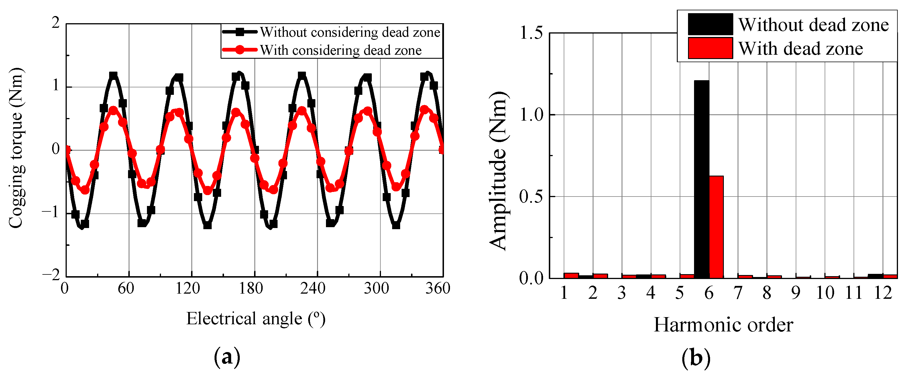
2.1. Motor Performance Analysis with/without Considering Dead Zone

To investigate the performance difference depending on whether the dead zone is considered or not, 2-D electromagnetic FEA was conducted. The reference motor was a 3-phase, 48-pole, 36-slot external-rotor SPMSM using a ferrite PM, and the configuration of the model is shown in Figure 1a with the multi-pole PM. The PM of the reference motor used in this study had four poles magnetized in one segment, and therefore, as it was a 48-pole motor, a total of 12 PM segments were attached. Figure 2 shows the cogging torque waveform and harmonic analysis results with/without considering the dead zone, when the dead zone angle was 28.8°. The cogging torque peak-to-peak values with/without considering the dead zone was 1.29 and 2.46 Nm, respectively, which is a large difference. This difference in cogging torque occurred because the no-load air-gap magnetic flux changes according to the dead zone angle. It can also be seen from Figure 2b that the time harmonic order in which the cogging torque was largely generated did not change, as the pole/slot combination did not change. Therefore, it is necessary to analyze and design the motor in consideration of the dead zone. Thus, an EMC considering the dead zone of the multi-pole PM is proposed in the next section.

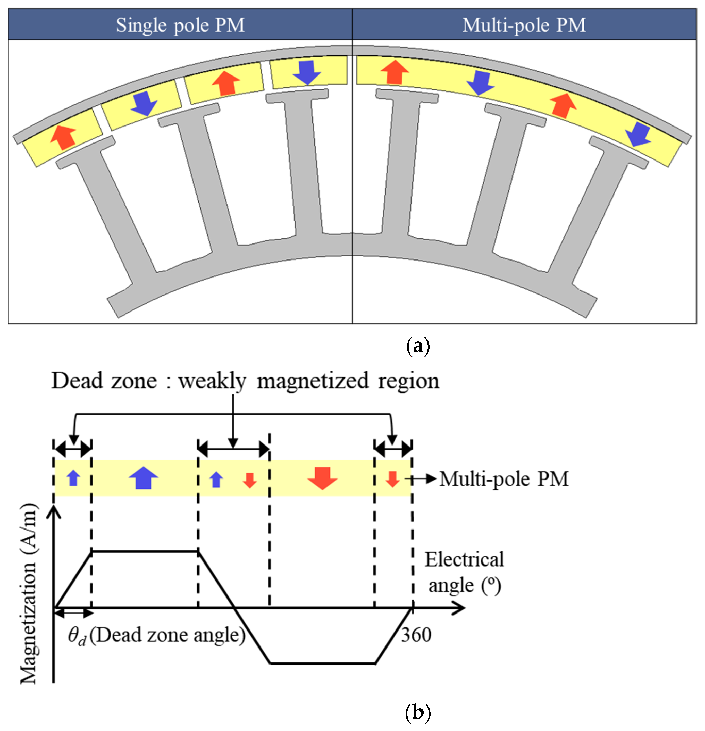
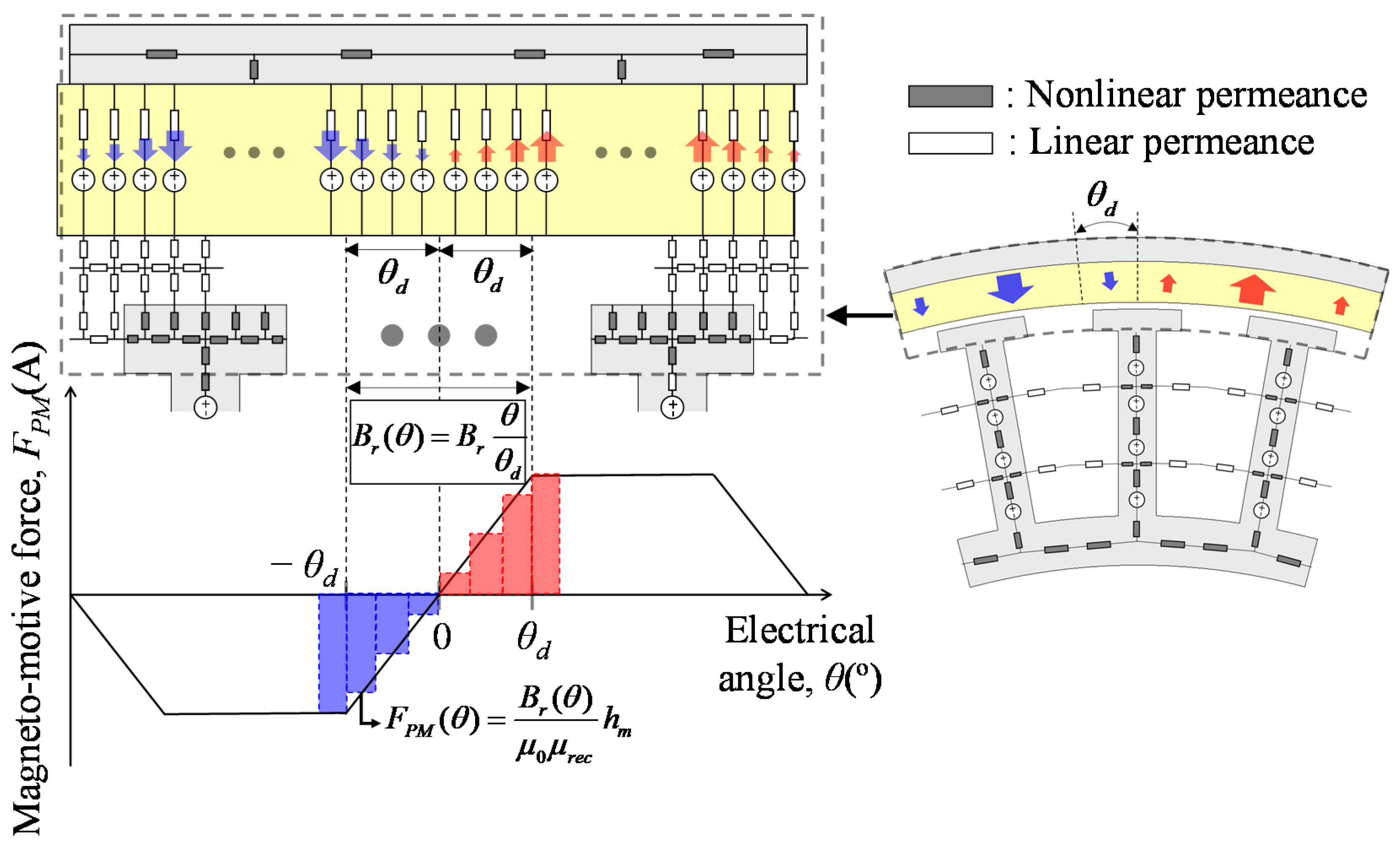
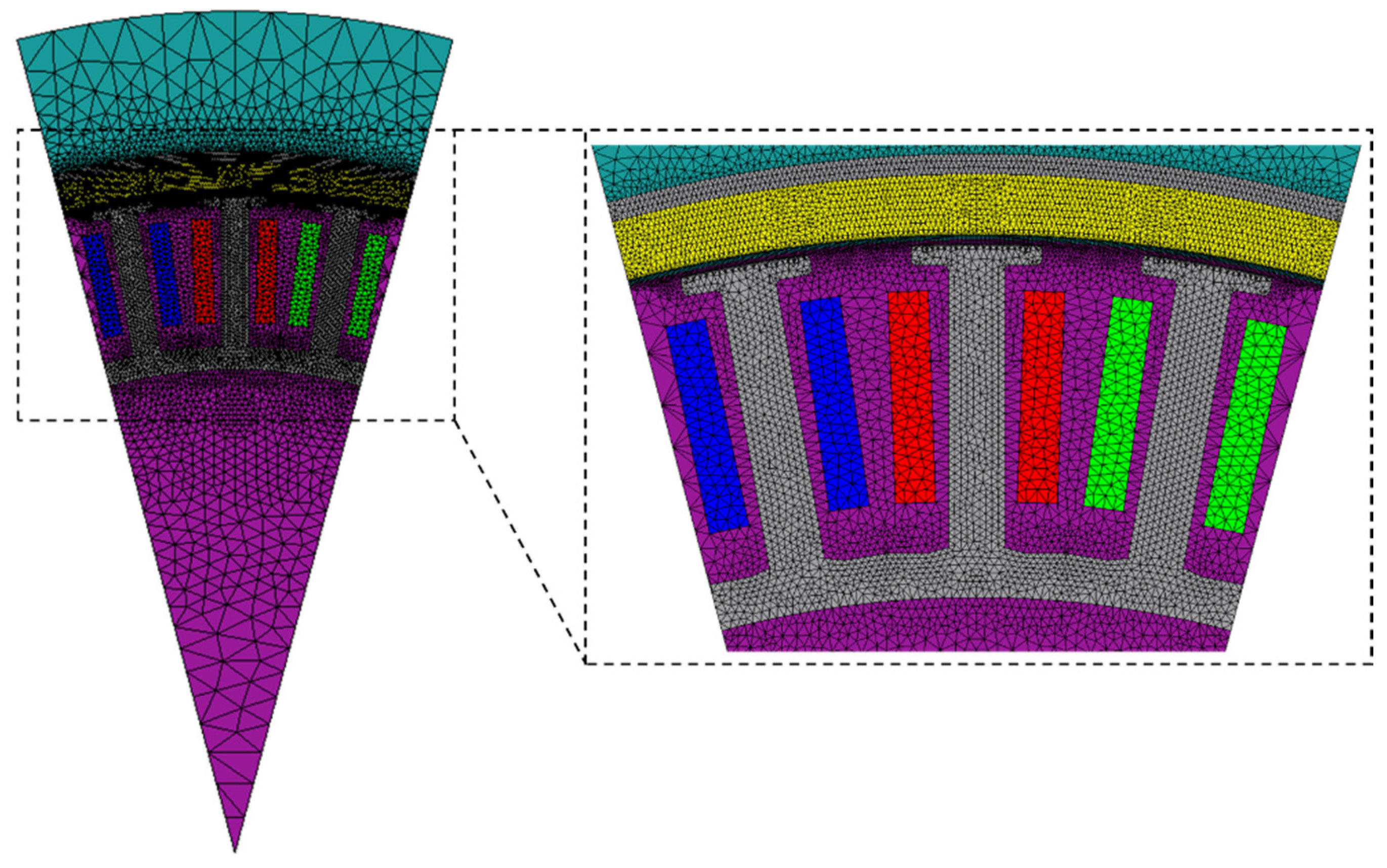
2.2. Permanent Magnet Modeling Considering Dead Zone Angle

Figure 3 shows the overall circuit of the proposed EMC and the PM circuit considering the dead zone. As shown in Figure 3, the elements of the proposed EMC consisted of the rotor core, PM, air gap, stator slot opening, stator core, and stator slot leakage. The magnetization distribution in the dead zone can be determined by the magnetization fixture or applied external magnetic field [18]. However, regardless of the shape of the magnetization distribution, the magnetization at the center between two adjacent poles is always zero. In addition, in the dead zone, the magnetization gradually decreases toward the end of the pole. Therefore, it can be assumed that the magnetization distribution has a trapezoidal shape, as shown in Figure 3. As the PM has a trapezoidal magnetization distribution, the magnetization of the PM varies linearly in the dead zone according to the circumferential position. As shown in Figure 3, PMs were divided into elements to describe the PM magnetization in the dead zone. Then, as the residual magnetic flux density of the PM is proportional to the magnetization, the residual magnetic flux density in the dead zone was modeled in a linear form with respect to the circumferential position as follows:
B r ( θ ) = B r θ θ d
and the MMF of the PM is expressed as follows:
F P M ( θ ) = B r ( θ ) μ 0 μ r e c h m
where FPM is the magneto-motive force of the PM, Br is the residual magnetic flux density, hm is the PM thickness, θ is the circumferential position of each element of the PM in electrical degrees, θd is the dead zone angle, and μ0 and μrec are the vacuum permeability and recoil permeability, respectively.

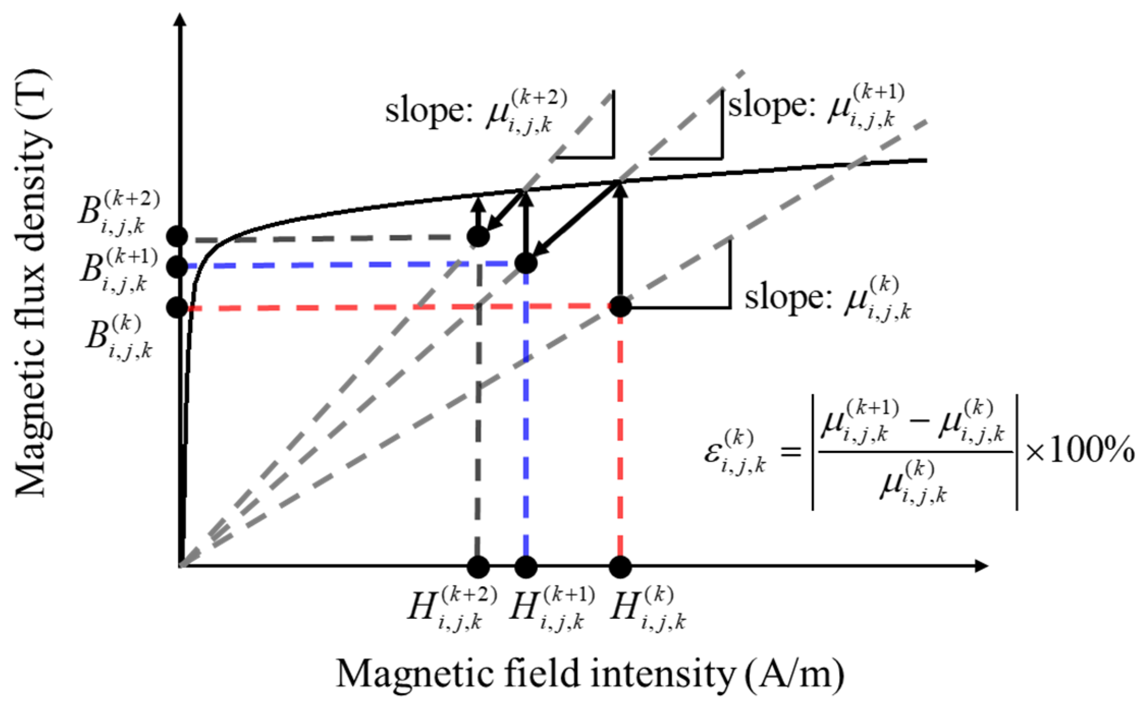
2.3. Numerical Solution of EMC

The EMC can be solved in the same way as the electric circuit. By applying Kirchhoff’s voltage law, the permeance matrix [P], the flux source column vector [Φ], and the magnetic potential column vector [F] can be obtained, and their relations are as follows [19]:
[ F ] = [ P ] 1 [ Φ ]
Then, with the calculated magnetic potential, the magnetic flux Φ and magnetic flux density B are calculated as follows:
Φ i j = ( F ( i ) F ( j ) ) P ( i , j )
B = Φ A
where A is the cross-sectional area, and i and j are the nodes numbers.
The nonlinear permeance was calculated in the following process [20], which is described in Figure 4.
  • For an arbitrary node or element (i, j, k) for the kth iteration process, magnetic flux density B i , j , k ( k ) is calculated based on the existing permeability μ i , j , k ( k ) .
  • Then, permeability μ i , j , k ( k ) is renewed as μ i , j , k ( k + 1 ) using magnetic field intensity H i , j , k ( k ) , where H i , j , k ( k ) is calculated by dividing B i , j , k ( k ) into μ i , j , k ( k ) .
  • If ε ( k ) > tolerance, the aforementioned procedure is performed again, and k is also renewed as k + 1, where ε ( k ) = | ( μ ( k + 1 ) μ ( k ) ) / μ ( k ) | × 100 % .
  • If ε ( k ) tolerance, save the calculated parameters.
The flux linkage, BEMF, and torque calculation method using the proposed EMC are referred to [20].

3. Analytical Results and Comparison with FEA

For a 48-pole and 36-slot external-rotor SPMSM, as shown in Figure 1a, with a multi-pole PM, the performance according to the dead zone angle was analyzed using the EMC. In addition, the obtained results using the proposed EMC and FEA were compared to validate the EMC. The specifications of the target motor are summarized in Table 1. The configuration of the FEA model is shown in Figure 5. The number of elements was 16,496 and the number of nodes was 9780, the analysis was conducted by dividing one electrical cycle into 180 steps, and the computing time was 4 min per model.
In addition, the total number of elements of the proposed EMC was 2207, the elements in the circumferential direction of the air gap were divided into 720 to investigate the effect of the dead zone angle in detail, and the computing time per model was about 30 s.

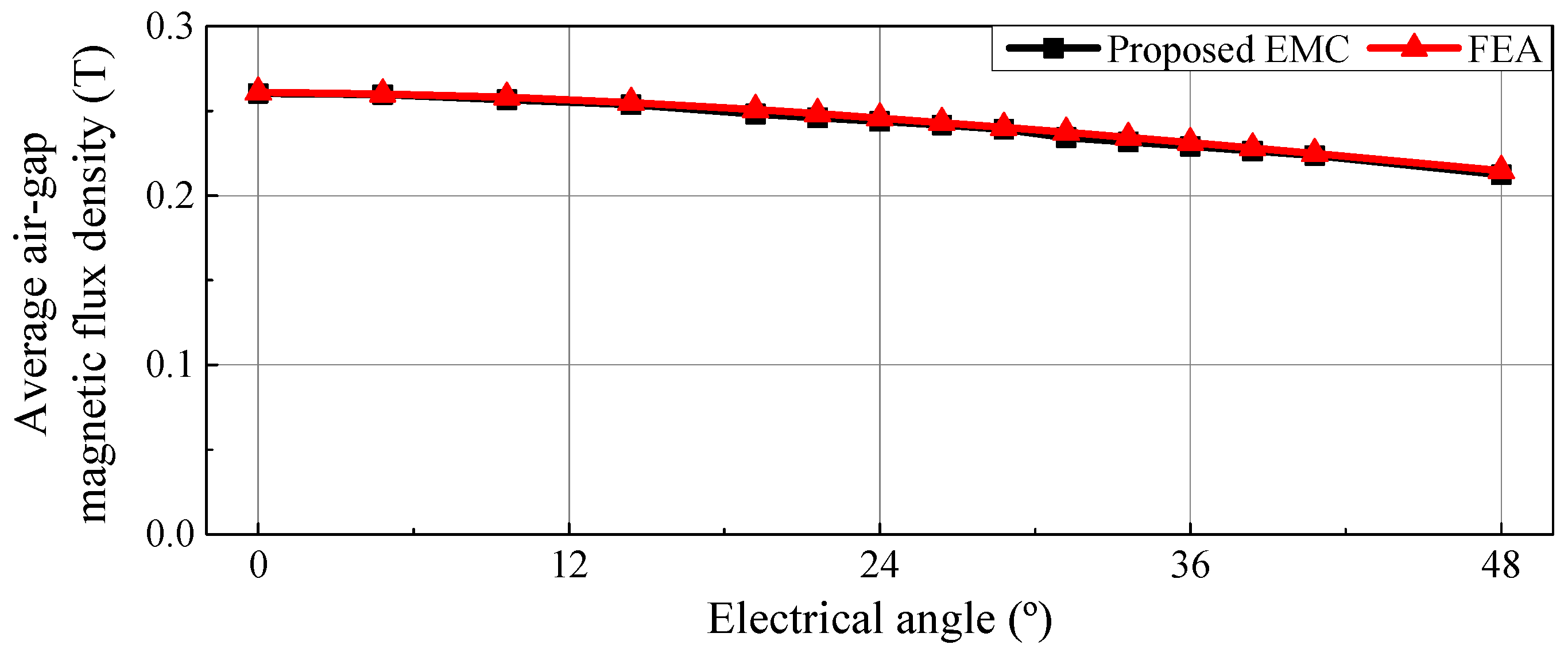
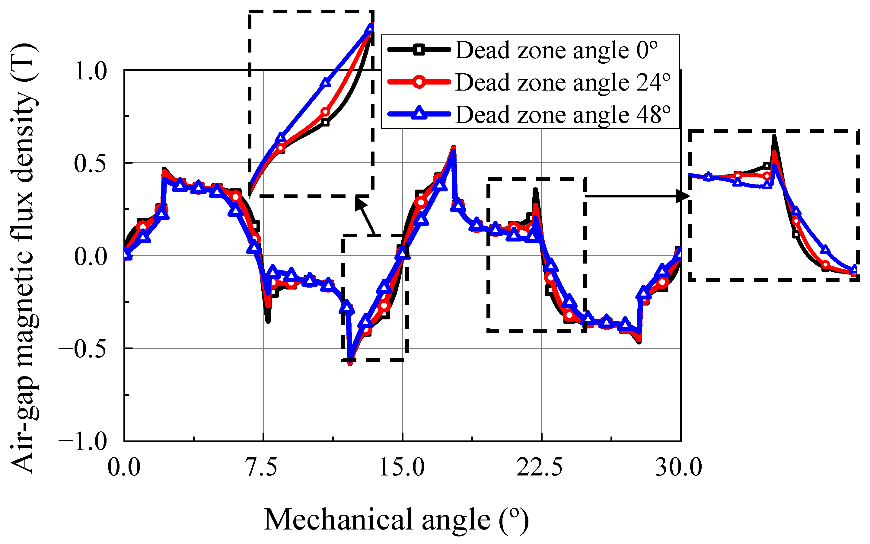
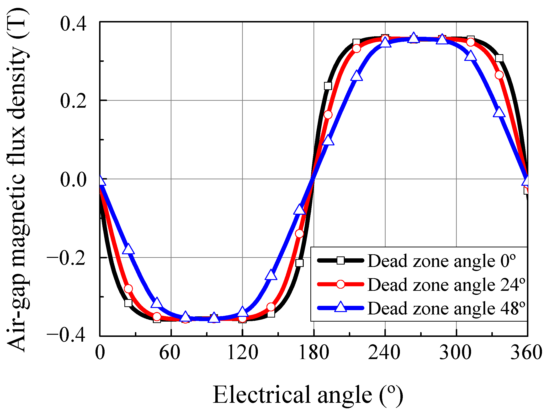
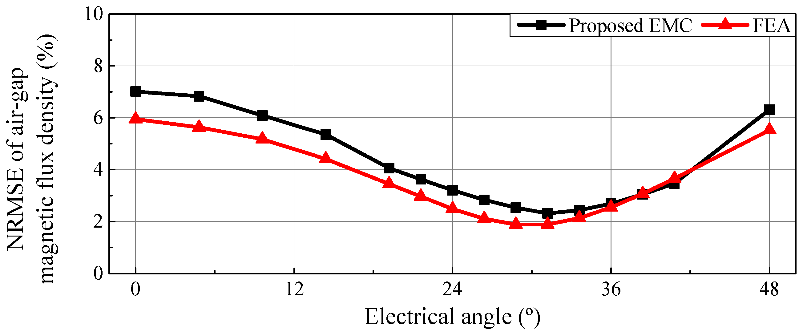
3.1. No-Load Air-Gap Magnetic Flux Density Distribution
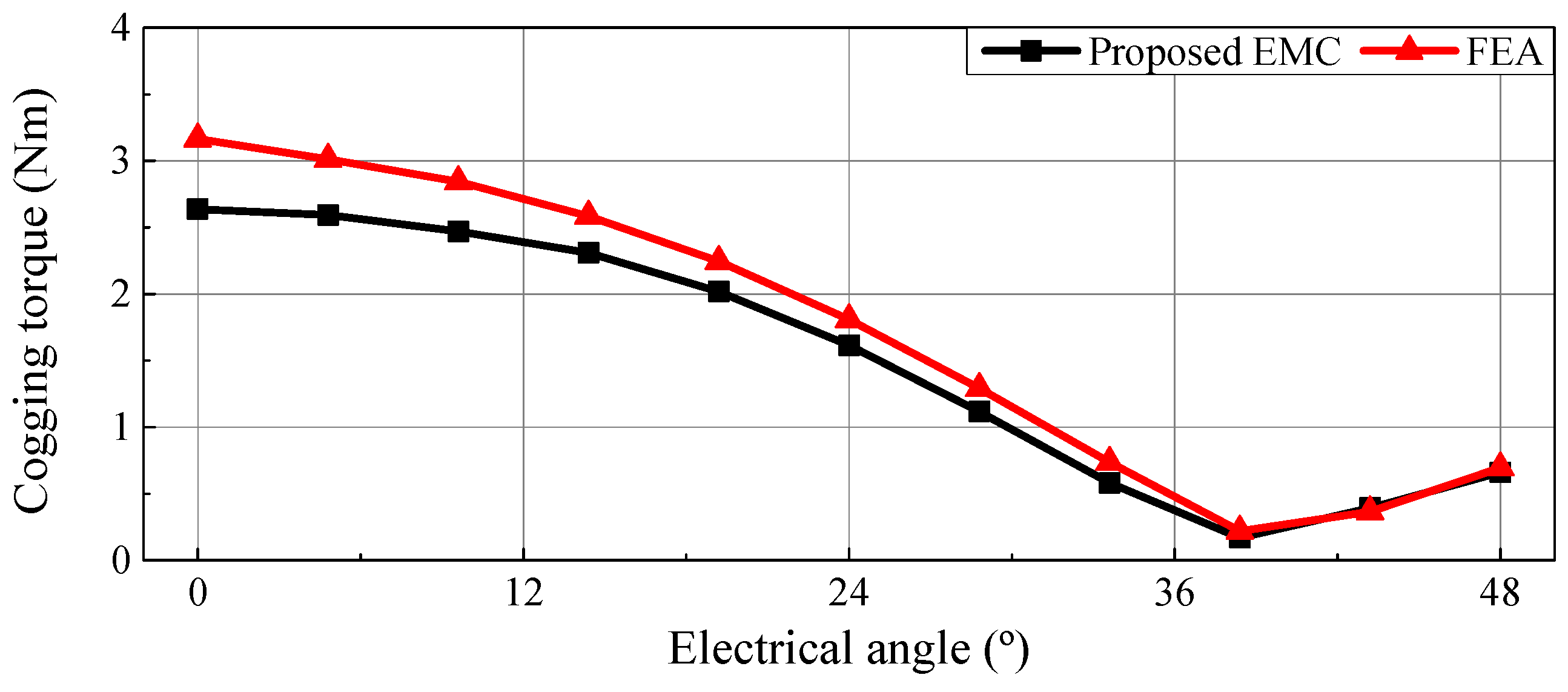
The air-gap flux density under the no-load condition was calculated using the proposed EMC. Figure 6 shows the no-load radial air-gap magnetic flux density distribution at dead zone angles of 0°, 24°, and 48°. As the dead zone increased, both ends of the pole became weakly magnetized. Therefore, the difference in the air-gap magnetic flux density was particularly significant at the mechanical angles of 0°, 7.5°, 15°, 22.5°, and 30°, which are the ends of the poles.
In addition, the air-gap magnetic flux density at the center of the stator tooth in the air gap was calculated according to the dead zone angle, as shown in Figure 7.
The difference in the air-gap magnetic flux density distribution and waveform will lead to a difference in motor performance such as cogging torque, torque ripple, and BEMF harmonics.
In addition, the average air-gap magnetic flux density varied according to the dead zone angle. The average air-gap magnetic flux density calculated using the proposed EMC and FEA is shown in Figure 8. It was figured out that the average air-gap magnetic flux density decreased with the dead zone angle, as the total MMF of the PM decreased. As the average air-gap magnetic flux density decreased with the dead zone angle, the armature current for the same average torque was predicted to increase. Therefore, it is essential to analyze the motor considering the dead zone angle for accurate motor performance prediction. It was also confirmed that the results of the proposed EMC and FEA were well matched.

3.2. Cogging Torque

The cogging torque according to the dead zone angle was calculated using the proposed EMC, and its results were compared with the FEA results in Figure 9. The cogging torque decreased and then increased from a certain dead zone angle, which was 38.4° in the reference motor. As the air-gap magnetic flux density distribution was greatly affected by the dead zone angle, cogging torque was also affected by the dead zone angle. The increase in the dead zone angle was similar to the decrease in the pole angle of the motor, so the cogging torque decreased and then increased with the dead zone angle. Furthermore, it was confirmed that this trend was the same in the proposed EMC and FEA. Therefore, using the proposed EMC, the dead zone angle at which the cogging torque was minimum can be calculated and reflected in the design stage.

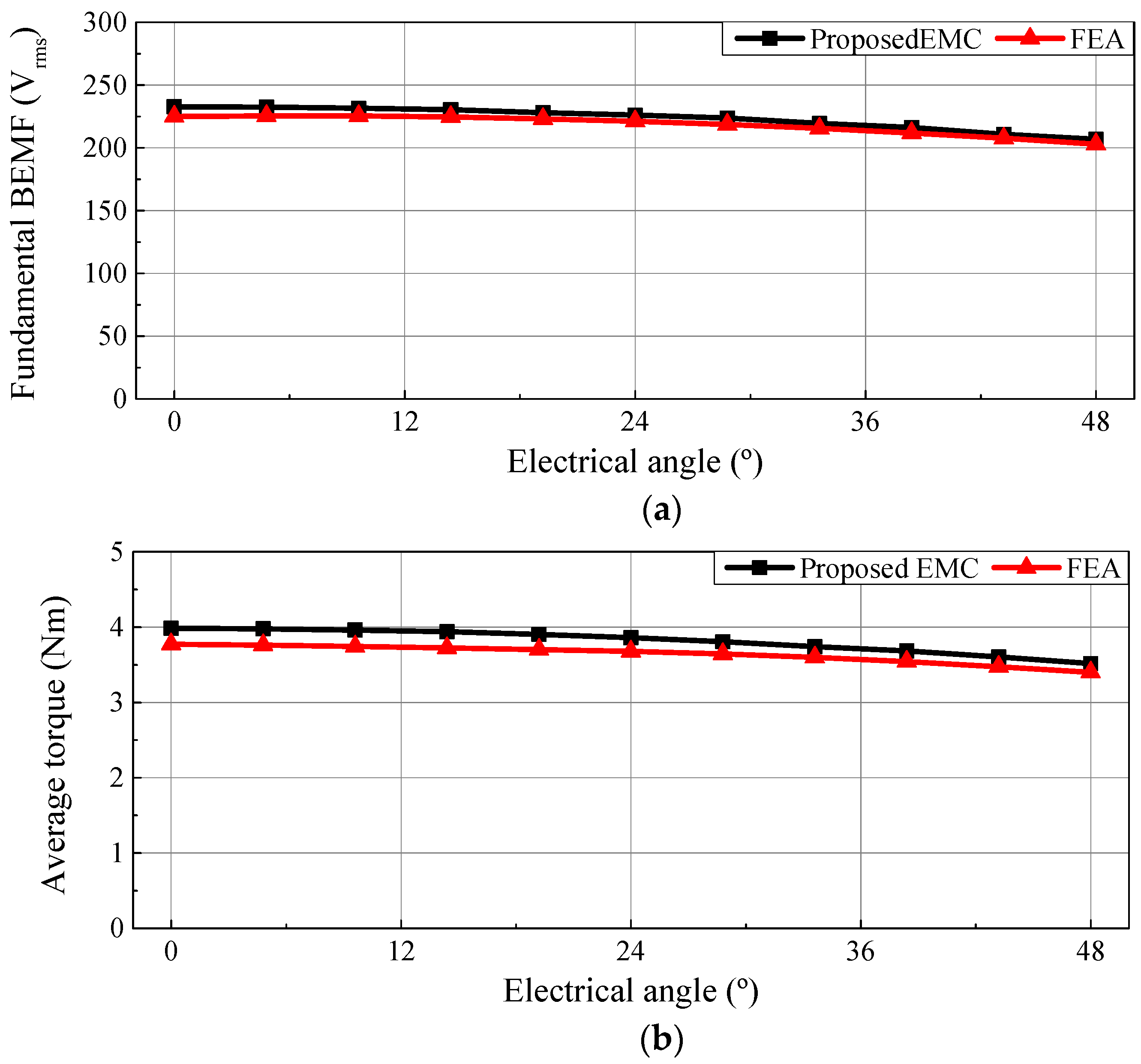
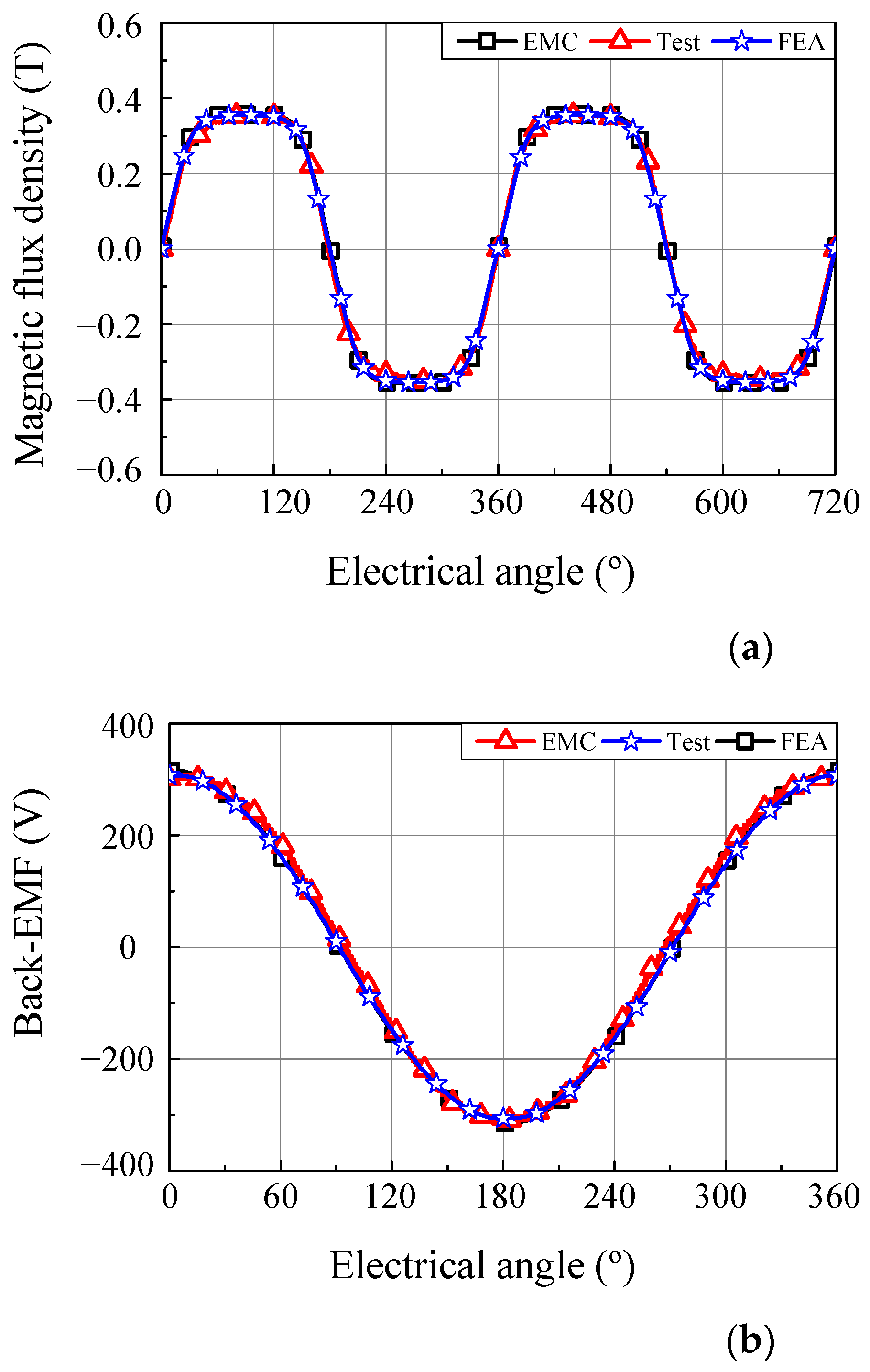
3.3. Back Electro-Motive Force and Average Torque
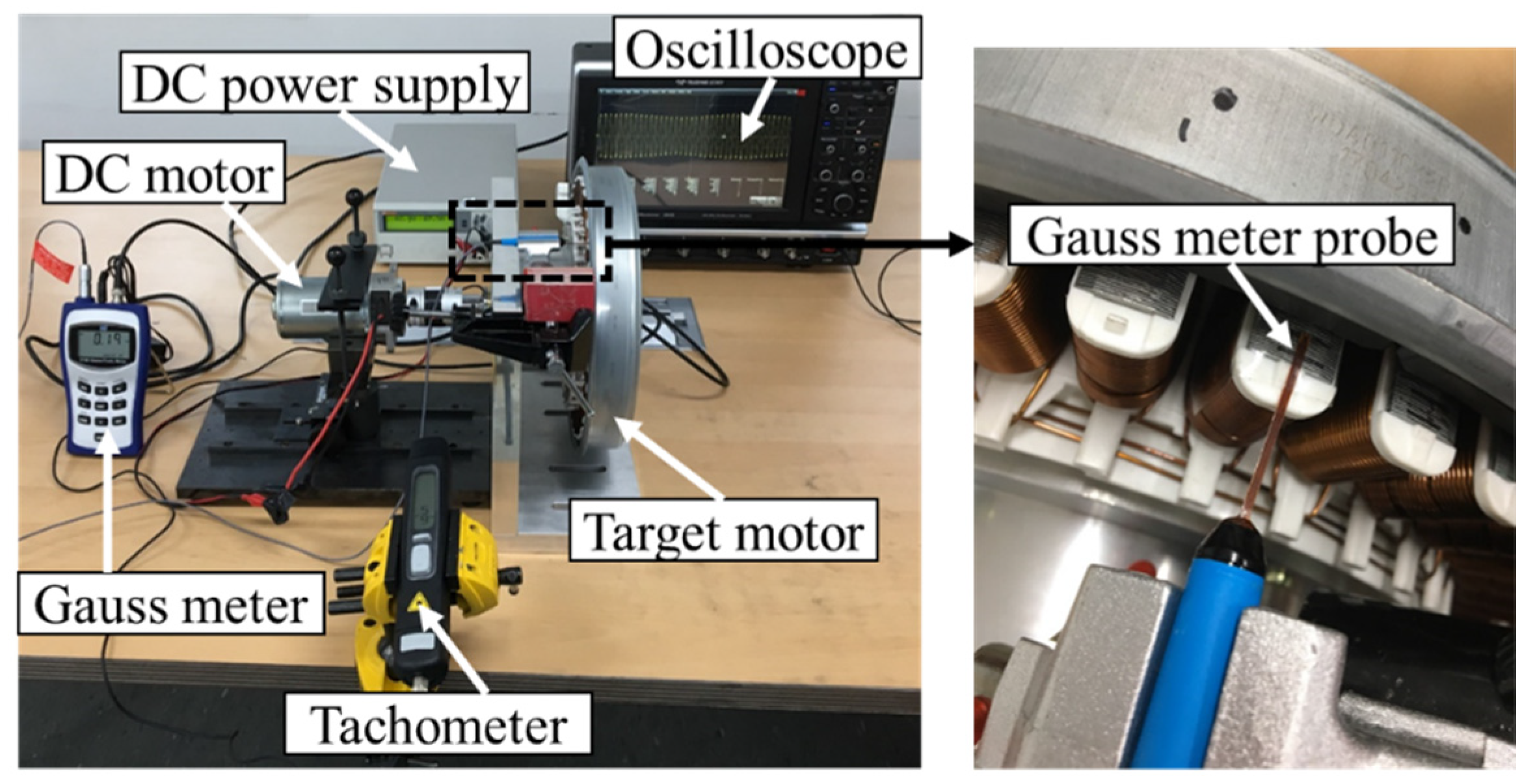
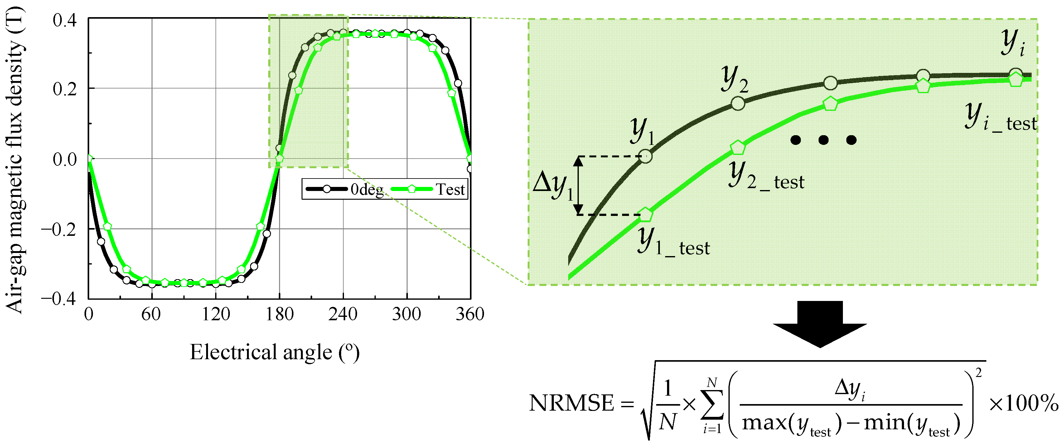
The amplitude of fundamental BEMF and average torque according to the dead zone angle was calculated using the proposed EMC and FEA, as shown in Figure 10. The BEMF was calculated at the rotational speed of 1000 rpm, and the average torque was calculated under the rated current condition. The amplitude of the fundamental BEMF and average torque decreased with the dead zone angle, because the increased region of the weakly magnetized PM led to a decrease in the total MMF of the PM. Therefore, the armature current to satisfy the same average torque increased with the dead zone angle. However, as can be seen from the waveform of the no-load air-gap magnetic flux density in Figure 7, the air-gap magnetic flux density waveform became sinusoidal with the dead zone angle. Accordingly, it was predicted that the harmonic component of the BEMF and torque ripple will decrease with the dead zone angle. Moreover, it was confirmed that the results of the proposed EMC and FEA were well matched.

4. Verification

In order to verify the proposed EMC, verification was performed through the no-load test of the reference motor. First, as it was difficult to measure the exact dead zone angle of the reference motor, the dead zone angle of the reference motor was estimated by an indirect method. As the waveforms of the air-gap magnetic flux density of the motor and the dead zone angle had a very direct relationship, which is shown in Figure 6 and Figure 7 in Section 3, the air-gap magnetic flux density was measured to estimate the dead zone angle of the reference motor, as shown in Figure 11. A gauss meter probe was attached to measure the air-gap magnetic flux density at the position corresponding to the center of the stator’s tooth in the air gap, and the air-gap magnetic flux density was measured while rotating the rotor electrically 360°. Then, the normalized root-mean-square error (NRMSE) of the air-gap magnetic flux density waveform obtained using the proposed EMC was calculated according to the dead zone angle. Here, NRMSE is expressed as follows:
NRMSE = 1 N × i = 1 N ( y i , test y i max ( y test ) min ( y test ) ) 2 × 100 %
where y is the response’s value, which is the air-gap magnetic flux density, and N is the number of data points. The calculation process of the NRMSE of the air-gap magnetic flux density is shown in Figure 12, and the NRMSE according to the dead zone angle is shown in Figure 13. Among them, the dead zone angle with the minimum NRMSE was estimated as the dead zone angle of the reference model.
Here, the NRMSEs obtained using the FEA were also compared. The NRMSEs of the proposed EMC and FEA had minimum values of 2.32% and 1.89%, respectively, where the dead zone angles were 31.2° and 28.8°, respectively. It was confirmed that the dead zone angle with minimum NRMSE was similar in FEA and the proposed EMC. The air-gap magnetic flux density waveform and the BEMF waveform at 1000 rpm were compared to the test result, as shown in Figure 14. The results of the EMC were calculated at 31.2°, and the FEA results were calculated at 28.8°. As can be seen in Figure 14, the results of the test, FEA, and the proposed EMC were well matched. The fundamental BEMFs of the proposed EMC, FEA, and test were 219.6 Vrms, 218.6 Vrms, and 221.9 Vrms, respectively. The errors of the BEMF of the proposed EMC and FEA were 1.04% and 1.49%, respectively.

5. Conclusions

In this paper, an EMC of an external-rotor SPMSM was proposed considering the magnetization distribution of the PM. Using the proposed EMC, the tendencies of no-load air-gap magnetic flux density, cogging torque, BEMF, and average torque according to the dead zone angle were analyzed. The analysis results of the proposed EMC were similar to those of FEA, and the computation times of the proposed EMC and FEA were 30 s and 4 min, respectively. Considering that FEA requires pre-processing, it was confirmed that the proposed EMC had a practical advantage. In addition, for the reference external rotor SPMSM with a multi-pole PM, the dead zone angle was estimated using the proposed EMC, and its results were compared with FEA. It was confirmed that the results of FEA and the proposed EMC were well matched. Finally, the validity of the proposed EMC was verified by confirming that the NRMSE of the air-gap magnetic flux density and relative error of the fundamental BEMF were 2.32% and 1.04%, respectively. Therefore, using the proposed EMC, it is expected that the dead zone can be considered in the design stage without FEA. In a future study, the accuracy of the analysis results and computation time according to the number of elements in the dead zone region and nondead zone region according to the dead zone angle will be investigated. It is expected to provide the ability to construct an EMC with the same accuracy and a shorter computation time.

Author Contributions

Methodology, J.-H.K. and K.-S.C.; writing–original draft, J.-H.K.; writing–review and editing, S.-W.H. and Y.-D.Y.; validation, S.-G.L.; formal analysis, M.-R.P.; supervision, M.-S.L. All authors have read and agreed to the published version of the manuscript.

Funding

This research received no external funding.

Acknowledgments

This work was supported by the National Research Foundation of Korea (NRF) grant funded by the Korea government (MSIT) (NRF-2020R1A4A4079701).

Conflicts of Interest

The authors declare no conflict of interest.

References

  1. Lindth, P.M.; Jussila, H.K.; Niemela, M.; Paviainen, A.; Pyrhonen, J. Comparison of concentrated winding permanent magnet motors with embedded and surface-mounted rotor magnets. IEEE Trans. Magn. 2009, 45, 2085–2089. [Google Scholar] [CrossRef]
  2. Sun, X.; Hu, C.; Lei, G.; Yang, Z.; Guo, Y.; Zhu, J. Speed sensorless control of SPMSM drives for EVs with a binary search algorithm-based phase-locked loop. IEEE Trans. Veh. Technol. 2020, 69, 4968–4978. [Google Scholar] [CrossRef]
  3. Toloue, S.F.; Kamali, S.H.; Moallem, M. Torque ripple minimization and control of a permanent magnet synchronous motor using multiobjective extremum seeking. IEEE/ASME Trans. Mechatron. 2019, 24, 2151–2160. [Google Scholar] [CrossRef]
  4. Gundabattini, E.; Mystkowski, A.; Idzkowski, A.; R., R.S.; Solomon, D.G. Thermal mapping of a high-speed electric motor used for traction applications and analysis of various cooling methods—A Review. Energies 2021, 14, 1472. [Google Scholar] [CrossRef]
  5. Chin, J.W.; Cha, K.S.; Park, M.R.; Park, S.H.; Lee, E.C.; Lim, M.S. High efficiency PMSM with high slot fill factor coil for heavy-duty EV traction considering AC resistance. IEEE Trans. Energy Convers. 2021, 36, 883–894. [Google Scholar] [CrossRef]
  6. Park, S.H.; Park, J.C.; Hwang, S.W.; Kim, J.H.; Park, H.J.; Lim, M.S. Suppression of torque ripple caused by misalignment of the gearbox by using harmonic current injection method. IEEE/ASME Trans. Mechatron. 2020, 25, 1990–1999. [Google Scholar] [CrossRef]
  7. Park, S.H.; Park, J.C.; Hwang, S.W.; Kim, J.H.; Lim, M.S. Model predictive control for torque ripple suppression caused by misalignment of the gearbox. IEEE Trans. Energy Convers. 2021, 36, 1517–1527. [Google Scholar] [CrossRef]
  8. Hur, J.; Hyun, D.S.; Hong, J.P. A method for reduction cogging torque in brushless DC motor considering the distribution of magnetization by 3DEMCN. IEEE Trans. Magn. 1998, 34, 3532–3535. [Google Scholar]
  9. Raghu, C.S.; Babu, A.; Kirk, W.H.; Paul, J.V.; Nimitkumar, K.S. Comparison of two magnetizing fixture designs to achieve radial magnetization profile for isotropic-bonded neo magnets. IEEE Trans. Magn. 2018, 54, 1–4. [Google Scholar]
  10. Yoon, T.; Lieu, D.K. A method to verify accuracy of predicted magnetic orientation of a permanent magnet in a brushless DC motor. IEEE Trans. Magn. 2007, 43, 3638–3644. [Google Scholar] [CrossRef]
  11. Okamoto, Y.; Nakamura, N.; Osanai, K.; Doi, S.; Aoki, T.; Okazaki, K. Diagnosis method of magnetization distribution in permanent magnet using approximate function based on 1-D fourier series expansion. IEEE Trans. Magn. 2019, 55, 1–4. [Google Scholar] [CrossRef]
  12. Xu, G.H.; Liu, G.H.; Jiang, S.; Chen, Q. Analysis of a hybrid rotor permanent magnet motor based on equivalent magnetic network. IEEE Trans. Magn. 2018, 54, 1–9. [Google Scholar] [CrossRef]
  13. Liu, Y.; Zhang, Z.R.; Geng, W.W.; Li, J.C. A simplified finite-element model of hybrid excitation synchronous machines with radial/axial flux paths via magnetic equivalent circuit. IEEE Trans. Magn. 2017, 53, 1–4. [Google Scholar] [CrossRef]
  14. Yeo, H.; Lim, D.; Jung, H. Magnetic equivalent circuit model considering the overhang structure of an interior permanent-magnet machine. IEEE Trans. Magn. 2019, 55, 1–4. [Google Scholar] [CrossRef]
  15. Wu, L.J.; Huang, X.; Zhong, Y.; Fang, Y.; Zhu, Z.Q. A hybrid field model for open-circuit field prediction in surface-mounted PM machines considering saturation. IEEE Trans. Magn. 2018, 54, 1–12. [Google Scholar] [CrossRef]
  16. Manju Bhashini, R.; Ragavan, K. Magnetic equivalent circuit for surface-mounted PM motor. In Proceedings of the 2018 IEEE International Conference on Power Electronics, Drives and Energy Systems (PEDES), Madras, India, 18–21 December 2018. [Google Scholar]
  17. Haschen, E.; Ponick, B. Calculation of slot leakage flux using equivalent magnetic circuits. In Proceedings of the 2020 International Conference on Electrical Machines (ICEM), Gothenburg, Sweden, 23–26 August 2020. [Google Scholar]
  18. Lim, S.; Izui, K.; Nishiwaki, S.; Hong, J.P.; Min, S. Magnetising fixture design for optimal magnetization orientation of ring-type magnet in surface-mounted permanent magnet motor. IET Electr. Power Appl. 2018, 12, 1344–1349. [Google Scholar] [CrossRef]
  19. Liu, G.H.; Ding, L.; Zhao, W.X.; Chen, Q.; Jiang, S. Nonlinear equivalent magnetic network of a linear permanent magnet vernier machine with end effect consideration. IEEE Trans. Magn. 2018, 54, 1–9. [Google Scholar] [CrossRef]
  20. Sim, J.H.; Ahn, D.G.; Kim, D.Y.; Hong, J.P. Three-dimensional equivalent magnetic circuit network method for precise and fast analysis of PM-assisted claw-pole synchronous motor. IEEE Trans. Ind. Appl. 2018, 54, 160–171. [Google Scholar] [CrossRef]
Figure 1. Motor with multi-pole PM: (a) Configuration; (b) magnetization distribution.
Energies 14 03279 g001
Figure 2. Cogging torque with/without dead zone. (a) Waveform; (b) harmonic analysis.
Energies 14 03279 g002
Figure 3. Equivalent magnetic circuit considering PM dead zone.
Energies 14 03279 g003
Figure 4. Nonlinear magnetizing curve and convergence process.
Energies 14 03279 g004
Figure 5. Configuration of the FE model.
Energies 14 03279 g005
Figure 6. No-load radial air-gap magnetic flux density distribution calculated using the proposed EMC according to the dead zone angle.
Energies 14 03279 g006
Figure 7. No-load air-gap magnetic flux density calculated using the proposed EMC according to the dead zone angle.
Energies 14 03279 g007
Figure 8. Average air-gap magnetic flux density according to the dead zone angle.
Energies 14 03279 g008
Figure 9. Cogging torque according to the dead zone angle.
Energies 14 03279 g009
Figure 10. BEMF and average torque according to the dead zone angle. (a) Fundamental BEMF; (b) average torque.
Energies 14 03279 g010
Figure 11. Test setup.
Energies 14 03279 g011
Figure 12. NRMSE calculation process.
Energies 14 03279 g012
Figure 13. NRMSE of the air-gap magnetic flux density according to the dead zone angle.
Energies 14 03279 g013
Figure 14. No-load results of test, EMC, and FEA. (a) Air-gap magnetic flux density; (b) BEMF.
Energies 14 03279 g014
Table 1. Specifications of the target motor.
ItemsUnitValues
Motor type-External rotor SPMSM
Number of poles-48
Number of slots-36
Number of phases-3
Permanent magnet type-Ferrite
Residual magnetic flux densityT0.42
Dead zone angleelectrical degree0 to 48
Rated torqueNm3.8
Rated phase currentArms3.1
Publisher’s Note: MDPI stays neutral with regard to jurisdictional claims in published maps and institutional affiliations.

