Abstract
This paper reports on the propagation of lightning overvoltage in a high-voltage direct current (HVDC) meshed grid. Since several topologies of meshed grids have been elaborated in the last decade, we used a common comprehensive reference test platform. The lightning impulse propagation was investigated with regard to the impact of surge arresters and the polarity of the lightning stroke concerning the DC line polarity (±500 kV). Various scenarios were considered, including a direct lightning strike to the DC+ conductor, to the tower, and to the shielding wire in the middle of the span, including backflash on the insulators. The influence of tower footing impedance on overvoltage levels at various nodes was assessed, depicting the critical value. A description of the models used in the simulations was provided. The main focus of the paper was on the wide-area propagation of the overvoltages in the meshed grid, at distant terminals and inside the feeders. An interesting observation was the effects of lightning at the far end of the analyzed grid, propagating through multiterminal and long-distance connections. The presented analysis, based on an exemplary meshed HVDC grid, underlines the importance of the insulation coordination studies and system security studies with respect to the localization of overvoltage protection systems.
1. Introduction
After the successful half-century development and implementation of high-voltage direct current (HVDC) technology, mainly in point-to-point connections, the next step is the implementation of meshed HVDC (mHVDC) grids. HVDC systems seem to be the most effective for long-distance electrical energy transmission and integration of large-scale renewable resources, both in on/off-shore wind parks and photovoltaic farms, as well as hydro/coal/gas generation sources. The natural benefits are the increased redundancy and enhanced flexibility in multidirectional energy transfer. Such configurations also allow for interconnections of AC asynchronous grids in a broader sense with only back-to-back connections. In the last decade, several topologies of multiterminal HVDC grids were analyzed [1,2,3,4]. Such meshed grids can be configured in various topologies, such as ring, radial, or meshed, with various densities of interconnections. The enabler of this concept was the development of DC circuit breakers, which are the key elements for selective fault insulation in individual feeders [5,6]. The development of voltage source converters (VSC) accelerated the concept and feasibility of multiterminal networks. The VSC introduced flexibility in active and reactive power control, enabling autonomous control of individual converters without involving fast communication between different terminals [3,7]. It is expected also that meshed HVDC grids will increase the power system stability and mitigate cascade blackouts.
To allow for universal studies and easy results comparison, researchers have elaborated several common reference frameworks [1,8,9,10]. Such models containing various topologies and components may be used for broad sets of analysis such as power flow, control and protection strategies, transients, and overvoltages. From the high-voltage electrical insulation point of view, the exposure and endurance to transients, overvoltages, or harmonics is an important element of system reliability [1,11,12,13,14,15,16]. The operating system voltage level is reaching nowadays 1100 kV [3]. The lightning propagation studies in HVDC are focused mainly on the two-terminal lines [17,18,19,20]. The multiterminal analysis reveals the propagation of the overvoltage front through terminals and inside the feeders. In this paper, the investigated system setup was according to the common reference platform proposed in [1,10], which contains a compressive HVDC grid test model with four submodels for different DC application scenarios. The simulations were performed using electromagnetic transient program/alternative transient program (EMTP/ATP).
This paper focused on the analysis of overvoltages generated in a meshed HVDC (mHVDC) grids subjected to lightning strikes. The predefined striking point and corresponding scenarios were selected. The propagation of overvoltage in a wide-area mHVDC grid was investigated. The topic is emerging and there are not many research papers available in this field thus far. The main target over last decades was related to the peer-to-peer HVDC connections. As it is presented in the paper, the lightning is propagated in a complex way in the multiterminal topology of the grid, which may add additional constrains for protection. In this context, this paper presents a novel investigation and underlines the need for a wide-scale distributed insulation coordination approach. In order to provide easy comparison and validity of results, we used a common comprehensive reference test platform. The presented form of analysis contributes to the insulation coordination studies and system security studies with respect to the localization and adjustment of protection elements.
2. Meshed Grid Topology and Overvoltage Propagation
The overvoltage propagation simulations were performed through applying a reference model system proposed in [1,10]. The topology and parameters of the system are shown in Figure 1. It reflects the application of DC grid integration of large-scale onshore renewable generation ±500 kV. The following notations were used: an onshore AC bus named as “Ba”, a bipole DC bus as “Bb”, and a bipole AC–DC converter as “Cb”. The setup consisted of a five-terminal bipole VSC HVDC grid with one DC voltage level (±500 kV), 5 DC buses, one DC mesh formed by three buses (Bb-A1, Bb-A2, and Bb-A3), and two DC radial branches (Bb-A1 to Bb-A5 and Bb-A3 to Bb-A4). The five DC buses were interconnected via five DC overhead lines (OHLs). The substations in the bus nodes were assumed as air insulated substations (AIS). The lengths of the individual lines are depicted in kilometers in Figure 1. In this configuration, two wind farms at Ba-A1 and Ba-A3 and two conventional generators at Ba-A2 and Ba-A5 were connected to the DC grid via four AC/DC converters.
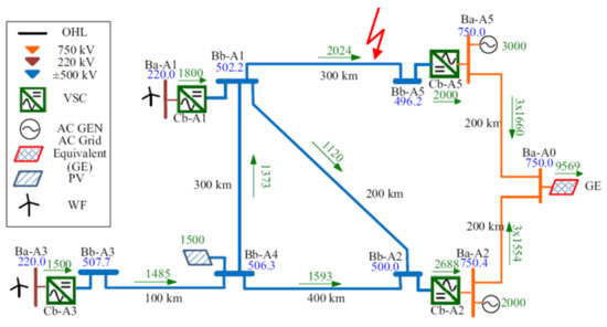
Figure 1.
Reference DC grid for integration of large-scale onshore renewable power generation used for lightning overvoltage propagation. A lightning strike spot is marked by a red arrow [10].
The solar power plant was connected to the grid at Bb-A4. In the reference model, the DC grid was connected to two AC systems, 750 kV and 220 kV, to present the flexibility of the integration. A lightning strike spot is marked in Figure 1 by a red arrow. Two kinds of lightning impulses were considered, the first one attacking the phase conductor with magnitude 20 kA and the latter one with magnitude 200 kA striking the shielding wire. A lightning impulse was subjected to the DC part of the model system with a DC line Bb-A1–Bb-A5, 297 km from the Bb-A1 node and 3 km from the Bb-A5 node. The overvoltage propagation was analyzed in all feeders of the meshed grid. The overvoltage transfer to the AC side was not analyzed in this paper. The parameters of the lightning impulses are summarized in Section 3.3. The lightning current values and models were selected according to [21,22]. In the test topology, the following elements were modeled: overhead lines, tower and grounding systems, insulators including back flash-over phenomenon, and surge arresters. The frequency-dependent models, described in the next section, were applied. The back-flash was simulated with a leader model of discharge. Tower footing impedance as a parameter was changed in a range of 1–300 Ω [23,24]. The AC/DC converter stations were modeled as bipolar two-level half-bridges. On the DC side, the trap filters for 11, 13, 24, and 36 harmonics along with a smoothing choke were implemented. On the AC side, the simplified RC transformer representation was used.
The following scenarios of the lightning impulse propagation were investigated with regard to the impact of surge arresters and polarity of the lightning strike with respect to the DC line polarity (±500 kV): lightning strike to the tower; a lightning strike to DC+ conductor; a lightning strike to middle of the span, including backflash to DC+ conductor; and analysis of footing impedance impact on overvoltages levels during the lightning strike to tower.
3. Simulation System Configuration and Parameters
Computer simulation analysis of lightning overvoltage propagation in HVDC meshed overhead lines were performed in the EMTP/ATPDraw framework. The computer models were constructed according to the state-of-the-art analysis for fast transients [25,26,27,28]. This section presents the description of computer models, the physical phenomena, and their parameters.
3.1. Description of Simulation Test Setup
The simulation test setup had the layout described in the literature as a benchmark test setup STM-DC1 (Figure 1) [10]. A detailed description of the topology is presented in Section 2. The single line diagram of the layout is illustrated in Figure 2. The HVDC stations, OHL connections, substation nodes, and metal oxide overvoltage protection (MOV) are shown. The terminals A1 to A5 are marked on this layout. The red arrow indicates the module where a lightning strike hit was placed.
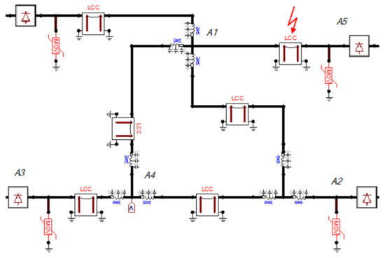
Figure 2.
Single line diagram of the simulated layout based on the reference topology of mHVDC. The red arrow indicated the module where the lightning strike hit was localized.
3.2. Description of the Models Used in the Simulations
This section presents a detailed description of digital models of electrical equipment used in the simulations and physical phenomena that have to be considered in calculations. The following elements of the mHVDC grid have to be modeled in detail in the lightning overvoltage simulations:
- -
- overhead lines (JMarti) [26,27,29];
- -
- towers [26,27,29];
- -
- insulator and backflash phenomena [25];
- -
- surge arrester model [22];
- -
- footing impedance [25,27];
- -
- power electronic converters AC/DC [28,29];
- -
- substation (including harmonic filters 11/13 and 24/36, smoothing inductance), [25,26].
3.2.1. Overhead Lines
The overhead lines were simulated as a distributed parameter model (JMarti procedure) with a frequency-dependent transformation matrix [27,30]. The main frequency at which the parameters were tuned was 500 kHz. This kind of model is suitable for lightning transient analysis. The corona phenomenon was not taken into account in the model. The skin effect in conductors was implemented for the damping of HF components. The used model of the lines simulated the inductive and capacitive couplings between wires. The phase wires were simulated as a single bundle conductor. The length of the particular sections between substations ranged from 100 km up to 400 km (Figure 1). The lightning studies usually consider the detailed model of the overhead line to 10 spans around the point where the lightning hit was implemented; in order to simplify the model of the whole simulated HVDC layout, the 10 span division of OHL was also simulated in the sections with substations. The single span had a length of 350 m and consisted of the tower model with footing impedance and insulators (Figure 5). On the selected insulators, the backflash model was implemented. The planar dimensions of the conductor coordinates are shown in Figure 3 and reflect the 500 kV DC tower design [10]. The ground wires were shorted together at the towers.
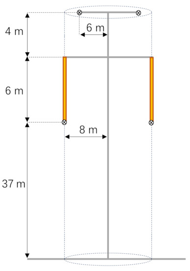
Figure 3.
The 500 kV HVDC tower dimensions used in simulations [10].
3.2.2. Tower
The lightning transients propagating in the overhead line grounding wires reached the towers, which play a role as a discontinuity node for the waves. After reaching the tower, the wave divides into the wave traveling along the conductors and the wave traveling along with the tower to the grounding system. In wave theory, the towers for fast transients act as transmission lines and have to be simulated in this manner. In the ATPDraw, the single-phase distributed parameter line element was used. The surge impedance Zf of the tower can be calculated according to (1) [27]; the tower layout considered in the analyses was threatened as a cylinder with height and diameter corresponding to the tower dimension. For this design, the surge impedance can be described by
where
H—the tower height [m];
r—the radius of the cylinder representing the tower [m].
The distance between particular sections (ground wires–power conductor–grounding system) was simulated as a lossless distributed line connecting the insulators with the footing impedance model. The wave velocity in the tower model was set to 255 m/µs.
3.2.3. Insulator and Backflash Model
The insulators used in the HVDC overhead lines are ceramic cap-and-pin or long rod type [31]. In the fast transient analysis, these types can be simulated as lumped capacitance, despite the DC voltage. In the case of the cap-and-pin type, the model can be extended for every element in the insulator chain, especially for the analysis of single cap failure’s impact on the insulator performance. The capacitance value can be determined due to the length of the insulator and typically reaches values between 80–200 pF depending on the type. For ceramic cap-pin insulators, the capacitance of 100 pF/unit is assumed [25]. The lumped capacitance model has to be extended to the parallel switches used for simulation of the flashover between the conductor and the ground structure of the tower. The switches are controlled by the algorithm describing the leader development method (LDM) [25]; in order to simulate this, the MODELS procedure is used. The LDM for the simulation of the back-flashover across an insulator considers the overvoltage shape, physical properties of the electric discharge mechanism, and properties of the distance between the conductor and tower. This method is based on empirical results. The algorithm used in this model has implemented a differential equation for the length of the leader, which has to be solved during the simulation.
where
K, E0—empirical constants [25];
V(t)—voltage across the insulator [kV];
L—leader length [m];
g—length of the insulator [m].
The condition for the breakdown is met when the leader length L reaches the length of the insulator g; for analyzed cases, the length of the insulator was set to 6 m [31].
3.2.4. Footing Impedance
The purpose of the earthing system is to enable the flow of discharging electric currents into the earth through a metal electrode that is buried in the ground. The impulse impedance of a grounding system is necessary for determining its performance while discharging impulse currents to the ground, as in the case of a lightning strike. During the high-current flow through the electrode in the ground, the soil becomes ionized after reaching the critical ionization field Eg. This phenomenon increases the effective area of the conducting element, which causes the decrease of the footing impedance for high currents [27]. The impulse impedance due to fast transients phenomena also has a non-resistive component related to the magnetic field around the conductors; thus, this model also has to be equipped with a series lumped inductance with the value of 1 µH/m. Impulse resistance Ru of the real earthing system of towers can be approximated by the following formula [25]:
where
Eg ≈ 300–400 kV m−1;
ρe—soil resistivity usually in range of 100–300 Ω m;
Rs—resistance of earthing system for DC current, Ω.
The characteristics of the nonlinear footing impedance used in the simulations, as a function of impulse current, is presented in Figure 4.
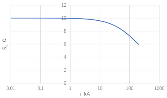
Figure 4.
Relation between footing impedance and the impulse current, calculated for the static resistance Rst = 10 Ω.
The model of elements in the OHL (7) used in the simulations is presented in Figure 5. The individual components of the real system such as lightning stroke (1), insulators (5), backflash (6), and a tower with footing impedance (2, 3, 4) are matched with the model by corresponding numbers.
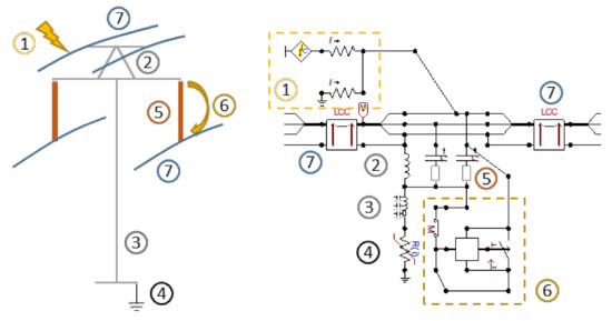
Figure 5.
Model of overhead line (7), insulators (5), backflash (6), and tower with footing impedance (2, 3, 4).
3.2.5. Surge Arresters
The model of surge arrester developed by the IEEE Working Group in 1992 is presented in Figure 6 [22]. Parameters of RLC elements and voltage–current characteristics of nonlinear resistors can be determined from the geometrical parameters of the arrester and nominal parameters, which can be found in catalogs [22]. The idea of this model is to divide the low-frequency components that are filtered by the L1-R1-A1 circuit from high-frequency components that mostly are affected by circuit L0R0-C-A0. The RLC elements do not have the physical meaning of the real metal oxide varistors. Only the capacitance C represents the input capacitance of the real object.
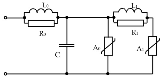
Figure 6.
Model of metal oxide surge arresters worked out by the IEEE [22].
Characteristics of varistors A0 and A1 are represented by the following formulas:
where
U8/20;10—residual voltage with current impulse of times 8/20 μs and maximum value of 10 kA;
Aw0, Aw1—relation approximated with the use of formulas
where
, —constants: = 1.18; = 0.92;
, —currents in the varistors and , A.
Parameters of linear elements L0, R0, L1, R1, and C are respectively expressed by the following dependences:
where
d—height of the varistor column [m];
n—number of parallel varistor columns.
The following parameters of surge arresters were used in the lightning overvoltage simulations in mHVDC at 500 kV [18]:
- ■
- maximum continuous operating voltage (MCOV): 750 kV;
- ■
- lightning impulse protective level (LIPL): 1130 kV (10 kA, 8/20 μs);
- ■
- switching impulse protective level (SIPL): 960 kV (3 kA, 30/60 μs).
3.2.6. Substation
The substation was modeled including most of the equipment according to the rules of the fast transient analysis [25,28]. In the analysis of the lightning overvoltage propagation in HVDC meshed systems, it is necessary to set a proper time resolution that impacts the shortening of step time in the simulation, and on the other hand sets the maximal time to cover the flow and reflections of an electromagnetic wave in the line with the longest connection up to 1000 km. The time of flight for overhead lines between the two farthest stations is approximately 3.3 ms. In comparison to the lengths of the HVDC lines, the sections between elements in the substation have marginal dimensions, and hence the detailed simulation of these distances implies the usage of step time in the range of several nanoseconds. For the optimization of computing time and the complexity of the model, we compressed the substation bus ducts into a single lumped inductance, the power apparatus, which was simulated as a lumped capacitance [25] representing its capacitance to the ground, being also compressed as a single capacitance. This simplification did not impact the analysis results of the lightning overvoltage propagation in the HVDC meshed topology.
The short sections between the elements were modeled as a lumped inductance with the value of 1 µH/m. The substations at the bus nodes were simulated as a lossless line with a surge impedance of 300 Ω and lengths from 20 to 50 m. The smoothing inductance was simulated as a lumped element with L = 2 mH.
3.2.7. Filter Banks
Filter banks are obligatory equipment in HVDC substations that improve the quality of the currents and voltages in the grid. The parameters of the filters are mainly optimized for particular frequencies, especially 11, 13, 24, and 36 harmonics, depending on the design of the converters [32]. The inductor can be modeled in two ways, i.e., as a lumped element that is used in this paper, or as an element with distributed inductance and capacitance for the overvoltage distribution analysis. The lightning transients can stimulate the resonant frequencies of filter banks. The filter banks were placed at the DC+ and DC- output terminals of the substation. The model topology used in the simulations is presented in Figure 7.
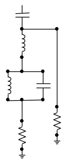
Figure 7.
Model of the double tuned filter for 11 and 13 or 24 and 26 harmonics [32].
3.2.8. Power Electronic Converters AC/DC
The power electronics converters are key components of the HVDC substations. Due to the design and used technology, the power electronics switches are IGBT transistors or thyristors [3]. A detailed model of these elements is necessary for power converter simulation analysis and the testing of the control algorithms. For lightning overvoltage studies, the power electronics switches can be simplified to the diode model or can be simulated as an open or closed ideal switch [28]. The representation of the current state of the ideal switch impacts the transmission and reflection coefficients of traveling waves reaching the substation. The necessary element of every switch in the transient simulation is a snubber that is simulated as a parallel-connected RC element. The topology of the 12-pulse converter [12] was simulated in this paper.
3.2.9. HVDC Voltage Source
The whole model was fed by the ideal direct current voltage source connected to the input of the power electronics converter. The voltage was set to +500 kV and −500 kV.
3.3. Lightning Surge, Lightning Hit on the Line, and Phenomena Related to Fast Transients
This section contains a detailed description of the lightning surge model and the physical mechanism of the lightning hitting the overhead line wires. The description of the fast transient wave propagation mechanism in the power line is presented.
Lightning strikes are unpredicted events occurring in nature. Strikes are characterized by charge flow between clouds and other structures, e.g., overhead lines, buildings, trees, and ground. In theoretical analyses, lightning strike is assumed as a current source with high amplitude exceeding hundreds of thousands of amperes. The CIGRE Working Group [33] has analyzed the measured properties of currents during a lightning strike and has established the statistical set of parameters describing the most important properties of the lightning impulse shape. The further works of various scientists also refer to the analysis of lightning impulse waveform parameters [31]. A total of 90% of lightning is downward negative impulses; in some cases, especially during the winter or during a lightning hit to tall structures (above 100 m height), positive current impulses are also observed [33].
Adequate representation of the lightning impulse current is a topic described in several scientific papers [21,31,33]. The literature provides two main proposals of the lightning current waveforms, the CIGRE and the Heidler model. These two waveshapes are used in lighting protection analysis studies. There are no exact parameters of the peak values, steepness, and time to maximum and time to half value—these parameters are mainly described by the log-normal distribution, and the mean values and dispersion are presented in [21,33]. The Heidler model defined by the IEC 62305-1 is advised for the analysis of lightning hit effects to objects in laboratory conditions [33]. The CIGRE lightning impulse model is proposed as a mathematical description of a real lightning current with two steepness waveshape and maximal steepness close to the peak; this model is suitable for the analysis of the lightning to the overhead lines. The lightning hit study should precisely define the peak values and the proper time parameters for the analyzed waveforms. In this paper, two values of peak current were chosen, i.e., 20 kA and 200 kA. The 20 kA peak value was assumed as the maximal rounded possible current that can hit the power line conductor (Table 1). This current was calculated according to the electro-geometric model (EGM) [33].

Table 1.
Parameters and hit spot localization of the lightning impulses.
The visual representation of the striking distance rs for the 20 kA current and the case with the hit to the overhead line tower is shown in Figure 8. The calculations were performed for the parameters described in the overhead line section and for the Formula (14). The calculations revealed that the maximal current that can hit the power conductor for the analyzed layout was 21.4 kA. Due to the symmetry of the power line, the current was equal for both conductors. The report [34] suggests that the hit to the positive polarity conductor is more probable than the striking to the negative pole. The formula for the calculation of striking distance for a downward lightning strike is
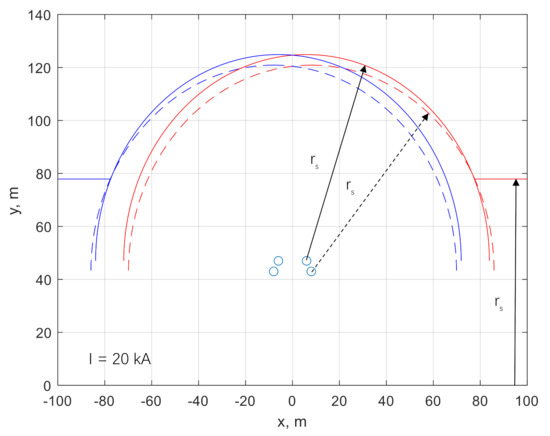
Figure 8.
Lightning striking distance rs is shown for the power conductors (dashed line), ground wires (solid line), and the ground (solid line).
Figure 8 presents the striking distance for the current of 20 kA; the distance rs was drawn around the wires in the 500 kV DC OHL layout and determined from the ground. When the striking distance calculated from the power conductor exceeds the striking distance calculated from the ground wires, the lighting protection might fail, and a strike to the line wires is possible.
The value of 200 kA was chosen as the worst-case scenario for the lightning hitting the tower. The log-normal distributions of the peak current according to CIGRE [33] suggests that the probability of a 200 kA lightning current strike is less than 0.15% (Figure 9).
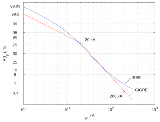
Figure 9.
Probability of first negative stroke lightning current crest value according to CIGRE and IEEE.
The lightning surge transients are categorized as very fast transient overvoltages. For these kinds of waveforms, the power lines are usually threatened as lines with distributed parameters and are subjected to the wave theory. The traveling waves can be transmitted and reflected from the point of discontinuity where two or more surge impedances are connected. In the HVDC meshed networks, the most important issues with the reflection and transmission of overvoltages are in points where two or more HVDC lines are connected; in this case, the resultant surge impedance of the lines is equal to
where
Zz(s)—resultant surge impedance of parallel connected lines;
Zk(s), Zk—surge impedance in Laplace domain and real domain of k-th line connected to the common node;
s—Laplace operator.
Assuming that the two lines have the same surge impedance, we find that the resultant surge impedance is Zfohl/2, which corresponds to the lower amplitude of the transmitted overvoltage. Due to the reflection α and transmission β coefficients given by
The transmitted wave has the amplitude of Uov2 = Uow1/2. The reflected wave is equal to Uov3 = −0.5 Uow1. These calculations do not consider the damping of the traveling wave. Figure 10 presents a simplified view of the point of discontinuity where two or more OHLS are connected (without considering the detailed substations).
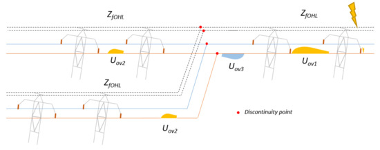
Figure 10.
Division of the traveling wave at the point where two or more lines are connected.
Another issue in the analysis of the fast transients propagation in HVDC lines is the nodes with power electronics switches. In this case, the two main states are available, namely, fully open and fully closed switches. For these instances, the two scenarios for traveling waves are taken into consideration, while a fully open switch traveling wave passes the valve without change of amplitude and a fully closed switch wave reflects from the switch such as for open-end, and also the amplitude rise can be observed.
The traveling electromagnetic waves along power conductors or earthling wires can induct sister traveling overvoltages in parallel conductors. This event exists due to inductive and capacitive couplings between wires. The inducted overvoltage wave has a smaller amplitude than the original overvoltage and can pass the overvoltage protection without changing its shape.
Table 2 presents the values of the parameters for the models used in the simulations.

Table 2.
Summary of the parameters of the models used in the simulation.
4. Results and Discussion
This section contains the simulation results of lightning overvoltages in the meshed HVDC grid. The simulations were performed for different scenarios considering the worst case and the most probable cases:
- Scenario 1: lightning strike to the tower, single backflash to DC+ conductor, Ip = −200 kA;
- Scenario 2: lightning strike to DC+ conductor, Ip = 20 kA;
- Scenario 3: lightning strike to middle of the span, backflash to DC+ Ip = −200 kA;
- Scenario 4: analysis of footing impedance (1 Ω–300 Ω) impact on overvoltage levels during the lightning strike to tower.
The model of the STM1DC [10] layout (Figure 1) developed in the ATPDraw software is presented in the figures below. Due to the complexity of the model, the visualization was divided into parts covering the lightning strike model with backflash, OHL, and towers with footing impedance (Figure 11), the overhead lines of HVDC meshed topology between nodes Bb-A1, Bb-A4, and Bb-A2 (Figure 12) and the last part presents substation with power converters, filter banks, and surge arresters (Figure 13).
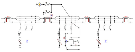
Figure 11.
The lightning current model, backflash model, tower, and line models, part of the network Bb-A1 and Bb-A5 nodes in Figure 1.
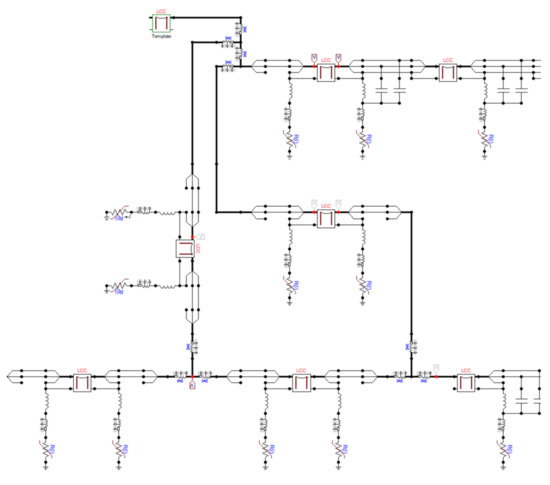
Figure 12.
The meshed part of the HVDC OHL network visible nodes Bb-A1, Bb-A4, and Bb-A2 (Figure 1).
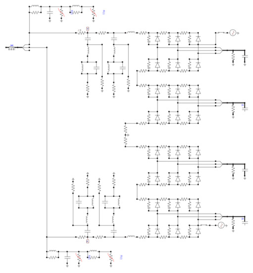
Figure 13.
Substation, power converter, and surge arrester models depicted at node Bb-A5 in Figure 1.
This type of substation was placed at nodes A1, A2, A3, and A5. The analysis covered the impact of overvoltage protection on the overvoltage levels. For the scenarios 1–3, two cases were simulated, with and without surge arresters. The surge arresters were placed at the output terminals of the substations in nodes A2, A3, and A5. The simulations were performed with DC lines charged separately with +500 kV and −500 kV.
The direct lightning strike was localized at a distance of five spans (5 × 350 m) from the A5 substation. At the same distance, the lightning strike to the tower and the backflash were simulated. The analysis of the impact of footing impedance value on the overvoltage levels is described as scenario 4. In this analysis, the resistance of the tower was changed from 1 to 300 Ω, and the overvoltages at the DC+ conductor were observed during a −200 kA lightning strike to the OHL tower. The footing impedance has a strong impact on the overvoltage level at the tower, which reflects on the backflash phenomenon.
The overvoltages were recorded at points A1, A2, A3, A4, and A5 (Figure 2) and at the place where lightning hit OHL or the backflash occurred. The overvoltages were analyzed only at the DC + conductor in the nodes A2, A3, and A5 and were measured at the entrance to the substation. The summary of the maximal overvoltages for scenarios 1–3 is presented in Table 3. The overvoltages are related to the nominal voltage value. Figure 14 and Figure 15 graphically present the overvoltage levels at measurement points for different scenarios. The Figure 16, Figure 17 and Figure 18 presents overvoltages waveforms at measurement points for scenario 1,2,3 respectively. The results of the overvoltage characteristics for scenario 4 are presented in Figure 19.

Table 3.
Maximal overvoltages at selected points for different scenarios without and with surge arresters [p.u].
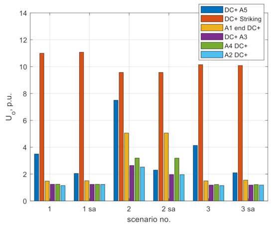
Figure 14.
Comparison of the maximal overvoltages at selected points grouped by the investigated scenarios.
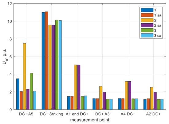
Figure 15.
Comparison of the maximal overvoltages in different scenarios grouped by the measurement point (sa—denotes cases with surge arrester installed).
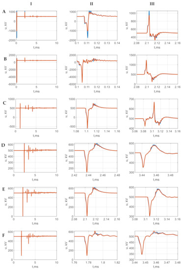
Figure 16.
Voltage waveforms measured at DC+ in scenario 1: lightning hit to tower Ip = −200 kA, with backflash, the case with and without overvoltage protection; A—node A5, B—node where backflash occurred, C—node A1, D—node A3, E—node A4, F—node A2, I—full waveform, II—first maximum, III—second maximum.
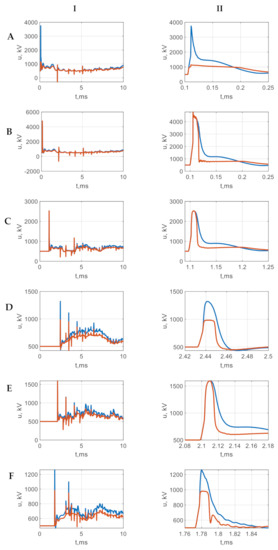
Figure 17.
Voltage waveforms measured at DC+ in scenario 2: lightning strike to DC+ conductor, Ip = 20 kA, the case with and without overvoltage protection; A—node A5, B—node where lightning strikes, C—node A1, D—node A3, E—node A4, F—node A2, I—full waveform, II—first maximum, III—second maximum.
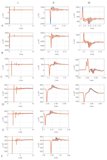
Figure 18.
Voltage waveforms measured at DC+ in scenario 3: lightning strike to middle of span Ip = −200 kA, with backflash, the case with and without overvoltage protection; A—node A5, B—node where backflash occurs, C—node A1, D—node A3, E—node A4, F—node A2, I—full waveform, II—first maximum, III—second maximum.
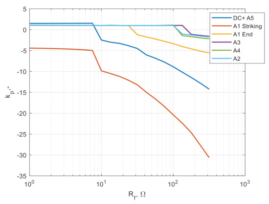
Figure 19.
Characteristics of maximal overvoltages at selected points of the test grid (Figure 1) in relation to footing impedance Rf at spans where lightning strikes; scenario 4: lightning strike to tower Ip = −200 kA, with backflash model, range of Rf = 1 to 300 Ω.
Analysis of the results presented in Table 3 and Figure 14 and Figure 15 show that lightning overvoltages were able to reach every point in the meshed HVDC lines. The highest overvoltages were observed at the point where lightning strikes; at this point, the overvoltage wave splits into two waves that propagate along the conductor. Due to the higher striking current, the higher overvoltages at the place where the back flash occurred were higher than during the direct lightning hit. The lightning transients at the furthest node A3 exceeded the nominal voltage by 14% and were in a form of the short duration disturbance (approximately 20 µs), as shown in Figure 18. These transients can surpass the overvoltage protection and exposure equipment to fast transients.
The comparison between the direct lightning strike and the strike to earthing wire showed the higher overvoltages in case of the shielding failure (scenario 2). In this case, the whole energy of the lightning was directly injected into the conductor, and the electromagnetic wave was not flowing to the ground at nodes where the towers were.
In both analyzed lightning strikes, the division of the wave at the substation nodes A1, A2, and A4 was observed. The overvoltage that passed this node reduced its value due to the lower resultant surge impedance of the parallel connection of two lines.
The applied overvoltage protection in form of the metal oxide surge arresters model only reduced the overvoltages that exceeded the residual voltages for surge arrester (Figure 16, Figure 17 and Figure 18). For overvoltages with longer duration (e.g., direct lightning strike), the MOV placed near the lightning strike also impacted the transients at other points of the meshed grid (Figure 18). This fact was due to the lower amplitude of reflected wave from node A5, which for short distances interfered with the main wave produced by the lightning strike and propagated along the grid. This phenomenon was not observed during the backflash due to shorter times of the disturbance that exceeded the residual voltage of the arrester.
The lightning hit in the middle of the span provided higher overvoltages in comparison to case 1 with the strike directly to the tower (Table 3). During this phenomenon, the lack of the direct current conduction to the ground while striking was observed. The current flowed to the grounding system after reaching the tower by the wave. During this process, the higher lightning current flowing in the earthing wire caused higher overvoltages in the OHL conductor.
The statement of results for scenarios 1–3 is shown in Figure 16, Figure 17 and Figure 18. In all cases, the effect of surge arresters is highlighted, i.e., blue waveform represents the case without overvoltage protection and brown waveform represents the case with installed protection. The rows reflect the measurements at the specified nodes, whereas the columns refer to the full waveform (I—left), first maximum (II—middle), and second maximum (III—right).
4.1. Lightning Strike to Tower, Backflash to DC+ Conductor, Ip = −200 kA—Scenario 1
The comparison of voltage waveforms measured at DC+ conductor in response to lightning hit with magnitude Ip = −200 kA to tower, with backflash effect, is shown in Figure 16 (scenario 1). The protecting effect of surge arresters was visible at node A5, closest to the localization of a striking spot (row A)—overvoltage reduction for the first maximum from 3.5 to 2.05 p.u.
4.2. Lightning Strike to DC+ Conductor, Ip = 20 kA—Scenario 2
The comparison of voltage waveforms measured at DC+ conductor in response to lightning hit with magnitude Ip = −20 kA to DC+ conductor is shown in Figure 17 (scenario 2). The overvoltage reduction for the first maximum from 7.5 to 2.35 p.u. was visible at terminal A5 (row A) with applied surge arrester protection. The attenuation effect was also visible at far nodes A3 (row D) and A2 (row F). The overvoltage reaching the A3 node passed two terminals in the multiterminal topology of mHVDC.
4.3. Lightning Strike to Middle of the Span, Backflash to DC+, Ip = −200 kA—Scenario 3
The comparison of voltage waveforms measured at DC+ conductor in response to a lightning strike to middle of span with magnitude Ip = −200 kA with backflash is shown in Figure 18 (scenario 3). The overvoltage reduction for the first maximum from 4.13 to 2.1 p.u. was visible at terminal A5 (row A) with applied surge arrester protection. Overvoltage also in this case reached the far end terminal A3 where the corresponding attenuation decreased to 1.97 from 2.64 p.u. due to installed surge arresters.
4.4. Analysis of Impact of Footing Impedance on Overvoltages Levels during Lightning Strike to Tower
The simulation results of maximal overvoltage in relation to the footing impedance are presented in Figure 19. The results determined the overvoltage coefficient kp referred to the nominal voltage. The change of the grounding resistance is a natural process during the lifetime of the towers. The main impact on the ground resistance change has soil resistivity that changes its values due to atmospheric conditions.
As can be seen in Figure 19, the value of 8 Ω was critical for analyzing the 200 kA lightning strike. The simulation results showed that for higher footing impedance above 8 Ω, the backflash occurred and provided the voltage transients in the meshed grid that were propagated along the conductors. Hence, the higher the footing impedance Rf, the higher the propagating overvoltages.
5. Conclusions
This paper reports on the propagation of lightning overvoltages in multiterminal HVDC grids, applying a common reference platform. In the simulations, various configurations were considered, analyzing lightning strike hitting both shielding wire and DC conductor. In the first case, the lightning to the tower as well as to the middle of the span was evaluated, including the backflash effect on insulators. The worst-case results showed that the overvoltages at the nearest substation terminals without overvoltage protection can reach up to 7.5 p.u.; after applying the surge arresters, the overvoltages can be reduced by 70% to 2.3 p.u., which is mainly dictated by characteristics of surge arrester. The corresponding case with direct lighting strike produced overvoltages at the level of 3.5 p.u., and after applying the surge arresters, reduction by 4.2% to 2.05 p.u. was observed. The main focus of the paper was on the wide-area propagation of the overvoltages in the meshed grid. An interesting observation was the revelation of the effects of lightning at the far end of the analyzed grid (e.g., terminal A3), propagating through the multiterminal and long-distance connections. The most severe scenario, which in this case was a direct hit to the conductor, revealed that overvoltages at the furthest node of the meshed grid can reach up to 2.64 p.u. in cases without overvoltage protection. The overvoltage attenuation or amplification is also strongly related to the impedance transformation at the terminal nodes and corresponding wave effects. The influence of overvoltage protection was analyzed in the paper. The surge arresters were placed at the HVDC station terminals and the incoming overvoltage levels were compared. The maximal overvoltages occurred naturally at the lightning strike hitting spot and both terminals of the subjected line, but they were observed also at remote terminals (e.g., A4) at an elevated level; in every simulated case, lightning strike produced transients reaching the furthest point for which values exceed 14% the nominal voltages. The comparison of direct tower hit versus the middle of the span had a rather small difference at the distant nodes. In a parameterized analysis, the effect of tower footing impedance was evaluated. The critical value of footing impedance with respect to the overvoltage level was calculated at different terminals. The analyzed configuration revealed that footing impedance higher than 8 Ω can be the reason for the backflash phenomenon during lightning strikes to shielding wire with maximum values of 200 kA.
The presented analysis, based on an exemplary meshed HVDC grid, underlines the importance of the insulation coordination studies and system security studies with respect to the localization of overvoltage protection systems.
Author Contributions
Conceptualization, M.F. and M.K.; methodology, M.F., J.F. and M.K.; software, M.K.; validation, M.F. and J.F.; investigation, M.F., J.F. and M.K.; writing—original draft preparation, M.F., J.F. and M.K.; writing—review and editing, M.F. and M.K. All authors have read and agreed to the published version of the manuscript.
Funding
This research received no external funding.
Institutional Review Board Statement
Not applicable.
Informed Consent Statement
Not applicable.
Data Availability Statement
Not applicable.
Conflicts of Interest
The authors declare no conflict of interest.
Nomenclature
| AC | alternating current |
| AIS | air insulated substation |
| ATP | alternative transient program |
| CIGRE | Conseil International des Grands Reseaux Electriques |
| DC | direct current |
| EGM | electro-geometric model |
| EMTP | electromagnetic transient program |
| HF | high-frequency |
| HVDC | high-voltage direct current |
| IEC | International Electrotechnical Commission |
| IEEE | Institute of Electrical and Electronics Engineers |
| IGBT | insulated gate bipolar transistor |
| LDM | leader development method |
| LIPL | lightning impulse protective level |
| MCOV | maximum continuous operating voltage |
| mHVDC | meshed high-voltage direct current |
| MOV | metal oxide varistor |
| OHL | overhead line |
| SIPL | switching impulse protective level |
| VSC | voltage source converter |
References
- CIGRE Technical Brochure No 804, DC Grid Benchmark Models for System Studies; WG B4.72; CIGRE: Paris, France, 2020.
- Bucher, M.K.; Wiget, R.; Andresson, G.; Franck, C.H. Multiterminal HVDC Networks–What is the Preferred Topology? IEEE Trans. Power Deliv. 2014, 29, 406–413. [Google Scholar] [CrossRef]
- Schönleber, K.; Oudallov, A.; Krontiris, A.; Lundberg, P. Opportunities for Embadded High-Voltage Direct Current. IEEE Power Energy Mag. 2020, 18, 58–63. [Google Scholar] [CrossRef]
- An, T.; Tang, G.; Wang, W. Research and application on multi-terminal and DC grids based on VSC-HVDC technology in China. High. Volt. 2017, 2, 1–10. [Google Scholar] [CrossRef]
- Franck, C.M. HVDC Circuit Breakers: A Review Identifying Future Research Needs. IEEE Trans. Power Deliv. 2011, 26, 998–1007. [Google Scholar] [CrossRef]
- Bucher, M.K.; Franck, C.M. Fault Current Interruption in Multiterminal HVDC Networks. IEEE Trans. Power Deliv. 2016, 31, 87–95. [Google Scholar] [CrossRef]
- Haileselassie, M.; Uhlen, K. Power System Security in a Meshed North Sea HVDC Grid. Proc. IEEE 2013, 101, 978–990. [Google Scholar] [CrossRef]
- Vrana, T.K.; Yang, Y.; Jovcic, D.; Dennetiere, S.; Jardini, J.; Saad, H. The Cigre B4 DC Grid Test System. Electra 2013, 270, 10–19. [Google Scholar]
- An, T.; Zhou, X.; Han, C.; Wu, Y.; He, Z.; Pang, H.; Tang, G. A DC Grid Benchmark Model for Studies of Interconnection of Power Systems. CSEE J. Power Energy Syst. 2015, 1, 101–109. [Google Scholar] [CrossRef]
- An, T.; Han, C.; Wu, Y.; Tang, G. HVDC grid test models for different application scenarios and load flow studies. J. Mod. Power. Sys. Clean Energy 2017, 5, 262–274. [Google Scholar] [CrossRef]
- Florkowski, M.; Furgał, J. High Frequency Methods for Condition Assessment of Transformers and Electrical Machines; Publishing House AGH: Kraków, Poland, 2013; ISBN 978-83-7464-614-7. [Google Scholar]
- Florkowski, M.; Furgał, J.; Kuniewski, M. Propagation of overvoltages in the form of impulse, chopped and oscillating waveforms in transformer windings–time and frequency domain approach. Energies 2020, 13, 304. [Google Scholar] [CrossRef]
- Florkowski, M.; Kuniewski, M.; Zydroń, P. Partial Discharges in HVDC Insulation with Superimposed AC Harmonics. IEEE Trans. Dielectr. Electr. Insul. 2020, 27, 1875–1882. [Google Scholar] [CrossRef]
- Florkowski, M.; Furgał, J.; Kuniewski, M.; Pająk, P. Overvoltage exposures of transformer insulation systems during impulse voltage tests and in operating conditions (in Polish). Electr. Rev. 2016, 10, 100–103. [Google Scholar]
- IEC 60071-2 Insulation Co-Ordination—Part 2: Application Guidelines; IEC: Geneva, Switzerland, 2018.
- IEC 60071-4 Insulation Co-Ordination—Part 4: Computational Guide to Insulation Co-Ordination and Modelling of Electrical Networks; IEC: Geneva, Switzerland, 2004.
- Goertz, M.; Wenig, S.; Gorges, S.; Kahl, M.; Beckler, S.; Christian, J.; Suriyah, M.; Leibfried, T. Lightning Overvoltage in a HVDC Transmission System comprising Mixed Overhead-Cable Lines. In Proceedings of the International Conference on Power System Transients (IPST’17), Seoul, Korea, 26–29 June 2017. [Google Scholar]
- Asif, M.; Lee, H.; Park, K.; Shakeel, A.; Lee, B. Assessment of Overvoltage and Insulation Coordination in Mixed HVDC Transmission Lines Exposed to Lightning Strikes. Energies 2019, 12, 4217. [Google Scholar] [CrossRef]
- Lennerhag, O.; Lundquist, J.; Engelbrecht, C.; Karmokar, T.; Bollen, M.H.J. An Improved Statistical Method for Calculating Lightning Overvoltages in HVDC Overhead Line/Cable Systems. Energies 2019, 12, 3121. [Google Scholar] [CrossRef]
- Karmokar, T.; Lennerhag, O. Simplified Approach for Investigating Overvoltages in DC Cables in a ±320 kV Symmetrical Monopolar HVDC System. In Proceedings of the International Symposium on High Voltage Engineering (ISH’19), Budapest, Hungary, 26–30 August 2019; pp. 1401–1412. [Google Scholar]
- Furgał, J. Influence of Lightning Current Model on Simulations of Overvoltages in High Voltage Overhead transmission Systems. Energies 2020, 13, 296. [Google Scholar] [CrossRef]
- IEEE Working Group 3.4.11. Modelling of metal oxide surge arresters. IEEE Trans. Power Deliv. 1992, 7, 302–307. [Google Scholar] [CrossRef]
- Pastromas, S.A.; Naxakis, I.A.; Xerra, S.I.; Koutras, K.N.; Pyrgioti, E.C. Evaluation of Wind Turbine Earthing System. In Proceedings of the International Symposium on High Voltage Engineering (ISH’19), Budapest, Hungary, 26–30 August 2019; pp. 316–328. [Google Scholar]
- Podporkin, G.V. Improvement of Overhead Transmission Lines Lightning Protection by Line Arresters with Separate Groundings and Shielding Wire Fixed at Insulation Racks. In Proceedings of the International Symposium on High Voltage Engineering (ISH’19), Budapest, Hungary, 26–30 August 2019; pp. 1180–1191. [Google Scholar]
- Modeling guidelines for fast front transients. IEEE Trans. Power Deliv. 1996, 11, 493–506. [CrossRef]
- CIGRE Technical Brochure No 63, Guidelines for Representation of Network Elements When Calculating Transients; CIGRE: Paris, France, 1990.
- Ametani, A.; Kawamura, T. A method of a lightning surge analysis recommended in Japan using EMTP. IEEE Trans. Power Deliv. 2005, 20, 867–875. [Google Scholar] [CrossRef]
- Gole, A.; Keri, A.; Kwankpa, C.; Gunther, E.; Dommel, H.; Hassan, I.; Marti, J.; Martinez, J.; Fehrle, K.; Tang, L.; et al. Guidelines for modeling power electronics in electric power engineering applications. IEEE Trans. Power Deliv. 1997, 12, 505–514. [Google Scholar] [CrossRef]
- Høidalen, K.K.; Prikler, L.; Peñaloza, F. ATPDRAW Version 7.2 for Windows Users’ Manual, Release No. 1.0. 2020.
- ATP-EMTP Rule Book; Canadian/American EMTP User Group, Bonneville Power Administration: Portland, OR, USA, 1987.
- Salimi, M.; Barthold, L.; Woodford, D.; Gole, A. Prospects for Compaction of HVDC Transmission Lines; CIGRE-IEC Colloquium: Montréal, QC, Canada, 2016. [Google Scholar]
- CIGRE. DC Side Harmonics and Filtering in HVDC Transmission Systems; Technical Brochures 811; CIGRE: Paris, France, 2020. [Google Scholar]
- CIGRE. WG 33-01 of Study Committee 33, Overvoltages and Insulation Coordination: Guide to Procedure for Estimating the Lightning Performance of Transmission Lines; Publ. No 63; CIGRE: Paris, France, 1991. [Google Scholar]
- Rodrigues, E.; Pontes, R.S.T.; Bandeira, J.; Aguiar, V.P.B. Analysis of the Incidence of Direct Lightning over a HVDC Transmission Line through EFD Model. Energies 2019, 12, 555. [Google Scholar] [CrossRef]
Publisher’s Note: MDPI stays neutral with regard to jurisdictional claims in published maps and institutional affiliations. |
© 2021 by the authors. Licensee MDPI, Basel, Switzerland. This article is an open access article distributed under the terms and conditions of the Creative Commons Attribution (CC BY) license (https://creativecommons.org/licenses/by/4.0/).