Article

Direct Analytical Modeling for Optimal, On-Design Performance of Ejector for Simulating Heat-Driven Systems

1
Department of Mechanical Engineering, National University of Singapore, Singapore 117575, Singapore
2
Department of Mechanical Engineering, University of Engineering and Technology Lahore, Lahore 54000, Pakistan
3
School of Chemical Engineering, Yeungnam University, Gyeongsan 712-749, Korea
4
Department of Mechanical and Construction Engineering, Northumbria University, Newcastle Upon Tyne NE1 8ST, UK
*
Authors to whom correspondence should be addressed.
Energies 2021, 14(10), 2819; https://doi.org/10.3390/en14102819
Submission received: 10 April 2021 / Revised: 5 May 2021 / Accepted: 8 May 2021 / Published: 14 May 2021

Abstract

:
This paper describes an ejector model for the prediction of on-design performance under available conditions. This is a direct method of calculating the optimal ejector performance (entrainment ratio or ER) without the need for iterative methods, which have been conventionally used. The values of three ejector efficiencies used to account for losses in the ejector are calculated by using a systematic approach (by employing CFD analysis) rather than the hit and trial method. Both experimental and analytical data from literature are used to validate the presented analytical model with good agreement for on-design performance. R245fa working fluid has been used for low-grade heat applications, and Engineering Equation Solver (EES) has been employed for simulating the proposed model. The presented model is suitable for integration with any thermal system model and its optimization because of its direct, non-iterative methodology. This model is a non-dimensional model and therefore requires no geometrical dimensions to be able to calculate ejector performance. The model has been validated against various experimental results, and the model is employed to generate the ejector performance curves for R245fa working fluid. In addition, system simulation results of the ejector refrigeration system (ERS) and combined cooling and power (CCP) system have been produced by using the proposed analytical model.

1. Introduction

More than 60% of the energy produced by fossil fuels is dissipated as wasted heat, from which more than 50% is low-grade heat energy with temperatures lying lower than 275 °C [1,2,3]. Low-grade heat is also available from green energy resources like geothermal [4] and solar energy [5]; hence, utilizing low-temperature thermal energy leads to an increased thermal efficiency [6] and in the percentage of green energy [7]. Buildings, primarily for HVAC, consume about 40% of the world’s primary energy and are responsible for about one-third of global CO2 emissions [8]. The vapor compression cycle, VCC, a refrigeration technology, is mostly used for HVAC all over the world [9]. Rapid urbanization and an increase in the quality of life have been increasing the global cooling demand. According to the UN, by 2050, about 70% of the world’s population will be living in cities [10], and the world’s cooling and air-conditioning demand is expected to go up by 300% by the year 2050 [11]. Low-quality heat-driven cooling systems present a great solution to meet the challenge of a rapid increase in demand for air-conditioning, especially for tropical areas, for which harnessing low-grade heat is more challenging [12,13]. Low-grade heat-driven cooling and power systems can be used as a replacement to the traditional systems [14]. Among the myriad devices that can readily be deployed to derive useful energy from waste heat streams is the jet pump or ejector [15]. Ejectors or jet pumps have been explored for harnessing low-temperature heat to drive technologies such as ejector refrigeration system (ERS) [16,17,18,19,20], ejector-enhanced Rankine cycle (EORC) [21] and combined cooling and power system (CCPS) [22,23,24]. ERSs generally have lower co-efficient of performance (COP) values as compared to the conventional vapor compression systems or absorption refrigeration systems [25] because of generally lower quality of heat input and the nature of ejector’s intrinsic thermal operations, which involve energy losses due to entrainment, mixing and compression shocks.
The entrainment ratio (ER) of an ejector is the ratio of the mass flow rate of suction fluid to the mass flow rate of motive fluid. A higher value of ER means that the ejector is operating more efficiently because the ejector is able to compress more fluid (suction) for the same amount of motive fluid. For the ejector simulations, we need to calculate the ejector ER for the available working conditions. The area-ratio (AR) of ejectors is termed as a ratio of the mixing-chamber cross-sectional area to the throat area of the primary-nozzle, and it is considered to be the most important and sensitive parameter which affects the ejector performance [26]. As reported by various publications [20,27,28,29], the AR needs to be optimized for every new set of operating conditions to maintain the ejector operating at maximum efficiency. The nozzle exit position (NXP) is also an important parameter for the ejector, which may affect the ER value by 40% [26,28,30,31,32].
The detailed ejector geometric optimization can be studied by either experimental works or by computational fluid dynamics (CFD). Zhang et al. [23] conducted CFD investigation for studying the transport processes in ejectors while focusing on quantifying the energy losses. Scott et al. [25] employed a CFD analysis for ejector designing refrigeration application and investigated the effect of altering the conditions on the entrainment ratio (ER) and critical pressures.
Keenan et al. [33] developed a model of ejectors, which is a one-dimensional (1 D) model that assumes mixing to happen at constant pressure. This model worked as a foundation for the models developed by Chen et al. [29] and Huang et al. [34]. For the pressure to remain constant during mixing, it is essential for the exit plain of the primary nozzle to be in front of the mixing chambers’ constant area section. Keenan’s model, however, did not take into consideration the choking of suction fluid [35]. Huang et al. [34] took into consideration the double-choking and improved the 1-D model. They claimed that the position of secondary fluid choking is at the upstream of the constant-area starting section of the mixing chamber. When the motive fluid comes out of the convergent-divergent nozzle exit section, it keeps expanding without mixing with the entrained fluid. Because of the expanding and spreading of motive fluid and the converging section of the chamber, an imaginary duct forms, which speeds up the suction-flow to sonic speeds [35]. Huang’s model is an iterative model and utilizes isentropic expansion relations of thermodynamics. Additionally, it needs the primary-nozzle dimensions as inputs to be able to do the calculations. Huang validated his 1-D analytical model with his experimental results with ±15% deviation.
In Chen’s model [29], the choking of secondary flow has also been taken into consideration considered, but this model is a 0-D model, and hence, it does not require an ejector geometric design to obtain the ER of the ejector. Chen’s model has been derived from energy and momentum relations and needs two-step iterations for two parameters (constant mixing pressure and ER values) to get the ER values. The need to do two-step iterations makes it a more complex model and is not able to calculate off-design conditions.
For ERSs, many published works have recommended the use of R245fa as a suitable working fluid [3,32,36,37,38], and the work presented in this paper also uses R245fa, which is a dry and non-flammable fluid, due to the suitability of its pressure and temperature values for low-quality heat utilization and zero ozone depletion potential.
This paper presents a novel analytical model of ejector employing a direct-calculation method that does not need iterations. This model has been implemented in Engineering Equation Solver (EES) [39] and utilizes its built-in thermodynamic characteristics of the working fluids. Simulations and Experimental data from the literature have been used for validation of this model, and good agreements have been reached. Because of the direct-single step calculation of ER, this model may be incorporated into the system’s (ERS/EORC/CCP) models and could be easily used for system simulations and optimizations. The performance curves of ejectors for many different working fluids may be generated by using this model. The presented model employs CFD analysis to compute the ejector efficiencies (nozzle, mixing and diffuser) rather than using the hit-and-trial method for finding out the ejector efficiencies, which has been used by the iterative models of Chen et al. [29] and Huang et al. [34]. The proposed analytical model is a direct model that needs input from the CFD only once. Contrary, if experimental or CFD simulations are used for system-level simulations, it is almost impossible to conduct system optimization because it needs many runs. Once the CFD analysis has been done and suitable ejector efficiencies have been found for the ranges of operating conditions, the analytical model runs independently in a direct way. Experimental data from literature [34] has been utilized for validating the CFD model, and the validated CFD model is then employed for ejector geometry optimization. Therefore, the on-design performance of the optimized ejector geometry can be obtained with CFD, and these results are then used to obtain the values of the ejector efficiencies (ηn, ηm and ηd) for the analytical model. The novelty of the presented work is highlighted below:
  • A new analytical model is proposed, which is a direct model and does not need iterative processes to get performance prediction;
  • This model uses a systematic approach by employing CFD analysis rather than hit-and-trial approach to calculate the ejector efficiencies;
  • The proposed model agrees with data published by various researchers for on-design prediction of ejector performance;
  • Ejector performance curves produced with the model are presented;
  • System simulation and comparison results for ERS and CCP system have been produced;
  • The practical applications of the proposed model involve the designing and optimization of thermal systems involving ejectors, for example, ejector refrigeration systems, ejector enhanced ORC systems and other hybrid systems.

2. The Analytical Modeling of Ejector

As discussed, ejectors are thermal compressors that use thermal energy to compress fluids. The high-pressure primary (or motive) fluid enters the primary (convergent-divergent) nozzle and expands to supersonic speed, and after leaving the nozzle, it keeps expanding and generates low pressure, which induces the secondary (or suction) flow at low pressure. The two streams keep mixing in the mixing chamber, and while mixing, the secondary fluid is accelerated, and the primary fluid is decelerated. In the mixing chamber, the back (delivery) pressure for the mixed flow is reached with a compression shock wave and through further pressure recovery in the diffuser.
As the preliminary works for the development of this new model, two of the renowned ejector models were developed in EES. These two models are: (i) 1-D model by Huang et al. [34] and (ii) 0-D model by Chen et al. [29]. The developed EES models of both of these works are presented in the Appendix A.
The structure of the ejector is shown in Figure 1. The velocity and pressure variation at different positions inside the ejector are also shown. The primary fluid is shown with red colour, and the secondary fluid is shown in blue colour. The primary nozzle inlet pressure is denoted by Pg or P1, while the secondary fluid inlet pressure is denoted by Pe, where e denotes evaporator from where the secondary fluid enters. At Section 2, the throat of the nozzle, the primary fluid reaches the sonic speed. At Section 3, the two fluids are assumed to have totally mixed to have the same speed. At Section 4, the mixed flow experiences a compression shock. The delivery pressure is denoted by Pc, where c is for the condenser where the mixed fluid is delivered.
Figure 2 is showing the change in entropy and enthalpy values at different ejector positions. Pmc indicates the pressure of the mixing chamber, whose value is supposed to be constant up to the positioning where shock occurs (Section 4). At Section 2, the primary and secondary fluids are starting to mix at constant pressure. ηn indicates the nozzle isentropic efficiency and accounts for the losses in the convergent-divergent nozzle while the mixing and compression (shock and diffuser) losses are accounted by the efficiencies ηm (mixing) and ηd (diffuser), respectively.
Referring to the two figures above, the assumptions and short descriptions of the model are:
  • The model is developed to simulate the on-design, optimum ER values for given conditions. Both motive and suction flows acquire chocked conditions for the critical delivery pressure.
  • This model is independent of the size of the ejector, that is, it is non-dimensional or 0-D model and is not able to simulate off-design performance.
  • It is assumed that the ejector operates at adiabatic and steady-state conditions.
  • Both the inlet velocities are assumed to be negligible, that is, stagnation condition is assumed.
  • Both the inlets (motive and suction) are assumed to be at a saturated vapor state.
  • The speed at the exit of the ejector is assumed to be negligible.
  • The diffuser efficiency accounts for the whole compression (pressure gain) process loss due to shock and diffuser section.
  • At Section 2, suction fluid is considered to be chocked, and therefore, it is possible to find the pressure of the constant area mixing section by utilizing the thermodynamic relations.
  • For the motive fluid’s expansion calculations, its k-value (exponent for compression and expansion) has been taken as constant.

2.1. Governing Equations

The modelling in EES and the computation procedure has been developed for direct simulation of the ejector. First of all, operating conditions are entered in the form of equations. These input parameters are Pg, Pe, Pc, ηn, ηm and ηd. That is:
P g = P 1
P e = P 6
Because the generator and evaporator pressure are known, the enthalpy and entropy values at states 1 and 6 can be calculated. The k-value is assumed relative to point 6, that is, for the suction flow inlet.
Because there are choking conditions at Section 2 (with pressure Pmc), the adiabatic equation for suction fluid can be used. That is:
P 6 P mc = ( 1 + k 1 2 ) ( k k 1 )
Now that the pressure Pmc is calculated, the values of h6,is and h1,is may be calculated. For stagnation inlet conditions, by employing the energy conservation, the velocities Vp,2 and Vs,2 can be found as:
V p , 2 = 2   η n ( h 1 h 1 , is )
V s , 2 = 2   ( h 6 h 6 , is )
In Equation (4), the expansion losses are ignored because of the minute pressure difference between the mixing chamber and P6 and Pmc. Referring to Figure 1, at position 3, both the fluids have the same speeds, and at position 4, shock occurs, the ER is:
ER = m e m g
With the application of momentum conservations at positions 2 and 4, refer to Figure 3, a relation for velocity V4 can be obtained.
Section 2 and Section 4 have constant area and pressure. For the same inlet conditions, the mixing efficiency (ηm), which is the ratio of ideal and actual kinetic energies, becomes:
η m = Actual   K . E .   at   exit Ideal   K . E .   at   exit = V 4 2 V 4 ,   ideal 2
Momentum balance for positions 2 to 4 gives:
V 4 = η m   ( V p , 2 + ( ER )   V s , 2 1 + ER )
The application of energy balance starting from both inlets up to position 4 gives the value of h4 because both inlets’ velocities are negligible, hence:
h 4 = h 1 + ( ER )   h 6 1 + ER V 4 2 2
Applying the energy balance from position 4 and up to the ejector exit, we get another equation that relates V4 and h4;
V 4 = 2   ( h 4 , is h 4 ) η d
Simultaneous solution of Equations (4), (5), (8) and (10), and elimination of the velocity variables, the formular of ER is obtained as:
ER = 2 η n ( h 1 h 1 , is )   2 ( h 4 , is h 4 ) / ( η m η d )   2 ( h 4 , is h 4 ) / ( η m η d ) 2 ( h 6 h 6 , is )
This is the relation employed to calculate the ER, but its implementation is not straight forward, and the challenge is to model this equation such that we can solve this equation in a single step rather than iteratively, which has been achieved by this computational procedure. Additionally, in order to use this equation, we must know the values of all of the unknowns, including the ejector efficiencies.

2.2. Computational Procedure

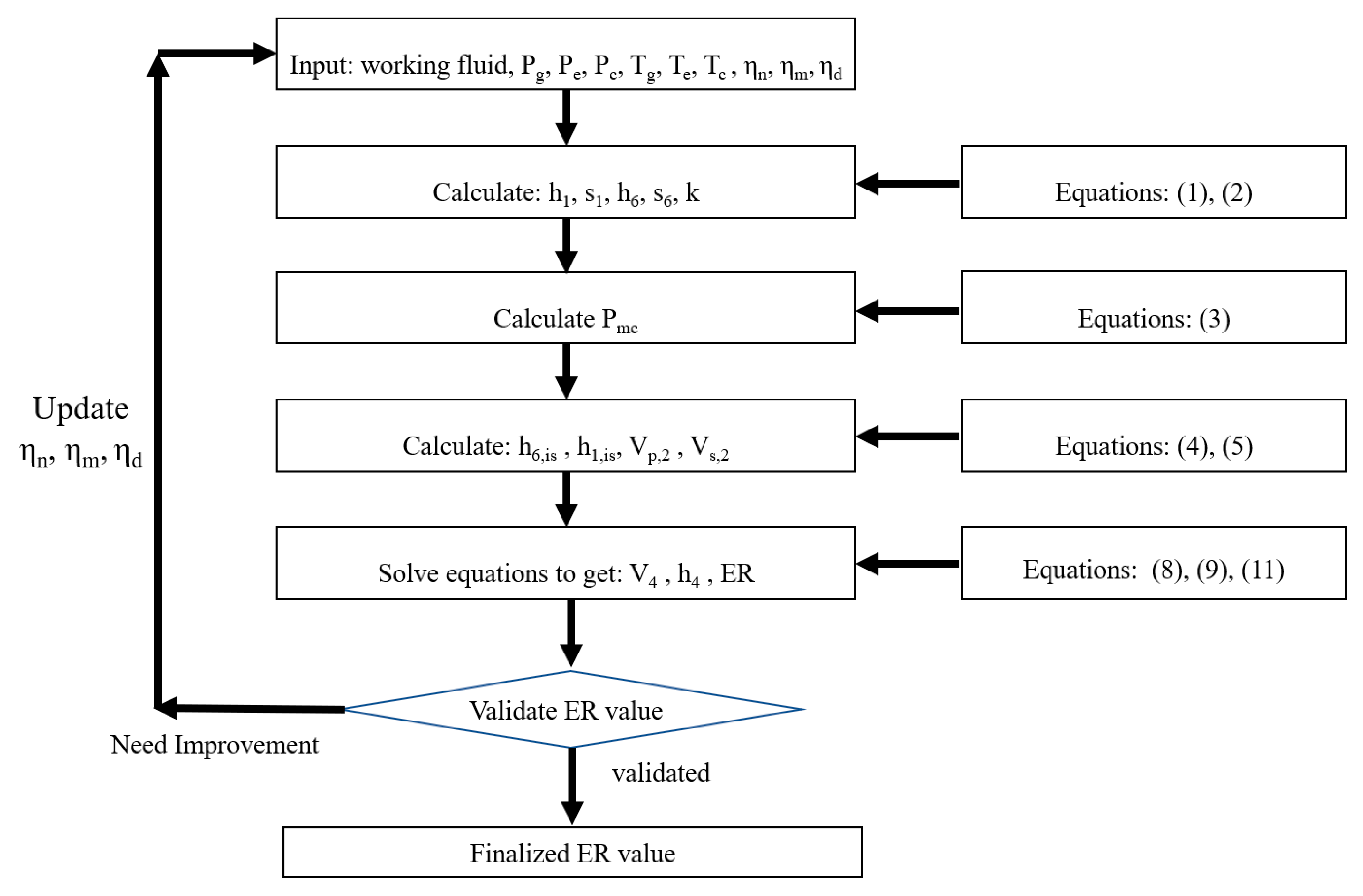
Figure 4 shows the computational procedure to implement the modelling in EES. First of all, the input parameters are entered into the EES by using the corresponding equations. Then, the pressure Pmc is calculated by Equation (3), which helps to determine the values of h6,is and h1,is, and then velocities at position 2 are calculated. The three unknown variables at this stage are h4, V4 and ER, which are obtained by simultaneous solution of Equations (8), (9) and (11), which is a single step.

2.3. Finding the Ejector Efficiencies

Many researchers [26] indicate that while the mixing efficiency and diffuser efficiency may vary with the conditions, the nozzle efficiency may be assumed to remain constant. This analytical model relies on CFD analysis by employing a systematic approach to estimate the values of ejector efficiencies rather than relying on limited data from experiments or by using the hit and trial method. This model gets the efficiencies from CFD by first designing an ejector that gives the best performance for optimized geometry in CFD. The obtained values of efficiencies have been validated by comparing the results with published data for R245fa working fluid by Zheng et al. [24] and Federico et al. [41]. For example, when the ejector geometry was optimized with CFD, and its simulation data is obtained by post-processing, the velocity of flow at the section just behind the section where the shock happens is 235 m/s, and the speed at the entrance of the constant area is 252 m/s. By applying the mixing efficiency definition mentioned in the previous modelling section, the value of mixing efficiency is obtained as 0.87.

2.4. CFD Modelling of Ejectors

In FLUENT (ANSYS) [42], 2D axisymmetric modelling has been employed to conduct the CFD analysis of an ejector. The governing equations (mass, momentum and energy) are solved by ANSYS-FLUENT by discretization of the control volumes of simulation space. For the validation of modelling methodology, the design of published works (Model AG1) [34] has been used, which is shown in Figure 5. The meshing is developed as a structured mesh with 9940 elements. In structured mesh, each dimension is divided into small sections and element size is the length of a single section. In the mesh independence test, it was found that when the element size was reduced from 0.075 mm to 0.05 mm, the ER values were varying and converging but when the element size was further reduced from 0.05 mm to 0.03 mm, the change in ER was only 0.2%; therefore, 0.05 mm element size was selected as suitable size of the element.
Quadrilateral, structured mesh has been used, and the upwind second order scheme has been implemented in the axisymmetric model, which has been shown to give similar output at 3D models but with significantly less computational costs for relatively simpler (not extreme operating conditions) ejector simulations [28,43]. For the solver settings, a pressure-based outlet and inlet boundary-conditions have been employed with the k-ε realizable method for turbulence field calculations, which is reported to capture better results neat boundaries for pressure variation [44,45,46]. For a high-compression fluid flow, a density-based solver is preferred, but with the advancement in numerical model coding, a pressure-based solver is also able to handle the high compression fluid flow without divergence in solution. Because the working conditions for low-grade heat utilization are not in the high-compression range, the pressure-based solver has been used [47,48]. The refrigerant has been taken as the ideal gas with constant Cp values, which has also been employed by many other researchers [34,49]. While the proposed analytical model of the ejector is using the real gas properties by using the built-in data of the working fluids in the EES software, for the CFD model, as recommended by many researchers, the ideal gas condition is used. While using the ideal gas relations in FLUENT, a good agreement of CFD results with experimental results has been obtained. This is discussed further in the results section. The summary of the settings used in FLUENT is given in Table 1. The CFD results are in good agreement with various published results, and the detailed validation is provided in the results and discussion section.

3. Results and Discussion

3.1. Validation of CFD Modelling

For validation of the CFD model, an ejector for which geometric design and experimental results are available in literature [34] has been modelled in ANSYS-FLUENT. Figure 6 is showing the results of CFD modelling in the form of Mach contours. The ER obtained for the CFD results shown in the figure is 0.39357, while the experimental ER value reported by [34] is 0.3922, and the ER value reported by another simulation work [25] is 0.398. This means that the results are in very good agreement with experiments [34] and the published simulation results [25] with a percentage difference of 0.4% and 1.1%, respectively. As shown, the motive fluid attains sonic velocity (M = 1) at the throat of the nozzle. After the shock, the velocity is jumping suddenly below the sonic velocity (M < 1) and then further decelerates to the condenser pressure.
When the suction fluids come in contact with primary fluid, which is at supersonic speed, it accelerates because of the shear layer between them. Figure 7 shows this in the form of velocity vectors changing their colours. It can be noted that the motive fluid keeps accelerating (increasing its speed) even after exiting the nozzle. After the shock in the diffuser section, the velocity is suddenly dropped, which is indicated by light blue colour.
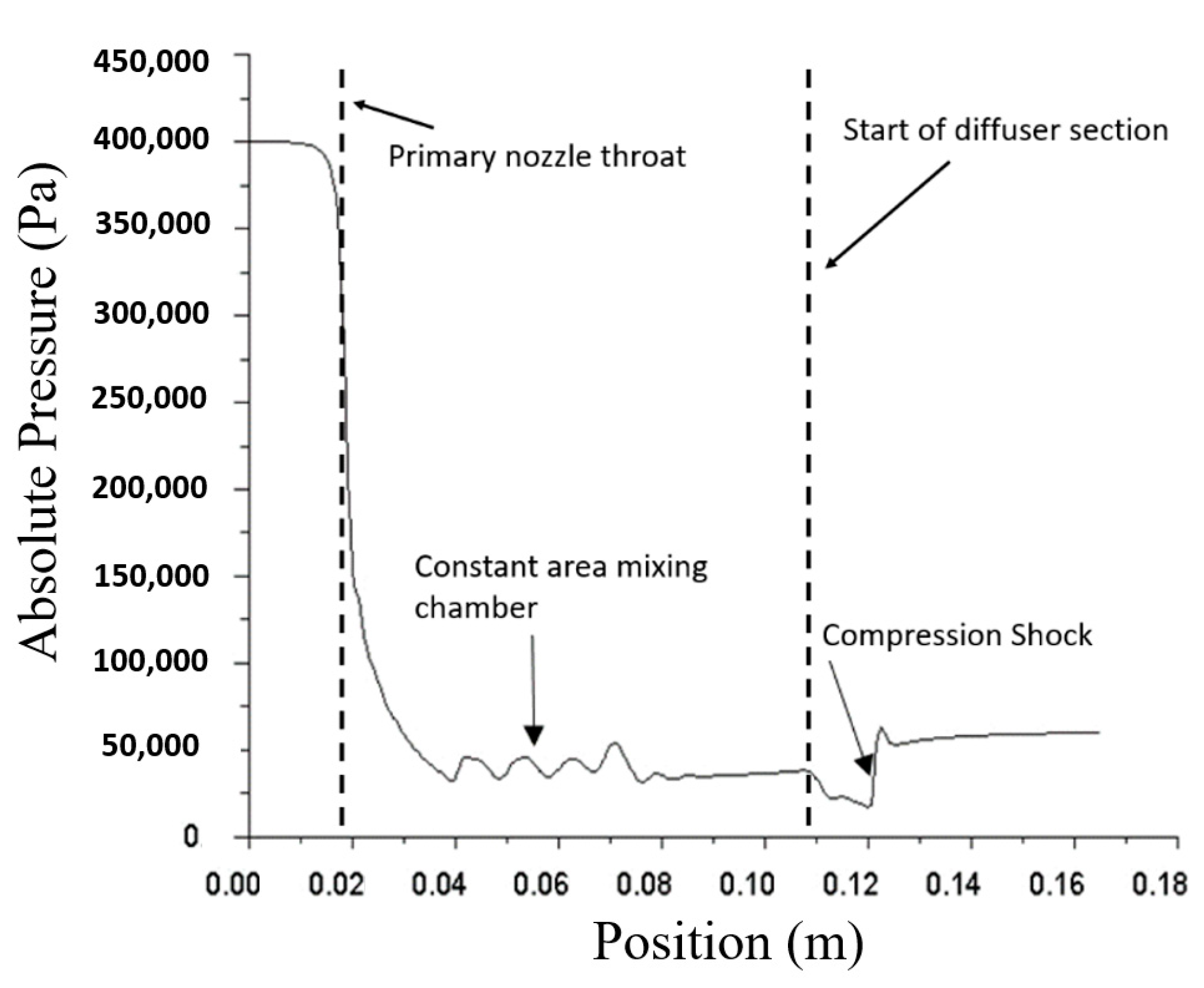
Figure 8 shows the graphical presentation of data extracted from the CFD analysis. It shows the pressure variation at the axis of the ejector. At the throat of the nozzle, the motive flow is expanding sharply, and at the compression shock section, the pressure is increasing sharply, almost instantaneously. After the shock, the pressure is gained smoothly in the diffuser section.
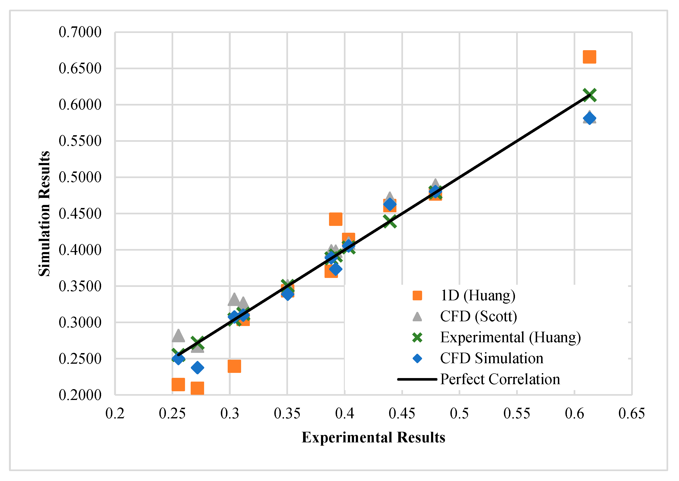
For validation of the CFD model, an ejector design with geometric parameters reported by Huang et al. [34] has been used with the same working fluid and working conditions. For the purpose of validation, Figure 9 gives the comparison of CFD results with various other published works that are using the same geometer and conditions. The solid line is showing the exact match between simulation and experiments, and the points nearer to the line indicate good agreement. For our CFD results, the percentage difference is found to be 3.3%.

3.2. Validation of the Analytical Model

After the validation of the CFD modelling methodology has been established, it can be used to calculate the ejector efficiencies for the analytical model. First of all, the ejector geometry needs to be optimized with CFD analysis so that the optimal value of ejector ER may be obtained. There are many geometric parameters, but Area Ratio (AR) and Nozzle Exit Position (NXP) are two of the most sensitive parameters [26,27,28,29,30,31,32], which can affect the ER by up to 40%. The chocking diameters (nozzle throat and mixing chamber diameter (constant area) control the flow rates [50].
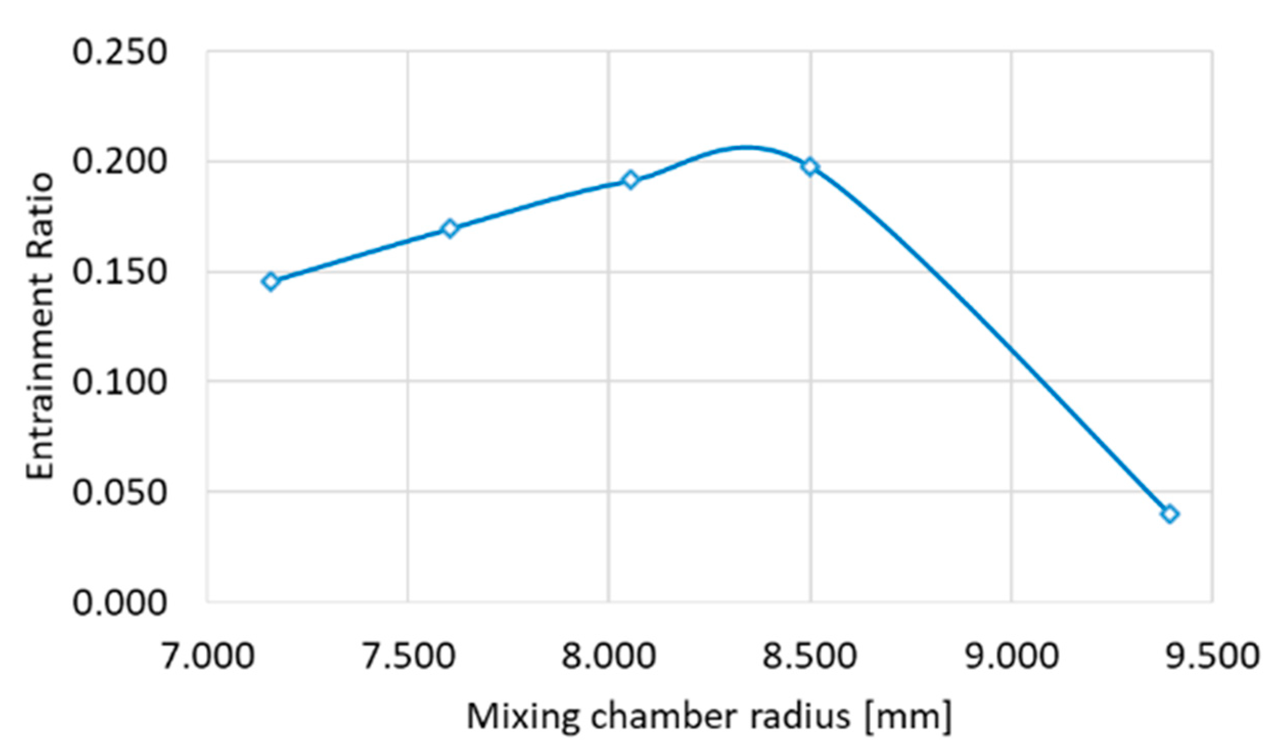
Figure 10 shows the optimization of one parameter, area ration, of the ejector operating with R345fa with motive pressure of 5.5 bar and suction pressure of 0.8 bar and the delivery pressure of 2 bar and the motive flow rate is 0.15 kg/s.
The diagram shows the effect of changing the area ratio (AR) by varying the constant area mixing chamber radius. This way, all the ejector geometric parameters are optimized one by one, and then the same process is repeated until the ejector entrainment ratio can not be increased any further. Hence, CFD design optimization is an iterative process, but it only needs to be done one time so that the data for ejector efficiencies calculations can be extracted.
After optimizing the geometry of the ejector with CFD analysis in FLUENT, the next step is to get similar with the proposed analytical model by adjusting the efficiency values. The enthalpy, entropy and all thermodynamic values at all the sections of the ejector are available for optimized ejector geometry. By using the thermodynamic relations for ejector efficiencies, the values are calculated, which are 0.955, 0.865 and 0.875 for the nozzle, mixing and diffuser efficiencies, respectively. Figure 11 shows a comparison of results for analytical and CFD models, which shows a difference of 2%.
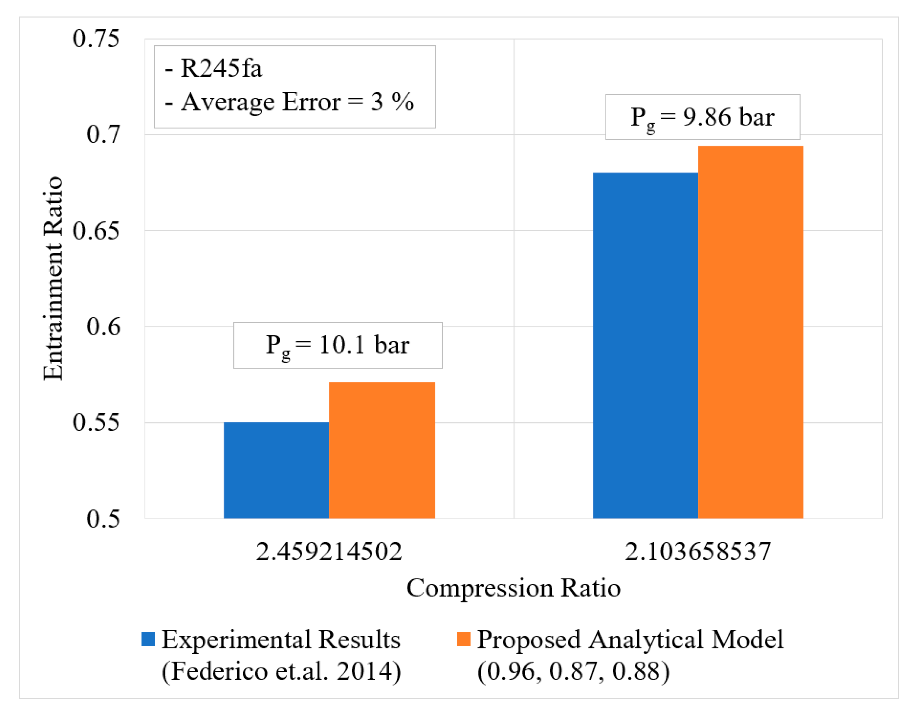
Once the ejector efficiencies have been calculated and integrated into the analytical model, the next step is to validate the analytical model against the published data. Figure 12 below gives the comparison of results, and a good agreement is observed against the experiment data by Federico et al. [41]. The percentage mean difference is 3%.
The model has been validated against the data of Zheng et al. [24]. As seen in Figure 13, an agreement with a difference of 5.65% is obtained.

3.3. Ejector Performance Curves

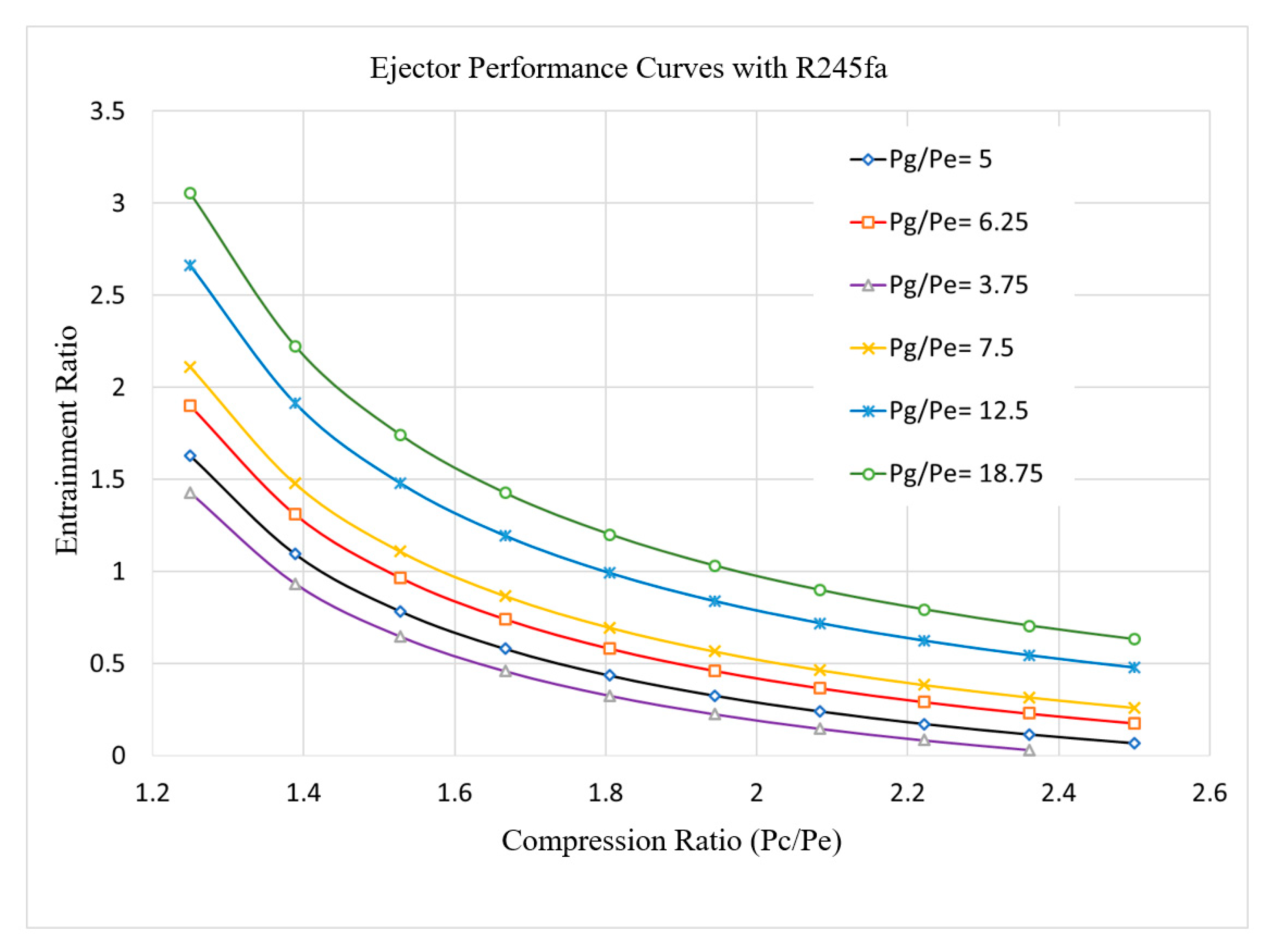
After validating the proposed analytical model, the ejector performance curves with R245fa are presented. These curves can be used for a quick and convenient estimation of ejector ER values for the desired operating conditions.
The performance curves produced by the proposed model are given in Figure 14. The ER of the ejector increases sharply for a lower range of compression ratio (CR) values. For high CR values, the difference of performance is less, even for a significant difference in expansion ratio (generator pressure divided by evaporator pressure). This graph can be used to quickly retrieve the entrainment ratio value for the available working conditions. Similar kinds of graphs are provided by commercial companies working with steam ejectors. Using the same methodology, the proposed model can be used to generate performance curves for various working fluids used in ejector applications.

3.4. Thermal Systems Performances

3.4.1. Ejector Refrigeration System (ERS)

The proposed model has been employed to produce the results reported by Eames et al. [32], and the results have been compared. Table 2 provides the values of simulation results and percentage differences for the specified working conditions.
These values of experimental results have been extracted for the ejector when it is operating at optimum performance. For a fixed motive temperature (and pressure) of the working fluid (R245fa) of 110 °C, and with decreasing the suction temperature (and pressure), the optimum delivery pressures are changing, and the optimum experimental ER values change from 0.94 to 0.69. The ER values given by our proposed model for the same working conditions vary from 0.896 to 0.719, and the average difference is 3.8%. Similarly, the experimental values of COP values of the ERS are changing, and the average difference in the reported experimental results and our simulation results is 4.1%.

3.4.2. Combined Cooling and Power (CCP) System

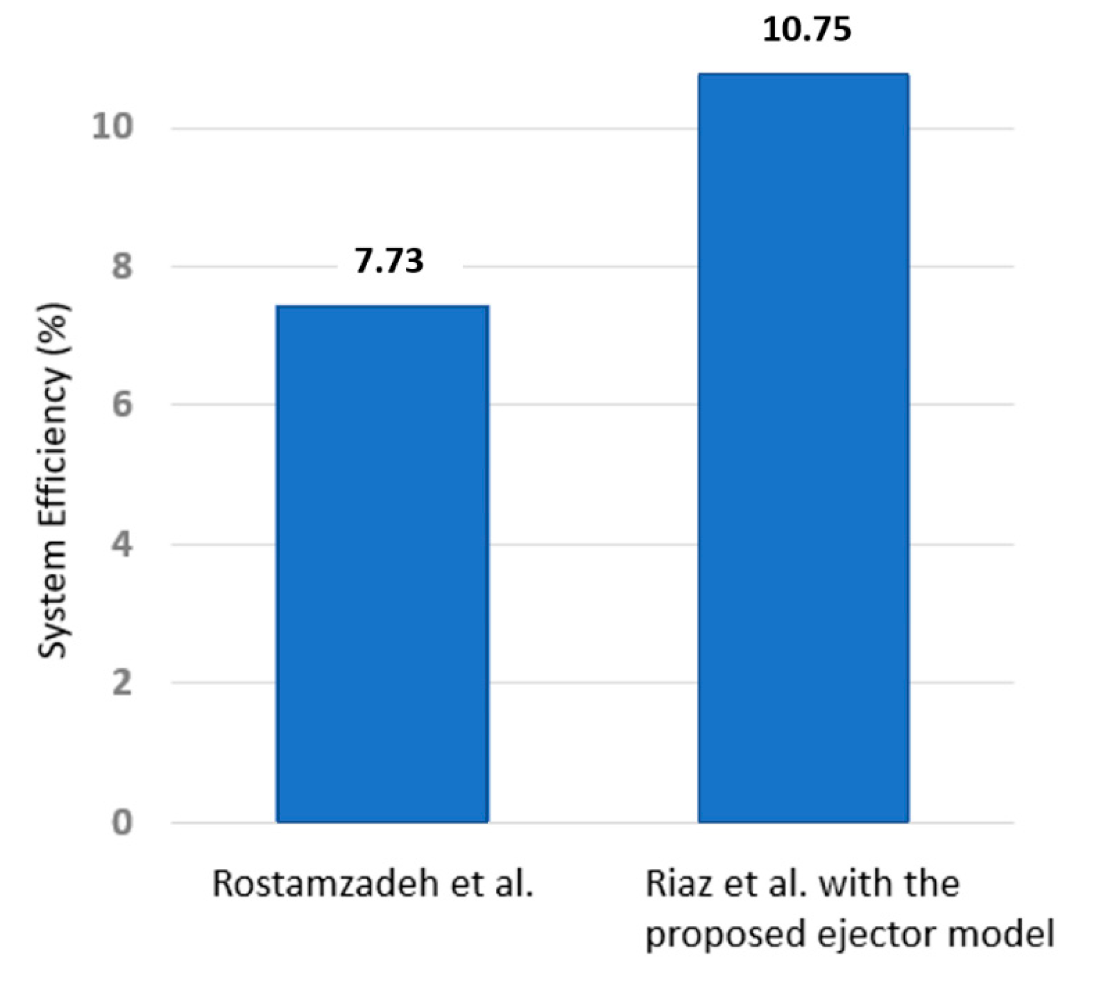
One of the main advantages of the proposed system is that it can easily be incorporated with the overall thermal systems’ models. For optimizing any thermal system, many simulations are required to be run to get the optimum operational point; therefore, it becomes very tedious if the ejector model is not integrated with the system model. A combined cooling and power system that uses ejectors is a relatively complex system, and it becomes very important to run the whole system simulations in an integrated manner. Zheng et al. [24], Chen et al. [22], Rostamzadeh et al. [51] and Riaz et al. [52] are a few of the researchers who have been studying the ejector enhanced CCP systems. The system efficiencies have been calculated by dividing the output with the heat input. The output includes both the electrical power and the cooling, while the cooling produced has been converted into equivalent electrical power. Figure 15 shows the comparison of CCP systems performances. The better performance (10.75% system efficiency) is obtained when the system is optimized by using the proposed ejector model. Without the direct simulation of the complex CCP system, it is not possible to optimize the system by running thousands of system operation points.

4. Conclusions

In this paper, a novel analytical model for ejector simulations has been presented. It is an on-design, optimal performance prediction model, which can directly calculate the ER without employing any iterative process. The detailed thermodynamic modelling is presented along with the single-step computation process, which has been implemented in EES. The pressure of the mixing chamber has been calculated by assuming choked flow conditions for the flow at the converging part of the mixing chamber. This model uses CFD analysis to calculate the three ejector efficiencies, which gives a systematic approach rather than the conventional hit and trial method. The CFD model developed in ANSYS-FLUENT has been validated with experimental data with a percentage difference (maximum) of 3.3%. The ejector efficiencies: nozzle efficiency (ηn), mixing efficiency (ηm) and diffuser efficiency (ηd) are calculated by extracting data from the validated CFD results for optimized ejector geometry. These ejector efficiencies are fed to the analytical model, and the model has been validated against published data, and a good agreement has been seen with an average percentage difference of 4%. The presented model has been used to get the ejector performance curves with R245fa as working fluid. The model has also been directly integrated with thermal systems of ERS and CCP for their simulations, which is possible due to the direct and one step computation process. For ERS, the average difference with experimental values is 4.1%. A novel CCP system configuration, which has been optimized with the proposed model, gives 44% better performance. Similarly, the presented model may be readily integrated with other system models for their simulation and optimizations.

Author Contributions

Conceptualization, F.R. and F.Z.Y.; methodology, F.R., F.Z.Y. and P.S.L.; supervision, P.S.L.; validation, F.R. and F.Z.Y.; data curation, M.A.Q.; formal analysis, F.R., M.A.Q. and M.W.S.; investigation, F.R. and M.F.; writing—original draft, F.R., F.Z.Y. and M.A.Q.; writing—review and editing, F.R., M.A.Q., M.W.S. and M.F.; visualization, F.R., M.A.Q., M.W.S. and M.F.; project administration, F.R. and P.S.L.; funding acquisition, F.R. and P.S.L.; writing—review and editing, M.L. All authors have read and agreed to the published version of the manuscript.

Funding

This research received no external funding.

Institutional Review Board Statement

Not applicable.

Informed Consent Statement

Not applicable.

Conflicts of Interest

The authors declare no conflict of interest.

Nomenclature

0 DZero-dimensional
1 DOne-dimensional
2 DTwo-dimensional
CCPCombined Cooling and Power
CFDComputational fluid dynamics
COPCo-efficient of Performance
DDiameter, mm
EESEngineering Equation Solver
EREntrainment Ratio
ERSEjector Refrigeration System
EVCCEnhanced Vapour Compression Cycle
HVACHeating, ventilation and air conditioning
hEnthalpy, kJ/kg
kIsentropic exponent
mMass flow rate, kg/s
NXPNozzle exit position, mm
ORCOrganic Rankine Cycle
PPressure, bar
TTemperature, °C
VVelocity, m/s
ηEfficiency
Subscripts
1Motive (primary) fluid inlet section
2Entrance of the mixing chamber
3Section where the primary and secondary fluids are fully mixed
4Location of section just before the shock wave
5Location of section just after the shock wave
6Secondary (suction) fluid inlet
7Diffuser outlet
cCondenser (or delivery)
dDiffuser
eEvaporator (suction / secondary)
gGenerator (motive / primary)
idIdeal
isIsentropic
mMixing-chamber
mcmixing chamber (constant-area)
nNozzle (supersonic, converging-diverging)
pPrimary or motive fluid
sSecondary or suction fluid
tThroat, primary nozzle

Appendix A

Appendix A.1. 1-D Model by Huang et al.
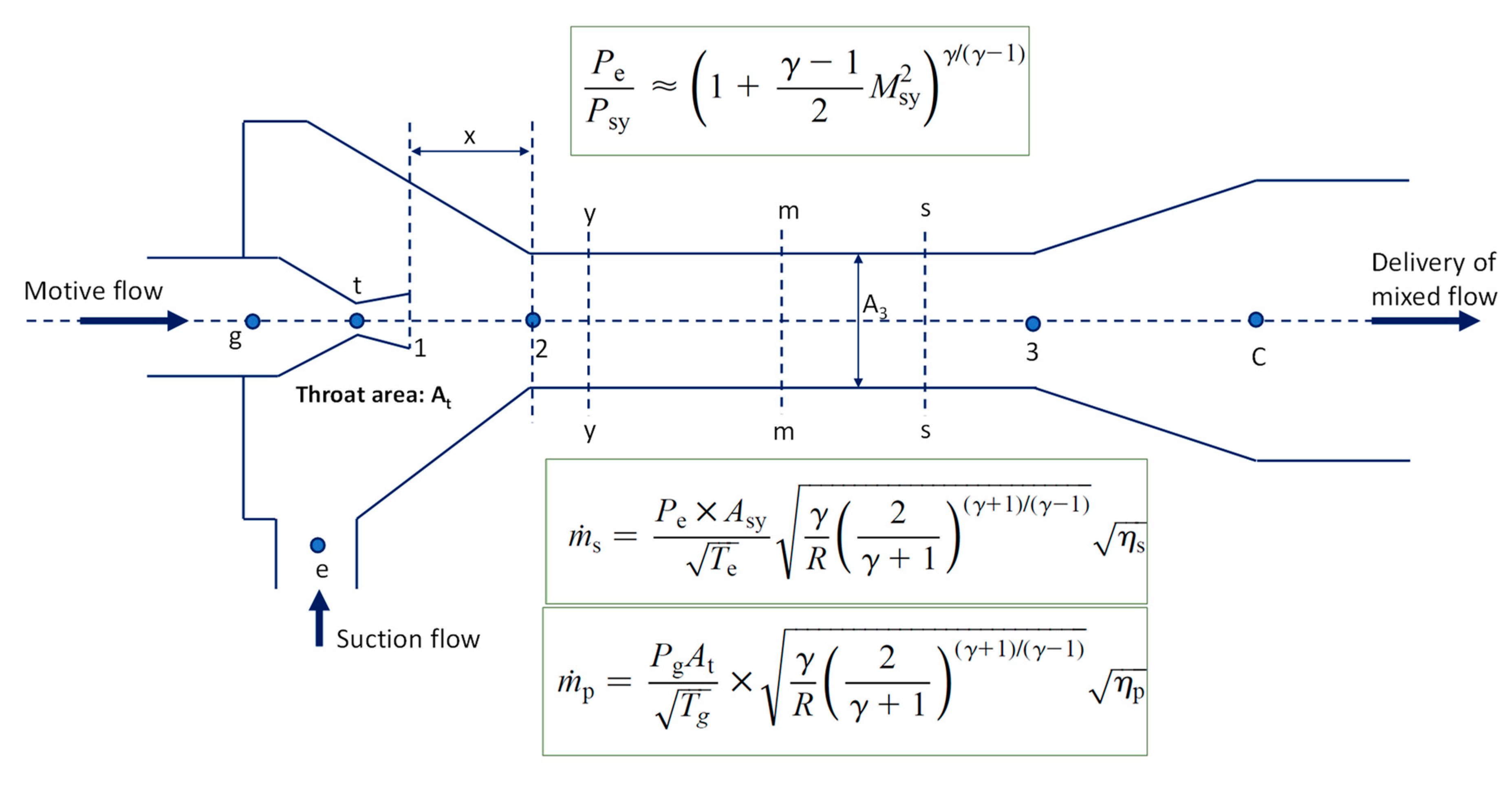
The work of Huang et al. [34] has been referred to by many researchers. They presented a 1-D model, which they validated with their experimental work. Because it is a 1-D model, it needs to calculate all the diameters and hence the area ratio. This model can be used to predict the performance of an ejector of a given geometry; therefore, the performance obtained with this model is not optimum performance for the available working conditions.
Figure A1 shows the geometric design of the ejector along with the notations used in their paper. The main assumption in the model is that the secondary flow is chocked at section y-y. This allows the calculation of secondary fluid pressure at section y-y (Psy), and this pressure is also equal to the primary fluid pressure at the same section y-y. This allows the calculation of the primary and secondary fluid areas at section y-y (because the A3 area value is initially assumed); therefore, the secondary mass flow rate can be calculated. At the end of the calculation, the delivery pressure is checked against the required condenser (delivery) pressure, and if the pressure values are not matching, a new value of A3 is assumed, and the calculation is repeated. Therefore, the model is an iterative model, as shown in Figure A2.
Figure A1. Notations of ejector used in the 1-D model of Huang et al. [34].
Energies 14 02819 g0a1
Figure A2. Computation procedure of the 1-D model presented by Huang et al. [34].
Energies 14 02819 g0a2
To use this 1-D model presented by Huang et al. [34] for various working conditions, an EES model has been developed. Table A1 shows the results of the developed EES model, and Table A2 shows the validation of the developed EES code based on the results reported by Huang et al. [34] for the model EH. R141b has been used as a working fluid. As shown, against the experimental result for entertainment ratio value of 0.4377, Huang et al. [34] reported the simulation result of 0.4627, while the EES model gives 0.4682 (denoted by ER). The percentage difference of 1.2% indicates that the 1-D model has been correctly modelled in EES.
Table A1. Results from the developed EES model based on the 1-D model of Huang et al. [34].
VariableValueUnitsVariableValueUnitsVariableValueUnits
A30.00006642m2Ap10.0000159m2Apy0.00002564m2
Apyi0.00002914m2AR10.64-Asy0.00004078m2
At0.000006243m2cpg939.3J/kg-Kcvg807.2J/kg-K
Dp10.0045mDt0.00282mEffp0.95-
Effs0.85-ER0.4682-Fim0.8-
Fip0.88-Kg1.164-M30.6595-
Mm1.562-Mp12.23-Mpy2.673-
mp0.01069kg/sms0.005006kg/sP358,291Pa
Pc74,748PaPe40,000PaPg604,000Pa
Pm22,866PaPp153,329PaPpy22,866Pa
Psy22,866PaRg132.1J/kg-KTe281.2K
Tg368.1KTm283.7KTpy232.3K
Tsy259.9KVm326.2m/sVpy505m/s
Vsy199.8m/s------
Table A2. Validation of the developed EES model based on the 1-D model of Huang et al. [34].
Pg (Mpa)Tc (°C)A3/Atω
TheoryExperimentDifference (%)TheoryExperimentDifference (%)
0.60431.310.8710.64 (EH)2.10.46270.43775.7

Appendix A.2. 0-D Model by Chen

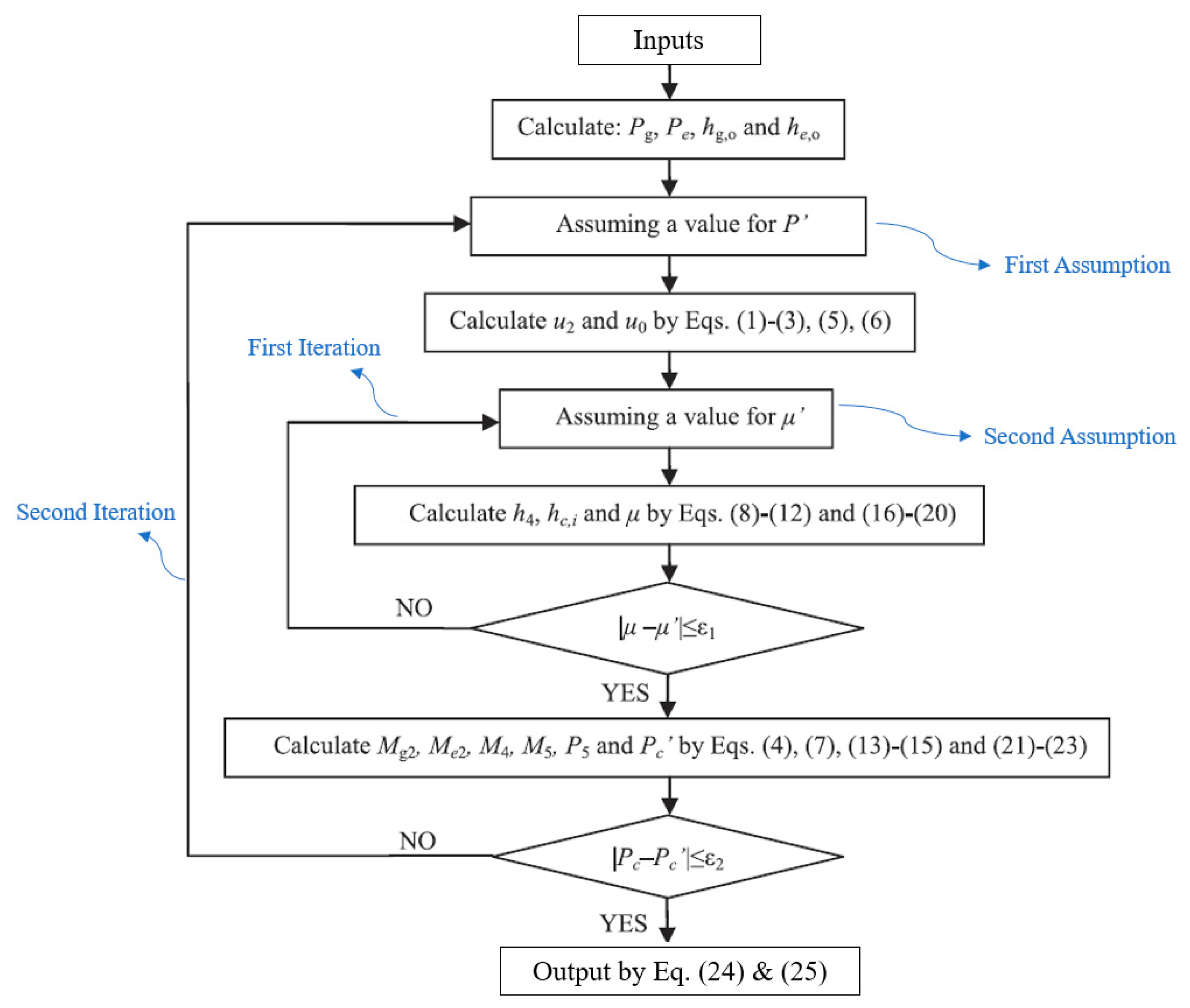
Chen [40] proposed a 0-D model that calculated the optimum performance of the ejector for given operating conditions. This model uses a combination of ideal gas equations and real working fluid properties. This model is a double-iteration model. First, the model assumes a value of pressure in the constant area section (P) it corrects later in a loop against the condenser (delivery) pressure, and then it assumes a value of entrainment ratio (µ) that it corrects later with a calculated value (µ), as shown in Figure A3. Because of the double iterative process, the programming is more challenging, and the model is difficult to integrate with other models.
Figure A3. Computation procedure used by Chen [40] for their 0-D model.
Energies 14 02819 g0a3
The developed model is used to run the same EH model from the experiments of Huang et al. [34], and the results are compared with results reported by Chen [40]. Table A3 shows the comparison of the results. As shown, against the experimental result for entrainment ratio value of 0.4377, Chen [40] reported the simulation result of 0.4387, while the 0-D EES model gives 0.4122. The percentage difference of 6% indicates a good agreement.
Table A3. Comparison of the results of developed EES model and results reported by Huang et al. [34] and Chen [40].
Pg
[bar]
Tg
[°C]
Pc
[bar]
Pevaporator
[bar]
ER
(Experiment by Huang et al. [34])
ER
(Chen [40])
ER
(Developed EES Model)
6.05 95 0.9860.399 0.4377 (Model EH)0.43870.4122
The results from the developed EES model are shown in Table A4. In this double iteration model, the solution converges when ERa (assumed entrainment ratio) value becomes equal to ERcal (calculated entrainment ratio) as well as when Pccal (calculated condenser pressure) becomes equal to the value of Pc (required condenser pressure). The double iterative process makes it difficult for the solution to cover because for every assumed value of one parameter, the other parameter needs to converge hence making it a lengthy process. The successful EES modelling of the 0-D model proposed by Chen [40] enables the calculation of entrainment ratio for various other working conditions for comparison with other models or for using in system analysis and optimization.
Table A4. Result from the developed EES model based on 0-D model of Chen [40].
VariableValueUnitsVariableValueUnitsVariableValueUnits
AR10.45-C4148.6m/scp867.6J/kg-K
cv763J/kg-KEffd0.82-Effm0.85-
Effn0.95-ERa0.4122-ERcal0.4122-
h2274,432J/kgh2i271,964J/kgh4285,967J/kg
hcideal317,315J/kgho271,858J/kghc324,196J/kg
heo282,632J/kghgo341,329J/kgk1.137-
M41.861-M4c1.884-M4st1.747-
M50.5654-Me21.012-Me2st1.011-
Mg22.593-Mg2st2.218-P222,750Pa
P422,750PaP582,405PaPc98,600Pa
Pccal98,639PaPe39,927PaPg604,929Pa
Pge322,428Pas41073J/kg-Kscideal1073J/kg-K
seo1021J/kg-Ksgo1022J/kg-KTe281.2K
Tg368.2Ku2363m/su4276.5m/s
u4i299.9m/suo146.8m/s---

References

  1. Ying, P.; He, R.; Mao, J.; Zhang, Q.; Reith, H.; Sui, J.; Ren, Z.; Nielsch, K.; Schierning, G. Towards tellurium-free thermoelectric modules for power generation from low-grade heat. Nat. Commun. 2021, 12, 1121. [Google Scholar] [CrossRef] [PubMed]
  2. Wang, D.; Ling, X.; Peng, H.; Liu, L.; Tao, L. Efficiency and optimal performance evaluation of organic Rankine cycle for low grade waste heat power generation. Energy 2013, 50, 343–352. [Google Scholar] [CrossRef]
  3. Hamzaoui, M.; Nesreddine, H.; Aidoun, Z.; Balistrou, M. Experimental study of a low grade heat driven ejector cooling system using the working fluid R245fa. Int. J. Refrig. 2018, 86, 388–400. [Google Scholar] [CrossRef]
  4. Zare, V.; Palideh, V. Employing thermoelectric generator for power generation enhancement in a Kalina cycle driven by low-grade geothermal energy. Appl. Therm. Eng. 2018, 130, 418–428. [Google Scholar] [CrossRef]
  5. Lawal, D.U.; Qasem, N.A. Humidification-dehumidification desalination systems driven by thermal-based renewable and low-grade energy sources: A critical review. Renew. Sustain. Energy Rev. 2020, 125, 109817. [Google Scholar] [CrossRef]
  6. Ashraf, W.M.; Uddin, G.M.; Kamal, A.H.; Khan, M.H.; Khan, A.; Ahmad, H.A.; Ahmed, F.; Hafeez, N.; Sami, R.M.Z.; Arafat, S.M.; et al. Optimization of a 660 MWe Supercritical Power Plant Performance—A Case of Industry 4.0 in the Data-Driven Operational Management. Part 2. Power Generation. Energies 2020, 13, 5619. [Google Scholar] [CrossRef]
  7. Riaz, F.; Lee, P.S.; Chou, S.K. Thermal modelling and optimization of low-grade waste heat driven ejector refrigeration system incorporating a direct ejector model. Appl. Therm. Eng. 2020, 167, 114710. [Google Scholar] [CrossRef]
  8. Eicker, U. Low Energy Cooling for Sustainable Buildings; John Wiley & Sons, Ltd.: Hoboken, NJ, USA, 2009. [Google Scholar]
  9. Mao, N.; Pan, D.; Li, Z.; Xu, Y.; Song, M.; Deng, S. A numerical study on influences of building envelope heat gain on operating performances of a bed-based task/ambient air conditioning (TAC) system in energy saving and thermal comfort. Appl. Energy 2017, 192, 213–221. [Google Scholar] [CrossRef]
  10. Awan, M.R.; Riaz, F.; Nabi, Z. Analysis of conditions favourable for small vertical axis wind turbines between building passages in urban areas of Sweden. Int. J. Sustain. Energy 2015, 36, 450–461. [Google Scholar] [CrossRef]
  11. Global Demand for Air-Conditioning to Triple by 2050: Report, Business News & Top Stories—The Straits Times. Available online: https://www.straitstimes.com/business/global-demand-for-air-conditioning-to-triple-by-2050-report (accessed on 6 December 2018).
  12. Riaz, F.; Lee, P.S.; Chou, S.K.; Ranjan, R.; Tay, C.S.; Soe, T. Analysis of Low-Grade Waste Heat Driven Systems for Cooling and Power for Tropical Climate. Energy Procedia 2017, 143, 389–395. [Google Scholar] [CrossRef]
  13. Riaz, F.; Tan, K.H.; Farooq, M.; Imran, M.; Lee, P.S. Energy Analysis of a Novel Ejector-Compressor Cooling Cycle Driven by Electricity and Heat (Waste Heat or Solar Energy). Sustainability 2020, 12, 8178. [Google Scholar] [CrossRef]
  14. Kanoğlu, M.; Çarpınlıoğlu, M.Ö.; Yıldırım, M. Energy and exergy analyses of an experimental open-cycle desiccant cooling system. Appl. Therm. Eng. 2004, 24, 919–932. [Google Scholar] [CrossRef]
  15. Wang, Y.; Chen, T.; Liang, Y.; Sun, H.; Zhu, Y. A novel cooling and power cycle based on the absorption power cycle and booster-assisted ejector refrigeration cycle driven by a low-grade heat source: Energy, exergy and exergoeconomic analysis. Energy Convers. Manag. 2020, 204, 112321. [Google Scholar] [CrossRef]
  16. Pridasawas, W.; Lundqvist, P. An exergy analysis of a solar-driven ejector refrigeration system. Sol. Energy 2004, 76, 369–379. [Google Scholar] [CrossRef]
  17. Chen, J.; Jarall, S.; Havtun, H.; Palm, B. A review on versatile ejector applications in refrigeration systems. Renew. Sustain. Energy Rev. 2015, 49, 67–90. [Google Scholar] [CrossRef]
  18. Khennich, M.; Sorin, M.; Galanis, N. Equivalent Temperature-Enthalpy Diagram for the Study of Ejector Refrigeration Systems. Entropy 2014, 16, 2669–2685. [Google Scholar] [CrossRef] [Green Version]
  19. Pridasawas, W. Solar-Driven Refrigeration Systems with Focus on the Ejector Cycle. Ph.D. Thesis, KTH, Stockholm, Sweden, 2006. [Google Scholar]
  20. Chou, S.; Yang, P.; Yap, C. Maximum mass flow ratio due to secondary flow choking in an ejector refrigeration system. Int. J. Refrig. 2001, 24, 486–499. [Google Scholar] [CrossRef]
  21. Li, X.; Zhao, C.; Hu, X. Thermodynamic analysis of Organic Rankine Cycle with Ejector. Energy 2012, 42, 342–349. [Google Scholar] [CrossRef]
  22. Chen, X.; Su, Y.; Omer, S.; Riffat, S. Theoretical investigations on combined power and ejector cooling system powered by low-grade energy source. Int. J. Low Carbon Technol. 2015, 11, 466–475. [Google Scholar] [CrossRef] [Green Version]
  23. Zhang, K.; Chen, X.; Markides, C.N.; Yang, Y.; Shen, S. Evaluation of ejector performance for an organic Rankine cycle combined power and cooling system. Appl. Energy 2016, 184, 404–412. [Google Scholar] [CrossRef] [Green Version]
  24. Zheng, B.; Weng, Y. A combined power and ejector refrigeration cycle for low temperature heat sources. Sol. Energy 2010, 84, 784–791. [Google Scholar] [CrossRef]
  25. Scott, D.; Aidoun, Z.; Bellache, O.; Ouzzane, M. CFD Simulations of a Supersonic Ejector for Use in Refrigeration Applications. Int. Refrig. Air Cond. 2008, 1–8. Available online: https://www.nrcan.gc.ca/sites/www.nrcan.gc.ca/files/canmetenergy/files/pubs/2008-068_e.pdf (accessed on 12 May 2021).
  26. Varga, S.; Oliveira, A.C.; Diaconu, B. Numerical assessment of steam ejector efficiencies using CFD. Int. J. Refrig. 2009, 32, 1203–1211. [Google Scholar] [CrossRef]
  27. Rusly, E.; Aye, L.; Charters, W.; Ooi, A. CFD analysis of ejector in a combined ejector cooling system. Int. J. Refrig. 2005, 28, 1092–1101. [Google Scholar] [CrossRef]
  28. Varga, S.; Oliveira, A.C.; Diaconu, B. Influence of geometrical factors on steam ejector performance—A numerical assessment. Int. J. Refrig. 2009, 32, 1694–1701. [Google Scholar] [CrossRef]
  29. Chen, J.; Havtun, H.; Palm, B. Investigation of ejectors in refrigeration system: Optimum performance evaluation and ejector area ratios perspectives. Appl. Therm. Eng. 2014, 64, 182–191. [Google Scholar] [CrossRef]
  30. Chunnanond, K.; Aphornratana, S. An experimental investigation of a steam ejector refrigerator: The analysis of the pressure profile along the ejector. Appl. Therm. Eng. 2004, 24, 311–322. [Google Scholar] [CrossRef]
  31. Aphornratana, S.; Eames, I.W. A small capacity steam-ejector refrigerator: Experimental investigation of a system using ejector with movable primary nozzle. Int. J. Refrig. 1997, 20, 352–358. [Google Scholar] [CrossRef]
  32. Eames, I.W.; Ablwaifa, A.E.; Petrenko, V. Results of an experimental study of an advanced jet-pump refrigerator operating with R245fa. Appl. Therm. Eng. 2007, 27, 2833–2840. [Google Scholar] [CrossRef]
  33. Keenan, J.H.; Neumann, E.P.; Lustwerk, F. An Investigation of Ejector Design by Analysis and Experiment. J. Appl. Mech. 1950, 17, 299–309. [Google Scholar] [CrossRef]
  34. Huang, B.; Chang, J.; Wang, C.; Petrenko, V. A 1-D analysis of ejector performance. Int. J. Refrig. 1999, 22, 354–364. [Google Scholar] [CrossRef]
  35. Munday, J.T.; Bagster, D.F. A New Ejector Theory Applied to Steam Jet Refrigeration. Ind. Eng. Chem. Process Des. Dev. 1977, 16, 442–449. [Google Scholar] [CrossRef]
  36. Shestopalov, K.; Huang, B.; Petrenko, V.; Volovyk, O. Investigation of an experimental ejector refrigeration machine operating with refrigerant R245fa at design and off-design working conditions. Part 1. Theoretical analysis. Int. J. Refrig. 2015, 55, 201–211. [Google Scholar] [CrossRef]
  37. Bellos, E.; Tzivanidis, C. Optimum design of a solar ejector refrigeration system for various operating scenarios. Energy Convers. Manag. 2017, 154, 11–24. [Google Scholar] [CrossRef]
  38. ENOGIA—The Small Turbine ORC Company. Available online: http://www.enogia.com/ (accessed on 3 July 2018).
  39. EES: Engineering Equation Solver|F-Chart Software: Engineering Software. Available online: http://fchartsoftware.com/ees/ (accessed on 26 April 2021).
  40. Chen, J. Investigation of Vapor Ejectors in Heat Driven Ejector Refrigeration Systems; KTH: Stockholm, Sweden, 2014. [Google Scholar]
  41. Mazzelli, F.; Milazzo, A. Performance analysis of a supersonic ejector cycle working with R245fa. Int. J. Refrig. 2015, 49, 79–92. [Google Scholar] [CrossRef]
  42. Ansys Fluent|Fluid Simulation Software. Available online: https://www.ansys.com/products/fluids/ansys-fluent (accessed on 26 April 2021).
  43. Zhu, Y.; Cai, W.; Wen, C.; Li, Y. Numerical investigation of geometry parameters for design of high performance ejectors. Appl. Therm. Eng. 2009, 29, 898–905. [Google Scholar] [CrossRef]
  44. Bartosiewicz, Y.; Aidoun, Z.; Desevaux, P.; Mercadier, Y. Cfd-experiments integration in the evaluation of six turbulence models for supersonic ejector modeling. In Proceedings of the Integrating CFD and Experiments Conference, Glasgow, UK, 8–9 September 2003. [Google Scholar]
  45. Chandra, V.V.; Ahmed, M. Experimental and computational studies on a steam jet refrigeration system with constant area and variable area ejectors. Energy Convers. Manag. 2014, 79, 377–386. [Google Scholar] [CrossRef]
  46. Ruangtrakoon, N.; Thongtip, T.; Aphornratana, S.; Sriveerakul, T. CFD simulation on the effect of primary nozzle geometries for a steam ejector in refrigeration cycle. Int. J. Therm. Sci. 2013, 63, 133–145. [Google Scholar] [CrossRef]
  47. Mohamed, S.; Shatilla, Y.; Zhang, T. CFD-based design and simulation of hydrocarbon ejector for cooling. Energy 2019, 167, 346–358. [Google Scholar] [CrossRef]
  48. Muhammad, H.A.; Abdullah, H.M.; Rehman, Z.; Lee, B.; Baik, Y.-J.; Cho, J.; Imran, M.; Masud, M.; Saleem, M.; Butt, M.S. Numerical Modeling of Ejector and Development of Improved Methods for the Design of Ejector-Assisted Refrigeration System. Energies 2020, 13, 5835. [Google Scholar] [CrossRef]
  49. Zhu, Y.; Cai, W.; Wen, C.; Li, Y. Shock circle model for ejector performance evaluation. Energy Convers. Manag. 2007, 48, 2533–2541. [Google Scholar] [CrossRef]
  50. Cengel, Y.A.; Boles, M.A. Thermodynamics: An Engineering Approach, 8th ed.; McGraw-Hill Education: New York, NY, USA, 2015; ISBN 9789814595292. [Google Scholar]
  51. Rostamzadeh, H.; Ghaebi, H.; Parikhani, T. Thermodynamic and thermoeconomic analysis of a novel combined cooling and power (CCP) cycle. Appl. Therm. Eng. 2018, 139, 474–487. [Google Scholar] [CrossRef]
  52. Riaz, F.; Farooq, M.; Imran, M.; Lee, P.S.; Chou, S.K. Energy analysis of a new combined cooling and power system for low-temperature heat utilization. In Proceedings of the ASME 2020 14th International Conference on Energy Sustainability, ES 2020, Online, 17–18 July 2020. [Google Scholar]
Figure 1. Variation of velocity and pressure at different section of ejector [40].
Energies 14 02819 g001
Figure 2. Enthalpy–Entropy diagram for ejector’s thermal processes. The blue line presents the secondary fluid; the red line represents the primary fluid; the pink color represents the mixed fluid; the green color represents the constant pressure mixing process.
Energies 14 02819 g002
Figure 3. Conservation of momentum in constant area mixing chamber before shock.
Energies 14 02819 g003
Figure 4. Procedure of computation used in the model.
Energies 14 02819 g004
Figure 5. Structured meshing for AG1 with 9940 elements for axisymmetric modeling.
Energies 14 02819 g005
Figure 6. CFD results and validation: Mach contours with R141b working fluid for model from [25,34].
Energies 14 02819 g006
Figure 7. CFD results for R141b working fluid.
Energies 14 02819 g007
Figure 8. CFD data extraction for pressure at the axis for ejector model.
Energies 14 02819 g008
Figure 9. Validatio of CFD modeling with published data.
Energies 14 02819 g009
Figure 10. Area Ratio optimization for Ejector with ANSYS-FLUENT.
Energies 14 02819 g010
Figure 11. Validation of analytical model with CFD.
Energies 14 02819 g011
Figure 12. Validation of model with published experiment data.
Energies 14 02819 g012
Figure 13. Validation with simulation data from literature.
Energies 14 02819 g013
Figure 14. R245fa-Performance curves for Ejector.
Energies 14 02819 g014
Figure 15. Optimization of a novel CCP using the proposed ejector model and its performance comparison.
Energies 14 02819 g015
Table 1. Summary of CFD model application settings in ANSYS-FLUENT.
MeshingStructured
TurbulenceModel: k-ε realizable
SolverAxisymmetric, Pressure based
EnergyKept ON
CompressibilityConsidered
RefrigerantConstant Cp, Ideal gas
Boundary ConditionsPressure outlet and inlet
InitializationHybrid
Discretization2nd order scheme
Residuals10^−6
Table 2. comparison of Results of the proposed model with the experimental results reported by Eames et al. [32].
TmotiveTsuctionTdeliveryCompression
Ratio
ER Values,
Eames et al.
COP Value of ERS
Eames et al.
COP of ERS
(Proposed Model)
ER Values
(Proposed Model)
Difference in ER ValuesDifference in COP Values
[°C][°C][°C]Pdelivery/Psuction- -[%][%]
1101533.520.940.670.65220.8964.72.7
11012332.2134831460.760.540.560.7782.43.7
1101032.52.3585365850.690.480.510.7194.26.2
Publisher’s Note: MDPI stays neutral with regard to jurisdictional claims in published maps and institutional affiliations.