Article

Improved IMPES Scheme for the Simulation of Incompressible Three-Phase Flows in Subsurface Porous Media

1
School of Mathematics and Statistics, Guizhou University, Guiyang 550025, China
2
School of Mathematical Sciences, Guizhou Normal University, Guiyang 550025, China
3
Computational Transport Phenomena Laboratory, Division of Physical Science and Engineering, King Abdullah University of Science and Technology, Thuwal 23955-6900, Saudi Arabia
*
Authors to whom correspondence should be addressed.
Energies 2021, 14(10), 2757; https://doi.org/10.3390/en14102757
Submission received: 23 March 2021 / Revised: 30 April 2021 / Accepted: 4 May 2021 / Published: 11 May 2021
(This article belongs to the Special Issue Modeling Multiphase Flow and Reactive Transport in Porous Media)

Abstract

:
In this work, an improved IMplicit Pressure and Explicit Saturation (IMPES) scheme is proposed to solve the coupled partial differential equations to simulate the three-phase flows in subsurface porous media. This scheme is the first IMPES algorithm for the three-phase flow problem that is locally mass conservative for all phases. The key technique of this novel scheme relies on a new formulation of the discrete pressure equation. Different from the conventional scheme, the discrete pressure equation in this work is obtained by adding together the discrete conservation equations of all phases, thus ensuring the consistency of the pressure equation with the three saturation equations at the discrete level. This consistency is important, but unfortunately it is not satisfied in the conventional IMPES schemes. In this paper, we address and fix an undesired and well-known consequence of this inconsistency in the conventional IMPES in that the computed saturations are conservative only for two phases in three-phase flows, but not for all three phases. Compared with the standard IMPES scheme, the improved IMPES scheme has the following advantages: firstly, the mass conservation of all the phases is preserved both locally and globally; secondly, it is unbiased toward all phases, i.e., no reference phases need to be chosen; thirdly, the upwind scheme is applied to the saturation of all phases instead of only the referenced phases; fourthly, numerical stability is greatly improved because of phase-wise conservation and unbiased treatment. Numerical experiments are also carried out to demonstrate the strength of the improved IMPES scheme.

1. Introduction

Numerical simulation for subsurface flows has been extensively applied in industry, such as in the management of groundwater energy and waste pollutants, petroleum engineering, and exploitation of geothermal energy [1,2,3,4,5,6,7,8,9,10,11,12,13]. The main numerical methods in the simulation include the Fully Implicit scheme (FI) [14,15,16,17] and the IMplicit EXplicit scheme (IMEX) [18,19,20]. In the FI scheme, all the unknowns can be derived implicitly. Therefore, it is unconditionally stable. However, it is extremely time-consuming to deal with the nonlinear equations at each time step. Different from the FI scheme, the IMEX scheme processes the linear terms implicitly, while the nonlinear terms explicitly. As a result of this, only conditional stability is guaranteed. More specifically, the IMplicit-Pressure and Explicit-Saturation (IMPES) scheme [15,19,21,22,23,24,25,26] is regarded as a kind of IMEX scheme, which is extensively leveraged in the three-phase flow simulation in porous media. In the IMPES scheme, the pressure is derived implicitly, then the Darcy velocity and saturation are explicitly derived. The IMPES scheme provides the solution of high accuracy, with less time cost than the FI scheme. Moreover, the IMPES scheme is easy to implement and has, therefore, gained great popularity.
In this work, a modified IMPES scheme is designed to simulate incompressible three-phase flows in porous media with the discrete methods of cell-centered finite difference and upwind [27]. An advanced discretized formulation is implied to obtain the total pressure by summing up the discretized conservation equation of each phase, which could guarantee the consistency of the pressure equation. Furthermore, the mass conservation of all the phases can be preserved both locally and globally in this scheme.
This work is organized as follows. Section 2 presents an incompressible and immiscible three-phase flow model. Section 3 reviews the standard IMPES scheme. Section 4 describes the presentation of an improved IMPES scheme. Section 5 shows some applications of our new method.

2. Mathematical Model

In this work, we consider the flow of three incompressible and immiscible phases in porous media. This three-phase flow system can be used for the simulations in a number of natural and engineering circumstances, in particular, the petroleum reservoirs consisting of water, oil and gas phases if the density of the gas phase does not substantially change in the system. We note that the gas phase needs to be modeled by a compressible phase by using, for example, an equation of state, if its density varies substantially within the domain. The assumptions of incompressibility and immiscibility are for the convenience of presentation and numerical implementation here, but most of our results can be extended to compressible three-phase flows in a straightforward way. We use the subscripts w , o and g to denote the three phases (naming from water, oil and gas phases). The equations of immiscible and incompressible three-phase flow are described by
ϕ S β t + · u β = q β , x Ω , t > 0 , β = g , o , w ,
u β = k r β μ β k ( p β + ρ β g z ) , x Ω , t > 0 , β = g , o , w ,
S g + S o + S w = 1 , x Ω , t > 0 ,
p c o w = p o p w , x Ω , t > 0 ,
p c g o = p g p o , x Ω , t > 0 ,
Here, ϕ is the porosity, k is the absolute permeability, S β , ρ β , p β , k r β , q β , u β and μ β are the saturation, the density, the pressure, the relative permeability, the injection or production rate, the Darcy velocity and the viscosity of β phase, respectively, while p c i j is the capillary pressure, g is the gravity and z is the depth.
The domain Ω R 2 is bounded. Γ = Ω is the boundary condition of Ω , and Ω = Γ D Γ N , Γ D Γ N = , where Γ D and Γ N indicate Dirichlet and Neumann boundary conditions. The inlet boundary is presented by Γ i n Γ , where Γ i n = { x Ω : u t · n < 0 } , u t = u w + u o + u g is the total Darcy velocity. The following initial and boundary conditions are added to close the system
S β = S β 0 , x Ω , t = 0 , β = w , o , g ,
p β = p β B , x Γ D , t > 0 , β = w , o , g ,
u β · n = u β B , x Γ N , t > 0 , β = w , o , g ,
S β = S β B , x Γ i n , t > 0 , β = w , o , g ,
where n is the unit normal vector.

3. Standard IMPES Scheme

Following the last section, we can use standard IMPES scheme [24] to solve the PDEs. The key point of the scheme is to decouple pressure and saturation, and the first step is to sum up conservation equation of each phase, leading to
· u t = q t ,
where q t = q w + q o + q g is the total injection or production rate and u t = u w + u o + u g is the total Darcy velocity.
With the phase mobility λ β : = k γ β μ β and the flow potential ψ β : = p β + ρ β g z , the Darcy velocity can be written as u β = λ β k ψ β , where β { w , o , g } , and the potential change ψ c α β between phase α and β can be described as
ψ c o w = ψ o ψ w = p c o w + ( ρ o ρ w ) g z : = ψ c o w ( S w , S g ) ,
ψ c g o = ψ g ψ o = p c g o + ( ρ g ρ o ) g z : = ψ c g o ( S w , S g ) .
The total phase mobility λ t = λ w + λ g + λ o and the fractional flow function f β = λ β / λ t are substituted into Equation (2) to obtain the total Darcy velocity,
u t = λ t k ψ o + f w λ t k ψ c o w f g λ t k ψ c g o ,
which can be rearranged to
λ t k ψ o = u t f w λ t k ψ c o w + f g λ t k ψ c g o .
Substituting Equation (13) into Equation (10), we have the pressure equation,
· ( λ t k ψ o + f w λ t k ψ c o w f g λ t k ψ c g o ) = q t ,
which yields,
· ( λ t k ψ o ) = q t + · ( λ g k ψ c g o ) · ( λ w k ψ c o w ) = : R H S p r e s ( S w , S g ) .
In the above relation, we find that if the saturations S w m and S g m are known, the pressure Equation (16) is linear for ψ o . By relating the Darcy velocities of the water and gas phases to the total Darcy velocity, we find
u w = f w u t + ( f g + f o ) λ w k ψ c o w + f w λ g k ψ c g o ,
u g = f g u t ( f w + f o ) λ g k ψ c g o f g λ w k ψ c o w .
By substituting Equations (17) and (18) into (1), the water and gas phases saturation equations can be read as
ϕ S w t = q w · ( f w u t ) · ( ( f g + f o ) λ w k ψ c o w ) · ( f w λ g k ψ c g o ) = : R H S 1 , s a t ( S w , S g ) ,
ϕ S g t = q g · ( f g u t ) + · ( ( f w + f o ) λ g k ψ c g o ) + · ( f g λ w ψ c o w ) = : R H S 2 , s a t ( S w , S g ) ,
where
ψ c o w = ( ψ c o w S w S w + ψ c o w S g S g ) ,
ψ c g o = ( ψ c g o S w S w + ψ c g o S g S g ) .
If the saturations S g m and S w m at time step m are given, we can implicitly solve ψ o m + 1 by the pressure Equation (16), and update the saturations S w m + 1 and S g m + 1 by the saturation Equations (19) and (20). Consequently, the oil phase saturation S o m + 1 can be calculated by 1 S w m + 1 S g m + 1 . The saturation-pressure system can be decoupled by the standard IMPES scheme which is summarized in Algorithm 1 for completeness.
Algorithm 1 Standard IMPES Scheme
1:
Step 1. Given S w m and S g m , calculate u c o w m + 1 and u c g o m + 1 by using
u c o w m + 1 : = λ w ( S w m ) k ψ c o w m ( S w m , S g m ) , u c g o m + 1 : = λ g ( S g m ) k ψ c g o m ( S w m , S g m ) .
2:
Step 2. Given S w m , S g m , u c o w m + 1 and u c g o m + 1 , find u t , o m + 1 and ψ o m + 1 such that
· u t , o m + 1 = q t · u c o w m + 1 · u c g o m + 1 , u t , o m + 1 = λ t k ψ o m + 1 .
3:
Step 3. Given S w m , S g m , u t , o m + 1 and ψ o m + 1 , update saturation of each phase by
ψ S g m + 1 S g m t m + 1 t m = q g · ( f g u t , o m + 1 ( f o ( S w m , S g m ) + f w ( S w m ) ) u c g o m + 1 f g ( S g m ) u c o w m + 1 ) , ψ S w m + 1 S w m t m + 1 t m = q w · ( f w u t , o m + 1 + ( f o ( S w m , S g m ) + f g ( S g m ) ) u c o w m + 1 + f w ( S w m ) u c g o m + 1 ) , S o m + 1 = 1 S w m + 1 S g m + 1 .
The first and second equations in Step 3 of Algorithm 1 are clearly consistent with Equation (1) when β = w , g . However, the third equation may not satisfy Equation (1). Therefore, the standard IMPES scheme is locally mass conservative for the two reference phases provided that the spatial discretization is also locally conservative, but this local conservation is not preserved for the third phase. In next section, we will propose a fully mass conservative IMPES scheme for this incompressible and immiscible three-phase flow system.

4. Improved IMPES Scheme

In this section, we will introduce a modified scheme to improve the consistency of the standard IMPES method. The governing equations for the incompressible and immiscible three-phase model have been expressed in Section 2. The detailed discretization procedure is showed below.
We first define w β : = k ( p β + ρ β g ) and u β : = λ β w β . We use a rectangular mesh for spatial discretization, and the domain Ω = ( 0 , L x ) × ( 0 , L y ) can be divided into M × N cells, partitioned by δ x × δ y , where
δ x : 0 = x 0 < x 1 < < x M = L x , δ y : 0 = y 0 < y 1 < < y N = L y .
We introduce the following standard notation:
x i 1 2 = x i + x i 1 2 , y i 1 2 = y i + y i 1 2 , h i = x i + 1 2 x i 1 2 , h j = y i + 1 2 y i 1 2 , Ω i 1 2 , j 1 2 = ( x i 1 , x i ) × ( y j 1 , y j ) , Ω i 1 2 , j = ( x i 1 , x i ) × ( y j 1 2 , y j + 1 2 ) , Ω i , j 1 2 = ( x i 1 2 , x i + 1 2 ) × ( y j 1 , y j ) .
The cell-centered finite difference method is employed here to discretize pressure gradient p ( x , y ) at cell centers ( x i 1 2 , y i 1 2 ) , and more details can be found in Rui et al. [28], Weiser and Wheeler [29] and Negaral et al. [21]. The gradient of a general scalar quantity p can be approximated by using a central finite difference in each direction:
Δ x p i , j 1 2 = p i + 1 2 , j 1 2 p i 1 2 , j 1 2 x i + 1 2 x i 1 2 ,
Δ y p i 1 2 , j = p i 1 2 , j + 1 2 p i 1 2 , j 1 2 y j + 1 2 y j 1 2 .
We can estimate w β at the middle of edges by
w β , i , j 1 2 x = k i , j 1 2 ¯ ( Δ x p β , i + 1 2 , j 1 2 + ρ β , i , j 1 2 g i , j 1 2 x ) ,
w β , i 1 2 , j y = k i 1 2 , j ¯ ( Δ y p β , i 1 2 , j + 1 2 + ρ β , i 1 2 , j g i 1 2 , j y ) ,
where k i , j 1 2 ¯ is the harmonic average of k i 1 2 , j 1 2 and k i 1 2 , j 1 2 . Here, we only consider the simplified situations, but Starnoni et al. [30] has applied to one- and two-phase flow in porous media for the general circumstances. Subsequently, we will evaluate Darcy velocity by the upwind method, which needs velocity direction information from the last time step. In the very first time step, the direction velocities information is not yet known, and we propose to use of the following formulations:
u β , i , j 1 2 0 , x = λ ¯ β , i , j 1 2 0 w β , i , j 1 2 1 , x , u β , i 1 2 , j 0 , y = λ ¯ β , i 1 2 , j 0 w β , i 1 2 , j 1 , y ,
where
λ ¯ β , i , j 1 2 0 = 1 2 ( λ β ( S w , i 1 2 , j 1 2 0 , S g , i 1 2 , j 1 2 0 ) + λ β ( S w , i + 1 2 , j 1 2 0 , S g , i + 1 2 , j 1 2 0 ) ) ,
λ ¯ β , i 1 2 , j 0 = 1 2 ( λ β ( S w , i 1 2 , j 1 2 0 , S g , i 1 2 , j 1 2 0 ) + λ β ( S w , i 1 2 , j + 1 2 0 , S g , i 1 2 , j + 1 2 0 ) ) .
For all later time steps (i.e., m 1 ), the Darcy velocities are computed by
u β , i , j 1 2 m , x = λ β ( S w , i , j 1 2 m , , x , S g , i , j 1 2 m , , x ) w β , i , j 1 2 m , x , u β , i 1 2 , j m , y = λ β ( S w , i 1 2 , j m , , y , S g , i 1 2 , j m , , y ) w β , i 1 2 , j m , y .
The saturation S β m , for all phases can be discretized by the traditional upwind method
S β , i , j 1 2 m , x = S β , i 1 2 , j 1 2 m , x , u β , i , j 1 2 m 1 , x 0 , S β , i + 1 2 , j 1 2 m , x , elsewise , , S β , i 1 2 , j m , y = S β , i 1 2 , j 1 2 m , y , u β , i 1 2 , j m 1 , y 0 , S β , i 1 2 , j + 1 2 m , y , otherwise . .
With the above pressure and velocity formulations, we can obtain the discretized forms of Equations (1)–(5) at each time step m,
ϕ S β , i 1 2 , j 1 2 m + 1 S β , i 1 2 , j 1 2 m t m + 1 t m + B β , i 1 2 , j 1 2 ( p β m + 1 ) = q β , i 1 2 , j 1 2 , β = g , w , o ,
S g , i 1 2 , j 1 2 m + 1 + S w , i 1 2 , j 1 2 m + 1 + S o , i 1 2 , j 1 2 m + 1 = 1 ,
p o , i 1 2 , j 1 2 m + 1 p w , i 1 2 , j 1 2 m + 1 = p c o w ( S w , i 1 2 , j 1 2 m , S g , i 1 2 , j 1 2 m ) ,
p g , i 1 2 , j 1 2 m + 1 p o , i 1 2 , j 1 2 m + 1 = p c g o ( S g , i 1 2 , j 1 2 m , S w , i 1 2 , j 1 2 m ) ,
where,
B β , i 1 2 , j 1 2 ( p β m + 1 ) = λ β ( S w , i , j 1 2 m , , x , S g , i , j 1 2 m , , x ) w β , i , j 1 2 x , m + 1 λ β ( S w , i 1 , j 1 2 m , , x , S g , i 1 , j 1 2 m , , x ) w β , i 1 , j 1 2 x , m + 1 x i x i 1 + λ β ( S w , i 1 2 , j m , , y , S g , i 1 2 , j m , , y ) w β , i 1 2 , j y , m + 1 λ β ( S w , i 1 2 , j 1 m , , y S g , i 1 2 , j 1 m , , y ) w β , i 1 2 , j 1 y , m + 1 y j y j 1 .
By summing up the above discrete conservation equations of all the three phases, the total conservation equation is presented as
β = g , w , o B β , i 1 2 , j 1 2 ( p β m + 1 ) = β = g , w , o q β , i 1 2 , j 1 2 .
The above equation has three unknown pressures p β m + 1 , β = o , g , w . We need the following two additional equations to implicitly solve p β m + 1 :
p o , i 1 2 , j 1 2 m + 1 p w , i 1 2 , j 1 2 m + 1 = p c o w ( S w , i 1 2 , j 1 2 m , S g , i 1 2 , j 1 2 m ) ,
p g , i 1 2 , j 1 2 m + 1 p o , i 1 2 , j 1 2 m + 1 = p c g o ( S g , i 1 2 , j 1 2 m , S w , i 1 2 , j 1 2 m ) .
We consider p o m + 1 as the primary unknown for pressures, and we can eliminate the other two pressures p g m + 1 and p w m + 1 from the system. To do this, we substitute Equations (35) and (36) into Equation (34) to obtain
β = g , w , o B β , i 1 2 , j 1 2 ( p o m + 1 ) = β = g , w , o q β , i 1 2 , j 1 2 B g , i 1 2 , j 1 2 ( p c g o m + 1 ) + B w , i 1 2 , j 1 2 ( p c o w m + 1 ) .
Finally, the saturation S β m is explicitly updated by using the mass conservation law for each phase. The complete procedure is shown in Algorithm 2. It is clear that the fully conservative IMPES is unbiased toward any of the three phases. We state two methods to update saturation, which is shown in step 3 of Algorithm 2, and the equivalence between these two methods can be proven.
Algorithm 2 Improved IMPES Scheme
1:
Step 1. Find p c o w m + 1 and p c g o m + 1 by p c o w m + 1 = p o m + 1 p w m + 1 and p c g o m + 1 = p g m + 1 p o m + 1 which
2:
are the discretized formulations of the Equations (4) and (5).
3:
Step 2. Find p o m + 1 by solving the Equation (37), then update p g m + 1 and p w m + 1 by
p g m + 1 = p c g o m + 1 + p o m + 1 , p w m + 1 = p o m + 1 p c o w m + 1 .
4:
Step 3. Obtain w β m + 1 from w β m + 1 = k ( p β m + 1 + ρ β m + 1 g ) , and solve the phase saturation S β m + 1 by one of the following two methods,
5:
Method I: Choose β = w , g , then update the saturation S β m + 1 by the Equation (29). The
6:
oil phase saturation S o m + 1 can be given by S o m + 1 = 1 S w m + 1 S g m + 1 .
7:
Method II: Choose β = w , g , o , then update the saturation S β m + 1 by the Equation (29).
Lemma 1.
If S w m + S g m + S o m = 1 , Method I is equivalent to Method II for the improved IMPES scheme.
Proof. 
Firstly, using Method II, we can obtain the following three equations:
ϕ S w , i 1 2 , j 1 2 m + 1 S w , i 1 2 , j 1 2 m t m + 1 t m + B w , i 1 2 , j 1 2 ( p w m + 1 ) = q w , i 1 2 , j 1 2 ,
ϕ S o , i 1 2 , j 1 2 m + 1 S o , i 1 2 , j 1 2 m t m + 1 t m + B o , i 1 2 , j 1 2 ( p o m + 1 ) = q o , i 1 2 , j 1 2 ,
ϕ S g , i 1 2 , j 1 2 m + 1 S g , i 1 2 , j 1 2 m t m + 1 t m + B g , i 1 2 , j 1 2 ( p g m + 1 ) = q g , i 1 2 , j 1 2 .
With the relation (34), we can obtain
ϕ S w , i 1 2 , j 1 2 m + 1 S w , i 1 2 , j 1 2 m t m + 1 t m + ϕ S g , i 1 2 , j 1 2 m + 1 S g , i 1 2 , j 1 2 m t m + 1 t m + ϕ S o , i 1 2 , j 1 2 m + 1 S o , i 1 2 , j 1 2 m t m + 1 t m = 0 .
Combining it with S w m + S g m + S o m = 1 , we deduce
S w m + 1 + S g m + 1 + S o m + 1 = 1 .
Secondly, if Method I is used to this improved IMPES scheme, we have the forms below
ϕ S w , i 1 2 , j 1 2 m + 1 S w , i 1 2 , j 1 2 m t m + 1 t m + B w , i 1 2 , j 1 2 ( p w n + 1 ) = q w , i 1 2 , j 1 2 ,
ϕ S g , i 1 2 , j 1 2 m + 1 S g , i 1 2 , j 1 2 m t m + 1 t m + B g , i 1 2 , j 1 2 ( p g m + 1 ) = q g , i 1 2 , j 1 2 .
Combining Equation (34) with the restriction S w k + S g k + S o k = 1 , k = m , m + 1 , we can quickly find the following desired result
ϕ S o , i 1 2 , j 1 2 m + 1 S o , i 1 2 , j 1 2 m t m + 1 t m + B o , i 1 2 , j 1 2 ( p o m + 1 ) = q g , i 1 2 , j 1 2 .
Thus, Method I and Method II are equivalent. □
The estimated saturation of three phases meets the discretized mass-conservation Equation (29). For T is a finite partition of Ω , and any cell E T , We have the following local conservation of mass for three phases.
Lemma 2.
For any E T , the estimated saturation of three phases solved by the proposed IMPES scheme meets the following local mass-conservation law on E,
E ϕ S β m + 1 S β m t m + 1 t m d x + E λ β ( S β m , ) w β m + 1 · n d σ = E q β d x , β = w , o , g .
Proof. 
Let E T be a element and define T = { E i 1 2 , j 1 2 = ( x i 1 , x i ) × ( y j 1 , y j ) : i = 1 , 2 , , M ; j = 1 , 2 , , N } . We note that the saturation-conservative Equation (1) can be rewritten into,
ϕ S β , t + · ( λ β w β ) = q β , β = w , o , g .
Using the divergence theorem, we have,
E ϕ S β , t d x + E λ β w β · n d σ = E q β d x , β = w , o , g ,
where, n is the outer unit normal vector. When E = E i 1 2 , j 1 2 = ( x i 1 , x i ) × ( y j 1 , y j ) , applying the explicit method for time discretization, the Equation (49) can be rewritten into
E i 1 2 , j 1 2 ϕ S β m + 1 S β m t m + 1 t m d x + E i 1 2 , j 1 2 λ β ( S β m , ) w β m + 1 · n d σ = E i 1 2 , j 1 2 q β d x , β = g , w , o .
Since the rectangular cell E i 1 2 , j 1 2 T has four vertices x i 1 , j , x i , j , x i , j 1 , x i , j . We denote E i 1 2 , j 1 2 by the midpoints of cell edges. We also note that the Equation (50) can be consistent with Equation (29) on E i 1 2 , j 1 2 . Therefore, the improved IMPES scheme is local mass-conservative for three phases. □

5. Numerical Experiments

In this section, four numerical experiments are simulated using our improved IMPES scheme formulated in the previous section. These numerical results demonstrate various features of the proposed scheme. The gravity and capillary pressure are neglected in following three examples for convenience, but the proposed model and numerical scheme in this paper are also applicable to cases with non-zero gravity and capillary pressure. The gravity and capillary pressure effects are considered in example 4, which leads to the counter current flow. The numerical experiment of example 4 is used to verify that the proposed scheme can work well for the situation counter current flow.
Example 1. This example shows a three-phase flow in a homogeneous porous media with a size of 100 × 100 m and a permeability of 100 md. The media are initially saturated with water, oil and gas which have a volume fraction of 10%, 70% and 20% respectively. Water is injected into the porous media at northeast corner of the domain with a constant rate of 6.98 × 10 6 m 3 / s . Water–oil–gas mixture is produced at the southwest corner of the domain, where the pressure is fixed at 1 atm. Figure 1 shows the pressure at different time. Figure 2, Figure 3 and Figure 4 illustrate the saturation of water, oil and gas at different times.
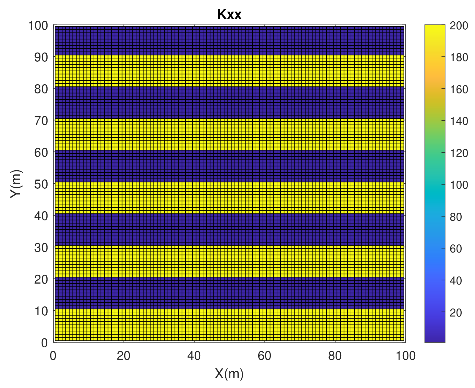
Example 2. This example shows a three-phase flow in layered porous media in a square domain of [ 0 , 100 m ] × [ 0 , 100 m ] and a permeability field is shown in Figure 5. Water is injected at the west edge of the domain with a constant rate, and the mixture is produced at the east edge of the domain where pressure is fixed at 1 atm. Figure 6 shows the pressure at different times. Figure 7, Figure 8 and Figure 9 illustrate the saturation of water, oil and gas at different times.
Example 3. This example shows a three-phase flow in a homogeneous porous media with a square domain of [ 0 , 120 m ] × [ 0 , 120 m ] and a permeability is 120 md. In the simulation of beginning, a block water is located at the center of the domain, there is no oil in the rest of the domain. Water is injected into the porous media at the northeast corner of the domain with a constant rate of 6.98 × 10 6 m 3 / s . Water–oil–gas mixture is produced at the southwest corner of the domain, where the pressure is fixed at 1 atm. Figure 10 shows the pressure field at different time. Figure 11, Figure 12 and Figure 13 illustrate the saturation of water, oil and gas at different time.
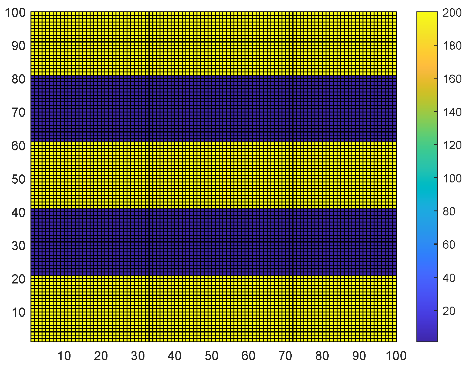
Example 4. This example illustrates a three-phase flow in a heterogeneous porous media with a square domain of [ 0 , 100 m ] × [ 0 , 100 m ] and a permeability distribution is shown in Figure 14. The gravity and capillarity is considered in this example. Water is injected in the central part of west boundary at a constant rate of 1.3952 × 10 4 m 4 / s and the pressure is set as 1 atm on the upper and lower parts of the east boundary where the oil–gas–water mixture is yielded. No flow conditions are enforced on the rest parts of the boundary. The initial distributions of oil, gas, water is shown in Figure 15. Figure 16 shows the Darcy velocity fields of the three phases. Figure 17 illustrates the saturation distributions of water, oil and gas phase after 91,251 days. From the simulation results, we find that the proposed numerical scheme is able to simulate this counter-current flow situation well.
Finally, we calculated the residual (mass conservation error) of saturation equation for each phase at every time step in the simulation by l norm given by formula (51). For the improved IMPES scheme, the calculated mass conservation errors of three phases at all simulation time steps are in the magnitude of 10 16 , which is considered to be zero without the round-off error. We also ran this example with the same conditions using a conventional IMPES scheme and calculated the residual of mass conservation equation of each phase. The calculated errors of two referred phases (water and gas) at all simulation time steps are in the magnitude of 10 16 . However, we also calculated the global error for each phase at all simulation time steps and found that the global error of non-referred phase is accumulating from in magnitude of 10 10 to 10 4 .
e r r β , m = max 1 x n x 1 , 1 j n y 1 | ϕ i 1 2 , j 1 2 S i 1 2 , j 1 2 β , m S i 1 2 , j 1 2 β , m 1 t m t m 1 + B β , i 1 2 , j 1 2 q β , i 1 2 , j 1 2 | .

6. Conclusions

In this work, we have proposed an improved IMPES to simulate three-phase flow systems. Conventional IMPES schemes discretize the pressure equation and two (out of three) saturation equations independently. While this independence could allow one to choose a separate desired numerical algorithm for each of the pressure and saturation equations, the discretized pressure equation is unfortunately inconsistent with the discretized saturation equations. To address this issue, we proposed an improved IMPES scheme, where the discretized pressure equation is fully consistent with the discretized saturation equations. Specifically, the discrete pressure equation in our algorithm is not obtained by discretizing the continuum pressure equation as most people did in the literature; instead, it is obtained by summing up the discretized formulations of the conservation equations for all phases.
Even though the decoupling of the pressure and saturation is majorly based on conventional IMPES schemes, the consistency in our decoupling yields a number of desired numerical features. The most significant improvement in the numerical behavior is the mass conservative property honored in each of the three phases both locally and globally. Conventional IMPES usually solves only two saturation equations numerically (which we refer to as two reference phases), but not the third saturation equation; thus it has a built-in bias, which is eliminated in our improved IMPES scheme. In particular, the conventional IMPES upwinds only the two reference phases, but our scheme is able to apply the upwind scheme to all three phases.
We used the common cell-centered finite difference method for spatial discretization in our numerical examples, but other locally conservative spatial discretizations can also be used in our improved IMPES. Four numerical cases have been carried out to demonstrate the strengths of the improved IMPES scheme. Various flow patterns and a number of different boundary conditions were numerically studied. We also repeated the same numerical examples using conventional IMPES (not shown in this paper for brevity) and enhanced numerical stability has been observed in our scheme as compared to the conventional one. In numerical example 4, we also considered the effects of capillary and gravity for three-phase flow in heterogeneous porous media. Since the gravity segregation among three phases, the counter-current flow is appeared in vertical orientation of the reservoir. We did not consider the compressibility and miscibility of gas for three-phase flow in this study, which is to consider compressible and partially miscible three phases as our near future work.

Author Contributions

Conceptualization, R.L. and S.S; investigation, R.L., X.F. and X.L.; methodology, R.L., X.F., X.L and S.S.; writing—original draft preparation, R.L. and X.Z.; funding acquisition, X.F., X.L. and S.S.; software, R.L. and X.F.; visualization, X.F.; writing—reviewing and editing, X.L. and S.S.; supervision, X.L. and S.S.; projection administration, X.L. and S.S. All authors have read and agreed to the published version of the manuscript.

Funding

The first and third authors are supported by the NSF of China (No.11961008, 11461013). The second author is supported by the NSF of China (No. 12061024, 51874262), Program for Sci-tech Talents of Provincial Education Department of Guizhou Province of China (No. KY[2021]304) and the Doctoral Scientific Research Foundation of Guizhou Normal University (No. GZNUD[2019]17). The fourth and fifth authors are supported by King Abdullah University of Science and Technology (KAUST) through the grants BAS/1/1351-01, URF/1/4074-01 and URF/1/3769-01, and the NSF of China (No. 51874262, 51936001).

Data Availability Statement

Not applicable.

Acknowledgments

Our deepest gratitude goes to the anonymous reviewers for their careful work and thoughtful suggestions that have helped improve this paper substantially.

Conflicts of Interest

The authors declare no conflict of interest.

References

  1. Chen, H.; Kou, J.; Sun, S.; Zhang, T. Fully mass-conservative IMPES schemes for incompressible two-phase flow in porous media. Comput. Methods Appl. Mech. Eng. 2019, 350, 641–663. [Google Scholar] [CrossRef]
  2. Chen, H.; Sun, S. A new physics-preserving IMPES scheme for incompressible and immiscible two-phase flow in heterogeneous porous media. J. Comput. Appl. Math. 2021, 381, 113035. [Google Scholar] [CrossRef]
  3. Redondo, C.; Rubio, G.; Valero, E. On the efficiency of the IMPES method for two phase flow problems in porous media. J. Pet. Sci. Eng. 2018, 164, 427–436. [Google Scholar]
  4. Hoteit, H.; Firoozabadi, A. Numerical modeling of two-phase flow in heterogeneous permeable media with different capillarity pressures. Adv. Water Resour. 2008, 31, 56–73. [Google Scholar] [CrossRef]
  5. Hoteit, H.; Firoozabadi, A. An efficient numerical model for incompressible two phase flow in fracture media. Adv. Water Resour. 2008, 31, 891–905. [Google Scholar] [CrossRef]
  6. Lux, J.; Anguy, Y. A study of the behavior of implicit pressure explicit saturation (IMPES) schedules for two-phase flow in dynamic pore network models. Transp. Porous Media 2012, 93, 203–221. [Google Scholar] [CrossRef]
  7. Chen, Z.; Ewing, R.E. Comparison of various formulations of three-phase flow in porous media. J. Comput. Phys. 1997, 132, 362–373. [Google Scholar] [CrossRef] [Green Version]
  8. Douglas, J., Jr. Finite difference methods for two-phase incompressible flow in porous media. SIAM J. Numer. Anal. 1983, 20, 681–696. [Google Scholar] [CrossRef]
  9. Rahman, N.A.; Lewis, R.W. Finite element modelling of multiphase immiscible flow in deforming porous media for subsurface systems. Comput. Geotech. 1999, 24, 41–63. [Google Scholar] [CrossRef]
  10. Allen, M.B., III. Numerical modelling of multiphase flow in porous media. Adv. Water Resour. 1985, 8, 162–187. [Google Scholar] [CrossRef] [Green Version]
  11. Yang, H.; Li, Y.; Sun, S. Nonlinearly preconditioned constraint-preserving algorithms for subsurface three-phase flow with capillarity. Comput. Methods Appl. Mech. Eng. 2020, 367, 113140. [Google Scholar] [CrossRef]
  12. Abreu, E.; Furtado, F.; Pereira, F. On the numerical simulation of three-phase reservoir transport problems. Transp. Theory Stat. Phys. 2004, 33, 503–526. [Google Scholar] [CrossRef]
  13. Stone, H.L. Probability model for estimating three-phase relative permeability. J. Pet. Technol. 1970, 22, 214–218. [Google Scholar] [CrossRef]
  14. Monteagudo, J.E.P.; Firoozabadi, A. Comparison of fully implicit and IMPES formulations for simulation of water injection in fractured and unfractured media. Int. J. Numer. Methods Eng. 2010, 69, 698–728. [Google Scholar] [CrossRef]
  15. Aziz, K.; Settari, A. Petroleum Reservoir Simulation, 3rd ed.; Applied Science Publishers: London, UK, 1979; pp. 135–139. [Google Scholar]
  16. Yang, H.; Sun, S.; Li, Y.; Yang, C. A fully implicit constraint-preserving simulator for the black oil model of petroleum reservoirs. J. Comput. Phys. 2019, 396, 347–363. [Google Scholar] [CrossRef]
  17. Gao, Y.; Mei, L. Implicit-explicit multistep methods for general two-dimensional nonlinear Schrödinger equations. Appl. Numer. Math. 2016, 109, 41–60. [Google Scholar] [CrossRef]
  18. Ascher, U.M.; Ruuth, S.J.; Wetton, B.T.R. Implicit-explicit methods for time-dependent partial differential equations. SIAM J. Numer. Anal. 1995, 32, 797–823. [Google Scholar] [CrossRef]
  19. Kou, J.; Sun, S. On iterative IMPES formulation for two-phase flow with capillarity in heterogeneous porous media. Int. J. Numer. Anal. Model. Ser. 2010, 1, 20–40. [Google Scholar]
  20. Ruuth, S.J. Implicit-explicit methods for reaction-diffusion problems in pattern formation. J. Math. Biol. 1995, 34, 148–176. [Google Scholar] [CrossRef]
  21. Negara, A.; El-amin, M.F.; Sun, S. Simulation of CO2 plume in porous media: Consideration of capillary and buoyancy effects. Int. J. Numer. Anal. Model. 2011, 2, 315–337. [Google Scholar]
  22. Fan, X.; Salama, A.; Sun, S. A locally and globally phase-wise mass conservative numerical algorithm for the two-phase immiscible flow problems in porous media. Comput. Geotech. 2020, 119, 103370. [Google Scholar] [CrossRef]
  23. Chen, Z.; Huan, G.; Li, B. An improved IMPES method for two-phase flow in porous media. Transp. Porous Media 2004, 54, 361–376. [Google Scholar] [CrossRef]
  24. Jo, J.; Kwak, D.Y. An IMPES scheme for a two-phase flow in heterogeneous porous media using a structured grid. Comput. Methods Appl. Mech. Eng. 2017, 317, 684–701. [Google Scholar] [CrossRef] [Green Version]
  25. Kou, J.; Sun, S. A new treatment of capillarity to improve the stability of IMPES two-phase flow formulation. Comput. Fluids 2010, 39, 1923–1931. [Google Scholar] [CrossRef]
  26. Sheldon, J.W.; Zondek, B.; Cardwell, W.T. One-dimensional, incompressible, noncapillary, two-phase fluid flow in a porous medium. Trans. AIME 1959, 207, 136–143. [Google Scholar] [CrossRef]
  27. Kou, J.; Sun, S. Upwind discontinuous Galerkin methods with conservation of mass of both phases for incompressible two-phase flow in porous media. Numer. Methods Partial. Differ. Equ. 2014, 30, 1674–1699. [Google Scholar] [CrossRef]
  28. Rui, H.; Pan, H. A block-centered finite difference method for the Darcy–Forchheimer model. SIAM J. Numer. Anal. 2012, 50, 2612–2631. [Google Scholar] [CrossRef]
  29. Weiser, A.; Wheeler, M.F. On convergence of block-centered fnite differences for elliptic problems. SIAM J. Numer. Anal. 1988, 25, 351–375. [Google Scholar] [CrossRef]
  30. Starnoni, M.; Berre, I.; Keilegavlen, E.; Nordbotten, J.M. Consistent MPFA discretization for flow in the presence of gravity. Water Resour. Res. 2019, 55, 10105–10118. [Google Scholar] [CrossRef] [Green Version]
Figure 1. Pressure at different time for Example 1: (a) Pressure (after 166 days). (b) Pressure (after 2489 days). (c) Pressure (after 8296 days).
Energies 14 02757 g001
Figure 2. Water saturation at different time for Example 1: (a) Water saturation (after 166 days). (b) Water saturation (after 2489 days). (c) Water saturation (after 8296 days).
Energies 14 02757 g002
Figure 3. Oil saturation at different time for Example 1: (a) Oil saturation (after 166 days). (b) Oil saturation (after 2489 days). (c) Oil saturation (after 8296 days).
Energies 14 02757 g003
Figure 4. Gas saturation at different time for Example 1: (a) Gas saturation (after 166 days). (b) Gas saturation (after 2489 days). (c) Gas saturation (after 8296 days).
Energies 14 02757 g004
Figure 5. Permeability (md) distribution for Example 2.
Energies 14 02757 g005
Figure 6. Pressure at different time for Example 2: (a) Pressure ( after 498 days). (b) Pressure (after 1328 days). (c) Pressure (after 2489 days).
Energies 14 02757 g006
Figure 7. Water saturation at different time for Example 2: (a) Water saturation (after 498 days). (b) Water saturation (after 1328 days). (c) Water saturation (after 2489 days).
Energies 14 02757 g007
Figure 8. Oil saturation at different time for Example 2: (a) Oil saturation (after 166 days). (b) Oil saturation (after 2489 days). (c) Oil saturation (after 8296 days).
Energies 14 02757 g008
Figure 9. Gas saturation at different time for Example 2: (a) Gas saturation (after 498 days). (b) Gas saturation (after 1328 days). (c) Gas saturation (after 2489 days).
Energies 14 02757 g009
Figure 10. Pressure at different time for Example 3: (a) Pressure (after 498 days). (b) Pressure ( after 8296 days). (c) Pressure (after 24,887 days).
Energies 14 02757 g010
Figure 11. Water saturation at different time for Example 3: (a) Water saturation (after 498 days). (b) Water saturation (after 8296 days). (c) Water saturation (after 24,887 days).
Energies 14 02757 g011
Figure 12. Oil saturation at different time for Example 3: (a) Oil saturation (after 498 days). (b) Oil saturation (after 8296 days). (c) Oil saturation (after 24,887 days).
Energies 14 02757 g012
Figure 13. Gas saturation at different time for Example 3: (a) Gas saturation (after 498 days). (b) Gas saturation (after 8296 days). (c) Gas saturation (after 24,887 days).
Energies 14 02757 g013
Figure 14. Permeability (md) distribution for Example 4.
Energies 14 02757 g014
Figure 15. Initial distribution of water (a), oil (b) and gas (c).
Energies 14 02757 g015
Figure 16. Darcy velocity fields of water (a), oil (b), and gas (c).
Energies 14 02757 g016
Figure 17. Saturation distribution of water (a), oil (b) and gas (c).
Energies 14 02757 g017
Publisher’s Note: MDPI stays neutral with regard to jurisdictional claims in published maps and institutional affiliations.