Abstract
Heaving buoy wave energy converters (WEC) are floating oscillators, commonly modeled as single-degree-of-freedom vibrating systems. As the wave frequencies change according to the sea state, these devices must be controlled to maximize energy absorption. A new short-term reactive loading control technique is proposed that maximizes power absorption. The control is realized through tuning the effective stiffness of the vibrating system; thus, adjusting its natural frequency to meet the incident waves energy frequency achieving near-to-resonance operation and maximum power absorption. This stiffness is adjusted using an external stiffness, whose value is varied by a continuously variable transmission (CVT) mechanism connected to the buoy. The system equations were derived then solved analytically to calculate the controller bandwidth. Experiments demonstrated promising results for near-resonance tuning at different input frequencies. Results show that an optimized damping value exists at which power absorption can be significantly increased. The WEC equipped with the proposed reactive controller can provide faster tuning actions than long-term techniques. It also works on longer time intervals than phase-control methods; hence, reducing the continuous demands from the PTO system.
1. Introduction
Heaving buoy point absorbers are oscillating bodies that move with the motion of sea waves, relative to a frame of reference. This relative motion drives the power take-off system (PTO), which absorbs the energy produced by the waves. PTO systems can take many forms, including air turbines, hydraulic converters, hydro turbines, and direct mechanical or electrical drive Systems [1]. Point absorbers are advantaged by their simplicity in design and modeling, in addition to being omni-directional with the ability to absorb energy from any direction of the incident waves [2,3]. As the wave frequencies change according to the sea state, these devices must be controlled to maximize energy absorption. Control of these devices is desirable for their narrow-band frequency response and short resonant periods. Many control methods exist, including resistive control, phase control by latching and clutching, and complex conjugate control [4,5,6]. Many studies have also considered model predictive control (MPC) for WECs [7,8].
Control techniques are commonly categorized according to the time taken to adjust or tune the system; namely, long term control, short term control, and wave-by-wave control [9]. Both long and short term control techniques include reactive control, which is a theoretical optimum strategy that involves adjusting the system dynamic parameters, such as the inertia, stiffness, and damping, to maximize the power absorption for a specific bandwidth.
Inertial reactive control involves changing the effective inertia of the system to tune the natural frequency of the oscillating body to meet the incident waves energy frequency. Inertial control methods are considered short or long-term and may include the rearrangement of the buoy ballast weight distribution [10], the addition of a fully submerged mass that modifies the device heave natural frequency [11], the regulation of the position of a sliding mass [12], or filling water into some compartment of the point absorber device [13]. Stiffness reactive control is also used to achieve the resonance state and maximum power absorption by tuning the effective stiffness of the PTO system [14]. Shek et al. used it for heaving buoys with direct drive PTO [15], while Schoen et al. adopted Genetic Algorithms for PTO damping and stiffness tuning [16]. Despite the feasibleness of these approaches, they are disadvantaged by their high PTO reactive power demands.
In addition to stiffness reactive control through PTO systems, other approaches exist that depend on structural advantages [17]. Such approaches aim to broaden the effective harvesting frequencies of energy harvesters. Li et al. proposed a tunable broadband structure that can shift the harvesting frequency peak [18]. This can act as a dynamic amplifier for other harvesters; however, such harvesters work more effectively at higher frequency ranges than low excitation frequencies, experienced in the case of sea waves.
Wave-by-wave control techniques includes control strategies that operate on short-term basis up to 20 s. These include system tuning by means of phase control, such as latching control and declutching control [19,20]. Both methods can lead to power absorption increases; however, they often require perfect foreknowledge of the incident wave, in addition to a more complex PTO mechanism, compared to systems with long and short-term control techniques.
In this work, we propose a new reactive loading short-term control strategy for heaving buoy wave energy converter (WEC) systems, which tunes the WEC natural frequency to meet that of the incident waves, providing near-resonance operation; hence, maximum power absorption. The tuning of the natural frequency of the system is performed by changing the effective stiffness of the system through the introduction of a variable external stiffness that is connected parallel to the buoy stiffness. As a proof of concept, we use a continuous variable transmission (CVT) system to change the effect of the external stiffness on the oscillating system. The proposed control strategy is advantaged to others for its fast speed of tuning with minimal PTO reactive power demand. Preliminary results of this work were reported in [21].
2. Modelling
2.1. Governing Equations
Heaving buoy WECs are commonly modeled as single-degree-of-freedom (SDOF) vibrating systems, which oscillate in a harmonic motion. This motion is restricted to the heave mode only. Figure 1 shows a schematic of the heaving buoy SDOF system. The equation of motion for a heaving buoy of oscillating mass is:
where z defines the heave motion displacement from the equilibrium state, is the total oscillating mass ( when no additional masses are added), is the damping force, including that applied by the PTO system, is the radiation force due to the reaction of the fluid to the waves created by the oscillations of the body, and is the heaving excitation force of the waves. The force represents the system restoring force. When the buoyancy is the only source for the restoring force, the effective stiffness equals the buoyancy stiffness , where is the cross-sectional area of the cylindrical buoy, and is the water density.
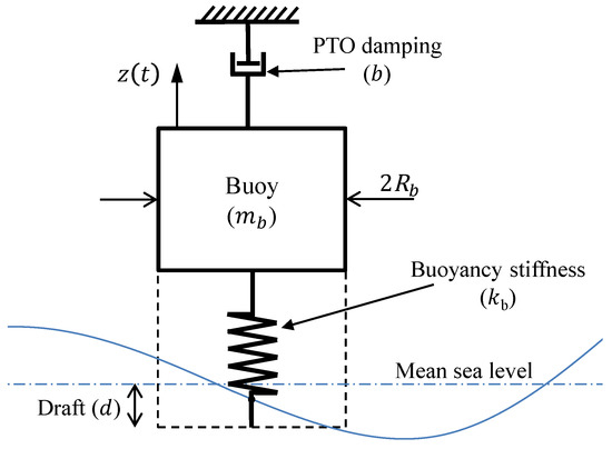
Figure 1.
Schematic of the SDOF heaving buoy WEC.
The radiation force consists of an added mass inertia force and a hydrodynamic damping force [22], both are functions of the buoy frequency of oscillation . The force can be represented using complex amplitudes as:
where is the complex amplitude of , is the added mass and is the hydrodynamic damping. The hydrodynamic coefficients and are derived as in [23] from the solution of the hydrodynamic boundary value problem. Considering the buoy is cylindrical with a radius , floating with a draft d in water of finite depth h, the coefficients and can be calculated from:
where , , and are functions in h, d, , and , as defined in Appendix A. and are modified Bessel functions of the first kind of order 0 and 1, respectively, and . For and , a value of 20 gives an acceptable convergence for the summation results [23].
The excitation force, can be represented by:
where is the complex amplitude of the heave excitation force. Considering low frequency waves (up to 2 rad/s), can be approximated to [24,25]:
where is a separation constant, and is:
where Y is the incident wave heave motion amplitude, is the Bessel function of the first kind of order zero, is its first derivative, is the Hankel function of first kind of order zero, and is its first derivative. The wave number is calculated by the dispersion equation in [21], which can be simplified for low frequencies (up to 2 rad/s) and water deeper than 10 m to .
Equation (1) can therefore be rewritten using complex amplitudes as:
Taking the inverse Fourier transform, the equation of motion in the time-domain can be represented as:
where is the radiation impulse response function. The hydrodynamic interaction is represented by the convolution integral in Equation (8), which can be approximated by a state-space description of the linear sub-system as:
where is the state vector of the sub-system, and , and, are the state-space companion-form realization matrices (see Appendix B) [21,26].
From Equation (8), the state-space description of the heaving system can be used to derive the heave motion displacement , as:
where is the system state vector, calculated from the state equation:
and , , and are the system state space model matrices, represented as:
2.2. Energy Frequency
The wave energy frequency can be calculated from the Pierson-Moskowiz spectrum which is an empirical relationship that defines the distribution of energy versus frequency, where the spectrum input is the wind speed. The spectrum formula is as follows [27,28]:
where is the power spectral density, is the frequency, U is the wind speed measured at above the sea surface, and and take the values of 0.0081 and 0.74, respectively. Spectrum calculations provide the energy frequency as:
In the case of irregular waves, the incident wave function can be calculated by the linear superposition of regular waves responses [29], each represented by a single sinusoidal wave using (5) as:
where is the random phase, and is the Pierson-Moskowitz power spectral density at the frequency , represented in Equation (16). The spectrum is divided into N equally spaced frequency divisions (here, ).
2.3. Available and Absorbed Power
The available power per unit width of incident waves (kW/m) is represented as a function in both and the significant wave height as:
where
is the spectrum zeroth moment (), and B is a constant, represented by .
The average absorbed power in the PTO damping is represented as [30]:
where is the velocity amplitude of the buoy, calculated using Equations (5), (11)–(16) and (18) at every frequency along the spectrum.
The capture width of the heaving buoy () is defined as the ratio between the power per unit width of the incident waves () and the absorbed power (), as:
3. Stiffness Reactive Controller
The proposed reactive loading controller varies the system effective stiffness using an external variable stiffness that increases the system restoring force . This controller also results in an increase in the system’s inertia and damping; hence, , , and in (7) become:
where , , and are the increase in the oscillating system stiffness, damping, and inertia due to the controller’s moving components. With the proposed controller, the magnitude of is controlled and varied dynamically according to the incident waves energy frequency so as to provide near-to-resonance operation for the heaving buoy WEC system. This maximizes oscillation amplitudes; hence, maximizes the power absorption in the system.
3.1. CVT Controller
As a proof of concept, we present a controller that includes a continuously variable transmission (CVT) system connected to the heaving buoy at one side and to an external stiffness at the other side, as shown in Figure 2. This controller tunes to the incident wave energy frequency that changes according to the sea state. The CVT system is a stepless drive that can provide wide continuous ranges of operating speed ratios . The speed ratio is varied such as the effect of the external stiffness () on the heaving buoy system is changed. The required speed ratio is calculated from the effective stiffness , necessary to achieve near-to-resonance operation. The controller stiffness is related to through:
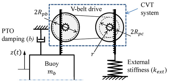
Figure 2.
Schematic of the CVT reactive stiffness controller.
Here, we used a V-belt drive CVT system that included two pulleys, connected to both the heaving buoy and the external stiffness by means of rack and pinion assemblies, as shown in Figure 2. The external stiffness is mounted onto a fixed foundation. The pulley system includes fixed and movable sheaves. The running radii and are changed through the axial positioning of the movable sheaves with respect to the fixed sheaves [21]. The speed ratio is changed by varying the ratio.
3.2. Inertia Effect of Cvt Mechanism
To tune the natural frequency of the system (), the effect of the CVT mechanism inertia must be included. The inertia varies with the change in the speed ratio ; hence, can be expressed as:
For the pulley-based CVT, corresponds to the inertia of the controller’s moving components and is calculated as:
where is the moment of inertia of the pulleys, and r is the pinion radius, shown in Figure 2. The added mass is negligible compared to and , thus, it is ignored. Equation (25) calculates the required speed ratio for a given excitation frequency as:
3.3. Controller Operating Bandwidth
Equations (25) and (27) indicate that the controller design parameters, including the range of values for the speed ratio and the external stiffness , depend on parameters that include the buoy physical dimensions and mass , in addition to the range of excitation frequencies for typical wind speeds. Here, we investigate the effects of the operation controller bandwidth on the calculated and using the system test parameters in Table 1:

Table 1.
CVT system simulation parameters.
Equations (24) and (27) were used to calculate and at different excitation frequencies , as presented in Figure 3. The controller bandwidth is represented by the frequency ratio , defined as the ratio between the incident wave energy frequency and the natural frequency of the buoy without the controller , i.e., . Similarly, the stiffness ratio is defined as the ratio between the effective stiffness and the buoyancy stiffness , i.e., .
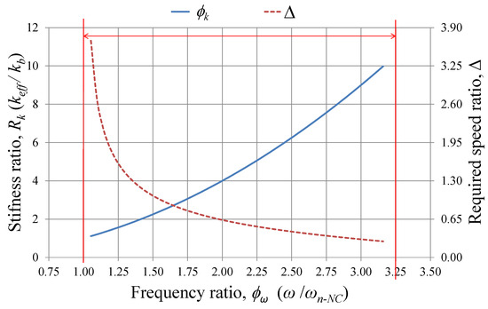
Figure 3.
Controller bandwidth: and at different excitation frequencies .
Equation (23) indicates that the minimum possible effective stiffness for the system equals the buoyancy stiffness, i.e., , which only occurs when the external stiffness is decoupled from the CVT controller (). This corresponds to the minimum operation frequency ratio (; thus, the controller cannot provide near-to-resonance operation at wave energy frequencies smaller than . Because of this limitation, the system should be designed so that is the minimum required operation frequency according to the sea state where the system is to be deployed (). The maximum operation frequency is selected such as to correspond to the minimum operation wind speed [21]. At this speed, the maximum external stiffness the controller can provide is achieved, which also corresponds to the minimum achievable speed ratio .
3.4. PTO Damping
Achieving near-to-resonance operation maximizes the undamped oscillation amplitudes; however, the PTO damping b needs to be carefully selected such that power absorption is maximized. Figure 4 shows the average absorbed power , and the capture width at different values for PTO damping b. Both and are defined by Equations (21) and (22), respectively. The results are presented in a root mean square form (RMS) at selected wind speeds U = 7, 10, and 12 m/s. Figure 4a,b shows that there is an optimal PTO damping value where both the power absorption and the capture width are maximum. Here, was approximately 1.2 kN.s/m.
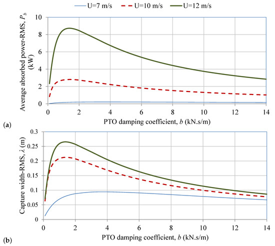
Figure 4.
Effect of the PTO damping b in irregular waves on (a) the average absorbed power in RMS, (b) the capture width in RMS.
3.5. Experimental Validation
Experiments were conducted to investigate the effect of varying the controller speed ratio on the proposed system’s frequency response. As a proof of concept, the system was simplified into a SDOF model, subjected to a displacement generated using a simple crank-slider exciting mechanism that simulates the incident wave heave excitation. Figure 5a shows a schematic of the experimental setup. The exciting mechanism consists of an AC motor (A) that displaces an oscillating mass (B) through a simple crank-slider mechanism (C). The mass is supported by exciting springs of stiffness (D), which simulates the effect of the buoyancy stiffness . This excitation is then transmitted to the controller mechanism through a rack (E), which in turn drives the CVT input sheaves (F) using a rack-pinion mechanism (G). The CVT output sheave (H) drives another rack-pinion mechanism (J), transmitting this motion to the external stiffness (K). The setup parameters included the following, as in Table 2:
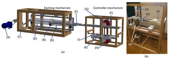
Figure 5.
The experimental setup: (a) 3D schematic showing the exciting and controller mechanism, (b) photograph of the controller mechanism (aligned vertically), showing the CVT.
Table 2.
Experimental validation parameters.
The system’s frequency response is represented by the displacement amplitude ratio (). Experiments were conducted at two CVT settings, Setting 1 and Setting 2, with speed ratios of 2.0 and 1.0, respectively. Using Equation (27), the system natural frequencies corresponding to these speed ratios are calculated as 6.23 and 7.06 rad/s, respectively.
At each setting, experiments were conducted at ranging between 2.5 rad/s to 15 rad/s, at 2.5 rad/s increments, to cover both the amplification and the isolation zones; hence, passing by the resonance frequency . An inverter was used to control the frequency of the power supplied to the AC motor (A); thus, control the frequency of the excitation. The input excitation amplitude Y was set at 100 mm. This corresponds to the stroke of the exciter’s crank-slider mechanism (C). The CVT was selected to have high mechanical friction () such that the effective damping () emulates that of a system integrated with a PTO system, causing a decrease in the displacement amplitude amplification ratio.
Figure 6 shows that the systems with Settings 1 and 2 were found to achieve their peak frequencies at 6.16 and 6.83 rad/s, respectively. These frequencies show good agreement with those calculated using (27) with a maximum error less than 4%. This validates the relation between the speed ratio and the system natural frequency, proving that changing , a non-resonating system can be tuned to operate at near-resonance state.
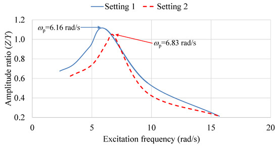
Figure 6.
Displacement amplitude ratio at different input excitation frequencies.
4. Discussion and Conclusions
This paper presents a short-term reactive loading control technique for heaving buoy WEC. The control is realized through the tuning of the system effective stiffness according to the incident waves energy frequency to achieve near-resonance operation; thus, maximum power absorption. The effective stiffness is changed by connecting the heaving buoy to an external stiffness , whose effect is continuously varied according to the energy frequency of the waves using a CVT controller mechanism. An analytical model was developed that calculates the CVT controller’s speed ratio needed to tune the non-resonating system to the sea wave frequencies, and operate at near-resonance state. MATLAB codes of the analytical model are available as supplementary material.
Experiments were performed, where the resulting system frequencies were found to be in good agreement with those calculated analytically, with the maximum error less than 4%. This validates the proposed concept. The analytical model reveals that both and can be calculated for most heaving buoy WECs provided that the following are known: the buoy’s dimensions, buoy mass, in addition to the range of frequencies for typical wind speeds. This new control technique is considered a quick reactive loading control and has the advantage of working over longer time periods without continuous demands from the PTO as in phase control techniques.
The effects of the PTO damping on the buoy displacement amplitude and absorption efficiency were investigated analytically. Results indicated that an optimum PTO damping should be selected based on both the power absorption , and the displacement amplification ratio . Both low and high damping values of b are not preferred because of the decreased power absorption efficiency; low b values cause the PTO system to absorb little energy from the oscillations, while high b values decrease the amplitudes of the system. As the system is tuned to operate at near-resonance, care must be taken such that the amplitudes do not increase to levels at which the vibrating system may not structurally withstand. In such cases, it is not preferable for such WEC systems to operate at the optimum value of the PTO damping , at which the oscillation and velocity amplitudes, z and , are very high. Values around the optimum should be more appropriate values for both reaching good power absorption, and avoid excessive amplitudes.
Supplementary Materials
MATLAB codes of the analytical model are available online at https://www.mdpi.com/1996-1073/14/1/44/s1.
Author Contributions
Conceptualization, A.H.S., S.M.M. and Y.H.A.; data curation, A.H.S.; methodology, A.H.S., S.M.M. and Y.H.A.; software, A.H.S.; validation, A.H.S., S.M.M. and Y.H.A.; formal analysis, A.H.S.; investigation, A.H.S.; writing—original draft preparation, A.H.S. and Y.H.A.; writing—review and editing, A.H.S., S.M.M. and Y.H.A.; visualization, A.H.S. and Y.H.A.; supervision, S.M.M. and Y.H.A.; project administration, S.M.M. and Y.H.A.; software, A.H.S.; resources, A.H.S. and S.M.M. All authors have read and agreed to the published version of the manuscript.
Funding
This research received no external funding.
Institutional Review Board Statement
Not applicable.
Informed Consent Statement
Not applicable.
Data Availability Statement
No new data were created or analyzed in this study. Data sharing is not applicable to this article.
Conflicts of Interest
The authors declare no conflict of interest.
Abbreviations
The following abbreviations are used in this manuscript:
| WEC | Wave energy converter |
| SDOF | Single-degree-of-freedom |
| PTO | Power take-off system |
| CVT | Continuous variable transmission |
Appendix A
The variable is calculated from:
The Kronecker delta function, for , and for . The variables and , and are:
where is modified Bessel function of the second kind of order 0, and is its first derivative. is the first derivative of the modified Bessel function of the first kind of order 0.
Appendix B
The companion-form realization, which is one of many possible realizations for this state-space model, is used with the matrices , and, defined as [26]:
where and can be calculated for minimizing the following target function [26]:
where is a weight function to be chosen, and is the value of the impulse response function at chosen instants . The target function Q is minimized by the pattern-search minimization method. A reasonably good approximation is obtained even if n is a rather small integer. The selected value for calculation is .
References
- Pecher, A.; Peter Kofoed, J. Handbook of Ocean Wave Energy; Springer Nature: Berlin/Heidelberg, Germany, 2017. [Google Scholar]
- Antonio, F.D.O. Wave energy utilization: A review of the technologies. Renew. Sustain. Energy Rev. 2010, 14, 899–918. [Google Scholar] [CrossRef]
- De Backer, G. Hydrodynamic Design Optimization of Wave Energy Converters Consisting of Heaving Point Absorbers. Ph.D. Thesis, Ghent University, Ghent, Belgium, 2013. [Google Scholar] [CrossRef]
- Korde, U.A.; Ertekin, R.C. Wave energy conversion by controlled floating and submerged cylindrical buoys. J. Ocean Eng. Mar. Energy 2015, 1, 255–272. [Google Scholar] [CrossRef][Green Version]
- Wang, L.; Isberg, J.; Tedeschi, E. Review of control strategies for wave energy conversion systems and their validation: The wave-to-wire approach. Renew. Sustain. Energy Rev. 2018, 81, 366–379. [Google Scholar] [CrossRef]
- Coe, R.G.; Bacelli, G.; Wilson, D.G.; Abdelkhalik, O.; Korde, U.A.; Robinett, R.D., III. A comparison of control strategies for wave energy converters. Int. J. Mar. Energy 2017, 20, 45–63. [Google Scholar] [CrossRef]
- Faedo, N.; Olaya, S.; Ringwood, J.V. Optimal control, MPC and MPC-like algorithms for wave energy systems: An overview. IFAC J. Syst. Control 2017, 1, 37–56. [Google Scholar] [CrossRef]
- Hals, J.; Falnes, J.; Moan, T. A comparison of selected strategies for adaptive control of wave energy converters. J. Offshore Mech. Arct. Eng. 2011, 133, 031101–031113. [Google Scholar] [CrossRef]
- Lynn, P.A. Electricity from Wave and Tide: An Introduction to Marine Energy, 1st ed.; John Wiley & Sons Ltd.: Hoboken, NJ, USA, 2013; pp. 1–266. [Google Scholar] [CrossRef]
- Lucas, J.; Salter, S.; Cruz, J.; Taylor, J.; Bryden, I. Performance Optimisation of a Modified Duck Through Optimal Mass Distribution. In Proceedings of the 8th European Wave and Tidal Energy Conference (EWTEC), Uppsala, Sweden, 7–10 September 2009; pp. 270–279. [Google Scholar]
- Piscopo, V.; Benassai, G.; Cozzolino, L.; Della Morte, R.; Scamardella, A. A new optimization procedure of heaving point absorber hydrodynamic performances. Ocean Eng. 2016, 116, 242–259. [Google Scholar] [CrossRef]
- Costa, P.R.; Garcia-Rosa, P.B.; Estefen, S.F. Phase control strategy for a wave energy hyperbaric converter. Ocean Eng. 2010, 37, 1483–1490. [Google Scholar] [CrossRef]
- Flocard, F.; Finnigan, T. Increasing power capture of a wave energy device by inertia adjustment. Appl. Ocean Res. 2012, 34, 126–134. [Google Scholar] [CrossRef]
- Yavuz, H.; Stallard, T.J.; McCabe, A.P.; Aggidis, G.A. Time series analysis-based adaptive tuning techniques for a heaving wave energy converter in irregular seas. Proc. Inst. Mech. Eng. Part A J. Power Energy 2007, 221, 77–90. [Google Scholar] [CrossRef]
- Shek, J.; Macpherson, D.; Mueller, M.; Xiang, J. Reaction force control of a linear electrical generator for direct drive wave energy conversion. IET Renew. Power Gener. 2007, 1, 17. [Google Scholar] [CrossRef]
- Schoen, M.P.; Hals, J.; Moan, T. Wave prediction and fuzzy logic control of wave energy converters in irregular waves. In Proceedings of the 2008 Mediterranean Conference on Control and Automation, MED’08, Ajaccio, France, 25–27 June 2008; pp. 767–772. [Google Scholar] [CrossRef]
- Wei, C.; Jing, X. Vibrational energy harvesting by exploring structural benefits and nonlinear characteristics. Commun. Nonlinear Sci. Numer. Simul. 2017, 48, 288–306. [Google Scholar] [CrossRef]
- Li, M.; Jing, X. Novel tunable broadband piezoelectric harvesters for ultralow-frequency bridge vibration energy harvesting. Appl. Energy 2019, 255, 113829. [Google Scholar] [CrossRef]
- Budal, K.; Falnes, J. Interacting point absorbers with controlled motion. In Power from Sea Wave; Academic Press: London, UK, 1980; pp. 381–399. [Google Scholar]
- Salter, S.H.; Taylor, J.R.; Caldwell, N.J. Power conversion mechanisms for wave energy. J. Eng. Marit. Environ. 2002, 216, 1–27. [Google Scholar] [CrossRef]
- Sakr, A.H.; Anis, Y.H.; Metwalli, S.M. System frequency tuning for heaving buoy wave energy converters. In Proceedings of the IEEE/ASME International Conference on Advanced Intelligent Mechatronics, AIM, Busan, Korea, 7–11 July 2015; pp. 1367–1372. [Google Scholar] [CrossRef]
- Hals, J. Modelling and Phase Control of Wave-Energy Converters. Ph.D. Thesis, Department of Marine Technology, Norwegian University of Science and Technology, Trondheim, Norway, 2010. [Google Scholar]
- Bhatta, D.D. Computation of added mass and damping coefficients due to a heaving cylinder. J. Appl. Math. Comput. 2007, 23, 127–140. [Google Scholar] [CrossRef]
- Finnegan, W.; Meere, M.; Goggins, J. The Wave Excitation Forces on a Floating Vertical Cylinder in Water of Infinite Depth. In Proceedings of the World Renewable Energy Congress, Linköping, Sweden, 8–13 May 2011; pp. 2175–2182. [Google Scholar] [CrossRef]
- Finnegan, W.; Goggins, J. Numerical simulation of linear water waves and wavestructure interaction. Ocean Eng. 2012, 43, 23–31. [Google Scholar] [CrossRef]
- Yu, Z.; Falnes, J. State-space modelling of a vertical cylinder in heave. Appl. Ocean Res. 1995, 17, 265–275. [Google Scholar] [CrossRef]
- Pierson, W.J., Jr.; Moskowitz, L. A proposed spectral form for fully developed wind seas based on the similarity theory of SA Kitaigorodskii. J. Geophys. Res. 1964, 69, 5181–5190. [Google Scholar] [CrossRef]
- Carter, D.J. Estimation of Wave Spectra from Wave Height and Period; Technical Report; Institute of Oceanographic Siences: London, UK, 1982. [Google Scholar] [CrossRef]
- Borgman, L.E. Ocean Wave Simulation for Engineering Design; Technical Report; University of California: Berkeley, CA, USA, 1967. [Google Scholar]
- Falnes, J.; Kurniawan, A. Ocean Waves and Oscillating Systems: Linear Interactions Including Wave-Energy Extraction; Cambridge University Press: Cambridge, UK, 2020; Volume 8. [Google Scholar]
Publisher’s Note: MDPI stays neutral with regard to jurisdictional claims in published maps and institutional affiliations. |
© 2020 by the authors. Licensee MDPI, Basel, Switzerland. This article is an open access article distributed under the terms and conditions of the Creative Commons Attribution (CC BY) license (http://creativecommons.org/licenses/by/4.0/).