Article

Cluster-Based Method to Determine Base Values for Short-Term Voltage Variation Indices

by
Paulo Vitor Grillo de Souza
1,2,*,
José Maria de Carvalho Filho
1,
Daniel Furtado Ferreira
2,
Jacques Miranda Filho
3,
Homero Krauss Ribeiro Filho
4 and
Natanael Barbosa Pereira
5
1
Institute of Electrical Systems and Energy, Federal University of Itajubá, Itajubá, MG 37500-903, Brazil
2
Statistics Department, Federal University of Lavras, Lavras, MG 37200-000, Brazil
3
Electrotechnical Coordination, Federal Institute of Espírito Santo, Vitória, ES 29040-780, Brazil
4
Transmissora Aliança de Energia Elétrica S.A—TAESA, Brasília, DF 70385-080, Brazil
5
Energias de Portugal—EDP, São José dos Campos, SP 12210-010, Brazil
*
Author to whom correspondence should be addressed.
Energies 2021, 14(1), 149; https://doi.org/10.3390/en14010149
Submission received: 16 November 2020 / Revised: 24 December 2020 / Accepted: 26 December 2020 / Published: 30 December 2020
(This article belongs to the Special Issue Analysis and Experiment for Electric Power Quality)

Abstract

:
This paper proposes a methodology for establishing base values for short-term voltage variation indices. The work is focused on determining which variables best describe the disturbance and based on that, establish clusters that allow a more adequate definition of base values for the indices. To test the proposed methodology, real data from 19 distribution systems belonging to a Brazilian electricity utility were used and consequently the index presented in the country standard was considered. This study presents a general methodology that can be applied to all distribution systems in Brazil and could serve as a guide for the regulatory agencies in other countries, to establish base values for their indices. Furthermore, the objective is to show through the results that, with the database used is possible to establish clusters of distribution systems related to the voltage sag and with these establish a base impact factor, distinct for each distribution system.

1. Introduction

1.1. Relevance

Due to technological advances, always based on improving the productivity of industrial processes and providing well-being to all people, electro-electronic devices have had a great entry in the domestic sector but mostly at manufacturing sector. However, in general this electronics-based equipment has greater sensitivity to disturbances that affect the power quality, especially those related to short-term voltage variations. When there is a voltage sag in the electrical system, some industrial plant equipment may present malfunctions that could compromise the production process, or in extreme cases, it could cause a complete cessation of operations. Regardless of the type of interruption that occurs in the industrial process, there will always be losses due to lost productivity, loss of raw materials and the repair and replacement of damaged equipment [1].
The standard [2] presents methods for assessing the severity of individual voltage sag events (single-event characteristics) and identifies voltage sag indices to quantify the performance of multiple events in a specific location (single-site indices) or for the whole system (system indices), as an example the SARFI indices, voltage sag tables, voltage sag energy and voltage sag severity. References [3,4] do not present an index to assess voltage sags, and only suggest a way to account for voltage sags, using a table divided into residual voltage ranges and event duration ranges. Document [5] aims to standardize the approach in South Africa to the characterization of voltage sag performance, seven voltage sag categories have been established (Y, X1, X2, S, T, Z1, Z2), based on a combination of customer load compatibility and network protection characteristics. This standard also presents characteristic values for the number of sag events in each category obtained from a historical of the monitored sites. Currently [6] establishes an index called impact factor (IF in Equation (10)) to assess the severity of the incidence of short term voltage variations on substation buses and proposes a single reference value for this index of 1 p.u. One of the most controversial issues among the electricity sector agents was the reference value of 1 p.u. suggested for the IF index, as generally, large consumers of energy, have pointed out that the proposed value is soft and does not reflect the real needs of industrial consumers, because it allows many process stoppages to happen. Despite the numerous ways of assessing the voltage sags proposed in the standards [2,3,4,5,6], none of them establishes a compliance criterion, that is, they do not present limit values for their indices. Therefore, although voltage sags have a major negative economic impact for companies, electricity utilities are not penalized if the industrial consumer suffers process stoppages. For that reason, the question is how to properly establish limits for the IF index, since Brazil has a large territorial extension, it is one of the countries with the largest interconnected electrical system, has a great diversity of vegetation and climate. As distribution systems of different regions are prone to different levels of variables influencing the voltage sags occurrence, a credible way is to set distinct limits according to the characteristics of each distribution system. Regarding to the improvement of the standard, this work is proposing a methodology for the establishment of the base impact factor, considering distribution system clusters that have similar characteristics in relation to the variables that influence the occurrence of voltage sags, it is worth mentioning that the proposed methodology is generic and can be applied by regulatory agencies in other countries to establish base values for their indices.

1.2. State of Art

A survey of the main research databases in the field of electrical engineering, found articles that use cluster analysis to characterize the power quality phenomena. The following is a summary of each of these works. In [7] a method for the evaluation of the events of power quality considering different network operating conditions was proposed. The measured data may depend on the load changes, generation and different network configurations. For this reason, the author of the paper uses clustering techniques to divide acquired data into groups that reflect operating conditions. In work [8], a technique based on graphical cluster analysis was developed to be implemented in a smart power quality analyzer, to monitor electrical networks. In the presence of a fault, the equipment starts the measurement procedure and higher order statistics are calculated in the time domain to allow classification. The results showed the division into two groups of events (voltage sags and transients), with an accuracy of 80%. The paper [9] presents an algorithm that uses the k-means method to recognize and classify the voltage sags of measurement data from a large power grid in Shenzhen (China). The results showed that nearly all voltage sags disturbances can be classified into 11 clusters that probably represent the characteristics and causes of most events occurring in typical distribution systems. In [10], a method developed to determine the optimal number of groups to be formed in power quality measurement data is presented using a data mining algorithm based on the minimum message length (MML) technique. To test the proposed method, three different databases were used, and the test results confirmed the effectiveness of the proposed method, finding the optimal number of groups. A new approach to identify the severity profile of busbar voltage sags was introduced in [11], Voltage sags data caused by faults in all nodes of the system are separated into clusters using the k-means technique. By implementing the method, as a result, information is obtained from the buses that have the lowest occurrence of severe events, hence allowing the choice of installation of sensitive loads at such points of the system. In addition, knowing the most affected buses, the allocation of attenuation devices such as dynamic voltage restorers (DVRs) can be better evaluated. It is presented in [12] a hybrid model for power quality analysis composed by a modification of the fuzzy min-max neural network (FMM) method added to a modification of the clustering tree (CT) technique. The results were compared with those obtained when applying other clustering algorithms, indicating a better accuracy of the proposed new method. A methodology for detecting and classifying power quality disturbances using a Stockwell transform was developed in [13]. The disturbances were generated by MatLab according to the standards established in the IEEE—1159. Several signal characteristics were extracted from the S-transform based multiresolution analysis. These characteristics are used to classify the disturbances by the fuzzy c-means clustering method. The effectiveness of the proposed algorithm was verified by satisfactory results from several case studies, showing an assertiveness of 99%. Reference [14] proposes a new method for reducing the training set size for the K–nearest neighbors (KNN) algorithm. The proposed method is based on an iterative process. Experimental results showed that the accuracy after sample reduction by recursive process had no difference compared to the original training set. However, the classification of a new signal became faster. For a signal from a real measuring device, the classification time has been reduced from 1.35 s to 0.09 s. The work [15] proposes a method to comprehensively evaluate the power quality based on the maximum tree (MT) algorithm for clustering by the fuzzy method. For the test, 4 indicators were selected: voltage deviation, frequency variation, voltage unbalance and harmonic. The results achieved in a practical case proved the viability of the method, which provides some scientifically based guidelines for the consumer to select the electricity utility and adjust the price paid for the energy according to the quality offered. The paper [16] proposes a methodology to locate the source of voltage sags, initially cluster analysis is used to divide data of voltage signals measured in different nodes into groups. Then, the set of decision rules is defined using the partial decision trees algorithm, which will confront the characteristics of each cluster and define which group the location of the disturbance source fits into. The IEEE 34-bus test feeder system was used to evaluate the methodology and the results showed a hit rate greater than 98%. The work [17] proposes and evaluates an alternative methodology to characterize and classify voltage sags. PCA and K-means clustering technique are applied to identify RMS voltage patterns and reduce the number of RMS voltage profiles representative of the events considered. Real data from 300 events collected at a wind farm in Spain were used to validate the methodology. The proposed methodology proved to be efficient to assess a large number of events. The paper [
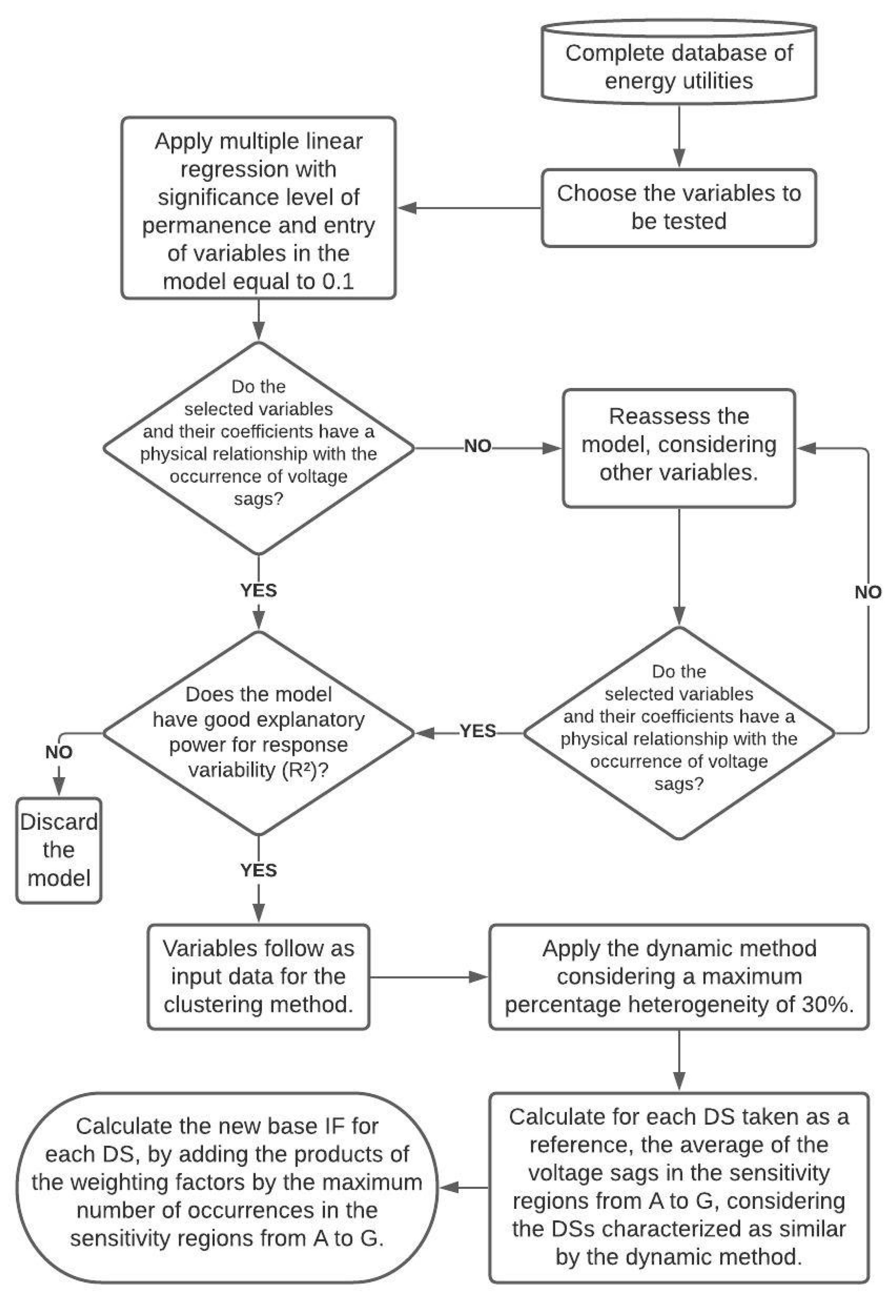
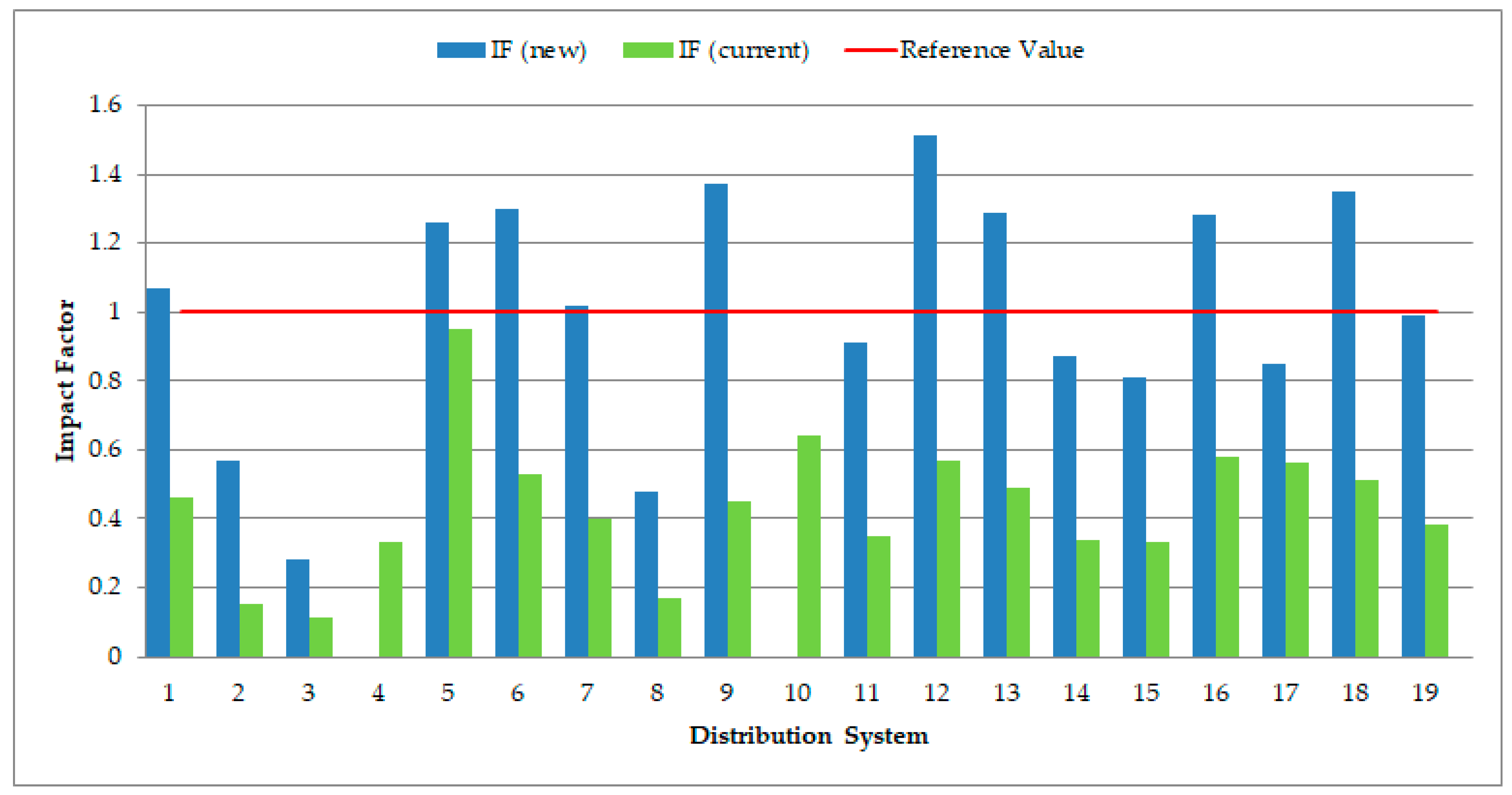
18] based on a statistical procedure that considers the correlation between the index and the number of equipment trips, proposes a methodology to determine different sensitivity regions and weighting factors from those established in [6]. Therefore, it proposes an improvement of the standard [6]. The research conducted in [19] shows a methodology for clustering distribution systems considering the variables related to voltage sags. The methodology is summarized in four processes: selection of the variables by their correlation with the frequency of voltage sags, implementation of the cluster analysis considering various methods for further investigation of the most appropriate, evaluation of the methods that generated the best clusters through analysis of variance between the response and the generated membership and finally robustness analysis made by including small noises in the input variable, observing which of the methods is more assertive in this condition. The results showed that Ward’s method was the most appropriate to the considered database. In the paper [20] it is proposed to apply principal component analysis (PCA) to reduce 32 variable input data (with some level of redundancy) by seven principal components (PCs) which account for 97.9% of the information from the original variables, and from these PCs form clusters of substations, using the Ward’s method, considering the Euclidean distance between the elements. The formed clusters allowed to classify the distribution systems in three categories regarding the number of occurrence of voltage sags (high, medium and low levels). Studies conducted in [21] show a novel methodology to increase discriminatory power in the estimation of voltage sag patterns using ellipsoidal functions. Ward’s method was used to form clusters of substations with a similarity level to voltage sags, three distinct groups were found with small, medium and large amount of voltage sags. The work [21] is an evolution of that presented in [20]. The method showed results that are more precise, stable and reliable.
In articles [7,8,9,10,11,12,13,14,15,16,17], clustering techniques are used for purposes different from the objective of this paper, such as monitoring, identification and classification of events, location of the source and pattern recognition of voltage sags. These references were presented to identify the application of cluster analysis in the power quality area.
The paper [18] focuses on proposing different sensitivity regions and weighting factors from those established in [6]. While this paper, assuming that the regions of sensitivity and weighting factors established in [6] are adequate, using cluster analysis, proposes new values for the maximum frequency of occurrence of voltage sags and consequently a new base impact factor. Therefore, the works are distinct, although complementary.
Articles [19,20,21] test several methods of clustering, with the objective of evaluating which one is best suited to form groupings of distribution systems regarding the frequency of voltage sags. These works are the ones that are most related to this paper, but they are focused only on forming the groups, while this paper besides forming the groups, uses this information to establish a base value for the voltage sag index, distinct for each distribution system according to the performance of similar systems. Therefore, this paper complements the studies conducted in [19,20,21] with the aim of promoting improvements in [6]. None of the papers found use clustering techniques to determine the base values for short-term voltage variation indices, showing the innovation of the proposed methodology.

2. Theory

2.1. Multiple Regression Analysis

A regression model that contains more than one predictor is called a multiple regression model [22]. The purpose of multiple regression analysis is to use independent variables which values are known to predict the values of the dependent variable selected by the researcher. Typically, the dependent or response variable, y, may be related to k independent or predictor variables. The generic model of multiple linear regression with k variables is presented in Equation (1):
y = β 0 + β 1 x 1 + β 2 x 2 + + β k x k + ϵ
Equation (1) describes a hyperplane in the k-dimensional space of the predictor variables. The parameters β j are called partial regression coefficients [22]. β j can be interpreted as the expected change in y due to the increase of one unit in xj, with the other variables xk, k ≠ j fixed. Suppose there are k predictor variables and n observations. This model is a system of n equations, which can be expressed in matrix notation by Equation (2):
y = X β + ϵ
where y = [ y 1 y 2 y n ] X = [ 1 x 11 x 1 k 1 x 21 x 2 k 1 x n 1 x nk ] β = [ β 0 β 2 β k ] ϵ = [ ϵ 1 ϵ 2 ϵ n ] .
The least-squares method can be used to estimate regression coefficients in the multiple regression model. Equation (3) gives the least squares estimate for β [23]:
β ^ = ( X X ) 1   X y
The adequacy of the model is evaluated through hypothesis tests related to its parameters. Therefore, the hypothesis test is given by Equation (4):
H 0 :   β i = 0 H 1 :   β i 0 i = 0 , 1 , ,   k
If the p-value corresponding to the coefficient of a variable is inferior than or equal to a predetermined significance level α, H0 is rejected and it is concluded that this coefficient is non-zero, i.e., the variable in question is a significant addition to the model. Otherwise, H0 is not rejected and it is concluded that such variable has a non-significant effect. Another way of expressing the forecast accuracy level is with the coefficient of determination (R2), as shown in Equation (5):
R 2 = SQ Reg SQ T = i = 1 n ( y i ^   y ¯ ) 2 i = 1 n ( y i   y ¯ ) 2
Thus R2 is a global statistic to evaluate how much of the response variability of y is explained by the independent variables. In most surveys, there are a large number of independent variables available that can be chosen for inclusion in the regression equation. The step of selecting which variables will be part of the model is an important point in the model estimation process [23]. This research tested three sequential search methods to select variables called stepwise, forward and backward. Probably the most used variable selection technique is stepwise regression. A sequence of regression models is constructed iteratively, adding or removing variables at each stage. The criteria for removing or adding a variable at any stage are expressed in terms of a partial F test. To begin the process, the independent variable with the highest correlation coefficient with the dependent variable is chosen to generate a simple regression model. The next independent variables selected are based on their incremental contribution (partial correlation) to the regression equation. Each new independent variable introduced in the model is examined by the F test if the contribution of the variables that are already in the model remains significant, given the presence of the new variable. If not, the stepwise estimation allows variables already in the model to be eliminated. The procedure continues until all independent variables not yet present in the model have their inclusion evaluated and the reaction of the variables already present in the model is observed when these inclusions occur [23].
In the forward selection procedure, variables are added to the model one at a time, as long as their partial value of F exceeds a previously established limit. That is, this technique can be considered a variation of the regression stepwise.
The backward elimination algorithm begins with all k model predictors. Then the predictor with the lowest F statistic is removed if that F statistic is insignificant. Subsequently, the model with k–1 predictors is adjusted and the next predictor for potential elimination is found. The algorithm ends when no more predictors can be eliminated [22].

2.2. Cluster Analysis (Dynamic Method)

Cluster analysis is the set of multivariate techniques whose main purpose is to aggregate objects, items or individuals based on their characteristics [23]. The basic criteria used to group objects is their similarities. In this manner, objects belonging to the same cluster are similar to each other concerning the variables that were measured in them, and the elements of distinct clusters are dissimilar for these same variables [24].
To decide whether two database elements can be considered as similar or not, mathematical metrics are used. In this study, Euclidean distance was used as a measure of dissimilarity. Considering two elements Xl and Xk, l ≠ k, the Euclidean distance between them is defined by Equation (6):
d ( X l , X k ) = [ i = 1 p ( X il X ik ) 2 ] 1 2    
Clustering techniques are classified into two types: non-hierarchical and hierarchical, and these are again classified into agglomerative and divisive [24]. Although hierarchical and non-hierarchical methods have certain advantages, its application may not produce good results when analyzing the elements located at the borders between the different groups, as shown in Figure 1.
In Figure 1, it is noted that elements I and L belong to cluster 1 and the element F belongs to cluster 2. Therefore, such elements will be represented by the characteristics of their respective centroids. However, it is evident that the elements I, L and F are much more similar to each other than to their own centroids. To get around this problem [25] has created a new method, which works by establishing dynamic (changing) clusters from each element. In the dynamic method, for each element taken as reference, a grouping of elements that are most comparable to the so-called reference element will be formed.
In this method there is no formation of fixed clusters, as if there were distinct clusters for each element. This method is very appropriate when the sense of belonging to each cluster is extremely relevant. The algorithm for this technique consists of:
  • Each element is adopted as the centroid of a group to be created;
  • Once the centroid is defined, the distance of all elements to this centroid is determined;
  • A cut-off criterion is established for the degree of similarity between the centroid and the elements;
  • Each centroid is grouped with the most representative elements based on their similarities;
  • The process is repeated for each of the elements.
The drawback of the dynamic method is that each sample element will generate a cluster. Consequently, for applications that have many elements, the algorithm must be implemented computationally.

2.3. Short-Term Voltage Variations and Index

Short-term voltage variations are defined as random events characterized by significant deviations in the voltage RMS value over a short period and are divided into voltage sags, swells and interruptions.
Voltage sags are the most frequent events among short-term voltage variation (STVV), having a much higher occurrence rate than voltage swells. The IEEE 1564 standard recommends that the handling of voltage sag and voltage swell events be done separately, due to the different effects they cause on equipment [2]. Therefore, this paper will prioritize the study of voltage sags. Although there are many studies and standards focused on voltage sags, there is no international consensus on which index best characterizes the disturbance. Standard [6] presents as parameters of an STVV the event amplitude (Equation (7)), the event duration (Equation (8)) and as an index of a bus or system the frequency of occurrence of events (Equation (9)):
V e = V res V ref × 100
where Ve is the event amplitude (in %), Vres is the residual voltage of the event (in Volts) and Vref is the reference voltage (in Volts):
Δ t e = t f t i
where ∆te is the event duration, tf is the event end time and ti is the event start time:
f e = n
where fe is the frequency of events and n is the number of events recorded in the period.
Some standards such as [2,3,4,5] propose that event stratification be done in tables with certain amplitude and duration ranges.
Taking into consideration the particularities of the electrical system, the standard [6] establishes as shown in Table 1, nine sensitivity regions, to correlate the importance of each event with the sensitivity levels of different loads [18].
To describe the severity of the incidence of events in a single index, the Impact Factor (IF) index was established in [6], which has a 30 consecutive days calculation period, and is calculated by Equation (10):
IF = i = A I ( f ei × fp i ) IF base
where fei is the frequency of events over 30 consecutive days for each sensitivity region i, with i = A through I, fpi is the weighting factor for each sensitivity region and IFbase is the base impact factor, calculated considering the weighting factors and the maximum frequency of occurrence for each sensitivity region. The maximum frequency of occurrence for each sensitivity region is presented in Table 2.
The weighting factors were stipulated by the regulatory agency in order to consider in the equation the sensitivity of the loads normally present in the industries, giving more weight to severe events, which have a high probability of causing equipment shutdowns and less weight for mild events, with a low probability of causing shutdowns. The weighting factor (fp) for each sensitivity region and also the base impact factor are shown in Table 3.
The base impact factor currently adopted is the same for all distribution systems, not considering the levels of the variables that influence the occurrence of the event. The reference value set in [6] for the impact factor index for distribution systems is 1.0 p.u.
Therefore, the objective of this work is to define different base impact factors for each distribution system taking into account the performance of distribution systems that have similar characteristics with respect to the variables that influence the occurrence of voltage sags.

3. Material and Methods

3.1. Material

To make the proposed methodology applicable to all distribution systems with 1 kV < Vnominal< 69 kV in Brazil, starting from a larger database that is mandatorily sent by all electricity utilities to the regulatory agency were chosen by a specialist 9 attributes that include technical information of the distribution network that may be related to the occurrence of voltage sags. Besides the attributes, it is necessary the information that will serve as a goal to form clusters, which in the specific case of this research considered the frequency of occurrence of the phenomena. The average monthly frequency of voltage sag was obtained from measurements in 19 distribution systems belonging to a Brazilian electricity utility.
The complete database containing the values of the considered attributes and the frequency of voltage sags measured in each distribution system (DS) is shown in Table 4. The meaning of each abbreviation is listed in the Abbreviations section below.
The number of feeders, is obtained by counting in the substation diagram, the number of rural consumer units provided by the electricity utility, the atmospheric discharge density was estimated from historical meteorological data, the percentage of remaining vegetation was established by processing satellite images, the percentage of single-phase transformers was obtained by the ratio of the number of single-phase transformers to the total number of transformers in the distribution system, the percentage of rural transformers was obtained by the ratio of the number of rural transformers to the total number of transformers in the distribution system, the average feeder length was obtained by the ratio of the total length of the distribution network to the number of feeders, the fault rate was obtained by averaging historical data, the vulnerability area refers to the substation bus and it was calculated considering failure impedance equal to zero. With the distribution system modeled in a simulation software, short-circuits are applied to all nodes in the network while the voltage on the substation bus is monitored, to check for voltage sag. All types of short circuit were considered and weighted by the typical probability of occurrence. The average monthly frequency of voltage sags was obtained through meters that were installed in the substations and measured during one year.

3.2. Methods

The proposed methodology can be summarized in the following steps:
  • Variables selection through sequential search methods (explained in Section 2.1).
  • Formation of distribution systems clusters through the dynamic method, using as input variables those selected in the previous step (explained in Section 2.2).
  • Establishment of the base impact factor for each distribution system by averaging the frequency of occurrence found in similar distribution systems, this is the main point of the proposed methodology and will be exemplified in Section 4.3.
The flowchart in Figure 2, presents in more detail the process of the proposed methodology.

4. Case Study and Results

4.1. Variable Selection

Given the number of variables available for analysis, and knowing the sensitivity that the clustering method has when considering a large number of input variables, a step in variable selection has been performed to define the smallest possible set that has a good capacity to explain the variability of the response. For this step, the stepwise regression, backward elimination, and forward selection procedures were tested. Considering a level of significance for entry and removal of variables in the model equal to 0.1 and applying the three regression techniques tested, the same model was obtained, whose main parameters (R2, coefficients, regression equation) are shown in the Table 5.
The generated model shows that all the selected variables presented P-Value below the 0.05 threshold, indicating to be significant in the model. Also, the VIF values are all less than 5, showing low multicollinearity between the selected variables. However, the parameter normally used to verify the adequacy of the model is R2, the model adjusted for the number of occurrences of voltage sags, presented R2 = 74% (satisfactory value), representing a model that although parsimonious (a small number of variables) still explains the variability of the response. Thus, in the subsequent steps of the methodology, the variables (PC_VRA—“percentage of remaining vegetation”, PC_TD_1F—“percentage of single-phase transformers”, FR—“fault rate” and VA—“vulnerability area”) will be used. It is noteworthy that any model found by the statistical method should be appreciated by a specialist, to verify the selected variables and their coefficients, as to the physical meaning they have with the phenomenon under analysis. Making this critical analysis of the obtained model, it is valid to select the variable “percentage of remaining vegetation”, since a short circuit source in the networks is the trees that can touch it. The variable percentage of single-phase transformers indirectly brings information on the percentage of rural networks, since single-phase transformers are commonly used in these. This way, the variable also has an explanation from electrical engineering, since rural networks are more exposed to the action of animals and tend to have less frequent maintenance compared to urban networks. The fault rate variable is also related to the occurrence of voltage sags, as some faults generate these events. The variable vulnerability area is strongly related to the occurrence of the phenomenon since it represents the area under which the occurrence of a fault will generate voltage sag. It is also noted that the coefficients linked to the variables present in the model are in agreement with the expected since these selected variables have a direct relation, i.e., an increase in the value of some predictor increases the value of the response.

4.2. Clustering Analysis

For the implementation of the dynamic method, it is necessary to create tables by increasingly sorting the distances between elements for each element taken as reference. For example, considering DS 8 as a reference, Table 6 shows the distances between elements.
Percent heterogeneity is obtained by dividing the distance values by the maximum distance (denominator of Equation (11)). The maximum distance will be the distance between the reference DS and a hypothetical DS whose standardized attributes are three times the value of the reference DS attributes, in other words, a DS that is 3 standard deviations from the reference DS. Thus, the percentage heterogeneity formula is presented in Equation (11):
Heterogeneity =   Distance k · 3 2 = Distance 4 · 3 2 = Distance 6
where k is the number of attributes. From the analysis of Table 6, considering maximum percentage heterogeneity of 30%, DS 8 has 11 similar DSs.

4.3. Setting the Base Impact Factor

To establish the base impact factor, it is proposed to use the average of the values of the monthly average frequency of voltage sags in each sensitivity region in the DSs that most closely resemble the DS taken as reference. Starting with a determination of the maximum expected number of occurrences in each sensitivity region, with these values and using the weighting factors used by [2], a different IFbase is calculated for each distribution system. The differentiation of IFbase from each system allows the reference value set by [6] of 1 p.u. be maintained, but each DS will have a different goal according to the characteristics that most contribute to the occurrence of the phenomenon and according to the performance of systems that have similarities concerning these characteristics. Taking as an example the DS 8, Table 7 shows the average monthly frequency of voltage sags measured in these distribution systems stratified in sensitivity regions A to G.
Considering the average of the data in bold type present in each column of Table 7, the maximum number of occurrences expected for each sensitivity region is obtained for DS 8. Table 8 shows the sensitivity regions A to G considered in the Impact Factor calculation, the weighting factor and the maximum number of occurrences relative to each sensitivity regions used by [6] and the calculated by the proposed procedure.
With the values of the maximum occurrences of DS 8, the new base impact factor for this system is calculated by summing the weighting factor products by the maximum occurrences, resulting in 0.75.
It is observed that the base impact factor found for the distribution system analyzed is lower than that established by [6], due to the lower maximum number of occurrences of voltage sags calculated for such a system. Using this calculation methodology, the IFbase(new method), IF(new method), IFbase(current) and IF(current) of the other DSs of this case study are shown in Table 9.
The graph in Figure 3 shows the IF (new method) and the IF (current) compared to the reference value of 1 p.u.
As shown in Figure 3, considering the current IFbase the index IF of all distribution systems are below the reference value of 1 p.u., showing that this IFbase is soft, because all distribution systems would be in accordance with the standard, not requiring actions by the electricity utility. Therefore, a hypothetical industrial consumer who is connected to any of these distribution systems and has a process sensitive to voltage sags characterized by regions D, E, F, G (Table 1), can suffer up to 13 process stoppages per month without the impact factor exceeding 1p.u. In many industrial sectors, this number of process stoppages would result in high financial losses.
On the other hand, with the calculation of the new IFbase considering the average of the voltage sags frequency of the cluster, about 53% of the DSs had an Impact Factor above the reference value of 1 p.u, if it was the methodology applied in the regulation, some distribution systems would need improvements, such as pruning the vegetation nearby the network, increasing the isolated compact network to adapt the index to the reference value. Therefore, for electricity utilities, the proposed methodology establishes hard values for the index, however it takes into account that similar distribution systems have to present similar performances and generates base impact factors that are aligned with the power quality demanded by industrial consumers.

5. Conclusions

Voltage sags cause major monetary losses to industrial consumers with sensitive loads. Hence, it is expected that in the future there will be changes in the standard for proposing limits and it is believed that the most appropriate procedure to be adopted should be the establishment of a distinct base impact factor for each DS according to the systems performance that it most resembles. In this context, this work is aligned with the aspirations of the electrical sector, presenting in a didactic way a methodology for the establishment of the base impact factor that is used in the calculation of the index that regulates voltage sags in Brazil.
The results showed that the proposed methodology was able to select the variables that are most related to the occurrence of voltage sags, to generate clusters of distribution systems in relation to these variables and to establish the base impact factor for each DS. The values found for the new base impact factors were lower than the current value, so it is tighter, if adopted it guarantees a better power quality for consumers.
The regulatory agency is able to implement the methodology for all distribution systems in Brazil, requesting the input data used from the electricity utilities. Other countries may adopt the proposed methodology to assign base values to their indices, even if the available variables are different, or if the chosen clustering technique is different, the suggested steps can be followed to find base values that take into account the performance of the similar systems with respect to the variables that influence the occurrence of voltage sags.
If the necessary data is available, in future research, the proposed methodology can be reevaluated considering a larger sample of distribution systems and other variables that may be relevant for the formation of clusters.

Author Contributions

Conceptualization, P.V.G.d.S.; Data curation, P.V.G.d.S. and H.K.R.F.; Formal analysis, P.V.G.d.S. and J.M.d.C.F.; Funding acquisition, N.B.P.; Investigation, P.V.G.d.S. and H.K.R.F.; Methodology, P.V.G.d.S. and J.M.d.C.F.; Project administration, J.M.d.C.F. and D.F.F.; Supervision, J.M.d.C.F. and D.F.F.; Validation, P.V.G.d.S. and D.F.F.; Writing—original draft, P.V.G.d.S.; Writing—review & editing, J.M.F. All authors have read and agreed to the published version of the manuscript.

Funding

This research was funded by Capes, CnPq and Fapemig agencies.

Institutional Review Board Statement

Not applicable.

Informed Consent Statement

Not applicable.

Data Availability Statement

The data presented in this study are contained in the article.

Acknowledgments

The authors would like to thank the Federal University of Itajubá and the Federal University of Lavras for the technological support and the EDP company for providing through a R&D project the data used in the case study.

Conflicts of Interest

The authors declare no conflict of interest. The funders had no role in the design of the study; in the collection, analyses, or interpretation of data; in the writing of the manuscript, or in the decision to publish the results.

Abbreviations

AFLAverage feeder length [km];
ANEELNational Electricity Agency;
D_DESCAtmospheric discharge density [lightning/km2];
DSDistribution system;
FRFault rate [faults/100 km/year];
FREQFrequency of occurrence of voltage sags;
IEEEInstitute of Electrical and Electronics Engineers;
IFImpact Factor;
NFNumber of feeders;
NRCUNumber of rural consumer units;
PC_TD_1FPercentage of single-phase transformers;
PC_TD_RPercentage of rural transformers;
PC_VRAPercentage of remaining vegetation;
PRODISTDocuments to standardize the technical activities related to the operation and performance of the electricity distribution systems in Brazil;
RMSRoot mean square;
STVVShort-term voltage variation;
VAVulnerability area [km];

References

  1. Bollen, M.H. Understanding Power Quality Problems; IEEE: New York, NY, USA, 1999. [Google Scholar]
  2. IEEE P1564/D19. IEEE Guide for Voltage Sag Indices; IEEE: New York, NY, USA, 2013. [Google Scholar]
  3. IEC 61000-2-8. Electromagnetic Compatibility (EMC)—Part 2–8: Environment—Voltage Dips and Short Interruptions on Public Electric Power Supply Systems with Statistical Measurement Results; International Electrotechnical Committee: Geneva, Switzerland, 2005. [Google Scholar]
  4. IEC 61000-4-11. Electromagnetic Compatibility (EMC)—Part 4–11: Testing and Measurement Techniques—Voltage dips, short interruptions and Voltage Variations Immunity Tests; International Electrotechnical Committee: Geneva, Switzerland, 2004. [Google Scholar]
  5. NRS 048-2. Electricity Supply—Quality of Supply Part 2: Voltage Characteristics, Compatibility Levels, Limits and Assessment Methods; Standards South Africa: Groenkloof, South Africa, 2003.
  6. ANEEL—National Electricity Agency. PRODIST—Electricity Distribution Procedures in the National Electric System. 2017. Available online: https://www.aneel.gov.br/documents/656827/14866914/M%C3%B3dulo_8-Revis%C3%A3o_10/2f7cb862-e9d7-3295-729a-b619ac6baab9 (accessed on 4 March 2019). (In Portuguese)
  7. Jasinski, M.; Sikorski, T.; Karpinski, J.; Zenger, M. Cluster analisis of long-term power quality data. In Proceedings of the 2016 Electric Power Networks (EPNet), Szklarska Poreba, Poland, 19–21 September 2016; pp. 1–6. [Google Scholar]
  8. Florencias-Oliveros, O.; Agüera-Pérez, A.; González-de-la-Rosa, J.; Palomares-Salas, J.; Sierra-Fernández, J.; Montero, Á.J. Cluster analysis for Power Quality monitoring. In Proceedings of the 2017 11th IEEE International Conference on Compatibility, Power Electronics and Power Engineering (CPE-POWERENG), Cadiz, Spain, 4–6 April 2017; pp. 626–631. [Google Scholar]
  9. Duan, R.; Wang, F.; Zhang, J.; Huang, R.; Zhang, X. Data mining & pattern recognition of voltage sag based on K-means clustering algorithm. In Proceedings of the 2015 IEEE Power & Energy Society General Meeting, Denver, CO, USA, 26–30 July 2015; pp. 1–5. [Google Scholar]
  10. Asheibi, A.; Stirling, D.; Sutanto, D. Determination of the optimal number of clusters in harmonic data classification. In Proceedings of the 2008 13th International Conference on Harmonics and Quality of Power, Wollongong, NSW, Australia, 28 September–1 October 2008; pp. 1–6. [Google Scholar]
  11. Ariyanto, N.; Anggoro, B.; Noegroho, R. New Probabilistic Approach for Identification Event Severity Index Due To Short Circuit Fault. In Proceedings of the IEEE International Conference on Electrical Engineering and Computer Science, Kuta, Indonesia, 24–25 November 2014; pp. 2–6. [Google Scholar]
  12. Seera, M.; Lim, C.P.; Loo, C.K.; Singh, H. Power Quality Analysis Using a Hybrid Model of the Fuzzy Min–Max Neural Network and Clustering Tree. IEEE Trans. Neural Netw. Learn. Syst. 2016, 27, 2760–2767. [Google Scholar] [CrossRef] [PubMed]
  13. Mahela, O.P.; Shaik, A.G. Recognition of power quality disturbances using S-transform and Fuzzy C-means clustering. In Proceedings of the 2016 International Conference on Cogeneration, Small Power Plants and District Energy (ICUE), Bangkok, Thailand, 14–16 September 2016; pp. 1–6. [Google Scholar]
  14. Pan, D.; Zhao, Z.; Zhang, L.; Tang, C. Recursive clustering K-nearest neighbors algorithm and the application in the classification of power quality disturbances. In Proceedings of the 2017 IEEE Conference on Energy Internet and Energy System Integration (EI2), Beijing, China, 26–28 November 2017; pp. 1–5. [Google Scholar]
  15. Duan, X.; Chen, K. Research on the application of maximal tree method based on fuzzy clustering for Power Quality Evaluation. In Proceedings of the 2014 China International Conference on Electricity Distribution (CICED), Shenzhen, China, 23–26 September 2014; pp. 1284–1287. [Google Scholar]
  16. Filho, J.L.; Borges, F.A.D.S.; Rabelo, R.D.A.L.; Silva, I.S.; Junior, R.P.T.; Filho, A.O.D.C. Methods for voltage sag source location by Cluster Algorithm and Decision Rule Labeling with a Comparative Approach of K-means and DBSCAN Clustering Algorithms. In Proceedings of the 2020 5th International Conference on Smart and Sustainable Technologies (SpliTech), Split, Croatia, 23–26 September 2020; pp. 1–8. [Google Scholar] [CrossRef]
  17. Garcia-Sanchez, T.; Lázaro, E.G.; Muljadi, E.; Kessler, M.; Molina-García, A. Statistical and Clustering Analysis for Disturbances: A Case Study of Voltage Dips in Wind Farms. IEEE Trans. Power Deliv. 2016, 31, 2530–2537. [Google Scholar] [CrossRef]
  18. Costa, M.V.; Filho, J.M.C.; Leborgne, R.C.; Pereira, N.B. A novel methodology for determining the voltage sag Impact Factor. Electr. Power Syst. Res. 2019, 174, 105865. [Google Scholar] [CrossRef]
  19. Souza, P.V.G. Formação de Conjuntos de Sistemas de Distribuição quanto aos Afundamentos de Tensão; Universidade Federal de Itajubá—UNIFEI: Itajubá, Brazil, 2016. (In Portuguese) [Google Scholar]
  20. Filho, J.M.; De Carvalho Filho, J.M.; Paiva, A.P.; De Souza, P.V.G.; Tomasin, S. A PCA-based approach for substation clustering for voltage sag studies in the Brazilian new energy context. Electr. Power Syst. Res. 2016, 136, 31–42. [Google Scholar] [CrossRef]
  21. De Almeida, F.A.; Filho, J.M.; Amorim, L.F.; Gomes, J.H.D.F.; De Paiva, A.P. Enhancement of discriminatory power by ellipsoidal functions for substation clustering in voltage sag studies. Electr. Power Syst. Res. 2020, 185, 106368. [Google Scholar] [CrossRef]
  22. Montgomery, D.C.; Runger, G.C. Applied Statistics and Probability for Engineers, 3rd ed.; John Wiley & Sons, Inc.: New York, NY, USA, 2003. [Google Scholar]
  23. Hair, J.F.; Black, W.C.; Babin, B.J.; Anderson, R.E. Multivariate Data Analysis, 7rd ed.; Pearson: London, UK, 2014. [Google Scholar]
  24. Johnson, R.A.; Wichern, D.W. Applied Multivariate Statistical Analysis; Pearson Prentice Hall: Upper Saddle River, NJ, USA, 2007. [Google Scholar]
  25. Tanure, J.; Tahan, C.; Lima, J.M. Establishing Quality Performance of Distribution Companies Based on Yardstick Regulation. IEEE Trans. Power Syst. 2006, 21, 1148–1153. [Google Scholar] [CrossRef]
Figure 1. Similarity between border elements of different groups.
Energies 14 00149 g001
Figure 2. Flowchart of the proposed methodology.
Energies 14 00149 g002
Figure 3. Comparison of the new and current IF with the reference value.
Energies 14 00149 g003
Table 1. Stratification based on sensitivity levels of various loads.
Magnitude (p.u.)Duration
[16.67 ms–100 ms](100 ms–300 ms](300 ms–600 ms](600 ms–1 s](1 s–3 s](3 s–1 min](1 min–3 min)
>1.15REGION HREGION I
(1.10–1.15]
(0.85–0.90]REGION A
(0.80–0.85]REGION G
(0.70–0.80]REGION BREGION D
(0.60–0.70]REGION F
(0.50–0.60]REGION C
(0.40–0.50]
(0.30–0.40]REGION E
(0.20–0.30]
(0.10–0.20]
<0.10
Table 2. Monthly maximum frequency of occurrence in the sensitivity regions [6].
Sensitivity RegionsMaximum Frequency of Occurrences
1 kV < Vnominal < 69 kV
A-
B5
C4
D3
E2
F1
G4
H1
I1
Table 3. Weighting factors and base impact factor [6].
Sensitivity RegionsWeighting Factor (fp)Base Impact Factor (IFbase)
1 kV < Vnominal < 69 kV
A0.002.13
B0.04
C0.07
D0.15
E0.25
F0.36
G0.07
H0.02
I0.04
Table 4. Database (attributes and frequency of voltage sags).
DSNFNRCUD_DESCPC_VRAPC_TD_1FPC_TD_RAFLFRVAFREQ
142623.000.030.860.96489.456.48535.1719
244053.000.010.460.53103.9112.5474.334
343103.000.010.740.86221.655.7674.415
423892.780.010.310.3279.4621.0941.375
54822.830.040.600.6168.7420.64129.8715
622973.000.010.870.93553.564.24174.4314
735383.000.050.780.92204.3310.25388.7211
854222.970.050.700.94237.467.6293.715
956443.000.010.610.81177.8611.40175.7811
1042613.000.440.560.87164.387.38240.3416
11114613.310.010.760.93209.256.18194.766
1231893.000.010.940.9783.503.40113.8912
13179983.000.010.750.89211.086.57174.9613
1444353.000.030.760.97327.056.40251.9213
1544743.000.110.840.95418.098.48142.8115
1663923.010.220.860.95232.659.10160.3717
1765392.920.010.610.68159.6716.84278.5914
1811713.000.010.900.93777.614.43135.8213
1933953.000.010.880.97292.895.15235.7113
Table 5. Regression analysis for the frequency of voltage sags.
Analysis of Variance
SourceDFAdj SSAdj MSf-Valuep-Value
Regression4271.2667.8169.980.000
PC_VRA179.7179.70911.730.004
PC_TD_1F1106.12106.12315.610.001
FR160.9960.9918.970.010
VA136.8136.8105.420.035
Error1495.166.797
Total18366.42
Model Summary
R2R2 adj
74.03%66.61%
Coefficients
TermCoefSE Coeft-Valuep-ValueVIF
Constant−16.256.16−2.640.020
PC_VRA20.886.103.240.0041.10
PC_TD_1F25.896.553.950.0013.11
FR0.5890.1973.000.0102.81
VA0.013210.005682.330.0351.18
Regression Equation
Freq = −16.25 + 20.88 PC_VRA + 25.89 PC_TD_1F + 0.589 FR + 0.01321 VA
Table 6. Distance and heterogeneity between elements (reference DS 8).
DSDistanceHeterogeneity
80.000.00%
30.609.96%
130.8714.49%
111.0417.32%
151.0817.97%
91.1919.80%
141.4223.69%
181.4624.32%
61.4724.51%
121.7328.78%
191.7529.21%
21.8029.96%
161.9833.00%
172.4640.99%
52.5742.91%
72.6143.50%
43.5358.87%
13.8964.88%
103.9665.94%
Table 7. Frequency of voltage sags in the sensitivity regions.
DSFrequency of Voltage Sags in the Sensitivity Regions
ABCDEFG
83.080.000.000.500.250.500.58
33.250.080.000.500.000.171.25
136.670.670.331.921.750.421.42
112.080.750.170.830.670.920.83
158.551.360.092.730.180.181.45
93.580.170.081.330.331.501.25
147.600.400.001.100.300.702.70
186.130.750.134.250.380.630.88
67.080.670.333.580.331.000.92
126.000.750.422.250.671.580.67
198.890.330.221.331.110.561.00
21.830.500.250.920.080.250.25
169.252.250.171.671.421.250.75
177.091.180.091.550.641.731.18
54.730.910.364.180.732.821.09
75.091.550.001.730.450.821.45
42.330.170.080.500.671.080.50
111.801.600.302.200.500.901.30
107.670.500.000.750.582.253.42
Table 8. Weighting factors and limits for voltage sag frequency at sensitivity regions.
Sensitivity RegionsWeighting FactorMaximum Frequency of Occurrences (ANEEL)Maximum Frequency of Occurrences (DS 8)
A0.00-5.40
B0.0450.54
C0.0740.17
D0.1531.77
E0.2520.50
F0.3610.70
G0.0741.10
Base Impact Factor (IFbase)2.070.75
Table 9. IFbase and IF of distribution systems.
DSIFbase(New)IF(New)IFbase(Current)IF(Current)
10.891.072.070.46
20.530.572.070.15
30.790.282.070.11
4--2.070.33
51.561.262.070.95
60.841.302.070.53
70.811.022.070.40
80.750.482.070.17
90.681.372.070.45
10--2.070.64
110.790.912.070.35
120.781.512.070.57
130.791.292.070.49
140.800.872.070.34
150.840.812.070.33
160.951.282.070.58
171.340.852.070.56
180.781.352.070.51
190.790.992.070.38
Publisher’s Note: MDPI stays neutral with regard to jurisdictional claims in published maps and institutional affiliations.

