Review

Technical and Commercial Challenges of Proton-Exchange Membrane (PEM) Fuel Cells

1
College of Engineering and Physical Sciences, Aston University, Birmingham B4 7ET, UK
2
Department of Mechanics, Mathematics & Management, University of Bari, Piazza Umberto I, 1, 70121 Bari BA, Italy
3
School of Engineering, University of Wolverhampton, Wolverhampton WV1 1LY, UK
4
Sustainable and Renewable Energy Engineering, University of Sharjah, Sharjah 27272, UAE
*
Author to whom correspondence should be addressed.
Energies 2021, 14(1), 144; https://doi.org/10.3390/en14010144
Submission received: 20 November 2020 / Revised: 14 December 2020 / Accepted: 23 December 2020 / Published: 29 December 2020
(This article belongs to the Special Issue Advances in Hydrogen and Fuel Cell Systems)

Abstract

:
This review critically evaluates the latest trends in fuel cell development for portable and stationary fuel cell applications and their integration into the automotive industry. Fast start-up, high efficiency, no toxic emissions into the atmosphere and good modularity are the key advantages of fuel cell applications. Despite the merits associated with fuel cells, the high cost of the technology remains a key factor impeding its widespread commercialization. Therefore, this review presents detailed information into the best operating conditions that yield maximum fuel cell performance. The paper recommends future research geared towards robust fuel cell geometry designs, as this determines the cell losses, and material characterization of the various cell components. When this is done properly, it will support a total reduction in the cost of the cell which in effect will reduce the total cost of the system. Despite the strides made by the fuel cell research community, there is a need for public sensitization as some people have reservations regarding the safety of the technology. This hurdle can be overcome if there is a well-documented risk assessment, which also needs to be considered in future research activities.

1. Introduction

Energy is considered the driving force for all economy globally. Fossil fuels continue to dominate the energy industry due to the already established infrastructure available for harnessing energy via this medium [1,2,3,4,5,6,7,8,9,10]. Despite fossil fuels being the largest source of energy for industrial and domestic purposes, recent investigations have highlighted the need for alternative power generation media [10,11,12,13,14,15,16,17,18,19,20,21]. This clarion call by the scientific community is due to the harmful effect of fossil commodities on the environment coupled with their unstable prices [22]. Similarly, most of the fossil reserves are currently depleting hence the urgent need for a paradigm shift in how energy can be harnessed for industrial as well as domestic purposes [23,24,25,26,27]. Renewable energy is considered as the suitable replacement for fossil fuel because it is abundant and environmentally friendly, but the intermit nature of the renewable energy sources the key factor impeding their commercialization and possible competition with existing forms of power generation [28]. As an energy conversion device, fuel cells have also been reported as suitable to make these renewable systems efficient in terms of reducing losses during peak and off-peak times during the day [29,30,31,32].
A fuel cell is a device which allows the direct conversion of chemical energy into an electrical form [33]. A fuel cell is usually powered by hydrogen as fuel and air as oxidant. This is a considerable advantage compared to any thermal machine since the losses regarding the combustion and the conversion in mechanical energy systems are not observable in fuel cells [34]. Besides the higher efficiency, a fuel cell can guarantee completely free emission energy production [35,36]. While a fuel cell is working, there are no local emissions since the only by-products of the reaction are water and heat [37]. Nevertheless, hydrogen is not available in free form and it needs to be extracted from hydrogen-containing compounds such as water and hydrocarbons. The extraction process generates carbon dioxide, so the pollution issue is just shifted. In order to avoid any emission in the whole fuel cell lifecycle, hydrogen can be extracted from electrolysis by electricity produced from green energy, as an example [38]. Figure 1 captures the various individual components of fuel cells in a simplified schematic. Fuel cells usually have two electrodes which is the anode and the cathode. Electricity is generated as a result of an electrochemical reaction between an oxidant and a fuel leading to the evolution of heat and water as by product of the electrochemical reaction. The various types of fuel cells differ based on the type of membrane/electrolyte used in the development of the cell. Most investigations being conducted in the area of fuel cells are mainly to ascertain the possibility of maximizing the electrochemical process to ensure higher cell efficiency is obtained at lower operating cost.

2. Applications of Fuel Cells

A fuel cell can operate in almost every kind of sector, ranging from small portable devices, vehicles of any size, aeroplanes, boats to power plants, able to provide energy for residential and industrial applications, also heat for cogeneration. Different types of fuel cells are utilised on the basis of the application field [40]. Fuel cells are characterised by the membrane type, fuel type and operating temperature. The fuel cells with higher operating temperature are more suitable for power plants with cogeneration, while low temperature ones are more suitable in the transportation field. Table 1 summarises the various types of fuel cells and their operational characteristics.

2.1. Advantages and Disadvantages of Fuel Cells

Modifications in fuel cell operation mode and material composition are necessary to make them fully commercialisable. Fuel cells can be fed without any dependency on fossil fuels but again that is subject to the source of hydrogen generation. This makes electricity produced from fuel cells environmentally friendly especially if the hydrogen gas was obtained from renewable sources. Another justification for the environmentally friendly nature of fuel cells is the fact that water is the byproduct of the electrochemical reaction in fuel cell, making it an ideal candidate in the quest for fighting climate change. Fuel cells are further designed to have quick start up times compared to other sources of energy generation [41,47]. The absence of moving parts in fuel cells is also another merit of these energy-converting devices. This implies that maintenance time and cost can be curbed compared to other conventional medium of energy generation. The operation of fuel cells is also very reliable, with virtually no form of vibration due to the absence of moving parts. The power density and efficiency of fuel cells are also higher when compared to batteries and heat engines. Fuel cells generally have longer life spans because they only produce electricity based on the introduction of the reactants into the cell. Other electrochemical devices like battery tend to have shorter life span because electrochemical reactions occur in the battery even when they are not generating any electricity. Fuel cells are not usually susceptible to corrosion like other energy device [42,48].
The main downside of fuel cells has to do with cost. The membrane which is the heart of the cell is often coated with a catalyst, mainly to speed up the electrochemical reaction. Some of the catalysts used are platinum and ruthenium but loading these catalysts on the membrane contributes significantly to the overall cost of the cell. The other major challenge in fuel cells are thermal and water management. Due to the fact that fuel cells’ performance is directly proportional to their cell operational temperature, the cell performance is likely to decrease significantly if the cell is operated below or above its required range of operating temperatures. This can sometimes be very challenging as maintaining a constant cell operating temperature often becomes very tedious in the management of the cell [43,49,50]. Mitigation strategies like increasing the relative humidity of the reactants in cell have been proposed in some references, but this equally comes with a cost that often increases the overall cost of the system. The availability of the fuel coupled with its storage is also another challenge that need to be factored into future research activities. A summary of the advantages and disadvantages of proton-exchange membrane fuel cells is summarised in Table 2. The various reactions in the fuel cells are also summarised in Table 3.
Two technologies are among the most promising to decrease the carbon footprint of the transportation sector: fuel cell electric vehicles (FCEV) and battery electric vehicles (BEV). Figure 2 and Figure 3 show that, according to a simulation, the only way to allow massive reduction of CO2 equivalent emissions and petrol consumption by the end of the 21st century is to adopt fuel cell and battery to power vehicles [33].

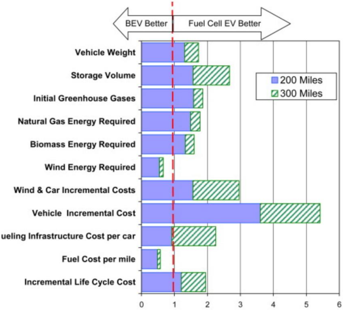
2.2. Comparison between Fuel Cells and Batteries

Fuel cells are suitable for powering vehicles taking into account the ratio of useful energy per unit mass, by comparison with battery systems. Fuel cell systems are lighter than battery systems of the same power capacity, meaning that a fuel cell electric vehicle (FCEV) is lighter than an equivalent battery electric vehicle (BEV). Thus, a FCEV achieves lower specific energy consumption and longer autonomy range compared with a BEV of same weight. At the same time, FCEV presents a positive effect on the volume required to store the system in the vehicle considering the autonomy range. An electric vehicle (EV) with an advanced Li-ion battery could in principle achieve a 400–480 km range, but these batteries would take up 450–600 L of space [47] while a fuel cell plus hydrogen storage tanks would take up approximately half that space.
Moreover, greenhouse gas emissions (GHG) for FCEV can be lower than a BEV since batteries are more substantial than fuel cell system for a given range and fuel consumption will be more significant. In determining the type of vehicle that produces less GHGs, its fundamental source of power is very crucial. For example, extracting hydrogen from natural gas by steam reforming is more efficient than producing electricity from the same source [47]. Best results to cut GHGs from Figure 4 below can be achieved by generating electricity from wind turbines, but the energy efficiency of extracting hydrogen using this source is lower since it requires an additional conversion process such as electrolysis. The next section explores the performance of proton-exchange membrane fuel cells and its advancement in the automotive industry.

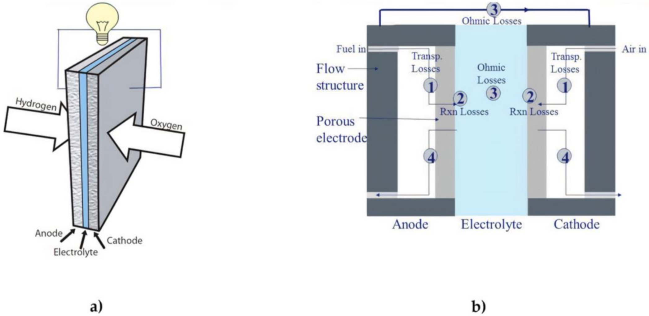
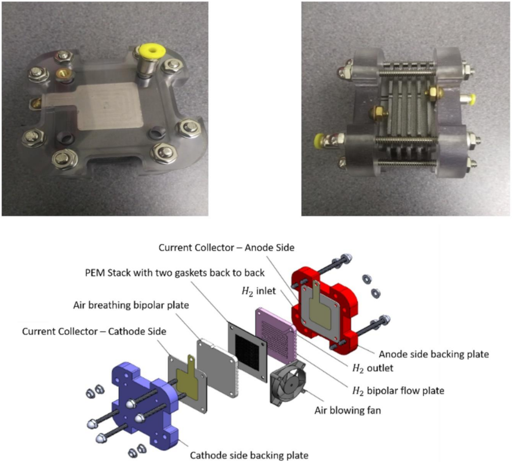
3. Proton-Exchange Membrane Fuel Cells (PEMFCs)

PEMFCs are based on hydrogen and oxygen/air reactants, composed typically by a Nafion membrane carrying positive ions H+. The polymeric membrane acts as an electrolyte. Thanks to fast start-up, high power density, lightness, compactness and low operation temperature, PEMFC are especially indicated for automotive applications [48]. It can operate at a low-temperature range between 60–80 °C (low-temperature PEMFC) or a high range between 130–200 °C (high-temperature PEMFC) depending on the electrolyte used. The advantages are fast cold start and high efficiency added to the fact that they can be easily assembled in stacks, thus giving higher power outputs. The cathode is supplied with air while the anode is filled with hydrogen. If hydrogen comes from hydrocarbon reforming, it is necessary to eliminate the presence of CO to avoid catalyst poisoning in low-temperature PEMFCs. High-temperature PEMFCs are not sensitive to CO and do not need membrane hydration, which is essential for the operation of low-temperature PEMFCs. These must be equipped with a water management system.

Composition of Proton-Exchange Membrane Fuel Cells

The structure of proton-exchange membrane fuel cells is made up of anode and cathode electrodes, proton exchange membrane, catalyst layer, gas diffusion layer and bipolar plates. The cell has a specular structure subdivided by the membrane through which there is the passage of ions between the electrodes, as shown in Figure 5. The reactant gases, subjected to electrochemical reactions in the cell, flow through the delivery manifolds into the anode and the cathode. The oxidation and reduction reactions take place at the interface between the electrode and the membrane where the catalyst particles are present. The gas diffusion layer ensures that the gas moves towards the catalyst layer and that electrons flow to and from the catalyst.
To increase the power extracted from a fuel cell, the cells in the stack can be connected in series with the aid of the bipolar plates (Figure 5). A PEMFC requires good humidification of the membrane, and the heat produced as by-product needs to be expunged to prevent an excessive temperature increase that causes membrane dehydration. The membrane can be humidified by self-humidification; thus, it uses the same water produced by the reaction, or a humidifier sprays water vapour into hydrogen and air streams to regulate their relative humidity. An air or water cooling system can be used to reduce the operating temperature.
Membranes play a crucial role in PEMFCs, and have two different functions: carry the protons, and serve as a barrier to prevent the reactive substances from mixing up. Particularly, polymeric membranes must possess the following properties to ensure high PEMFC efficiency: high proton conductivity to dispose of high currents with minimal resistive losses, zero or very small electronic conductivity, lower electrical resistance and mechanical, chemical and electrochemical stability in operating conditions [50]. Other requirements are oxidative and hydrolytic stability, ability to remain hydrated, adequate price, low fuel permeability and low coefficient of electro-osmotic resistance [50]. Currently, the premiere commercial PEMs used in the fuel cells are made of Nafion.
Nafion membranes are required to be operated at low temperatures (below 80 °C) and need to be highly hydrated to ensure the best electrochemical properties. Low humidity and high temperatures decrease the proton conductivity [47]. Therefore, low-temperature PEMFCs need careful management of heat and water as well as suffering from CO catalyst poisoning and fuel dispersion in the membrane. Membranes that do not need hydration are under development and, operating at high temperatures, they improve catalyst efficiency, accelerate the catalytic activity, decrease the susceptibility to impurities to the anodic catalyst and simplify thermal regulation [43]. Furthermore, a cost reduction is expected because, thanks to the higher catalytic action at high temperatures, the platinum load is reduced [41,43].
The electrodes play a fundamental role in the function of the fuel cell. There is transport of gas, water, ions and electrons in the electrodes and, in the points where those species meet with the catalyst, they must reduce oxygen or oxidise hydrogen to the cathode and anode, respectively. The electrodes must be porous, electronically and ionically conductive and have a large surface area. Researchers are developing new electrodes, in particular, intending to reduce the platinum load due to its high cost and the limited supplies available. This can be done in two ways: develop platinum electrodes with lower Pt content (by enhancing the use of Pt from increasing the active Pt sites, thinning the thickness of the active layer and introducing smaller Pt nanoparticles on the carbon support) or with partial or total Pt replacement by other non-precious metals [47]. A valid alternative is represented by palladium which has physical properties similar to Pt but with the great advantage of costing three times less and being 50 times more abundant on Earth [48,49].
Bipolar plates play a crucial role in PEMFCs [48,49,50]. They evenly distribute hydrogen and air, carry current from the cell, remove heat and prevent the loss of reactant gases and coolant. In addition, they contribute significantly to the volume, weight and cost of the stack, the reason why there are significant efforts all over the world to search for suitable materials. The bipolar plates used on PEMFCs aimed at transport applications must have the following characteristics: corrosion resistance (<1 µAcm−2), electrical conductivity (>100 Scm−1), flexural strength (ASTM D790-10)(>25 MPa), H2 permeation rate (<1.3 × 10⁻¹⁴ (cm3(cm2s)−1)), area specific resistance (0.01 Ω-cm2) and weight (<0.4 KgKW−1).
This review explores the latest technological advancement in proton-exchange membrane fuel cell for hybrid electric vehicle application. The next sections delve into the application of PEMFC in the automotive industry. The latest research directions in this field are critically analysed and the future perspective of the hydrogen economy equally ascertained.

4. Prospects of Fuel Cell in the Automotive Industry

For decades, internal combustions engines (ICE) dominates as the main propulsion equipment in the automotive industry. In the transportation sector, most engines use fossil fuels [58]. Many countries around the world are setting emission reduction targets. The amount of fossil fuel that EU imports are worth around £215 billion every year, or approximately £603 million a day. This amount of money is about the same bailouts to Portugal, Greece and Ireland annually. Vehicles using fossil fuel in the transport sector are globally above 90% [59].
All the efforts to make new conventional cars less pollutant will not solve the high level of GHG emissions. According to a recent study, the transport sector is emitting around 7000 Mt CO2 annually into the atmosphere, making it the second largest pollutant of GHG emissions [60]. One of the measurements the UK implemented to tackle the emissions problems in the transport sector is the ultra-low emission automobiles acquired strategies, funded through the Office for Low Emission Vehicles [61].
Back in 2008, hydrogen fuel cell vehicles were mentioned by the U.S. National Research Council as the best alternative to fulfil the GHG emissions reduction target [62]. UKH2 Mobility is a private-public partnership established by the UK government back in 2012 with the aim of evolving HFCHVs in the UK, starting from 2015. To overcome many of these complications, PEMFCHV can become one of the solutions to the transport sector in the EU and around the world. PEMFC technology has been dominating the automotive industry so far due to its numerous advantages compared with other types of FCs [63]. The need of shorter start-up times, recurrent starts and stops, and process at low and high temperature are among the main reasons for PEMFC to be favoured [41].
PEMFCHVs are expected to be cost-competitive with modern ICE automobiles in the near future. PEMFCHVs have higher efficiency, which qualifies them to fewer GHG emissions per km in comparison with ICE cars. In addition to that, PEMFCHVs have zero exhaust emission and they can be utilised as moveable electrical power source. Moreover, PEMFCHVs have the ability of quick refuelling just like ICE cars and drive more than 500 km with a full hydrogen tank. Although the hydrogen infrastructure is not yet at a satisfactory level, many companies have already started commercialising PEMFCHVs, such as Toyota and Hyundai, while others like Honda and Daimler may follow soon.

4.1. Some Applications of Fuel Cells in the Automotive Industry

Wheelchairs, scooters, motorbikes and golf carts are examples of light traction vehicles powered using proton-exchange membrane fuel cells. Pallets and forklifts can also be powered by fuel cells. A research conducted on the application of fuel cells on forklifts generated good results [64,65]. The outcome of the investigation will have a direct implication on the warehouse industry, as there are presently more than three million forklifts operational in North America alone. These forklifts were initially powered using lead-acid batteries or sometimes spark-ignition engines operated by gasoline, liquefied petroleum or even propane. The main issue of battery-powered forklifts was the long charging time of the battery. On the other hand, the fuel cell could simply be fully charged within 2–6 min.
The fuel cell forklifts can function continuously for long periods, but the battery ones normally require charging after eight continuous hours of operation [65]. The sensitivity of batteries is also very high in comparison to fuel cells. The battery components are equally susceptible to degradation even when it is not operational, unlike that of the fuel cells. Disposal of batteries after its life cycle is another major downside of this energy storage device as option for stationary and portable applications, in comparison with fuel cells. The integration of fuel cells on forklifts requires the installation of liquid hydrogen/fuel feeding systems with the aid of on-board hydrogen reformation or generation systems. This system tends to increase the bulky nature of the entire system hence it is required to consider a refuelling station instead of an on-board hydrogen generation system.

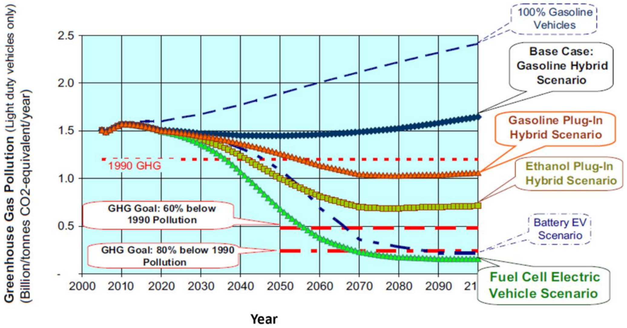
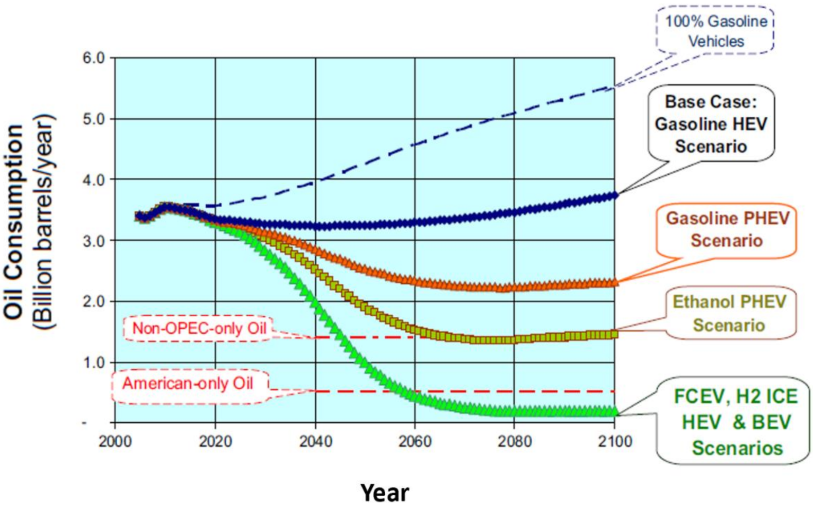
4.2. Light Duty Fuel Cell Electric Vehicles

The propulsion of these types of vehicles is dependent on the performance of the fuel cell integrated on them. The level of noise produced by these vehicles is far lower, compared to those vehicles powered by gasoline. Energy is judiciously utilised in fuel cells, as they have reported 30% higher well-to-wheel efficiency compared to internal combustion engines. Light duty fuel cell electric vehicles offer a longer range of operation and lower refuelling time. Light-duty fuel cell vehicles are able to withstand cold conditions coupled with their weight being far lighter compared to ICE vehicles [66,67,68,69,70].
The main challenges impeding the commercialisation of the technology are the lifecycle cost and durability of the entire system [70]. System modularity is another primary factor that significantly determines the future commercialisation of the technology. The fuel cells must be designed to be able to sustain the start-stop cycles [71]. The bipolar plate weight, hydrogen storage, thermal and water management must all be investigated properly to solve these current challenges [72].
The characteristics of PEMFCs having quick start up time as well as good operating temperature range makes them ideal for light vehicles. Many automotive companies, like General Motors, Toyota, Mazda, Volvo, Volkswagen, Nissan, Hyundai and others, are conducting investigations to accelerate the commercialisation of FCEVs. Hyundai, in 2013, developed the first light fuel cell electric vehicle named ix35. Hyundai supplied Denmark and Sweden with 17 light FCEVs in 2013, but currently have many ix35 models at a single cost of $50,000 [73,74]. Figure 6 captures the various components in light fuel cell electric vehicles. The main powertrain components of light FCEVs are fuel (hydrogen) storage tank, air compressor, fuel cell, cooling systems, electric motor, transmission systems, power control units and batteries, and may also include regenerative braking system [75,76]. Power conditioning electronics and other components are also needed. Currently, light nickel-metal hydride battery is dominating the electric vehicle market [77].
Like anything else, light FCEVs and light BEVs both have their advantages and disadvantages. The limitations of the two can span from the primary sources of energy, processes leading to energy being converted as well as design requirement. It has been proven that the application of both batteries and fuel cells on EVs is environmentally friendly compared to other energy generation medium for automotive purposes. This phenomenon is due to even distribution of power between the fuel cell and the battery [78,79]. One of them can be designed to supply average power to the automobile while the other supply power during fluctuations when the car is accelerating. This tends to increase the lifespan of the fuel cell and help prevent the process of designing bigger fuel cells to meet such demands.
For driving range more than 160 km, using a light FCEV would be a better option compared to a light BEV [78,79,80]. The main factors considered during the investigation were the amount of GHGs and the well-to-wheel energy efficiency. The total emissions from cars that are operated using hydrogen fuel cell or ethanol tend to show lower GHGs compared to other technologies. The fuel needed for the operation of light fuel cell electric vehicle is normally produced off-board [81]. Producing hydrogen on board can be done, but it comes with many challenges. Today, the research community in fuel cells are conducting many investigations in hydrogen storage considering compressed hydrogen, liquid hydrogen, metal hydrides, etc. These storage systems are required to meet certain specific criteria in order to make them safe [82].

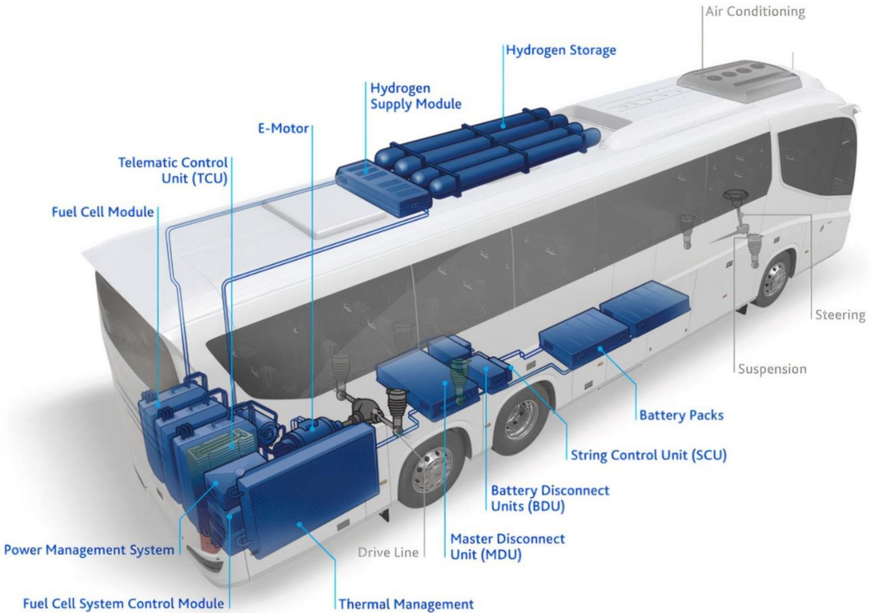
4.3. Heavy Duty Fuel Cell Electric Vehicle

Fuel cells can also be integrated on buses, heavy duty trucks, vans and utility trucks. In the last two decades, Europe has seen several fuel cell buses being developed. The research community today are championing many research activities in the fuel cell transportation industry. Using fuel cells in buses can help to reduce emissions into the atmosphere, especially in times when people in urban cities are being encouraged to use public transportation to reduce congestion [81]. Fuel cell powered buses provide lower emissions compared to conventional ICE powered buses. Their efficiency is also high compared to traditional diesel-based buses. In addition, they operate silently, hence making them ideal in public space.
The complexity of the hydrogen infrastructure for buses tends to be lower compared to fuel cell electric vehicles [82]. This can be attributed to buses plying known routes hence the hydrogen infrastructure becoming less cumbersome. Many governmental projects are being rolled out in Europe to support the development of fuel cell electric buses in South America, Japan, China, etc. The largest fuel cell electric buses programmes for demonstration was carried out in Australia, the Sustainable Transport Energy Programme, and Europe, the Clean Urban Transport [83]. Other projects like the hydrogen fuel cell demonstration project, the urban route buses trial project in China, and the California Zero Emission Bay area project attest to the progress being made globally on fuel cell electric buses [84,85,86]. Figure 7 shows the various components in a fuel cell electric bus.

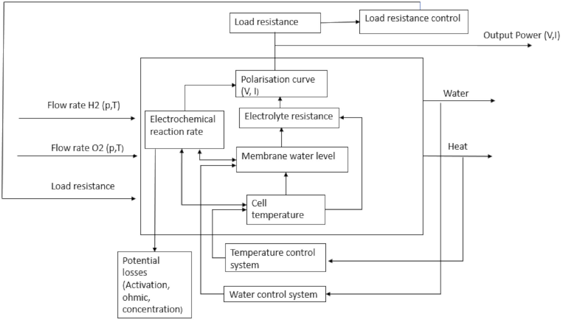
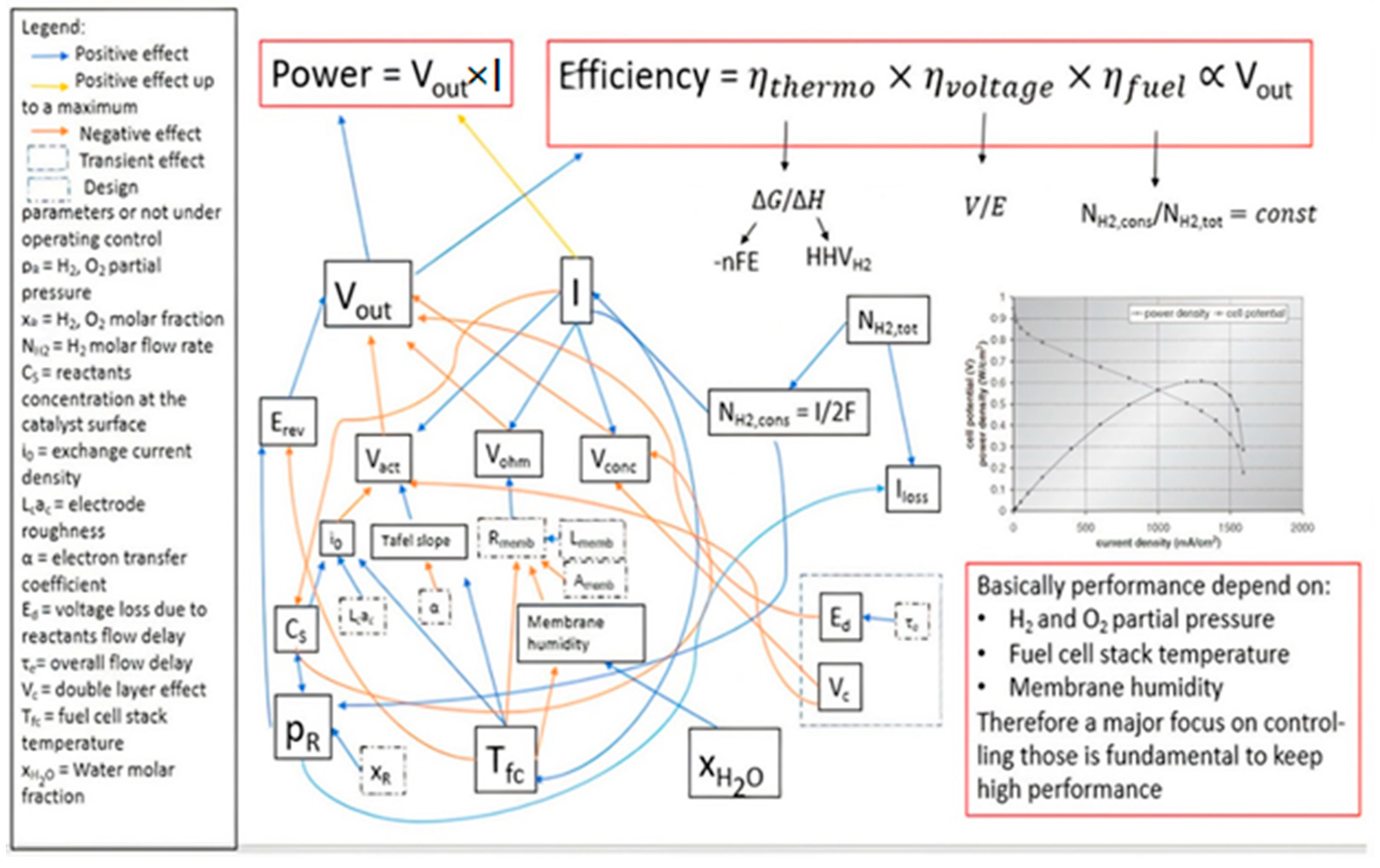
5. Fuel Cell Optimization Criteria

The literature indicates that the fuel cell performance largely contributes to the overall cost of a FCEV. Therefore, this section explores methods that can be adopted to ensure efficient and high fuel cell performance to reduce the overall cost of the technology in any specific application.

5.1. Operating Parameters of Fuel Cell

From observing the equations that govern the performance of a fuel cell, it is noticeable that a series of parameters govern its performance; therefore, the fuel cell optimisation requires the control of these parameters. The parameters that influence the performance of a fuel cell can be distinguished in two types, as reported in Table 4. The parameters that can be controlled are those of most considerable interest since they allow directly adjustment to decide the desired operating point. However, choosing which parameters to act on and how is not a trivial solution. Since the parameters often have reciprocal relationships, it is not easy to predict how the variation of one can be reflected in the overall performance of the system. For example, from the diagram of Figure 8, the operating point of a fuel cell is determined by the combination of the polarisation curve and the load resistance. Given the polarization curve depends on the voltage and current, which in their turn depend on the load condition, the only independent parameter to be controlled is the external load resistance.
From Figure 9, it can be deduced that there is a dense network of relationships determining the potential and the current supplied by the fuel cell, and these relations do not have linear characteristics to define the power and efficiency of the system. For example, one can see how the voltage plays a fundamental role in increasing both the power and the efficiency, but the same depends on the current required by the load. High load tends to lower the voltage due to the increase in the activation, ohmic and concentration losses. In turn, these losses will be influenced by a series of factors that have been identified in the related equations, which in the end respond to three parameters namely:
  • Partial pressure of the reactants (hydrogen and oxygen, for a PEMFC)
  • Stack temperature
  • Membrane humidity
By managing these parameters the performance of a fuel cell can be controlled, so the range in which these parameters must be maintained is of fundamental importance not only to satisfy the demand for load power but also to optimise the efficiency and useful life of the system.

5.2. Techniques to Adopt to Improve Fuel Cell Performance

Given the central role of the cell voltage in determining power and efficiency, interventions to optimise performances aim to maximise the voltage. Therefore, to optimise the cell voltage, the irreversible losses must be minimised. For example, to reduce the activation losses that occur due to the energy barriers that hinder the kinetics of reaction to the electrodes, the following steps can be adopted [89]:
  • Increase the cell temperature
  • Use a catalyst that improves the reaction kinetics
  • Increase the electrode roughness to increase the catalyst surface on the electrode and thus increase the reaction sites
  • Increase the concentration of reagents as the density of the current exchange increases
  • Increase reagent pressure as it increases concentration.
To minimize the losses due to the crossing of the electric charges in the conductor materials of ions and electrons, the electrical resistance of these materials have to be minimised in the following ways [67]:
  • Use electrodes with the highest conductivity
  • Optimisation of design and choice of materials for bipolar plates
  • Make the membrane as thin as possible
  • Increase the membrane humidity.
To limit the negative effects on the voltage during the increase of the current density that lowers the concentration of reactant on the reaction sites, the following parameters can be improved [67]:
  • The speed with which the reagent gases are supplied
  • The geometry of the reagent delivery channels
  • The diffusive characteristics of gas diffusion layers and electrodes
  • The air circulation in the cathode to avoid the accumulation of water produced by the reaction.
However, it is necessary to operate with sufficient knowledge of the facts and to have an overall vision of the system when a variation of the operating parameters is used since the improvement of some aspects can lead to the worsening of others. Without a weighted compromise, a performance degradation and even a decrease in the useful life of fuel cell could occur. For example, increasing the temperature or the pressure of oxygen leads to reducing the activation losses by increasing the current density and, therefore, the power supplied [90]. Similarly, when increasing the temperature, care must be taken because it can lead to dehydration of the membrane, which is fundamental for maintaining good ionic conductivity. Even the increase in oxygen pressure must be done with criteria so that the pressure difference between the cathode and the anode is not harmful to the membrane.
Increasing the pressure of the reagents reduces concentration losses and improves the diffusion of gases in the electrodes, which means a potential gain but at the same time the requirement of thicker membranes to withstand higher mechanical stresses that leads to an increase in ionic resistivity.
Using pure oxygen instead of air increases the partial pressure and the oxygen diffusion rate, generating higher potential values and up to 32% more power than using air [91]. This improves oxygen partial pressure in air, but, at the same time, it requires a system more suitable in terms of safety and maintenance. In fuel cells that humidify the membrane using the same water produced by the reaction (self-humidified), the flow rate of hydrogen and air has a great impact on performance due to the risk of membrane dehydration, especially at low current densities, since the produced water is decreased. The increase in the airflow rate leads to higher power output, but, at the same time, the air carry away more water produced at the cathode limiting the amount that can be used to humidify the membrane, so it is very important to find a compromise in the airflow that can increase performance while maintaining the right level of membrane hydration [92].
A study by Chan et al. [93] showed that the factor most influencing the performance of the fuel cell is the limitation of mass transport. This includes the transportation of reagents inside the electrodes to the active sites of the catalyst, the transport of hydrogen ions from the anode to the cathode through the membrane, and the reverse diffusion of the water produced by the reaction from the cathode to the anode. The fuel cell performance was evaluated by varying the operating parameters such as the anode and cathode operating pressure, cell temperature, and the humidification effect at the anode and cathode. The effect of high temperature is positive for humidified gases, while, for dry gases, higher temperatures increase the cell performance only for high current densities. On the other hand, lower temperatures give better performance for low current densities.
Although higher temperatures lead to an increase in the diffusivity of the gases and improve the ionic conduction of the membrane, on the other hand, they also lead to greater evaporation of water and, therefore, drying of the membrane, which loses its conductivity [93]. With humidified gases, water vapour present in the reactant gases balances the drying effect of temperature. However, with non-humidified gases, water produced by the reaction humidifies the membrane. The water amount at low current density is lower than the amount produced at high current density. Therefore, higher temperatures lead to extensive membrane drying.
Increasing pressure brings benefits to performance as this increases the diffusivity of the reactant gases, facilitating the mass transport to the electrodes [93]. In the tests in which the effects of pressure on only one of the electrodes were evaluated, it was observed how the impact of pressure is more critical when the cathode is pressurised. This effect can be explained because the water produced by the reaction at the cathode diffuses into the membrane by the pressure gradient towards the anode, especially at high current densities, thus humidifying the membrane and solving the problem of water accumulation in the cathode that hinders the filling by new oxygen.
Humidifying both flows of reacting gases gives the most positive effects due to better membrane humidification [93]. The impact of the hydrogen humidification is more significant impact than the previous ones, since the conduction of hydrogen ions in the membrane is favoured. Water balancing between the anode and the cathode is fundamental since the water content not only greatly influences the membrane conductivity, but it is also vital for the transport of the reagents and the reaction kinetics in the electrodes. While very low amounts of water lead to a decrease in membrane conductivity, excessively large amounts of water can lead to flooding of the cathode and make more difficult the replacement of new oxygen with the consequent slowing of the reactions. Therefore, it is necessary to find an optimal between the relative humidity and temperature to have good membrane humidification and, at the same time, evacuate sufficient water to the cathode.
For example, Bernardi and Verbrugge [94] have developed a mathematical model to determine the operating conditions that allow an optimal balance of water between that formed during the reactions and that which must be disposed of to avoid flooding. Yi and Nguyen [95] developed a model along the channel for evaluating the effects of various operational and design parameters on the performance of a PEM fuel cell. Their results showed that the performance of a PEM fuel cell could be improved with anode humidification and a positive pressure gradient between the cathode and the anode to increase the water back flow diffused from the cathode into the membrane. Nguyen and White [96] developed a model of water and heat management for fuel cells and used the model to study the effectiveness of various humidification levels. The authors [96] found that, at high current density (>1 Acm−1), the ohmic loss in the membrane is responsible for a significant fraction of the cell voltage loss and the diffusion of water between the cathode and membrane is insufficient to keep the membrane hydrated. Consequently, to minimise ohmic losses, the hydrogen flow must be humidified, and so must the cathode when air is used instead of oxygen [97]. On the other hand, it has also been shown the possibility to operate a fuel cell with non-humidified gases while maintaining excellent performance when the cell temperature, the flow stoichiometry at the anode and the cathode, and the pressure difference between anode and cathode is optimized. This would be possible using the water produced at the cathode to keep the anode humidified up to the temperature of 70 °C, at atmospheric pressure.
A study by Williams et al. [98] showed that it is possible to have smaller performance losses by operating with a dry cathode and anode flow in saturated conditions. If the gases in the anode and cathode are both dry, the cell temperature and the gas stoichiometry have a decisive influence on cell performance. Too high temperatures cause the membrane drying, lowering its proton conductivity, while too low temperatures can cause cathode flooding, preventing the oxygen from taking part in the reactions. Too high stoichiometry causes a drying of the membrane, while too low stoichiometry leads to low partial pressure that causes mass transport losses. The optimal conditions varying the cell temperature and the cathode stoichiometry were obtained by increasing the temperature while the stoichiometry was lowered, maintaining a constant stoichiometry at the anode and the relative humidity of the membrane at 60%. Comparing the entire system performance of a stack operating without humidification with another stack operating with gas in saturated conditions, the stack with dry gases has the advantage of being much simpler due to the lack of humidifiers and condensers but the net power is decreased by 17%. Operation at low current densities increases the efficiency of a stack functioning with dry gases, but this requires increased stack size to maintain the same output power with a consequent increase in cost. Additionally, a series of complications and precautions must be considered to allow optimal performance with dry gases operation, including the use of suitable gas diffusion layer and a different design for the flow field plates, making the use of humidified gases more reasonable.

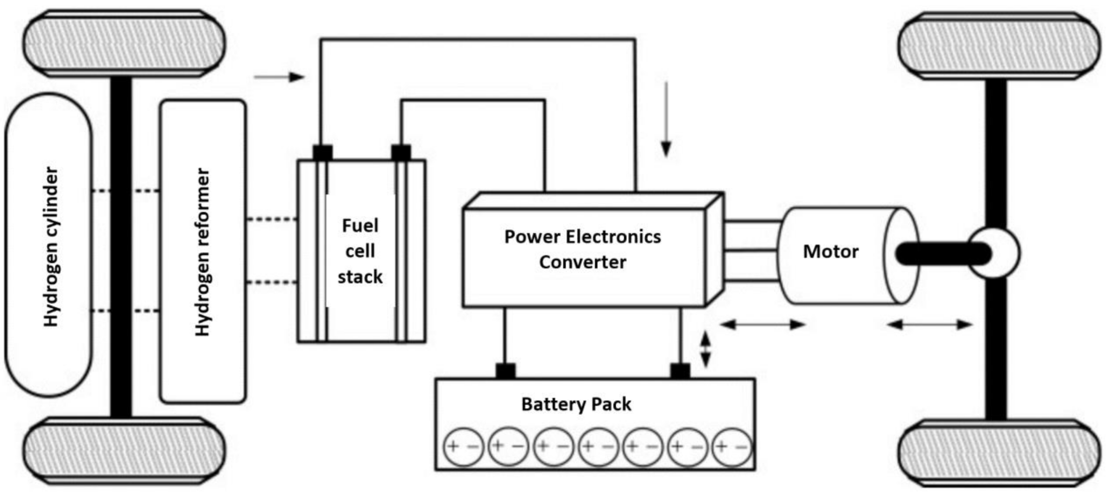
5.3. Fuel Cell Hybrid System

A fuel cell has slow response times to load variations because, when the required current varies, a series of parameters must change within the fuel cell, such as pressure and concentration of the reagents, temperature, membrane humidity, etc., which require a longer time to stabilise than the load variation. However, when the demand for current varies abruptly, the reactions that occur to the catalyst have a much higher rate than the change of the frequency with which the reagents are supplied to the electrodes. This can lead to the phenomenon known as reactant starvation, causing not only a significant decrease in the generated power but also membrane destruction. This severe predisposition of the fuel cell to react to transitory demand requires, in most cases, boosting with batteries and super-capacitors to provide rapid answers during the rapid changes of absorbed power, thus avoiding a lowering of the power supplied by the fuel cell and giving protection from reactant starvation.
Power transients are quite considerable during the system start-up and shutdown phase, so the use of a battery that can handle these sudden power changes is necessary, especially for applications where power often varies over time as in the field of transportation or distributed generation. The behaviour of a fuel cell for a distributed generation application in a hybrid system with the aid of a battery that supports the power delivered by the system during sudden power transients in order to preserve the fuel cell from excessive drops in performance that could lead to reactant starvation has been studied [76]. The hybrid system consisted of a fuel cell with a nominal power of 1.2 kW, equal to the average power required by the network, which could reach peaks of 2.4 kW. A lithium battery with a capacity of 5 Wh completed the hybrid system, guaranteeing power for the remaining 1.2 kW that could not be supplied by the fuel cell. When the system operated at stationary conditions, the battery did not intervene and was recharged by the fuel cell.
The system was made to operate in two cases: the fuel cell is left to respond naturally to the variation of the requested power, or a DC/DC limiter is used to allow the fuel cell to reach the steady-state flow conditions and reagent pressure gradually [99]. In the first case, the battery responds instantly during the 1.2 kW power jump required by the grid, allowing the fuel cell to align itself with this power with a delay of about 100 ms. In the second case, a current limiter is used, which sets a linear rate of change of 20 A/s. This permits fuel alignment to the more gradual power required by the network, which is compensated by a supply of battery power for a longer time than in the first case, also allowing a softer descent of the voltage. This is undoubtedly positive for the performance of the fuel cell, which is preserved by reactant starvation and, consequently, collapse in performance and cell useful lifetime.

6. Conclusions

Some of the notable advantages of fuel cells are their modularity, quick start-up, high efficiency, no noise production due to the absence of moving parts, and the production of water as the only by-product of the electrochemical reactions, making them environmentally friendly. These facts are salient reasons for the appreciable increase of fuel cell applications in the last decade. The integration of fuel cells to the automotive industry is gradually expanding due to the associated advantages but, despite the progress made, fuel cells still have a long way to go into becoming largely commercialised. Key factors impeding their advancement are their high costs and material degradation. A reduction in fuel cell operating cost can also be possible via material characterisation and optimisation of operating parameters. Key research gaps that must be considered in future investigations include membrane delineation and reduction or replacement of platinum catalyst by a cheaper but equally efficient material. Membrane thickness, bipolar plate geometry design, current collector material and material weight significantly affect the overall cost of a running cell. A well-documented risk assessment should be an active research direction, and public sensitization in terms of safety and advantages of the technology can immensely accelerate fuel cell deployment.

Author Contributions

Conceptualization, T.W., A.A., A.B., A.O., J.R.S., and methodology, A.A., A.O. and T.W.; formal analysis, M.D., T.W., J.R.S., A.A.; investigation, A.O., T.W.; resources, T.W., J.R.S., A.A.; data curation, T.W., J.R.S.; writing—original draft preparation, T.W., A.A., J.R.S.; writing—review and editing, T.W., A.A., J.R.S.; supervision, J.R.S., A.O., A.A.; project administration, A.G.O., T.W., G.P., M.D. All authors have read and agreed to the published version of the manuscript.

Funding

This research received no external funding.

Conflicts of Interest

The authors declare no conflict of interest.

References

  1. Wilberforce, T.; Sayed, E.T.; Abdelkareem, M.A.; Elsaid, K.; Olabi, A. Value added products from wastewater using bioelectrochemical systems: Current trends and perspectives. J. Water Process. Eng. 2020, 101737. [Google Scholar] [CrossRef]
  2. Baroutaji, A.; Arjunan, A.; Alaswad, A.; Praveen, A.S.; Wilberforce, T.; Abdelkareem, M.A.; Olabi, A.-G. Materials for Fuel Cell Membranes. Ref. Module Mater. Sci. Mater. Eng. 2020. [Google Scholar] [CrossRef]
  3. Olabi, A.; Abdelkareem, M.A.; Wilberforce, T.; Sayed, E.T. Application of graphene in energy storage device—A review. Renew. Sustain. Energy Rev. 2021, 135, 110026. [Google Scholar] [CrossRef]
  4. Ogungbemi, E.; Wilberforce, T.; Ijaodola, O.; Thompson, J.; Olabi, A. Selection of proton exchange membrane fuel cell for transportation. Int. J. Hydrogen Energy 2020. [Google Scholar] [CrossRef]
  5. Abdelkareem, M.A.; Lootah, M.A.; Sayed, E.T.; Wilberforce, T.; Alawadhi, H.; Yousef, B.A.; Olabi, A.G. Fuel Cells for Carbon Capture Applications. Sci. Total Environ. 2020, 144243. [Google Scholar] [CrossRef]
  6. Ogungbemi, E.; Wilberforce, T.; Ijaodola, O.; Thompson, J.; Olabi, A. Review of operating condition, design parameters and material properties for proton exchange membrane fuel cells. Int. J. Energy Res. 2020. [Google Scholar] [CrossRef]
  7. Rabaia, M.K.H.; Abdelkareem, M.A.; Sayed, E.T.; Elsaid, K.; Chae, K.J.; Wilberforce, T.; Olabi, A. Environmental impacts of solar energy systems: A review. Sci. Total Environ. 2021, 754, 141989. [Google Scholar] [CrossRef] [PubMed]
  8. Elsaid, K.; Olabi, A.; Wilberforce, T.; Abdelkareem, M.A.; Sayed, E.T. Environmental Impacts of Nanofluids: A Review. Sci. Total Environ. 2020, 144202. [Google Scholar] [CrossRef]
  9. Abdelkareem, M.A.; Wilberforce, T.; Elsaid, K.; Sayed, E.T.; AbdelGhani, E.A.; Olabi, A. Transition metal carbides and nitrides as oxygen reduction reaction catalyst or catalyst support in proton exchange membrane fuel cells (PEMFCs). Int. J. Hydrogen Energy 2020. [Google Scholar] [CrossRef]
  10. Olabi, A.; Wilberforce, T.; Abdelkareem, M.A. Fuel cell application in the automotive industry and future perspective. Energy 2021, 214, 118955. [Google Scholar] [CrossRef]
  11. Olabi, A.; Onumaegbu, C.; Wilberforce, T.; Ramadan, M.; Abdelkareem, M.A.; Al-Alami, A.H. Critical review of energy storage systems. Energy 2021, 214, 118987. [Google Scholar] [CrossRef]
  12. Sayed, E.T.; Wilberforce, T.; Elsaid, K.; Rabaia MK, H.; Abdelkareem, M.A.; Chae, K.J.; Olabi, A.G. A critical review on Environmental Impacts of Renewable Energy Systems and Mitigation Strategies: Wind, Hydro, Biomass and Geothermal. Sci. Total Environ. 2020, 144505. [Google Scholar] [CrossRef]
  13. Elsaid, K.; Olabi, A.; Wilberforce, T.; Abdelkareem, M.A.; Sayed, E.T. DeNOx removal techniques for automotive applications—A review. Environ. Adv. 2020, 2, 100021. [Google Scholar] [CrossRef]
  14. Wilberforce, T.; Ijaodola, O.; Khatib, F.; Ogungbemi, E.; El Hassan, Z.; Thompson, J.; Olabi, A. Effect of humidification of reactive gases on the performance of a proton exchange membrane fuel cell. Sci. Total Environ. 2019, 688, 1016–1035. [Google Scholar] [CrossRef] [PubMed]
  15. Wilberforce, T.; El Hassan, Z.; Ogungbemi, E.; Ijaodola, O.; Khatib, F.; Durrant, A.; Thompson, J.; Baroutaji, A.; Olabi, A. A comprehensive study of the effect of bipolar plate (BP) geometry design on the performance of proton exchange membrane (PEM) fuel cells. Renew. Sustain. Energy Rev. 2019, 111, 236–260. [Google Scholar] [CrossRef]
  16. Wilberforce, T.; Ijaodola, O.; Ogungbemi, E.; Khatib, F.; Leslie, T.; El-Hassan, Z.; Thomposon, J.; Olabi, A. Technical evaluation of proton exchange membrane (PEM) fuel cell performance—A review of the effects of bipolar plates coating. Renew. Sustain. Energy Rev. 2019, 113. [Google Scholar] [CrossRef]
  17. Alawadhi, H.; Abdelkareem, M.A.; Hussain, N.; Wilberforce, T.; Sayed, E.T. A composite of graphitic carbon nitride and Vulcan carbon as an effective catalyst support for Ni in direct urea fuel cells. J. Taiwan Inst. Chem. Eng. 2020. [Google Scholar] [CrossRef]
  18. Elsaid, K.; Kamil, M.; Sayed, E.T.; Abdelkareem, M.A.; Wilberforce, T.; Olabi, A. Environmental impact of desalination technologies: A review. Sci. Total Environ. 2020, 748, 141528. [Google Scholar] [CrossRef]
  19. Al-Anazi, A.; Wilberforce, T.; Khatib, F.; Vichare, P.; Olabi, A. Performance evaluation of an air breathing polymer electrolyte membrane (PEM) fuel cell in harsh environments—A case study under Saudi Arabia’s ambient condition. Int. J. Hydrogen Energy 2020. [Google Scholar] [CrossRef]
  20. Wilberforce, T.; Olabi, A.; Sayed, E.T.; Elsaid, K.; Abdelkareem, M.A. Progress in carbon capture technologies. Sci. Total Environ. 2020, 143203. [Google Scholar] [CrossRef]
  21. Olabi, A.; Wilberforce, T.; Ramadan, M.; Abdelkareem, M.A.; Alami, A.H. Compressed air energy storage systems: Components and operating parameters—A review. J. Energy Storage 2020, 102000. [Google Scholar] [CrossRef]
  22. Khatib, F.; Wilberforce, T.; Thompson, J.; Olabi, A. A comparison on the dynamical performance of a proton exchange membrane fuel cell (PEMFC) with traditional serpentine and an open pore cellular foam material flow channel. Int. J. Hydrogen Energy 2020. [Google Scholar] [CrossRef]
  23. Abdelkareem, M.A.; Elsaid, K.; Wilberforce, T.; Kamil, M.; Sayed, E.T.; Olabi, A. Environmental aspects of fuel cells: A review. Sci. Total Environ. 2021, 752, 141803. [Google Scholar] [CrossRef] [PubMed]
  24. Olabi, A.; Mahmoud, M.; Soudan, B.; Wilberforce, T.; Ramadan, M. Geothermal based hybrid energy systems, toward eco-friendly energy approaches. Renew. Energy 2020, 147, 2003–2012. [Google Scholar] [CrossRef]
  25. Wilberforce, T.; Baroutaji, A.; El Hassan, Z.; Thompson, J.; Soudan, B.; Olabi, A. Prospects and challenges of concentrated solar photovoltaics and enhanced geothermal energy technologies. Sci. Total Environ. 2019, 659, 851–861. [Google Scholar] [CrossRef] [Green Version]
  26. Wilberforce, T.; El Hassan, Z.; Durrant, A.; Thompson, J.; Soudan, B.; Olabi, A. Overview of ocean power technology. Energy 2019, 175, 165–181. [Google Scholar] [CrossRef] [Green Version]
  27. Wilberforce, T.; Baroutaji, A.; Soudan, B.; Al-Alami, A.H.; Olabi, A. Outlook of carbon capture technology and challenges. Sci. Total Environ. 2019, 657, 56–72. [Google Scholar] [CrossRef] [Green Version]
  28. Ijaodola, O.; Hassan, Z.E.-; Ogungbemi, E.; Khatib, F.; Wilberforce, T.; Thompson, J.; Olabi, A. Energy efficiency improvements by investigating the water flooding management on proton exchange membrane fuel cell (PEMFC). Energy 2019, 179, 246–267. [Google Scholar] [CrossRef]
  29. Olabi, A.; Wilberforce, T.; Sayed, E.T.; Elsaid, K.; Rezk, H.; Abdelkareem, M.A. Recent progress of graphene based nanomaterials in bioelectrochemical systems. Sci. Total Environ. 2020, 749, 141225. [Google Scholar] [CrossRef]
  30. Baroutaji, A.; Wilberforce, T.; Ramadan, M.; Olabi, A.G. Comprehensive investigation on hydrogen and fuel cell technology in the aviation and aerospace sectors. Renew. Sustain. Energy Rev. 2019, 106, 31–40. [Google Scholar] [CrossRef] [Green Version]
  31. Ijaodola, O.; Ogungbemi, E.; Khatib, F.; Wilberforce, T.; Ramadan, M.; El Hassan, Z.; Thompson, J.; Olabi, A. Evaluating the Effect of Metal Bipolar Plate Coating on the Performance of Proton Exchange Membrane Fuel Cells. Energies 2018, 11, 3203. [Google Scholar] [CrossRef] [Green Version]
  32. Ogungbemi, E.; Ijaodola, O.; Khatib, F.; Wilberforce, T.; El Hassan, Z.; Thompson, J.; Ramadan, M.; Olabi, A. Fuel cell membranes–Pros and cons. Energy 2019, 172, 155–172. [Google Scholar] [CrossRef] [Green Version]
  33. Thomas, C. Fuel cell and battery electric vehicles compared. Int. J. Hydrogen Energy 2009, 34, 6005–6020. [Google Scholar] [CrossRef] [Green Version]
  34. Alaswad, A.; Dassisti, M.; Palumbo, A.; Olabi, A.G. Fuel Cell Technologies, Applications, and State of the Art. A Reference Guide; Elsevier Ltd.: Amsterdam, The Netherlands, 2016. [Google Scholar]
  35. Wilberforce, T.; Olabi, A. Performance Prediction of Proton Exchange Membrane Fuel Cells (PEMFC) Using Adaptive Neuro Inference System (ANFIS). Sustainbility 2020, 12, 4952. [Google Scholar] [CrossRef]
  36. Wilberforce, T.; Olabi, A. Design of Experiment (DOE) Analysis of 5-Cell Stack Fuel Cell Using Three Bipolar Plate Geometry Designs. Sustainbility 2020, 12, 4488. [Google Scholar] [CrossRef]
  37. Wilberforce, T.; Alaswad, A.; Palumbo, A.; Dassisti, M.; Olabi, A. Advances in stationary and portable fuel cell applications. Int. J. Hydrogen Energy 2016, 41, 16509–16522. [Google Scholar] [CrossRef] [Green Version]
  38. Wilberforce, T.; Khatib, F.N.; Ogungbemi, E.; Olabi, A.G. Water Electrolysis Technology. Ref. Module Mater. Sci. Mater. Eng. 2018. [Google Scholar] [CrossRef]
  39. David, M.-S. A Review of Developments in Electrical Battery, Fuel Cell and Energy Recovery Systems for Railway Applications; A Report for the Scottish Association for Public Transport; Scottish Association for Public Transport: Glasgow, UK, 2019. [Google Scholar] [CrossRef]
  40. Collen, S. Designing and Building Fuel Cells; Mc Graw Hill: Pennsylvania, PA, USA, 2007; ISBN 0-07-148977-0. [Google Scholar]
  41. Wilberforce, T.; El Hassan, Z.; Khatib, F.; Al Makky, A.; Mooney, J.; Barouaji, A.; Carton, J.G.; Olabi, A.-G. Development of Bi-polar plate design of PEM fuel cell using CFD techniques. Int. J. Hydrogen Energy 2017, 42, 25663–25685. [Google Scholar] [CrossRef] [Green Version]
  42. Kirubakaran, A.; Jain, S.; Nema, R. A review on fuel cell technologies and power electronic interface. Renew. Sustain. Energy Rev. 2009, 13, 2430–2440. [Google Scholar] [CrossRef]
  43. Ali, D.M.; Salman, S. A Comprehensive Review of the Fuel Cells Technology and Hydrogen Economy. In Proceedings of the 41st International Universities Power Engineering Conference, Newcastle-upon-Tyne, UK, 6–8 September 2006; Volume 1, pp. 98–102. [Google Scholar]
  44. Ziaur, R.; Mashrur, I. Comparative Study of Different Fuel Cell Technologies. Asian J. Con. Sci. Technol. 2019, 1, 29–32. [Google Scholar] [CrossRef]
  45. Ellamla, H.R.; Staffell, I.; Bujlo, P.; Pollet, B.G.; Pasupathi, S. Current status of fuel cell based combined heat and power systems for residential sector. J. Power Sources 2015, 293, 312–328. [Google Scholar] [CrossRef]
  46. Appleby, A. Fuel cell technology: Status and future prospects. Energy 1996, 21, 521–653. [Google Scholar] [CrossRef]
  47. Wilberforce, T.; El-Hassan, Z.; Khatib, F.; Al Makky, A.; Baroutaji, A.; Carton, J.G.; Olabi, A.G. Developments of electric cars and fuel cell hydrogen electric cars. Int. J. Hydrogen Energy 2017, 42, 25695–25734. [Google Scholar] [CrossRef] [Green Version]
  48. Wilberforce, T.; El-Hassan, Z.; Khatib, F.; Al Makky, A.; Baroutaji, A.; Carton, J.G.; Thompson, J.; Olabi, A.G. Modelling and simulation of Proton Exchange Membrane fuel cell with serpentine bipolar plate using MATLAB. Int. J. Hydrogen Energy 2017, 42, 25639–25662. [Google Scholar] [CrossRef] [Green Version]
  49. Khatib, F.; Wilberforce, T.; Ijaodola, O.; Ogungbemi, E.; El-Hassan, Z.; Durrant, A.; Thompson, J.; Olabi, A. Material degradation of components in polymer electrolyte membrane (PEM) electrolytic cell and mitigation mechanisms: A review. Renew. Sustain. Energy Rev. 2019, 111, 1–14. [Google Scholar] [CrossRef]
  50. Wilberforce, T.; Ijaodola, O.; Ogungbemi, E.; El Hassan, Z.; Thompson, J.; Olabi, A.G. Effect of Bipolar Plate Materials on Performance of Fuel Cells. Ref. Module Mater. Sci. Mater. Eng. 2018. [Google Scholar] [CrossRef] [Green Version]
  51. Erdinç, O.; Uzunoglu, M. Recent trends in PEM fuel cell-powered hybrid systems: Investigation of application areas, design architectures and energy management approaches. Renew. Sustain. Energy Rev. 2010, 14, 2874–2884. [Google Scholar] [CrossRef]
  52. Islam, M.; Shabani, B.; Rosengarten, G.; Andrews, J. The potential of using nanofluids in PEM fuel cell cooling systems: A review. Renew. Sustain. Energy Rev. 2015, 48, 523–539. [Google Scholar] [CrossRef]
  53. Alizadeh, E.; Rahgoshay, S.; Rahimi-Esbo, M.; Khorshidian, M.; Saadat, S. A novel cooling flow field design for polymer electrolyte membrane fuel cell stack. Int. J. Hydrogen Energy 2016, 41, 8525–8532. [Google Scholar] [CrossRef]
  54. Hossain, A.K.; Serrano, C.; Brammer, J.; Omran, A.; Ahmed, F.; Smith, D.; Davies, P.A. Combustion of fuel blends containing digestate pyrolysis oil in a multi-cylinder compression ignition engine. Fuel 2016, 171, 18–28. [Google Scholar] [CrossRef] [Green Version]
  55. Ehsani, M.; Gao, Y.; Gay, S.E.; Emadi, A. Modern Electric, Hybrid Electric, and Fuel Cell Vehicles: Fundamentals, Theory, and Design, 2nd ed.; CRC Press: Florida, FL, USA, 2004. [Google Scholar]
  56. Wang, Y.; Chen, K.S.; Mishler, J.; Cho, S.C.; Adroher, X.C. A review of polymer electrolyte membrane fuel cells: Technology, applications, and needs on fundamental research. Appl. Energy 2011, 88, 981–1007. [Google Scholar] [CrossRef] [Green Version]
  57. Javaid, Z.S.M.; Matsuura, T. Polymer membranes for fuel cells. In Polymer Membranes for Fuel Cells; Springer: New York, NY, USA, 2009; pp. 1–431. [Google Scholar]
  58. Van Vliet, O.; Brouwer, A.S.; Kuramochi, T.; Broek, M.V.D.; Faaij, A. Energy use, cost and CO2 emissions of electric cars. J. Power Sources 2011, 196, 2298–2310. [Google Scholar] [CrossRef] [Green Version]
  59. Amjad, S.; Neelakrishnan, S.; Rudramoorthy, R. Review of design considerations and technological challenges for successful development and deployment of plug-in hybrid electric vehicles. Renew. Sustain. Energy Rev. 2010, 14, 1104–1110. [Google Scholar] [CrossRef]
  60. UK Government. 2010 to 2015 Government Policy: Transport Emissions–GOV.UK. 2015. Available online: https://www.gov.uk/government/publications/2010-to-2015-government-policy-transport-emissions/2010-to-2015-government-policy-transport-emissions (accessed on 17 March 2020).
  61. Olabi, A.; Wilberforce, T.; Sayed, E.T.; Elsaid, K.; Abdelkareem, M.A. Prospects of Fuel Cell Combined Heat and Power Systems. Energies 2020, 13, 4104. [Google Scholar] [CrossRef]
  62. UKH2Mobility. UK H2Mobility|Hydrogen: Fuelling Cleaner Motoring. 2012. Available online: http://www.ukh2mobility.co.uk/ (accessed on 17 March 2020).
  63. Mokrani, Z.; Rekioua, D.; Mebarki, N.; Bacha, S. Proposed energy management strategy in electric vehicle for recovering power excess produced by fuel cells. Int. J. Hydrogen Energy 2017, 42, 19556–19575. [Google Scholar] [CrossRef]
  64. Kumar, A.; Sehgal, M. Hydrogen Fuel Cell Technology for a Sustainable Future: A Review. SAE Techn. Pap. Ser. 2018, 1, 1–11. [Google Scholar] [CrossRef]
  65. Qi, Z. Application: Transportation: Light traction: Fuel cells. In Encyclopedia of Electrochemical Power Sources; Garche, J., Ed.; Elsevier: Amsterdam, The Netherlands, 2009. [Google Scholar]
  66. Dicks, A.L. PEM fuel cells: Applications. In Comprehensive Renewable Energy; Sayigh, A., Ed.; Elsevier: Oxford, UK, 2012. [Google Scholar]
  67. Colella, W.G. Market prospects, design features, and performance of a fuel cell-powered scooter. J. Power Sources 2000, 86, 255–260. [Google Scholar] [CrossRef]
  68. Lin, B. Conceptual design and modeling of a fuel cell scooter for urban Asia. J. Power Sources 2000, 86, 202–213. [Google Scholar] [CrossRef]
  69. Hwang, J.; Wang, D.; Shih, N.; Lai, D.; Chen, C. Development of fuel-cell-powered electric bicycle. J. Power Sources 2004, 133, 223–228. [Google Scholar] [CrossRef]
  70. Hwang, J.; Wang, D.; Shih, N. Development of a light weight fuel cell vehicle. J Power Sources 2005, 141, 108–115. [Google Scholar] [CrossRef]
  71. Hochgraf, C. Application: transportation: Electric vehicles: Fuel cells. In Encyclopedia of Electrochemical Power Sources; Garche, J., Ed.; Elsevier: Amsterdam, The Netherlands, 2009. [Google Scholar]
  72. Bill Thomas. Hyundai Celebrates World’s First Assembly Line Production of Zero-Emissions Fuel Cell Vehicles. Available online: https://www.prweb.com/releases/hyundai-ix35-fuel-cell/03/prweb10475471.htm (accessed on 10 October 2020).
  73. Igbinovia, F.O.; Fandi, G.; Mahmoud, R.; Tlusty, J. A Review of Electric Vehicles Emissions and its Smart Charging Techniques Influence on Power Distribution Grid. J. Eng. Sci. Technol. Rev. 2016, 2016, 80–85. [Google Scholar] [CrossRef]
  74. Gabe, B.K. Audi Loses Faith In Batteries, Restarts Hydrogen Powertrain Development. Available online: https://carbuzz.com/news/audi-loses-faith-in-batteries-restarts-hydrogen-powertrain-development (accessed on 30 July 2020).
  75. Zorpette, G. Supercharged [ultracapacitors]. IEEESpectr 2005, 42, 32–37. [Google Scholar]
  76. Pollet, B.G.; Staffell, I.; Shang, J.L. Current status of hybrid, battery and fuel cell electric vehicles: From electrochemistry to market prospects. Electrochim. Acta 2012, 84, 235–249. [Google Scholar] [CrossRef]
  77. Campanari, S.; Manzolini, G.; De La Iglesia, F.G. Energy analysis of electric vehicles using batteries or fuel cells through well-to-wheel driving cycle simulations. J. Power Sources 2009, 186, 464–477. [Google Scholar] [CrossRef]
  78. Josh Goldman. Comparing Electric Vehicles: Hybrid vs. BEV vs. PHEV vs. FCEV. 2014. Available online: https://blog.ucsusa.org/josh-goldman/comparing-electric-vehicles-hybrid-vs-bev-vs-phev-vs-fcev-411 (accessed on 28 November 2020).
  79. Nguyen, T.; Ward, J. Well-to-Wheel Green House Gas Emissions and Petroleum Use Formid-Size Light-Duty Vehicles; Record#1001; US Department of Energy: Washington, DC, USA, 2010.
  80. Ahluwalia, R.; Hua, T.Q.; Peng, J. On-board and Off-board performance of hydrogen storage options for light-duty vehicles. Int. J. Hydrogen Energy 2012, 37, 2891–2910. [Google Scholar] [CrossRef]
  81. Fuel Cells and Hydrogen (Joint Undertaking). Final Report Of The Bus Study: Urban Buses: Alternative Power Trains For Europe. Available online: https://www.fch.europa.eu/node/790 (accessed on 26 December 2020).
  82. Eudy, L.; Chandler, K.; Gikakis, C. Fuel Cell Buses in U.S.Transit Fleets: Current Status 2012; NREL/TP-5600–56406; National Renewable Energy Laboratory: Golden, CO, USA, 2012.
  83. Ally, J.; Pryor, T. Life-cycle assessment of diesel, natural gas and hydrogen fuel cell bus transportation systems. J. Power Sources 2007, 170, 401–411. [Google Scholar] [CrossRef] [Green Version]
  84. Saxe, M.; Folkesson, A.; Alvfors, P. Energy system analysis of the fuel cell buses operated in the project: Clean Urban Transport for Europe. Energy 2008, 33, 689–711. [Google Scholar] [CrossRef]
  85. Canada gets first fuel cell bus for 2010 Winter Olympics fleet. Fuel Cells Bull. 2009, 2009, 2. [CrossRef]
  86. Li, X.; Li, J.; Xu, L.; Yang, F.; Hua, J.; Ouyang, M. Performance analysis of proton-exchange membrane fuel cell stacks used in Beijing urban-route buses trial project. Int. J. Hydrogen Energy 2010, 35, 3841–3847. [Google Scholar] [CrossRef]
  87. Green Car Congress. FLixBus and Freudenberg Sealing Technologies Partner on Fuel Cell Long Distance Buses. Available online: https://www.greencarcongress.com/2019/09/20190903-flixb.html (accessed on 2 September 2020).
  88. Benziger, J.; Satterfield, M.B.; Hogarth, W.H.; Nehlsen, J.P.; Kevrekidis, I.G. The power performance curve for engineering analysis of fuel cells. J. Power Sources 2006, 155, 272–285. [Google Scholar] [CrossRef]
  89. Andrew, L.D.; David, A.J.R. Fuel Cell Systems Explained, 3rd ed.; John Wiley & Sons Ltd: Chichester, UK, 2018; ISBN 978-1-118-61352-8. [Google Scholar]
  90. Ibrahim, M.M. Fuel Cells for High Altitude UAS Modelling, Simulation and Performance Evaluation: PEM Fuel Cells for High Altitude UAS. 2015. Available online: http://shura.shu.ac.uk/13602/ (accessed on 26 September 2020).
  91. Shih, N.-C.; Weng, B.-J.; Lee, J.-Y.; Hsiao, Y.-C. Development of a small fuel cell underwater vehicle. Int. J. Hydrogen Energy 2013, 38, 11138–11143. [Google Scholar] [CrossRef]
  92. Amirinejad, M.; Rowshanzamir, S.; Eikani, M.H. Effects of operating parameters on performance of a proton exchange membrane fuel cell. J. Power Sources 2006, 161, 872–875. [Google Scholar] [CrossRef]
  93. Chan, S.; Goh, S.; Jiang, S. A mathematical model of polymer electrolyte fuel cell with anode CO kinetics. Electrochim. Acta 2003, 48, 1905–1919. [Google Scholar] [CrossRef]
  94. Bernardi, D.M. Water—Balance Calculations for Solid-Polymer-Electrolyte Fuel Cells. J. Electrochem. Soc. 1990, 137, 3344. [Google Scholar] [CrossRef]
  95. Jung, S.Y.; Nguyen, T.V. An along-the-channel model for proton exchange membrane fuel cells. J. Electrochem. Soc. 1998, 145, 1149–1159. [Google Scholar]
  96. Nguyen, T.V.; White, R.E. White.A Water and Heat Management Model for Proton-Exchange Membrane Fuel Cells. J. Electrochem. Soc. 1993, 140, 2178. [Google Scholar] [CrossRef]
  97. Büchi, F.N.; Srinivasan, S. Operating Proton Exchange Membrane Fuel Cells Without External Humidification of the Reactant Gases: Fundamental Aspects. J. Electrochem. Soc. 1997, 144, 2767. [Google Scholar] [CrossRef]
  98. Williams, M.V.; Kunz, H.; Fenton, J.M. Operation of Nafion®-based PEM fuel cells with no external humidification: influence of operating conditions and gas diffusion layers. J. Power Sources 2004, 135, 122–134. [Google Scholar] [CrossRef]
  99. Tesfahunegn, S.; Vie, P.; Undeland, T.; Ulleberg, E. A combined steady state and dynamic model of a proton exchange membrane fuel cell for use in dg system simulation. In Proceedings of the IPEC 2010, International Power Electronics Conference (IEEE) 2010, Sapporo, Japan, 21–24 June 2010; pp. 2457–2464. [Google Scholar]
Figure 1. Oprational characteristics of Hydrogen fuel cells [39]. (a) Packed view of Fuel Cell; (b) Exploded view of Fuel Cell.
Energies 14 00144 g001
Figure 2. Projected greenhouse gases for different alternative vehicle scenarios [33].
Energies 14 00144 g002
Figure 3. Oil consumption from US light-duty vehicles over the 21st century for different alternative vehicle scenarios [33].
Energies 14 00144 g003
Figure 4. Comparison between Fuel cell and battery electric vehicle [33].
Energies 14 00144 g004
Figure 5. Exploded view of proton-exchange membrane fuel cells [49].
Energies 14 00144 g005
Figure 6. Components of fuel cell electric vehicles [74].
Energies 14 00144 g006
Figure 7. Components of fuel cell bus [87].
Energies 14 00144 g007
Figure 8. Logical scheme of a fuel cell operation showing the relationship between the operating parameters [88].
Energies 14 00144 g008
Figure 9. Map of the influence of operating parameters on fuel cell performance. A blue arrow corresponds to a concordant (positive) relationship between the connected variables while an orange arrow corresponds to a discordant (negative) relationship.
Energies 14 00144 g009
Table 1. Evaluating the characteristics of different types of fuel cells.
PEMFCAFCPAFCDMFCMCFCSOFCSource
Catalyst layerPtPt or NiPtPt and Ru (1:1) NiNi[41]
ElectrolyteNafionTMKOHH3PO4NafionTMMolten CarbonateYSZ[42]
Anodic ReactantH2H2H2/CH3OHCH3OH/H2H2/COH2/CO[43]
Cell temperature (oC)60–8520–80Greater than 170Less than 70500–750 650–1100[44]
Merits1- Wider range of power operation.
2- Scaling is simple.
3- Starting it can be done within a limited period of time.
4- Increased power density compared to other types of fuel cells
1- Pt can be substituted with other materials.
2- Cost effective
3- Faster rate of reaction.
4- Can be started quickly.
1- Lesser impact of carbon monoxide on the cell.
2- Cost effective because less pt is required.
3- Can be utilised with combine heat and power systems
4- Very stable
1- Not toxic emissions.
2- Energy density from cell high.
3- Storage of methanol can be done easily.
4- Methanol is less expensive.
1- Higher cell performance
2- Different type of fuel can be used.
3- Can be integrated on gas turbines.
4- Less expensive.
1- Less expensive
2- Less expensive.
3- Different type of fuel can be used.
[45]
Demerits1- Reduction reaction can be slow.
2- Management of heat in cell.
3- Excess water in cell.
4- Carbon monoxide poisoning.
5- The purity of the fuel used must be high.
1- Cell performance reduce in the presence of carbon dioxide.
2- The purity of the oxidant at the cathode region must also be very high.
1- Takes longer time to start.
2- Materials used in the manufacture of the cells are limited.
3- Ionic conductivity in the cell is low.
4- Power density is lower compared to that obtained from other cell.
1- Possibility of the reactants mixing.
2- The concentration of the fuel has direct effect on the cell performance.
3- Catalyst used is expensive.
4- Cathodic electrode can easily be poisoned.
1- Some of the materials used in building the cell are susceptible to corrosion.
2- Power density is lower.
3- Takes quite sometime for it to start.
4- Materials suitable for the cell development are few.
1- Takes time for it to start.
2- Materials suitable for the cell development are few
3- Electrolytes are susceptible to high resistance.
4- Application is limited.
[46]
Electrical Efficiency (%)40–80 50–755020–40 50%55–60 [46]
Range of power operationLess than 550 kW5W–250 kW45 kW–1.5 MW80 MW–1.5 kWLess than 1 kW–1.5 mW4 kW–3.5 MW[45]
Uses1- Power backup like UPS.
2- Portable applications like charging laptops
3- Automotive industry
1- Unmanned vehicles.
2- Automotive applications.
3- Portable applications
1- Distributed generation1- Portable applications 1- Portable applications
2- Distributed generation
1- Back up power
2- Distributed generation
[44]
Price ($/W)40–150-3–5 130--[43,46]
Table 2. Advantages and disadvantages of proton-exchange membrane fuel cells.
AdvantagesDisadvantagesReference
Higher energy densityLimited hydrogen infrastructure[51]
No toxic emissionsRequirement of continuous stream of fuel and air[52]
No noise produced during operationNeed of auxiliaries to run, thus requiring power[53]
Simple design and operationStill lavish due to lack of bulk productions[54]
Quick start-upNeed of a proper control system, which adds to the production cost[55]
Multiple applicationsDesiccation of membrane and submerging of the cathode layer is also a challenge[56]
Operate under stop-start driving circumstances [57]
Table 3. Thermodynamic equations for proton-exchange membrane fuel cells [57].
Equations Comments
H 2     2 H + + 2 e Reaction at the anode side
1 2 O 2   + 2 H + + 2 e     H 2 O Reaction at the cathode
H 2 + 1 2 O 2       H 2 O Overall reaction without the side reactions
H 2 + 1 2 O 2       H 2 O + h e a t The reaction is an exothermic activity
Δ   H = ( h f ) H 2 O ( h f ) H 2   1 2 ( h f ) O 2
Δ   H = 286   k J   m o l 1 0 0  
  Δ H = 286   k J   m o l 1
The enthalpy is the variance of the thermal energy of formation of water (at 25 °C and 1 atm) and H2 & O2. In the case of vapour: ( h f ) H 2 O   g =   241.98   k J   m o l 1
Δ   G = Δ   H T Δ   S The quantity of hydrogen enthalpy that can be altered to electricity in FC matches Gibbs free energy. Some of the power in the hydrogen enthalpy is transformed to heat as the equation shows.
Δ   S = ( s f ) H 2 O ( s f ) H 2   1 2 ( s f ) O 2
Δ   S = 0.06996 0.13066 0.20517 2
The entropy is the variance of entropies of water (at 25 °C and 1 atm) and H2 & O2.
Δ   S = 0.163285   k J m o l 1 K 1
Table 4. Fuel cell operating parameters [88].
Manipulative ParametersParameters Depending on Operating Conditions
Parameters controlled during operation:
-
Composition of reagents
-
Reactant flow rate
-
Reactant pressure
-
External load resistance
-
The heat removed by the cooling medium
-
Parameters to be chosen in the design stage:
-
Catalyst
-
Composition and structure of the electrodes
-
Electrolytic membrane
-
Bipolar plates
-
Composition of the output reactant
-
The flow rate of the output reactant
-
Cell voltage
-
Current extracted from the cell
-
Cell temperature
-
Electrolyte resistance
Publisher’s Note: MDPI stays neutral with regard to jurisdictional claims in published maps and institutional affiliations.

