1. Introduction
As world demand for energy is rising, demand for relatively cleaner fuels is also increasing. One of the cleanest hydrocarbon fuel is methane, found abundantly in the form of natural gas. Natural gas (NG) has significantly lesser CO
2 emissions as compared to other fossil fuels. With rising global demand for energy, amongst high concerns of global warming, the availability of cleaner as well as efficient/high quality fuel such as methane/natural gas is highly desired. For small distances, NG pipelines are usually used but for long distances such pipelines are not viable especially due to difficult terrains, high pumping requirements, severe weather conditions and above all regional security/political concerns. Therefore, the viable method is to convert NG to liquefied natural gas (LNG). However, transportation of natural gas to longer distances (at the scale of countries and inter-continentally) is challenging and requires phase change as LNG form. The process of transformation is complicated and hazardous since natural gas is a potent flammable media. Commonly, the process involves the phase transformation at temperatures ranging between −140 to −160 °C. The heat exchange process from and to the natural gas using refrigerants is carried out through an efficient plate-fin heat exchanger (PFHE) [
1]. Many mobile plants, especially for re-gasification process, are also equipped with PFHE [
2] where LNG is converted to NG by exchanging heat to Mixed Refrigerant (MR) under cryogenic conditions [
3].
This major task of gasification and re-gasification is primarily performed by using PFHE whether on-shore or off-shore/mobile units. In PFHE, NG enters at 210 K and leaves at 150 K in the form of LNG. PFHE are mainly used because of their larger surface area as compared to their total volume [
4]. Due to these invariabilities in temperatures and surface area, dynamic stresses are produced in the PFHE. One method used by earlier researchers to study PFHE was to consider a full model of PFHE as a porous medium for flow characterization. Results showed that by changing dynamic viscosity, flow distribution can be improved. However it is important to mention that structural stability was not considered in those studies [
5]. Another group of researchers introduced heat and moisture (owing to condensation) in the heat exchanger to improve its heat-exchanging ability, however, the effect on the strength of PFHE especially brazing joints was not investigated [
6]. A few researchers tried to add a bypass flow, in which induced fans are introduced in the system, which alter the flow characteristics of fluid flowing. Due to these changes in flow, stress acting inside the PFHE may change and may affect structural stability [
7]. When heat exchanger is working under moist conditions, structural stability becomes one of the prime important factor, that need to be studied especially during transportation of LNG and NG to LNG conversion plants which are generally located near to water for ease of transportation and distribution [
8].
Mainly in PFHE combination, normal and shear stresses are produced. Due to these stresses, leakages may be initiated from brazed joint surface since it is the weakest part in the PFHE assembly. The cryogenic conditions are under significant pressure variation which can lead to joint failures. Testing the joints under service is not a viable option especially during service and operations. Therefore, by using numerical simulation, the life of these joints can be predicted and this analysis can be used as guide for preventive design of PFHE. Generally, the plain type of fin in PFHE is used in the LNG industry but with challenging industry requirements, more efficient designs and configurations of PFHE are introduced which can improve the heat-transfer rate [
9]. With these improved designs in heat exchangers, high productivity rates and large thermal gradients in smaller sizes, PFHE are now more vulnerable to stresses especially in the brazed joints due to changes in the geometry of the fin. It is highly unlikely that these configurations could be brought into service without considering the design reliability of design despite their heat/flow characteristics. Therefore, numerical simulation is used here after evaluating and benchmarking its authenticity [
10,
11].
Generally, for solving these types of problems, analytical and numerical methods are used. Before the introduction of Finite Element Method (FEM), analytical methods were used to solve these types of problem. Now with the advancement in FEM, a numerical method is one of the best solution to these types of problem [
12]. In past studies, serrated fins were analyzed using a computational fluid dynamics (CFD) model and it was concluded that main cause of failure in fins were the fin brazed joints and keen edge geometries during the flow of fluid/gases. Therefore for structural stability, it must be critically analyzed and structural thermal coupling analysis is one key solution to this problem [
13]. Similarly a new group of researchers analyzed three new fin types, namely perforated wavy fins, staggered wavy fin, and discontinuous wavy fin to enhance heat transfer of PFHE. PFHE was analyzed for waviness ratio, perforation diameter, staggered ratio and breaking distance at 500 to 4500 Reynolds number. They concluded that a staggered wavy fin has an advantage for small waviness ratio but it decreases with increase in waviness ratio as compared to a perforated wavy fin. But in all this, the structural stability of fins was missing [
14]. In another study, frost growth and frost performance of round tube plate-fin heat exchangers were analyzed. The study was based on the fin space, air flow rate, relative humidity, and inlet air temperature for low-temperature vehicles with zero emissions. As in the earlier cases, in this study, parameter of structural stability was not considered [
15]. Similarly in another study, louver and flat fins were added to wavy fins to enhance heat-transfer characteristics. A flat fin reduced resistance to flow with less pressure drop. In the case of adding a louver fin, thermal resistance was reduced up to 6% in comparison to standard wavy fin. But again, the effect of stress on strength of fin design was missing [
16]. In another research study, a new header design at the inlet of PFHE was proposed and its header structural stability with flow properties were analyzed, however, its effect on PFHE structural stability was missing which is the main cause of leakages and finally shutdowns of LNG plants with disasters (inflammable nature) due to the failure of producing desired temperature and pressure conditions for PFHE to work [
17].
In another study of heat-transfer enhancement using FEM, three configurations (plain, compound and wavy) were discussed and the resultant compound configuration was highly recommended [
18]. However, structural stability of fin was not assessed since the influence of these three different configurations of fins (plain, compound and wavy) while having different joint requirements were not analyzed for the degraded strength of joint. Furthermore, base material strength was used for analyzing PFHE brazed joints [
19,
20]; which does not take into account the HAZ and the degradation of local strength of the joint compared to the base material. In such a scenario, the analysis was left with a few unanswered questions.
Based on the above discussion it can be concluded that a lot of study has been carried out regarding heat transfer and flow enhancement in PFHE with specific use in the energy sector for prime energy transportation. Being the key element in the supply chain of natural gas, these heat exchangers are under extensive heat load and their failure can stop the whole supply-chain of LNG. However studies related to structural stability of PFHE are scarce. Brazed joints are key components of PFHE structural stability and most likely leakages will initiate from brazed joints. Furthermore, in earlier studies actual base material strength was used for stress calculation but now actual brazed material strength is estimated through experimental validation and is used to calculate the factor of safety (FOS) which is 22% less than the base material strength. The structural stability of these brazed fin seam configurations is further verified using interaction equations on the basis of margin of safety. The novelty of the current research is to compare all possible/available fin combinations in literature for structural stability and actual brazed strength used for calculating FOS. Secondly, it recommends them according to the stress-taking ability for PFHE to enhance the reliability of heat exchangers and overall LNG conversion/transportation system by reducing leakages due to stress concentration on brazed joints. Thirdly there are lots of design variations being introduced in the single fin of a PFHE; for example, a fin having plain geometry at the start followed by wavy design in the middle to increase heat transfer area without considering its effect on stability of fin. This study will also help in designing such fin on the basis of stress, because in the end you will be able to understand that by changing geometries of fin, some fins shapes are safer against normal stresses and others are compatible against shear. By designing a joint according to the stresses, a PFHE will be more reliable against leakages.
2. Materials and Methods
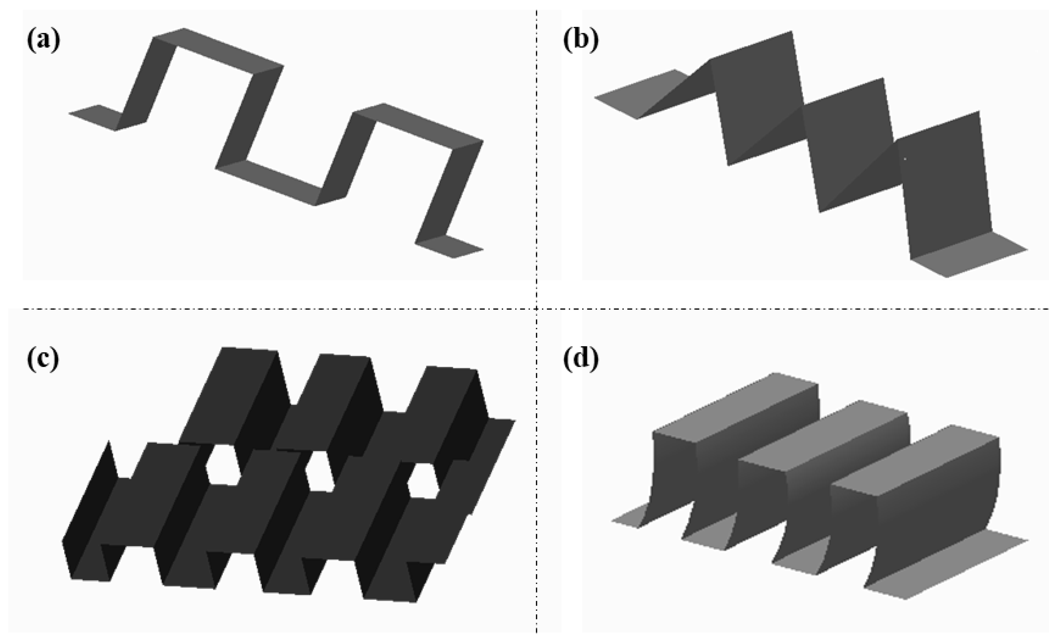
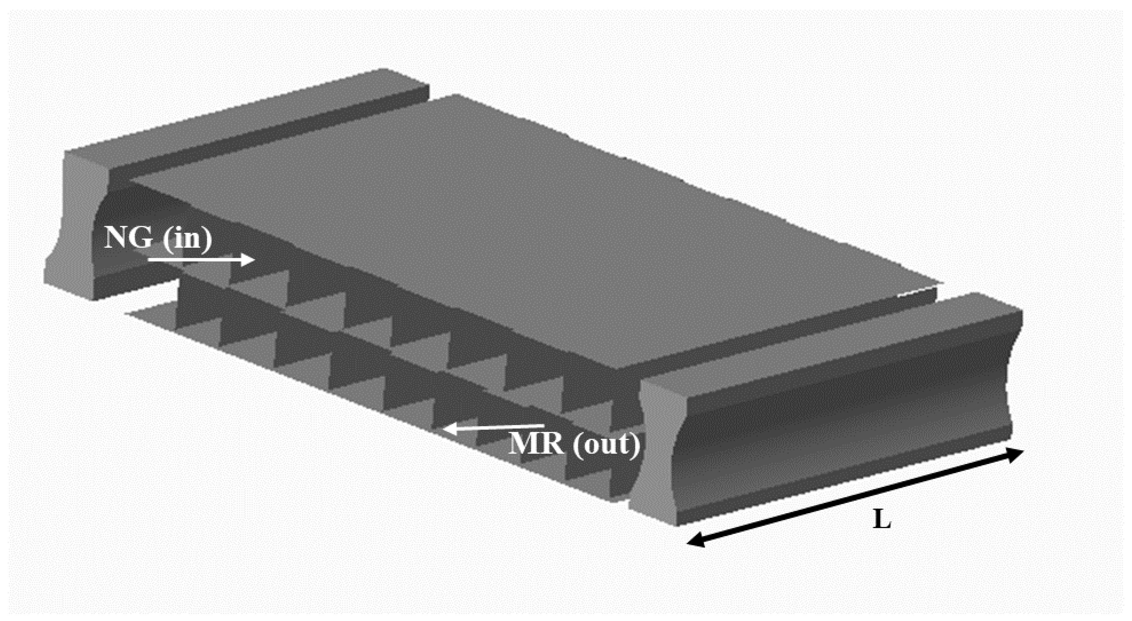
PFHE is a simple but critical part of any LNG plant. Due to the symmetry of PFHE, a very short length along the MR side is studied. In PFHE, plain fins are most common for LNG industry but new designs of fins are introduced to increase the efficiency of PFHE as shown in
Figure 1 [
21].
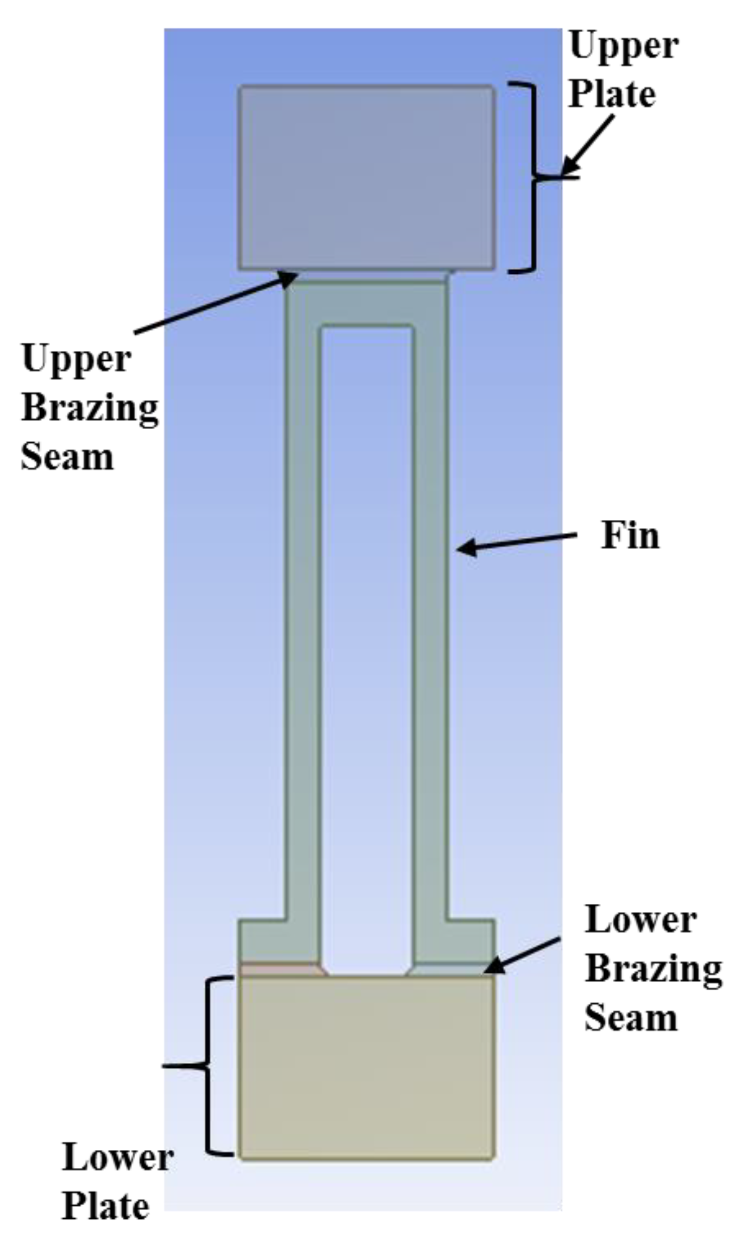
In this analysis, first, FEM is used to create the models of three fins. The PFHE comprises the upper plate, brazing seam, fin, lower brazing seam and lower plate as shown in
Figure 2.
ANSYS software is used for structural thermal coupling analysis. In ANSYS software, realistic/actual working conditions are simulated in terms of thermal and pressure loads. Von Mises theory is used for this type of analysis. Equivalent stress is calculated using Von Mises theory [
22] as,
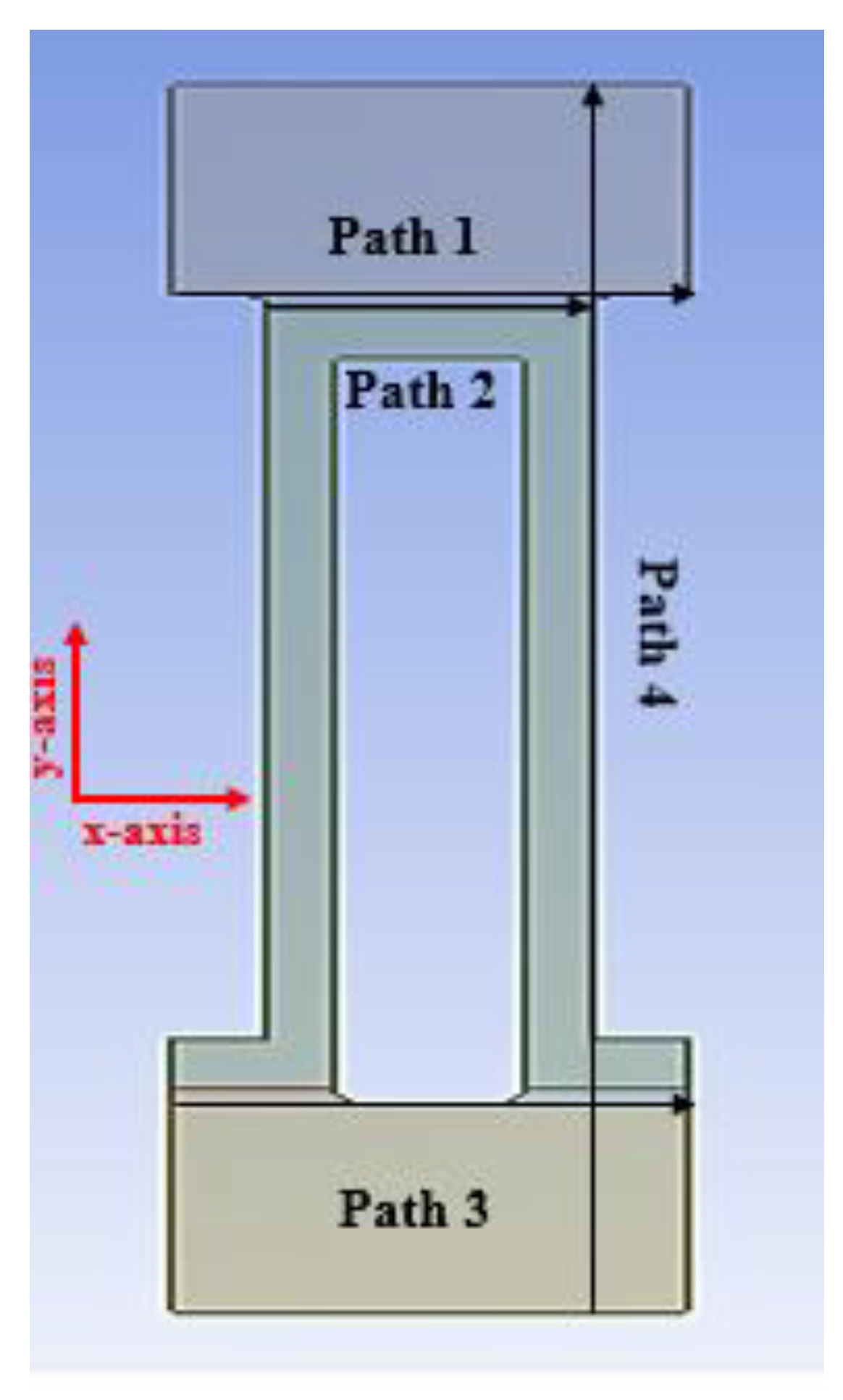
Stresses are analyzed along four defined paths of plain, wavy and compound brazing seam as shown in
Figure 3.
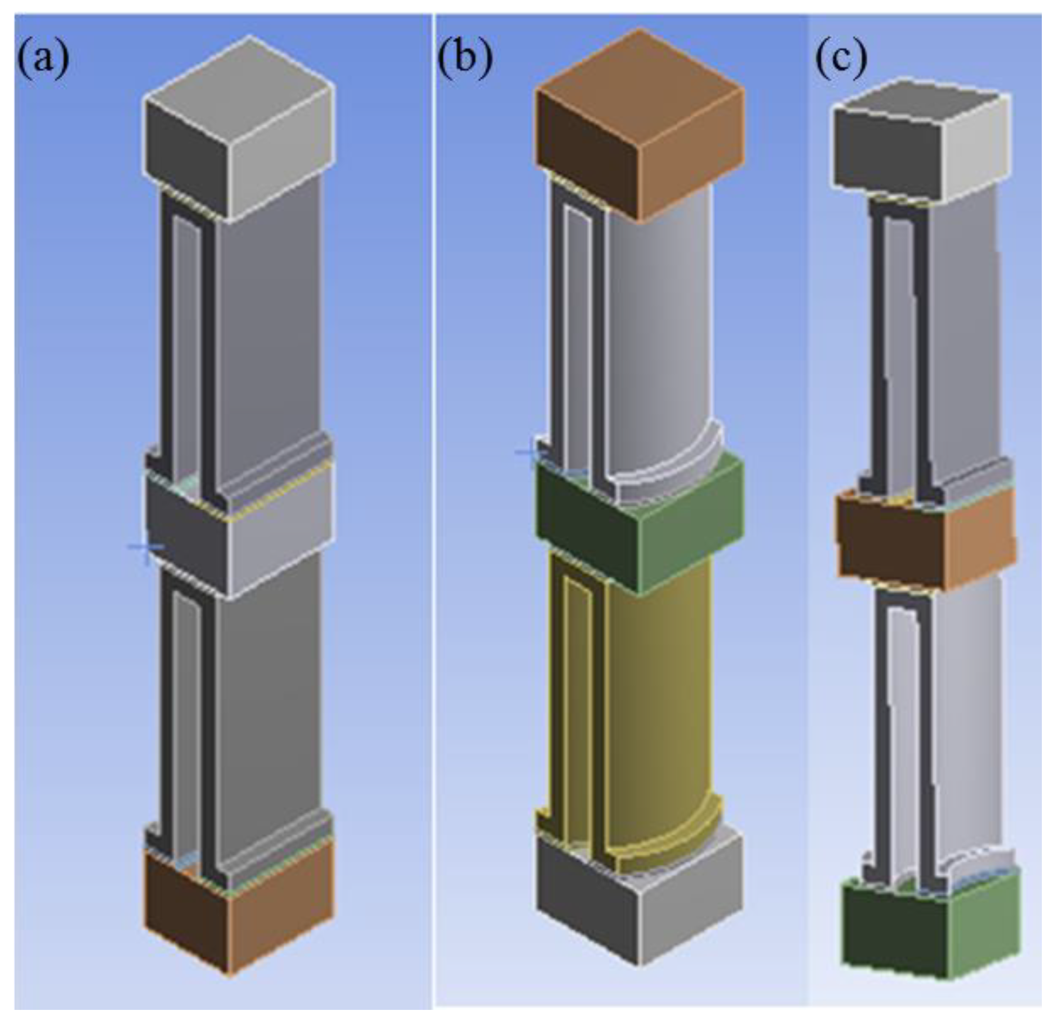
In this analysis, stresses are calculated at MR entrance for very short length due to the symmetry of the PFHE. Equivalent, normal and shear stress are calculated along each path. Three different fins combinations are used in this analysis: plain fin, wavy fin and compound fin configuration as shown in
Figure 4.
Same conditions are applied to all three different fin types using FEM. After calculating normal and shear stresses from FEM, FOS is calculated using experimental validation. Factor of safety is the ratio between strength of material to applied load on the material [
23] and defined as,
In order to assess the decrease/increase in strength due to brazing, experimentation is performed. For experimentation, a brazed joint is made using aluminum 3003 and aluminum 4004 following American Society for Testing and Materials (ASTM) standard E8-99 [
24]. In the previous studies individual material strengths were used for analysis, but in this analysis, first, a brazed joint is made and then the actual strength of the brazed joint is calculated for aluminum 3003 and aluminum 4004 joint which was much lower than single material strength. Due to this low strength of aluminum joint fins can be better analyzed for safety by using it to define FOS. This decrease in strength is due to invariabilities in the brazing process [
19,
25]. A Universal Testing Machine (UTM) is used for measuring tensile strength of the brazed joints [
26]. On the basis of this strength, FOS is defined along each path as well as for each configuration.
Four different paths are defined for this analysis as shown in
Figure 3. Three paths are for horizontal strength measurement of the PFHE brazed joint and one path is for vertical strength measurement of the PFHE brazed joint. In this analysis, counter flow is presumed. NG enters at temperature of 210 K, exchanges heat with MR, and leaves PFHE at a temperature of 150 K in cooled state whereas MR exchanges heat with NG in the PFHE at 155 K and leaves at 215 K. The pressure of NG is 7.1 MPa during this process. MR is at pressure of 0.4 MPa during this process. The heat transfer coefficient for NG is h
NG = 1.5 kW/(m
2 K), and for MR it is h
MR = 1.0 kW/(m
2 K). When NG or MR enters the fin, it exchanges heat by convection and conduction process and transfers to the intermediate plate through which this heat is exchanged with MR [
27]. The above conditions are applied to three different fins using commercial software to find critical areas in these different fin brazing seams and safest will be recommended for future use.
ANSYS software is used here for analyzing PFHE fins. Generally, tetrahedral and hexahedral elements are used in this type of analysis but in this study, hexahedral elements are used because they converge swiftly as compared to tetrahedral elements [
19,
28]. Hence, less memory is required for the solution when using hexahedral elements instead of tetrahedral elements. Element size of 1 mm, 0.5 mm and 0.01 mm are initially used that resulted in 303,008, 303,481 and 353,071 cells respectively. Mesh independency is obtained at element size of 0.01 mm that is employed for the current study. In this analysis, structural thermal coupling is used. Furthermore, pressures are applied followed by temperature heat transfer in thermal analysis with actual PFHE dimensions and boundary conditions. The impact of external load is ignored because in actual working conditions PFHE can expand and shrink independently due to sliding frames below the PFHE structure [
29].
Figure 5 presents the meshed geometry of braze and plate fin.
Transition ratio of 0.272 and growth rate of 1.2 were employed with some assumptions. Following assumptions are employed for brazed seam.
- 1.
Effect of layer number is not considered due to symmetry of PFHE.
- 2.
Alternating counter flow is assumed for (NS) and (MR) or first analysis.
- 3.
Material properties such as linear elasticity and isotropy depend on temperature.
- 4.
Elastic deformation occurs both in metal and braze as it is a comparative analysis of three different fins, not individual strength analysis.
Due to symmetry, only one unit of the PFHE is analyzed. Length (
L) is used because there is small change in temperature for this length shown in
Figure 6. For keeping NG in liquid form, it exchanges heat with (MR) in counter flow direction and the flow assembly could be seen in
Figure 6 [
20]. Dimensions of fins used in this analysis are shown in
Table 1.
Two materials are used in PFHE, where Al3003 is the base material and Al4004 is used as filler material. In earlier studies, pre-brazed strength was used but post-brazed strength is used here since the experimental evidence show that the strength is reduced so actual strength is used for better structural stability. The properties of both materials under different temperature conditions are shown in
Table 2.
Experimental Validation
In this section, strength of Al 3003 and Al 4004 brazed joint is calculated. Al 3003 is manganese base alloy and Al 4004 is silicone alloy. In this analysis, Al 3003 and Al 4004 are a brazed joint. Al 3003 is used as base material and Al4004 is used as filler material.
In earlier analysis, actual strength of both materials was used but in current study, actual brazed strength is used which is lower than actual individual material strength. After calculating standard experimental brazed strength it is compared to the ASTM strength of aluminum brazed joints, which followed the same trends, and is reduced as compared to base material strength which was earlier used by researchers [
31,
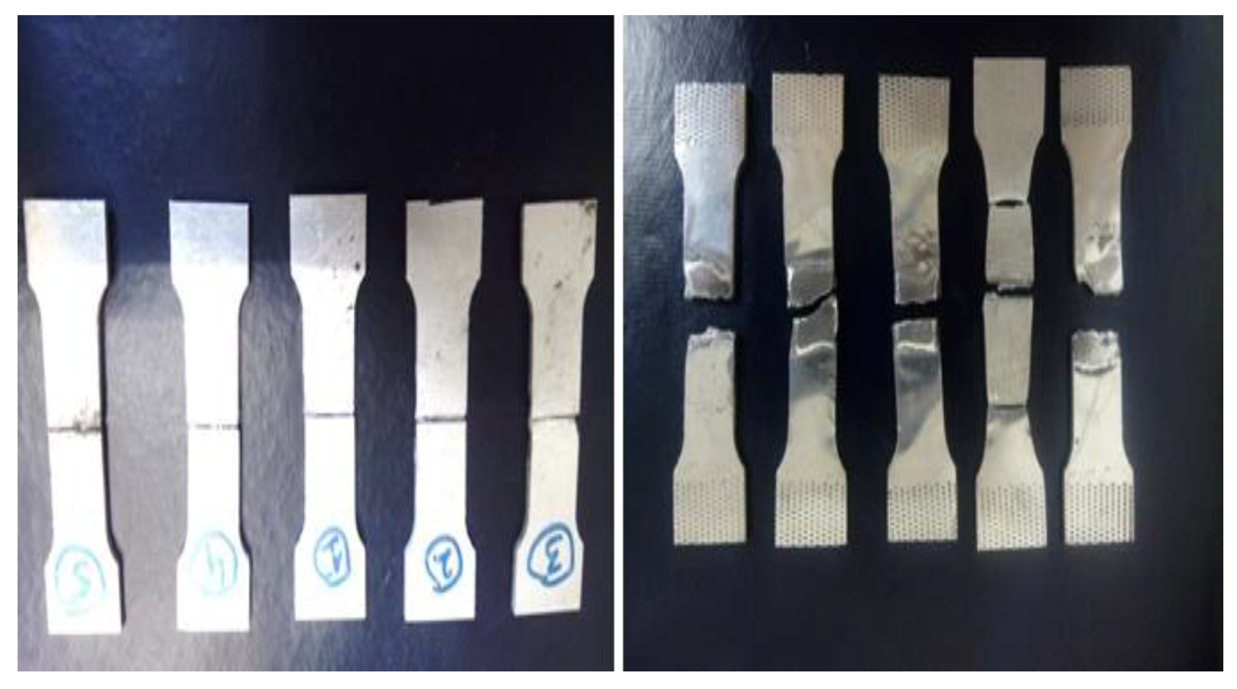
34]. To validate our results for FOS in the Al 3003 and Al 4004 brazing joint, a tensile test is performed for these materials joints. Standard Al3003 sample of thickness 2 mm is made and brazed with Al4004 filler material. ASTM standard E8-99 is used for samples shown in
Figure 7 [
24].
Al 4004 pre-brazed strength is 142 MPa which was used in earlier analysis as failure strength [
31], but from the experiment its post-brazed strength is estimated to be 112 MPa due to invariabilities in brazing processes [
25]. Hence this new brazing strength is used in analysis to redefine FOS and MOS for PFHE.
For the uniaxial test equivalent, stress is,
Equivalent stress has direct relationship with yield strength in case of uniaxial testing. But in actual conditions, due to different invariabilities, actual strength of joint is decreased to 112 MPa at normal temperature. Hence, by using this lower yield strength of material brazing joint, the PFHE design can be made, safer and reliable during actual working conditions.
3. Results
In this section, maximum stress magnitudes with FOS will be discussed for three different fin types i.e., plain, wavy and compound fin. These magnitudes are helpful in understanding the structure stability of three different fins along four different paths. Stresses along each path will be concluded with the reason for the increase in stress for a particular fin-brazed seam. Equivalent, normal and shear stress along four paths with three different fin types are presented in following section. With these stresses and post-brazed strength calculated from experimental validation will be helpful in defining FOS for all three fin configurations.
3.1. Stresses along Path 1
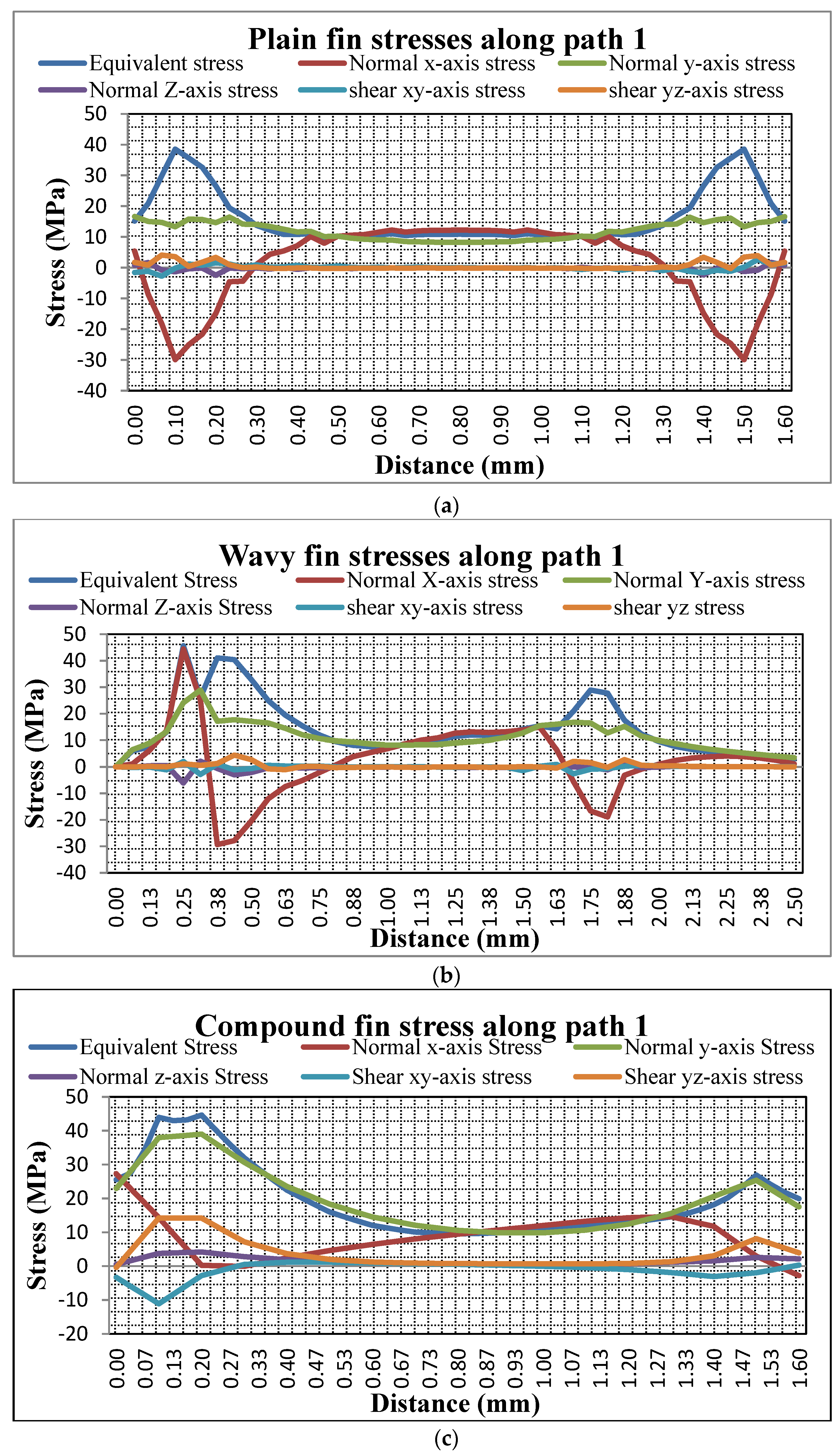
In this section, equivalent, normal and shear stresses are calculated for plain, wavy and compound fin-brazed seams along path 1 as shown in
Figure 8. These stresses are used to define FOS for each stress type. As shown in
Figure 8a, equivalent, normal and shear stress are calculated along path 1 of the plain brazed seam. It is important to note that equivalent stress is maximum on both left and right side of the brazed seam with a magnitude of 38 MPa and stress magnitude is minimum at the center of the brazed seam with stress of 12 MPa. Similarly, as shown in
Figure 8a, normal x-stress is maximum at both left and right sides of the brazed seam with magnitude of −30 MPa, and minimum stress of 15 MPa is at center of brazed seam. Compressive yield strength of aluminum alloys is approximately same as tensile yield strength [
35]. Normal stress along y-axis reaches maximum value of 18 MPa as shown in
Figure 8a. Moreover, it can be comprehended that z-axis stress has magnitude of 2.43 MPa on the left and right sides of the fin-brazed seam. Shear stress x-y has maximum magnitude of 2.76 MPa, and lastly, y-z stress reaches a maximum magnitude of 4.10 MPa.
Similarly, equivalent, normal and shear stress are calculated for the wavy fin-brazed seam along path 1 as shown in
Figure 8b. In this case, a different stress phenomenon is observed as compared to the plain fin-brazed seam due to curved nature of fins as shown in
Figure 4 earlier. Due to curve nature of wavy fins, the load is not eccentric with axis of fin as in case of plain fin, which causes increase in stress at the inner curvature (left side of fin) and decrease in stress at outer curvature (right side of fin). Equivalent stress in a wavy fin reaches a maximum magnitude of 47 MPa on left side of fin and 27 MPa on right side of fin as compared to plain fin as shown in
Figure 8b. Normal x-axis stress in the case of the wavy fin on the left side of the fin-brazed seam reaches a magnitude of 45 MPa and 20 MPa on right side of fin brazed seam which is higher than plain fin.
Similarly, y-axis stress is 30 MPa on the left side of the brazed fin seam and 18 MPa on right side of fin. It is also higher in wavy fin as compared to plain fin due to inward curvature on left side of fin. Z-axis stress reached a maximum stress of 6.13 MPa which is higher than plain fin. X-y and y-z shear stress in this brazed seam is 2.86 MPa and 4.45 MPa, respectively, which is also higher than plain fin. Shear yield strength is generally 55% of normal yield strength in aluminum alloys [
35].
The compound fin-brazed seam along path1 is analyzed as seen in
Figure 8c. Equivalent stress on the left side of the compound fin brazed seam is 45 MPa and 25 MPa on the right side of the brazed seam fin. In the middle of the brazed seam, stress magnitude is 10 MPa. This stress is higher than the plain fin-brazed seam but lower than the wavy fin. This interesting phenomenon is due to two different fins used in the compound fin configuration as compared to plain and wavy fin brazed seam as previously presented in in
Figure 4.
Normal x-axis stress on the left side of the compound fin-brazed seam is 28 MPa and 15 MPa on the right side which is the lowest of the three fin-brazed seam configurations. On the left side of the compound fin-brazed seam, y-axis stress magnitude is 38 MPa and 25 MPa on the right side of the brazed fin seam. Z-axis stress in the case of the compound fin-brazed seam reached a maximum value of 4.17 MPa which is lower than the wavy fin and higher than the plain fin. Finally, x-y and y-z axis shear stress are 11 MPa and 14 MPa respectively which is higher than both the plain and wavy fins, as shown in
Figure 8c.
From the above discussion it can be concluded that along path 1 in case of the compound fin, equivalent stress is increased by 16% as compared to the plain fin and 5% decrease is observed in the wavy fin. Normal x-axis stress in the compound fin is 7% lower than the plain fin and 34% lesser than the wavy fin. Y-axis stress for the compound fin is 47% higher as compared to the plain fin and 22% higher than the wavy fin. Along path 1 normal z-axis stress and shear stresses have no significance for structural stability of fin-brazed seams. Therefore, due to equivalent stress and y-axis stresses along path 1 the compound fin is most likely to fail first. The above brazed seam in plain, wavy and compound fin configurations is between Al 3003 and Al 4004, in which the brazed material is Al 4004 and it is weaker among two aluminum alloys, hence its post brazing strength was used to define FOS [
36]. Minimum FOS is for the compound fin in the case of equivalent stress and y-axis stress, whereas it is increased in the case of x-axis stress as compared to plain and wavy fin brazed-seam configurations. FOS is presented for plain, wavy and compound configurations along Path 1 below in
Table 3.
The above table shows that FOS is less in the case of the compound fin as compared to the plain and wavy fins and most likely to fail first. Hence, if there is a failure in the compound fin configuration, the crack will initiate in the y-axis direction of the brazed seam, having least FOS in this direction. Similarly, if the wavy fin fails, most likely crack will start in x-axis direction of brazed fin seam. Finally, the plain fin which is safest of all, the cracks in the brazed joint mostly likely will be produced in x-axis direction.
3.2. Stresses along Path 2
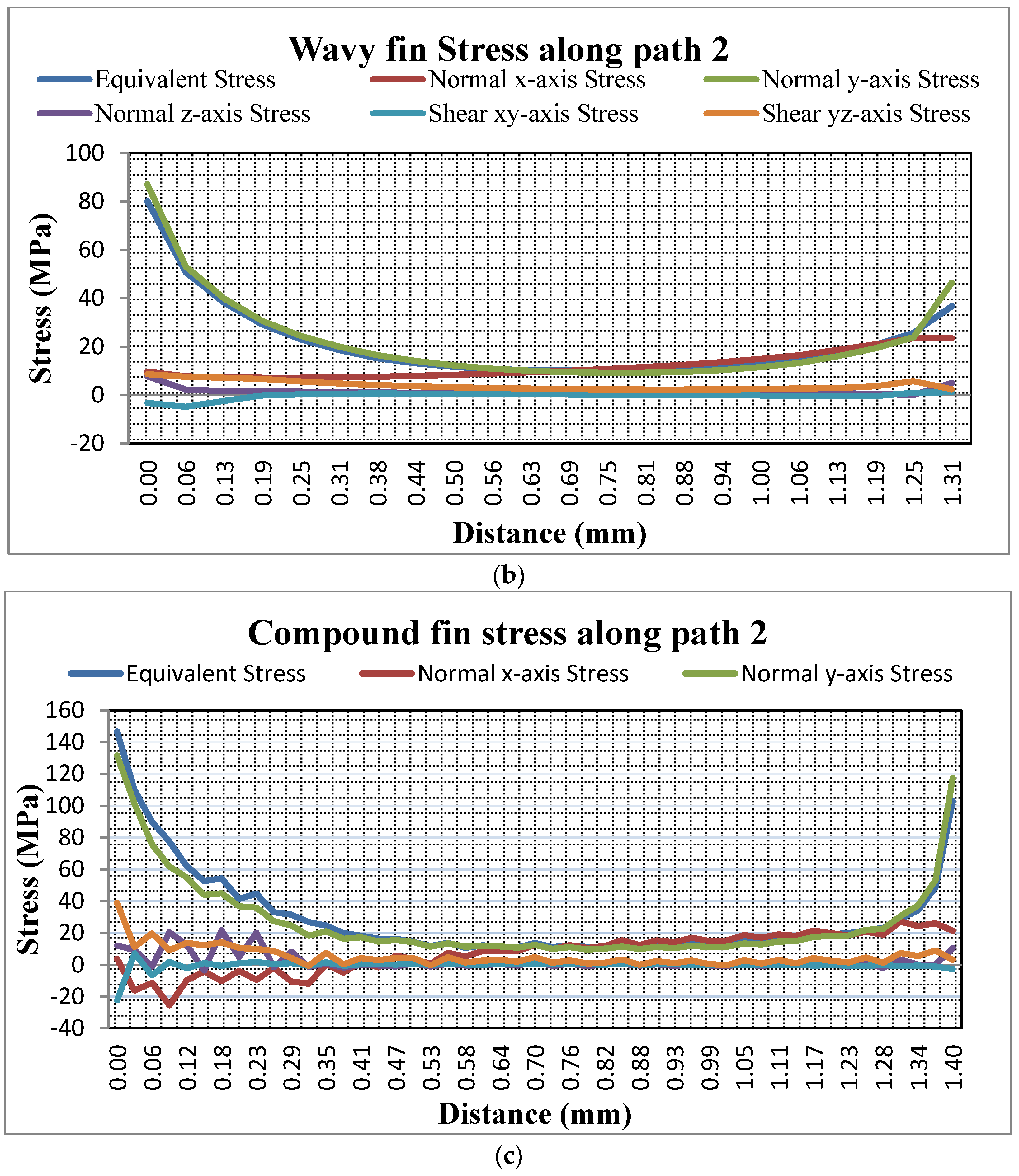
In this section, stresses along path 2 for plain, wavy and compound fin brazed seam configurations are analyzed as shown in
Figure 9. In
Figure 9a stresses in the plain fin brazed seam configuration along path 2 is shown. Equivalent stress along path 2 for plain fin is 74 MPa on the left and right side of the fin brazed seam while it is 15 MPa at the center of fin brazed seam. Normal x-axis stress is 10 MPa on both ends of fin brazed seam whereas it is 15 MPa at the center of the brazed seam. It is important to mention that the y-axis stress has significant effect on the structural stability of the plain fin: it reaches a maximum magnitude of 85 MPa on left and right side of fin brazed seam and 10 MPA at center of the brazed seam. Furthermore, it can be seen that z-axis stress reaches a maximum magnitude of 18 MPa on both ends of the fin brazed seam; it is zero at the center of the fin seam. Shear x-y and y-z stress have no significance on structure stability of fin. X-y shear stress reaches a maximum magnitude of 2 MPa whereas a maximum of 6 MPa is observed in y-z shear stress.
Figure 9b examines the wavy fin brazed seam configuration along path 2 for equivalent, normal and shear stress. As previously observed in the wavy fin brazed seam configuration, stress is not same on both ends of the brazed seam. It is maximum on left side of braze seam and decreases to half on the right side of the brazed seam. The primary reason is that load is not eccentric with the axis of the wavy fin. Equivalent stress is 80 MPa on the left side of the fin, 36 MPa on the right side of the fin and 10 MPA in the middle. Normal x-axis stress is 10 MPa on the left side of the fin and 23 MPa on the right side of the fin. Due to unsymmetrical load along y-axis, stress on the left side of the fin is 84 MPa and 46 MPa on the right side. Normal z-axis as shown in
Figure 9b is 7 MPa on the left side of the brazed seam and 5 MPa on the right side. Shear stress xy reaches a maximum magnitude of 5 MPa whereas yz shear stress is 8 MPa.
In
Figure 9c along path 2, equivalent, normal and shear stresses for the compound fin brazed seam are presented. This path is very critical for compound fin brazed seam configuration failure. Equivalent stress on the left side of the brazed seam for compound configuration is 147 MPa, which is way beyond the yield strength of the brazed joint strength of 112 MPa due to which most probably failure will occur in the compound fin and on the right side of the fin brazed seam 102 MPa was observed which is also close to the brazed joint yield strength. It can be seen in
Figure 9c that along x-axis, maximum magnitude of 25 MPa is observed on the left side of the fin brazed seam and 26 MPa on the right side of the fin brazed seam. Y axis normal stress is also critical for the compound fin failure. It is observed to be of magnitude 132 MPa on the left side and 117 MPa on the other end. Maximum magnitude of 21 MPa is observed in the compound fin configuration for z-axis stress along path 2. Shear xy stress reached a maximum magnitude of 22 MPa and yz shear stress reached a magnitude of 39 MPa which is critical for failure.
Along path 2 it can be concluded that as compared to the plain fin brazed seam, in the case of the compound fin and wavy fin brazed seams, equivalent stress is increased by 50% and 8 % respectively. Normal x-axis stress increased by 30% and 35% in the case of the compound and wavy fins, in contrast to the plain fin. Normal y-axis stress increased by 35 % in the compound fin and no significant change in the case of wavy as compared to the plain fin is observed, z-axis normal stress increased by 15% and 60% in the compound and wavy fins as compared to the plain fin. Shear stress is significantly increased in the case of the compound fin brazed configuration. Importantly along path 2 compound fins are most likely to fail. Factor of safety is presented in
Table 4 for the above three cases of fin brazed seams.
The above table shows that along path 2, FOS in the case of equivalent stress and y-axis is most critical for the compound fin configuration. Similarly, it is reduced along the x-axis, z-axis and x-y shear stress for the compound fin which indicates early failure as compared to other fin configurations. Now if a crack initiates in the compound fin configuration it will initiate in the y-axis direction of the fin brazed seam. For the wavy fin brazed seam, crack propagation will initiate due to y-axis stress along the y-axis direction, having a minimum value of FOS along this direction. In the case of the plain fin the magnitude of FOS along each direction as compared to other fin configurations shows that it will be the safest brazed seam. Most likely, the crack will initiate due to y-axis stress along y direction followed by shear yz-axis stress.
3.3. Equivalent Stresses along Path 3
In this section, stresses along path 3 for plain, wavy and compound fin brazed seam are investigated as shown in
Figure 10. For the plain fin brazed seam, it could be seen that equivalent stress reached a maximum magnitude of 40 MPa on both ends of the seam, and in the middle of the brazed seam maximum amplitude of 20 MPa is observed for equivalent stress. Normal x-axis stress reached a maximum magnitude of 18 MPa in the middle of the brazed seam whereas it is 8 MPa on both ends of brazed seam. In addition, y-axis normal stress reached a maximum amplitude of 33 MPa on both ends of the brazed seam and stress is dropped to 20 MPa in the mid of brazed seam. It is important to note that maximum z-axis stress of 4 MPa is observed for the plain fin brazed seam along path 3. X-y and y-z shear stress along this path of the brazed seam is of magnitude 4 MPa and 13 MPa respectively as shown in
Figure 10a.
For the wavy fin brazed seam, similar observations are made as previously noted. Equivalent stress magnitudes is different on both ends of the fin brazed seam with maximum magnitude of 21 MPa observed on the left side of the fin brazed seam whereas 43 MPa of stress magnitude is observed on right side of the fin brazed seam. Normal x-axis stress is of amplitude 10 MPa on the left side of fin whereas it is 36 MPa on the right side of the fin brazed seam. Y-axis normal stress is 20 MPa on the left side of the fin brazed seam and 41 MPa on the right side of the fin brazed seam. Moreover, maximum magnitude of 3 MPa is observed for z-axis stress along path 3 for the wavy fin brazed seam. X-y and y-z shear stress maximum magnitude are 9 MPa and 13 MPa, respectively.
Similarly, the compound fin brazed seam along path 3 is presented as shown in
Figure 10c. Equivalent stress is of amplitude 20 MPa on the left side of the brazed seam and 44 MPa on the right side of the fin seam, in the mid it is 15 MPa. Normal x-axis stress is of amplitude 8 MPa on the left side of the fin brazed seam and 36 MPa on the right side of the fin. Y-axis normal stress is 20 MPa on the left side of the brazed seam and 41 MPa on the right side of seam. A maximum of 5 MPa of stress magnitude is observed along z-axis normal stress. X-y and y-z shear stress both reached maximum amplitude of 13 MPa along the fin brazed seam.
Stresses along path 3 concludes that equivalent stress in the case of compound fin increased by 10% as compared to the plain fin brazed seam and 3% more than the wavy fin. Normal x-axis stress doubled as compared to plain stress in the case of the compound and wavy fin brazed seams. Y-axis stress increased by 20% in the case of the compound and wavy fins as compared to plain fin brazed seam. There is no significant effect along z-axis for all three fin brazed seam types. Shear stress remains the same for all three cases of brazed seam. Path 3 is also not safe for the compound fin brazed seam due to the increase in stress as compared to the plain and wavy fin brazed seam configurations.
Table 5 presents the FOS for all three cases discussed above.
FOS indicates along path 3 that the compound fin is most likely to suffer to early failure as compared to other configurations. In the compound fin brazed seam configuration, the crack in the brazed seam will initiate along the y-axis direction due to the lowest value of FOS along this direction. Furthermore, the wavy fin is also most venerable along the y-axis direction and the crack will initiate along this direction of seam. Lastly, the plain fin brazed seam which is the safest of all, will also fail along the y-axis direction according to above calculations.
3.4. Stresses along path 4
Stresses along path 4 are discussed in
Figure 11 for plain, wavy and compound fin brazed seam configurations. Equivalent stress having a maximum magnitude of 94 MPa along path 4 of the plain fin brazed seam is shown in
Figure 11a. Normal x-axis stress reached a maximum amplitude of 55 MPa. Y-axis stress reached a magnitude of 54 MPa. Maximum of 3 MPa of stress is observed in the case of z-axis stress. A magnitude of 46 MPa is observed along x-y shear axis, which is critical for failure. Y-z shear stress reached amplitude of 15 MPa along path 4 of the fin brazed seam.
In
Figure 11b, the wavy fin brazed seam is analyzed along path 4 of the fin brazed seam. It could be seen that equivalent stress reached a maximum magnitude of 91 MPa along path 4 for the fin brazed seam. Normal x-axis stress maximum magnitude is 18 MPa. Y-axis normal stress is 20 MPa along path 4 of the wavy fin brazed seam. Along the z-axis, 1 MPa is observed for wavy fin brazed seam. X-y shear stress along path 4 of the wavy fin brazed seam is 50 MPa and y-z axis stress is 17 MPa. The compound fin brazed seam along path 4 is analyzed and the results are presented in
Figure 11c. The maximum equivalent stress magnitude is 82 MPa and normal x-axis stress reached a maximum magnitude of 15 MPa. Y-axis maximum stress along path 4 of the compound fin brazed seam is of magnitude 23 MPa. A maximum of 2 MPa of stress is observed along z-axis. X-y axis shear stress reached a maximum magnitude of 46 MPa, and 19 MPa is observed for y-z axis shear stress.
Along path 4, it could be concluded that in the compound fin brazed seam equivalent stress is decreased by 13% as compared to the plain fin and the wavy fin is 4% safer than plain fin brazed seam in case of equivalent stress. Normal x and y axis are very dominant in the plain fin as compared to the wavy and compound fins. Z-axis stress remained safe for all plain, wavy and compound fin configurations. X-y stress is critical for failure in the cases of compound and wavy fin configurations, but it is quite safe in the case of the plain fin. Finally, y-z stress is safe for all, plain, wavy and compound fin brazed seam configuration. Along this path, plain fin is safer than the compound fin in case of equivalent stress, but normal x-axis stress along this path is also dominant for the plain fin as compared to compound and wavy fin. Factor of safety is shown in
Table 6 for the above three cases along path 4.
For path 4, FOS is better for the compound fin in the case of normal x-axis stress, but for y-axis and shear stresses the plain fin is a much safer option. Along this path, the compound fin brazed seam will most likely fail due to shear stress. Minimum FOS for the compound fin brazed seam configuration is observed along xy-axis shear stress. For the wavy fin brazed seam configuration, shear xy-axis stress is most critical and failure will initiate due to this stress. Finally, the plain fin brazed seam will also fail first due to xy-axis shear stress.
3.5. Failure Criteria on the Basis of Interaction Equation
FOS is already discussed in above section, to analyze structural stability of the brazing joints in PFHE, in term of normal and shear stresses to reassess the finding. Another technique of the interaction equation is used here which is commonly used for brazing joint strength analysis, and in this analysis interaction equations are used along four paths of fin brazed seam for plain, wavy and compound configurations. A general interaction equation is employed which was designed to test brazed joint strength. Their main significance is that the cumulative damage by both shear and normal stress can be analyzed simultaneously as compared to other strength equations in which the effect of one stress at a time normal or shear is examined [
37]. The interaction equation is defined as,
where
These equations can best predict the failure due to combine loading as in this case. In earlier studies only one stress was analyzed at a time but by using these equations we can calculate the combine effect of two different stresses on the fin brazed seam simultaneously. In
Table 7, stresses along four paths for plain, wavy and compound fin configuration are analyzed using interaction equation.
According to the above interaction equations in
Table 7, it can be seen that path 4 is critical for all three fins and y axis stress along path 2 is the main cause of concern for a compound fin as mentioned by yield theory.
4. Conclusions
In this study, the structural stability of PFHE fins considering three configurations, plain, wavy and compound, is investigated along 4 paths. It can be concluded that:
- (a)
Along the path 1, y-axis normal stress is most critical from the PFHE fin failure point of view. Y-axis stress for compound fin is 47% higher as compared to plain fin and 22% higher than wavy fin. Due to y-axis stress along path 1, the compound fin is most likely to fail first.
- (b)
Stresses along path 2 are critical for all three fin types. In case of equivalent stress there is 50% and 8% increase in the compound and wavy fins as compared to the plain fin. X-axis normal stress increased by 30% and 35% in case of compound and wavy fin in contrast to plain fin brazed seam. There is 35% increase in stress in the case of the compound fin as compared to the plain fin along y-axis stress; wavy fin stress followed the pattern of plain fin. Large increases in stress of 15% and 60% are observed for the compound and wavy fins as compared to the plain fin along z-axis. Shear stress is significantly increased in the case of the compound fin brazed configuration. Even along path 2, compound fins are most likely to fail.
- (c)
Normal x-axis stress is most critical along path 3 for compound fin configuration. Along this path the stress is doubled in the case of the compound and wavy fins as compared to the plain fin brazed seam. Path 3 is also not safe for the compound fin brazed seam as compared to the plain and wavy fin brazed seam configurations.
- (d)
Along path 4, normal x and y axis stresses are more dominant in the case of the plain fin brazed seam as compared to the wavy and compound fin brazed seam configurations. X-y shear stress is higher in magnitude in the case of the compound and wavy fin brazed seams as compared to the plain fin. In the case of equivalent stress, the plain fin is quite safe along this path but normal stresses are dominant for the plain fin as compared to the compound and wavy fin brazed seam configurations.
From the above discussion, it can be concluded that the compound fin brazed seam is most vulnerable to all equivalent, normal and shear stresses. The compound fin configuration under the same conditions is most likely to fail first. The wavy fin configuration is weaker than the plain fin configuration in case of equivalent and shear stress, but in the case of normal stress, it is more resistant to failure as compared to the plain fin brazed seam configuration. Furthermore, it can be concluded that the plain fin configuration is better than the compound fin configuration in the case of all three stresses i.e., normal, shear and equivalent stress, but in the case of normal stresses, the wavy fin configuration is better than the plain fin configuration. By this we can conclude that if a single fin has a plain shape at the start and followed by a wavy shape, the plain portion of the fin is more reliable against shear and equivalent stress whereas the wavy portion will be more reliable against normal stress. Therefore, a better brazed joint having more reliability against normal stress can be used for the plain fin whereas the wavy fin is more reliable with a better shear resistance joint.
One interesting phenomenon was observed during this simulation. The plain fin brazed seams configuration stress magnitude is same on both sides of the fin, but in the case of the wavy and compound fin brazed seams, variable stress magnitude was observed on both sides of the fin, which indicates fatigue. Therefore, it can be concluded that future work on fatigue analysis of wavy and compound fin configurations can give a better picture of failures in these brazed seams.
