Article

A Preliminary Techno-Economic Analysis on the Calcium Looping Process with Simultaneous Capture of CO2 and SO2 from a Coal-Based Combustion Power Plant

1
Istituto di Ricerche sulla Combustione, Consiglio Nazionale delle Ricerche, Piazzale Vincenzo Tecchio 80, 80125 Napoli, Italy
2
Dipartimento di Ingegneria Chimica, dei Materiali e della Produzione Industriale, Università degli Studi di Napoli Federico II, Piazzale Vincenzo Tecchio 80, 80125 Napoli, Italy
*
Author to whom correspondence should be addressed.
Energies 2020, 13(9), 2176; https://doi.org/10.3390/en13092176
Submission received: 20 March 2020 / Revised: 18 April 2020 / Accepted: 22 April 2020 / Published: 1 May 2020
(This article belongs to the Special Issue Coal Conversion Processes)

Abstract

:
The increase of capital investments and operation and maintenance (O&M) costs represents a current limitation to the diffusion of carbon capture systems for the clean combustion of fossil fuels. However, post-combustion systems, such as calcium looping (CaL), for CO2 capture from flue gas are the most attractive carbon capture systems since they can be installed at new plants and retrofitted into existing power plants. This work investigates the pros and cons of employing a calcium looping system for CO2 capture and also as a desulphurization unit. A preliminary techno-economic analysis was carried out comparing a base case consisting of a coal-based power plant of about 550MWe with a desulphurization unit (Case 1), the same plant but with a CaL system added for CO2 capture (Case 2), or the same plant but with a CaL system for simultaneous capture of CO2 and SO2 and the removal of the desulphurization unit (Case 3). Case 2 resulted in a 67% increase of capital investment with respect to the benchmark case, while the increase was lower (48%) in Case 3. In terms of O&M costs, the most important item was represented by the yearly maintenance cost of the desulphurization unit. In fact, in Case 3, a reduction of O&M costs of about 8% was observed with respect to Case 2.

1. Introduction

Currently, energy from coal accounts for about 30% of the total global energy supply, as reported in the IEA World Energy Outlook [1]. Moreover, despite the Paris agreement in 2015 (COP-21), a growth of coal demand of about 0.4% per year is expected up until 2040. However, this value represents an optimistic view, because it is based on declared policy intentions, which may not be respected by the signatory countries. Therefore, the role of fossil fuels will most likely still be relevant for many years, with the consequence that significant emissions to the atmosphere of anthropogenic greenhouse gases, especially CO2, will continue.
The utilization of specific measures are necessary to face climate change. In this regard, in the EU, the Emission Trading System (ETS) regulates the greenhouse gas emissions of the energy sector; they had aimed for a decrease with respect to 2005 levels of 21% by 2020, which, as proposed by the European Commission, could reach 43% by 2030. This represents an important tool to drive energy companies to invest in technologies to limit CO2 emissions.
Carbon capture and storage (CCS) and more recently carbon capture and utilization (CCU) technologies represent attractive choices for the sustainable employment of fossil fuels. Generally, the main drawback for the diffusion of these technologies, besides those of a technical nature, is related to the significant capital investments and the operation and maintenance (O&M) costs.
Within these technologies, post-combustion CO2 capture has a major advantage in that it can be installed on existing power plants (retrofit). In particular, the calcium looping technology (CaL) is very attractive since cheap, natural, Ca-based sorbents, such as limestone and dolomite, are employed [2,3,4,5,6,7,8,9,10]. This process is based on a reversible carbonation reaction (CaO + CO2 = CaCO3) and typically consists of two interconnected fluidized beds: the carbonator and the calciner. In the carbonator, CaO particles react with the CO2 in the flue gas coming from the power plant to form CaCO3 that is then transferred into the calciner where the calcination reaction takes place and restores the CaO reactant. The reactant can then be transferred back into the carbonator, restarting a new cycle. At the outlet of the calciner, a stream composed mainly by CO2 can be either sent for compression and storage (CCS) or used for other purposes (CCU).
The endothermicity of the calcination reaction can be sustained by the combustion of an auxiliary (and cheap) fuel under oxy-combustion mode with pure oxygen provided by an ancillary air separation unit (ASU). Another recently proposed possibility, which is still in an early research stage, is based on the combination of the calciner with a concentrated solar power system [11,12].
In the last decade, many efforts by several research groups around the world have been carried out in order to study, improve, and make feasible the CaL process. The main issue with this technology is the strong deactivation of the sorbent material with the number of cycles experienced by the particles: This decay is mainly due to the sintering phenomenon caused by the high temperatures in the process (especially in the calciner).
Another possible source of sorbent deactivation arises from the irreversible reaction of the sorbent with SO2, which produces CaSO4. SO2 is typically contained in the flue gas from coal combustion in the carbonator, but it may also be present in the calciner if coal is used as auxiliary fuel to sustain calcination. SO2 emissions are regulated in all countries, and the coal power plants are equipped with flue gas desulphurization devices in order to decrease the SO2 concentration to below the permitted limits. In general, this abatement is carried out in situ in the combustion chamber in the case of fluidized bed (FB) boilers, while wet scrubbers are typically used in the case of pulverized fuel (PF) boilers. In both cases, limestone or other alkaline materials are employed as SO2 sorbents. PF boilers are the most widespread units for coal combustion in connection with wet scrubbers for SO2 removal, which in general are affected by corrosion and water pollution problems and have high power requirements.
In this work, the possibility to eliminate the wet scrubber (and related issues) and to install a CaL system for the simultaneous capture of CO2 and SO2 in a PF boiler plant was investigated. In particular, a preliminary techno-economic analysis was carried out in order to understand the pros and cons of a such configuration in terms of capital investments and O&M costs. Three different plant configurations were considered in this work: (i) a PF power plant without a CaL system and with SO2 abatement by wet scrubbing, which is the benchmark configuration (Case 1); (ii) a PF power plant with a CaL system and with SO2 abatement by wet scrubbing (Case 2); and (iii) a PF power plant without the wet scrubber and with CaL used for simultaneous CO2 and SO2 capture (Case 3).
This study had two objectives: The first was to evaluate the advantages and disadvantages of carrying out desulfurization upstream or simultaneously with the capture of CO2; the second was to evaluate on the basis of current and future/possible European laws on greenhouse gas emissions the possibility of adding a CaL unit to an already existing plant using alternative strategies.

2. Description of Plant Configurations

As introduced before, three proposed configurations were investigated in this work:
  • Case 1 (Base Case): PF power plant without CaL system;
  • Case 2: PF power plant with CaL system; and
  • Case 3: PF power plant with CaL system for simultaneous capture of CO2 and SO2.
Table 1 reports the main design features of the scrutinized power plant and of the post-combustion CaL system.
The PF power plant has a sub-critical steam cycle at 170 bar/540 °C with one steam reheat at 39 bar/540 °C, and the performance indicators used for the evaluation are presented in Table 2 [4].
The hypotheses assumed in this analysis are that the nominal electrical power of the plant will not be less than 400 MWe and the expected CO2 capture will be greater than 90%.
The absence of a CO2 capture system in Case 1 means that about 800–900 Kg of CO2 are emitted per electric MWh. Indeed, this value falls to about 65–85 kg CO2/MWh in Cases 2 and 3. For Case 3, the CaL unit was designed on the basis of experimental data on CO2 capture, under low and high SO2 concentrations, from the same research group [13].
Obviously, the installation of a CO2 capture system (Cases 2–3) implies an energy penalty, with respect to the Base Case, quantifiable by about 5–10 net electricity percentage points. However, the CaL technology is preferable with respect to other consolidated solutions based on chemical gas-liquid absorption, which shows higher levels of energy penalty. Additionally, these systems also typically present a lower CO2 capture rate (<90%) than CaL [4,14,15,16].
The addition of a CaL system (Case 2) provides an increase of capital investment as well as the O&M costs. The possibility of relying on the CaL process for SO2 abatement, so eliminating the wet scrubber, could be a valid answer to reduce the capital investment and O&M costs.

3. Assessment of Economic Performance

3.1. Estimation of Plant Capital Costs

The methodology adopted for the estimation of capital costs is that proposed by Turton et al. [17].
The estimation of capital costs was carried out by dividing the power plant into sub-units, e.g., boiler, CaL unit, air separation unit, power island, etc.
The capital costs were calculated with the following power law equation:
C = C 0 ( Q Q 0 ) m
where:
  • C is the capital cost of the single unit with capacity Q;
  • C0 is the capital cost of the single unit with capacity Q0; and
  • m is the constant depending on the equipment type.
The capacity Q represents a mass or an energy flow distinctive of the specific equipment and it is used as a scaling factor. The reference data for C0, Q0, and m are available in the literature [18].
In particular, for the CaL unit, Romano et al. [19] proposed the following equation:
C C a L = C 0 [ α ( Q L H V Q 0 ) m Q + ( 1 α ) ( V c a l V 0 ) m V + ( 1 α ) ( V c a r V 0 ) m V ]
where CCal is the capital cost of the CaL unit having capacity QLHV, VCa,l and VCar. C0 is the base capital cost of a CaL unit having capacity Q0 and V0. QLHV is the heat input to the calciner, while VCal and VCar are the volumes of the calciner and of the carbonator, respectively. α is the relative weight of the heat transfer surfaces on the total cost of the cooled CFB reactor. mQ is the scaling factor for the heat input to the calciner. mV is the scaling factor for the volume of the calciner and the carbonator.
From the estimation of the capital costs of the single units, the total investment cost per kW gross power output was calculated:
  T I C p e r   K W   ( g r o s s ) = T o t a l   i n v e s t m e n t   c o s t G r o s s   p o w e r   o u t p u t
as was the total investment cost per kW net power output:
  T I C p e r   K W   ( n e t ) = T o t a l   i n v e s t m e n t   c o s t N e t   p o w e r   o u t p u t
For all the investigated configurations, the costs of utilities and offsite units were assumed as 25% of the total cost of the plant sub-units, the owner’s cost and contingency were assumed to be 15% of the total installed costs, and the costs related to land purchase, permitting, surveying, etc. were considered equal to 5% of the total installed costs.
In Table 3, the capital costs and the total investment costs per kW for the three cases are reported. Comparing Cases 1 and 2, it is noteworthy that the items regarding the CaL installation (CaL unit, air separation unit, and CO2 processing and drying) increase the total investment costs by about 67% (with respect to Case 1). In particular, in Case 3, the CaL unit is more expensive compared to Case 2. In fact, the larger sorbent deactivation (due to the higher SO2 concentration) implies a larger size for the reactor.
In Case 3, the elimination of the sulphur-removal unit reduces the impact of the CaL installation. Case 3 has an increase of investment costs with respect to Case 1 of 43.5%, but a reduction of 14.2% with respect to Case 2.
Considering the total investment costs (TIC) per kW (net), it is possible to note that there is an increase of 41% between Cases 1 and 2, which means a penalty of 574 €/kW net. For Case 3, this penalty is almost halved (295 €/kW net), with an increase of 21% with respect to the Case 1.

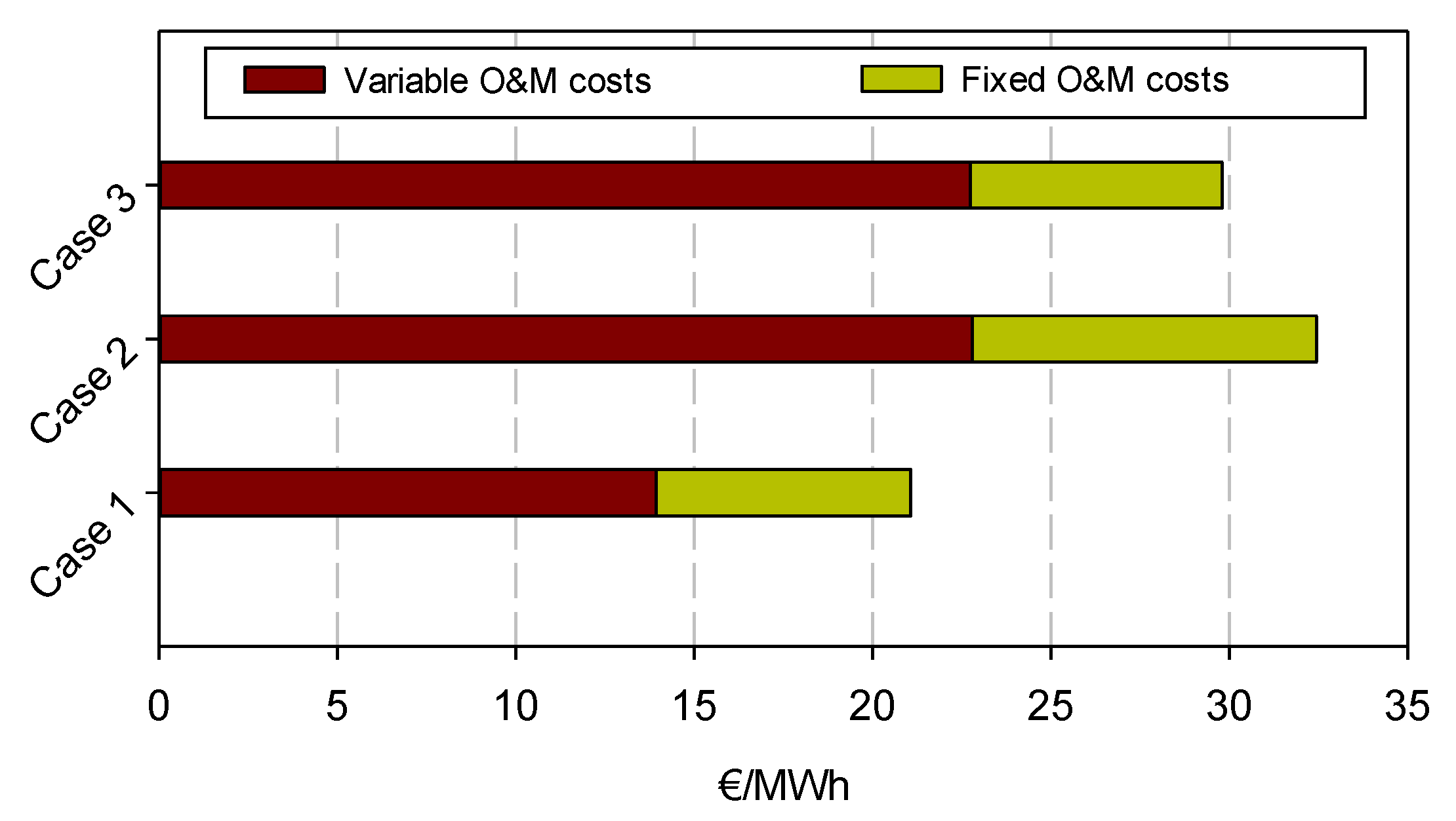
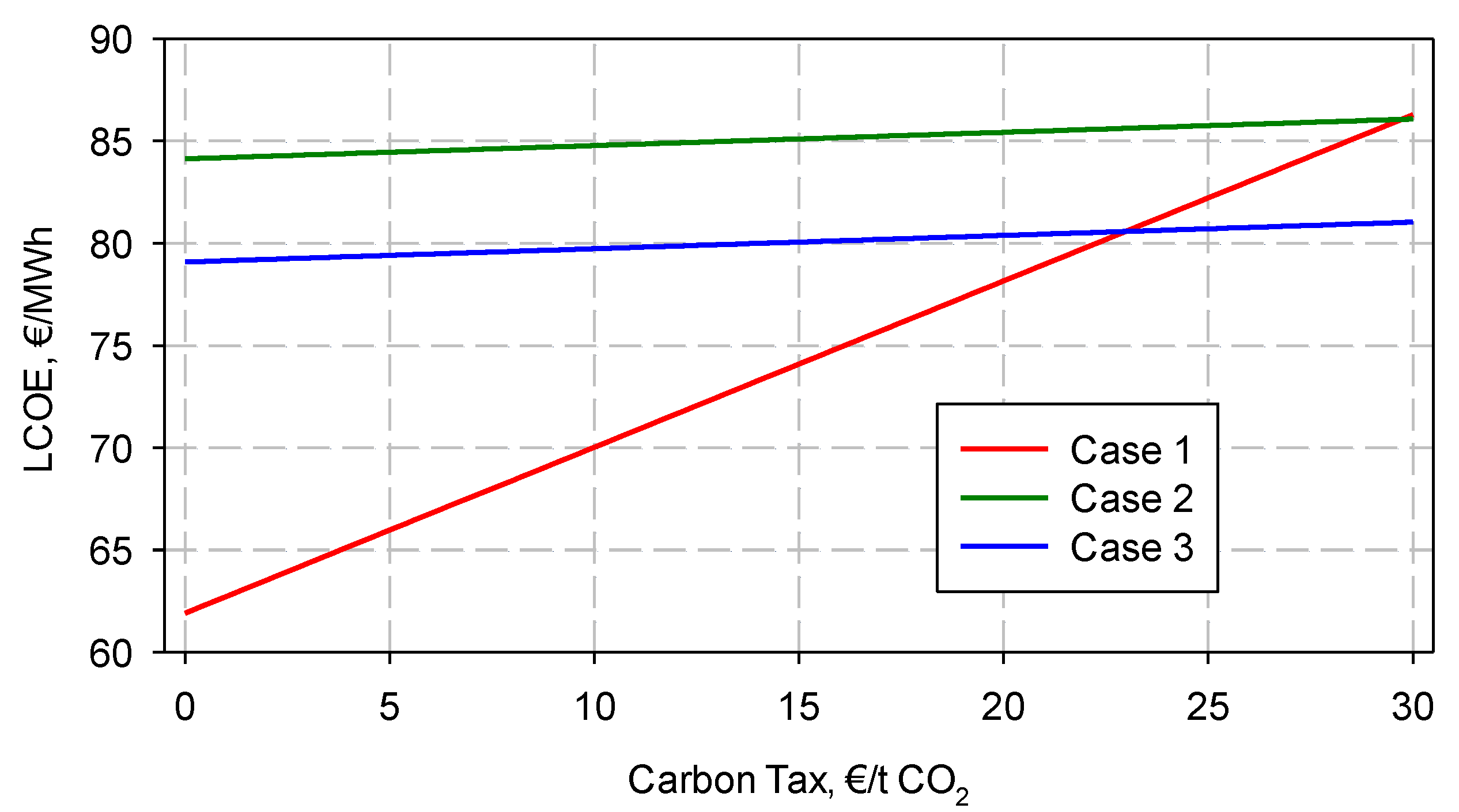
3.2. Estimation of O&M Costs, LCOE, and CO2 Capture Costs.

The O&M costs were evaluated separately as fixed and variable costs. The fixed costs, including taxes, insurance, administration, support, overhead costs, etc., are independent from the production, while the variable costs, such as fuel, waste disposal, consumables, CaL sorbent, etc., are proportional to power generation.
In Table 4, the main economic assumptions used for the evaluation of the O&M costs are reported [4,21,22,23,24,25,26], which were assessed with the Peters and Timmerhaus method [27]. Initially, the carbon tax was considered at no cost, but subsequently its effect was analyzed in depth.
Table 5 and Figure 1 show the distribution of the variable and total costs in €/MWh. As expected, particularly in the absence of a carbon tax, the lowest costs were registered by Case 1, both in terms of variable and fixed costs. It is clear that the presence of the CaL unit (Case 2) increases the annual maintenance costs and the variable costs, in particular those related to CO2 transport and storage; this results in an increase of fixed and variable costs of ca. 54%.
However, it is interesting to note that in Case 3, the utilization of the CaL unit for simultaneous CO2 and SO2 capture, with the consequent removal of the desulphurization unit, seems to have some advantages. The absence of one plant unit entails a diminishing of fixed costs; specifically, there is a reduction of maintenance costs related to the removal of the desulphurization unit. Case 3 shows a decrease of O&M costs of about 8% with respect to Case 2 and an increase of 41% with respect to Case 1.
The levelized cost of electricity (LCOE) and the cost of CO2 capture (in terms of CO2 removal cost) were evaluated as follows (according to [21,28,29]) and are presented in Table 6 for the three investigated cases:
L C O E = T I C × F C F + F O M W ˙ N E T × C F × 8670 + V O M + S F C η t h
C O 2   A v o i d e d   C o s t = L C O E w i t h   C C S L C O E w i t h o u t   C C S C O 2 e m i s s i o n s w i t h o u t   C C S C O 2 e m i s s i o n s w i t h   C C S
where TIC, VOM, FOM, SFC, and FCF are the total investment costs, the variable O&M costs, the fixed O&M costs, the specific fuel cost and the fixed charge factor respectively, while ηth, CF, and CO2 emissions are the thermal efficiency, the capacity factor, and the amount of emitted CO2, respectively.
The differences among the three cases investigated in terms of capital and O&M costs reflect the LCOE increase with respect Case 1 of 36% and 27% in Cases 2 and 3, respectively; this confirms the advantages of removing the desulphurization unit. In addition, regarding the avoided CO2 costs, Case 3 proves to be a better configuration than Case 2.
In Figure 2, the variation of LCOE as a function of the carbon tax for the three cases is shown. The increase of the carbon tax produces an increase of LCOE for all the three cases, but this increase is significant only for Case 1 because of the huge emissions of CO2. It is interesting to note that for equalizing the LCOE of Cases 1 and 2, the carbon tax must reach a value of 30 €/t CO2, while for Case 3, it is sufficient at 22.5 €/t CO2.

4. Discussion and Conclusions

In this work, the possibility of integrating the CaL unit in a pulverized fuel boiler power plant with the simultaneous capture of CO2 and SO2 was studied from a techno-economic point of view. Three cases were considered: Case 1 was a PF power plant without a CaL system and with SO2 abatement by wet scrubbing; Case 2 was a PF power plant with a CaL system and with SO2 abatement by wet scrubbing; and Case 3 was a PF power plant without the wet scrubber and with CaL used for simultaneous CO2 and SO2 capture.
From the analysis of the capital costs it was observed that the installation of the CaL unit inevitably involves an increase of the investment costs. However, the removal of the desulphurization unit somewhat limits this increase of capital costs. The O&M costs are negatively affected by the CaL unit, but the simultaneous capture of CO2 and SO2 (Case 3) is a valid strategy to limit the increased costs.
From the analysis of the LCOE, it was found that its value was strictly dependent on the possible regulations on greenhouse emissions (carbon tax). In particular, Case 3, where the CaL unit had the double task of capturing both CO2 and SO2, was shown to be a possible option to lower the impact of the CO2 capture system on the power plant’s costs.

Author Contributions

Conceptualization, F.S. and A.C.; methodology, A.C.; software, A.C.; formal analysis, A.C.; investigation, A.C.; data curation, A.C.; writing—original draft preparation, A.C.; writing—review and editing, F.S.; supervision, F.S. All authors have read and agreed to the published version of the manuscript.

Funding

This research received no external funding.

Acknowledgments

The authors wish to thank the students Ilaria Rabbito and Mario Perrotta (UniNa-Università degli Studi di Napoli Federico II) for their support in developing the techno-economic analysis.

Conflicts of Interest

The authors declare no conflict of interest.

References

  1. IEA. Energy and Climate Change, World Energy Outlook Special Report; IEA: Paris, France, 2015.
  2. Coppola, A.; Scala, F.; Salatino, P.; Montagnaro, F. Fluidized bed calcium looping cycles for CO2 capture under oxy-firing calcination conditions: Part 2. Assessment of dolomite vs. limestone. Chem. Eng. J. 2013, 231. [Google Scholar] [CrossRef]
  3. Zhao, C.; Chen, X.; Anthony, E.J.; Jiang, X.; Duan, L.; Wu, Y.; Dong, W.; Zhao, C. Capturing CO2 in flue gas from fossil fuel-fired power plants using dry regenerable alkali metal-based sorbent. Prog. Energy Combust. Sci. 2013, 39, 515–534. [Google Scholar] [CrossRef]
  4. Cormos, C.C. Economic evaluations of coal-based combustion and gasification power plants with post-combustion CO2 capture using calcium looping cycle. Energy 2014, 78, 665–673. [Google Scholar] [CrossRef]
  5. Pathi, S.K.; Lin, W.; Illerup, J.B.; Dam-Johansen, K.; Hjuler, K. Performance of a bench-scale fast fluidized bed carbonator. Energy Fuels 2014, 28, 5259–5269. [Google Scholar] [CrossRef]
  6. Ströhle, J.; Junk, M.; Kremer, J.; Galloy, A.; Epple, B. Carbonate looping experiments in a 1 MWth pilot plant and model validation. Fuel 2014, 127, 13–22. [Google Scholar] [CrossRef]
  7. Erans, M.; Manovic, V.; Anthony, E.J. Calcium looping sorbents for CO2 capture. Appl. Energy 2016, 180, 722–742. [Google Scholar] [CrossRef] [Green Version]
  8. Li, Z.; Wang, Y.; Li, Z.; Li, M.; Xu, K.; Liu, W.; Luo, G.; Yao, H. Limestone Decomposition in an O2/CO2/Steam Atmosphere Integrated with Coal Combustion. Energy Fuels 2016, 30, 5092–5100. [Google Scholar] [CrossRef]
  9. Perejón, A.; Romeo, L.M.; Lara, Y.; Lisbona, P.; Martínez, A.; Valverde, J.M. The Calcium-Looping technology for CO2 capture: On the important roles of energy integration and sorbent behavior. Appl. Energy 2016, 162, 787–807. [Google Scholar] [CrossRef] [Green Version]
  10. Salaudeen, S.A.; Acharya, B.; Dutta, A. CaO-based CO2 sorbents: A review on screening, enhancement, cyclic stability, regeneration and kinetics modelling. J. CO2 Util. 2018, 23, 179–199. [Google Scholar] [CrossRef]
  11. Tregambi, C.; Montagnaro, F.; Salatino, P.; Solimene, R. A model of integrated calcium looping for CO2 capture and concentrated solar power. Sol. Energy 2015, 120, 208–220. [Google Scholar] [CrossRef]
  12. Tregambi, C.; Salatino, P.; Solimene, R.; Montagnaro, F. An experimental characterization of Calcium Looping integrated with concentrated solar power. Chem. Eng. J. 2018, 331, 794–802. [Google Scholar] [CrossRef]
  13. Coppola, A.; Esposito, A.; Montagnaro, F.; De Tommaso, G.; Scala, F.; Salatino, P. Effect of exposure to SO2 and H2O during the carbonation stage of fluidised bed calcium looping on the performance of sorbents of different nature. Chem. Eng. J. 2019, 377, 120626. [Google Scholar] [CrossRef]
  14. IEA-GHG. Improvements in Power Generation with Post-Combustion Capture of CO2. Report PH4/33, Nov. 2004; IEA Greenhouse Gas R&D Programme: Cheltenham, UK, 2004.
  15. Xu, G.; Yang Y ping Ding, J.; Li, S.; Liu, W.; Zhang, K. Analysis and optimization of CO2 capture in an existing coal-fired power plant in China. Energy 2013, 58, 117–127. [Google Scholar] [CrossRef]
  16. Petrescu, L.; Bonalumi, D.; Valenti, G.; Cormos, A.M.; Cormos, C.C. Life Cycle Assessment for supercritical pulverized coal power plants with post-combustion carbon capture and storage. J. Clean. Prod. 2017, 157, 10–21. [Google Scholar] [CrossRef]
  17. Turton, R.; Bailie, R.C.; Whiting, W.B.; Shaeiwitz, J.A. Analysis, Synthesis and Design of Chemical Processes; Pearson Education: London, UK, 2008. [Google Scholar]
  18. Cormos, C.C. Techno-economic and environmental evaluations of large scale gasification-based CCS project in Romania. Int. J. Hydrog. Energy 2014, 39, 13–27. [Google Scholar] [CrossRef]
  19. Romano, M.C.; Spinelli, M.; Campanari, S.; Consonni, S.; Cinti, G.; Marchi, M.; Borgarello, E. The calcium looping process for low CO2 emission cement and power. Energy Procedia 2013, 37, 7091–7099. [Google Scholar] [CrossRef] [Green Version]
  20. Cormos, C.C.; Vatopoulos, K.; Tzimas, E. Assessment of the consumption of water and construction materials in state-of-the-art fossil fuel power generation technologies involving CO2 capture. Energy 2013, 51, 37–49. [Google Scholar] [CrossRef]
  21. Yang, Y.; Zhai, R.; Duan, L.; Kavosh, M.; Patchigolla, K.; Oakey, J. Integration and evaluation of a power plant with a CaO-based CO2 capture system. Int. J. Greenh. Gas Control 2010, 4, 603–612. [Google Scholar] [CrossRef]
  22. Martínez, A.; Lara, Y.; Lisbona, P.; Romeo, L.M. Operation of a mixing seal valve in calcium looping for CO2 capture. Energy Fuels 2014, 28, 2059–2068. [Google Scholar] [CrossRef]
  23. Romano, M.C.; Martínez, I.; Murillo, R.; Arstad, B.; Blom, R.; Ozcan, D.C.; Ahn, H.; Brandani, S. Process simulation of Ca-looping processes: Review and guidelines. Energy Procedia 2013, 37, 142–150. [Google Scholar] [CrossRef]
  24. Mantripragada, H.C.; Rubin, E.S. Calcium looping cycle for CO2 capture: Performance, cost and feasibility analysis. Energy Procedia 2014, 63, 2199–2206. [Google Scholar] [CrossRef] [Green Version]
  25. Hanak, D.P.; Powell, D.; Manovic, V. Techno-economic analysis of oxy-combustion coal-fired power plant with cryogenic oxygen storage. Appl. Energy 2017, 191, 193–203. [Google Scholar] [CrossRef] [Green Version]
  26. Erans, M.; Hanak, D.P.; Mir, J.; Anthony, E.J.; Manovic, V. Process modelling and techno-economic analysis of natural gas combined cycle integrated with calcium looping. Therm. Sci. 2016, 20, S59–S67. [Google Scholar] [CrossRef] [Green Version]
  27. Peters, M.S.; Timmerhaus, K.D.; West, R.E.; Timmerhaus, K.; West, R. Plant Design and Economics for Chemical Engineers; McGraw-Hill: New York, NY, USA, 1968; Volume 4. [Google Scholar]
  28. Abanades, J.C.; Grasa, G.; Alonso, M.; Rodriguez, N.; Anthony, E.J.; Romeo, L.M. Cost structure of a postcombustion CO2 capture system using CaO. Environ. Sci. Technol. 2007, 41, 5523–5527. [Google Scholar] [CrossRef] [PubMed] [Green Version]
  29. Zhao, M.; Minett, A.I.; Harris, A.T. A review of techno-economic models for the retrofitting of conventional pulverised-coal power plants for post-combustion capture (PCC) of CO2. Energy Environ. Sci. 2013, 6, 25–40. [Google Scholar] [CrossRef]
Figure 1. O&M costs.
Energies 13 02176 g001
Figure 2. Effect of the change in carbon tax on LCOE.
Energies 13 02176 g002
Table 1. Main design characteristics of the power plant and of the CaL unit (adapted from [4]).
UnitParameters
BoilerPulverized fuel boiler
Air separation unit95% (vol.) oxygen purity
(Consumption: 200 kWh per tons of oxygen)
Desulphurisation unitLimestone Flue-gas desulfurization
(SO2 abatement efficiency: 98–99%)
Calcium looping unitCarbonation @650 °C–Calcination @940 °C
Sorbent make-up ratio: 5%
Captured CO2 conditioningIntercooled multi-stage compression @120 bar
Dehydration by Tri-ethylene-glycol
Steam cycleSub-critical: 170 bar@540 °C–
One re-heat: 39 bar@540 °C
Table 2. Main technical power plant performance indicators (adapted from [4]).
Main Plant DataUnitsCase 1Case 2Case 3
Coal flowratet/h182.30242.30246.97
Coal LHVMJ/Kg25.1725.1725.17
Fuel thermal energyMWth1274.581694.081726.73
Gross power outputMWe504.28658.80670.83
ASU consumptionMWe0.0025.7626.23
Boiler consumptionMWe6.378.478.63
Ca-looping unit consumptionMWe-56.0057.02
Power island consumptionMWe22.6923.6423.71
Ancillary consumptionMWe29.07113.87115.60
Net power outputMWe475.21544.93555.23
Gross efficiency%39.5638.8938.85
Net efficiency%37.2832.1732.15
Carbon capture rate%-92.0092.00
CO2 specific emissionsKg/MWh931.0374.4874.48
Table 3. Estimation of capital costs and total investment cost per kW.
Plant Sub-UnitsUnitsCase 1Case 2Case 3
equipment cost (EC)Solid handling facilitiesM€46.1057.3960.26[20]
Air separation unitM€0.00102.65107.78[20]
BoilerM€180.16180.16180.16[20]
CaL unitM€0.0092.7097.34[19]
Sulphur removal unitM€78.16100.380.00[20]
CO₂ processing and dryingM€0.0033.1433.14[20]
Power islandM€133.71166.73150.06[20]
Utilities and offsite units (U&O)M€109.53183.29157.1925% of EC
Total installed costs (IC)M€547.66916.44785.93EC + U&O
Owner’s costs and contingency (O&C)M€82.15137.47117.8915% of IC
Land, permitting, surveying, etc. (L)M€27.3845.8239.305% of IC
Total investment costs (TIC)M€657.201099.73943.11IC + O&C + L
TIC per KW (gross)€/kW1303.231620.511389.74
TIC per KW (net)€/kW1382.941957.121678.41
Table 4. Basic economic assumptions for calculation of operation and maintenance (O&M) costs.
Coal1.9€/GJ
Limestone (flux)20€/t
Natural gas cost5€/GJ
BFW and process water price0.1€/t
Cooling water price0.01€/t
Make up and water treatment chemicals0.0025€/t
Slag disposal cost10€/t
CO₂ transport and storage costs5€/t CO₂
Carbon tax0€/t CO₂
Direct labor100persons
Average annual direct labor costs50000€/y
Administrative, support, and overhead costs30% of the direct labor cost0.3
Annual maintenance costs3.5% from capital expenditure (CAPEX)0.035
Working capital30-day supply
Power plant load factor7500h/y
Construction time3year
Economical plant life25year
Discount rate8.00%
Table 5. Fixed and variable costs in M€/y.
Case 1Case 2Case 3
Supervision 1.7501.7501.750
Cost of direct labor5.0005.0005.000
Maintenance25.29734.99530.000
Taxes and insurance5.0596.9996.000
Total Fixed Costs37.10648.74442.750
Coal65.61886.92288.582
Limestone make-up2.34627.99029.274
Cooling water0.0040.0060.006
Spent limestone disposal 0.0008.70510.487
Gypsum disposal0.6950.8800.000
Ash disposal4.4145.5875.671
CO₂ transport and storage0.00021.91922.733
Total Variable Costs73.078152.009156.753
Table 6. Levelized cost of electricity and avoided CO2 costs.
UnitsCase 1Case 2Case 3
LCOE€/MWh61.9084.1379.09
CO2 avoided cost€/t CO2025.9520.06

