1. Introduction
The transition from the conventional electricity grid towards the ‘smart grid’ has introduced continuous advancements in the electrical network infrastructure (e.g., the large integration of distributed generation units, new grid interconnections, and energy islands) and the constant deployment of new emerging monitoring, communication, computation, and control technologies in order to enhance grid stability, reliability, resilience, and efficiency. It is therefore evident that the design and analysis of the smart electricity grid cannot be performed without taking into account the interaction between the physical network infrastructure (physical layer) and the information, communication, sensing, and control systems (cyber layer), hence introducing the need for a cyber–physical systems (CPS) perspective in modern electricity grids [
1,
2,
3,
4,
5,
6,
7]. The complexity of the CPS-based design of the smart grid further increases with the integration of market, policy, and regulation authorities; the social network characteristics and needs of active power consumers/producers; and the environmental factors, all of which affect the behavior, performance, and efficiency of the entire network [
1,
8].
Due to the integration of multiple heterogeneous players and factors (from users and key stakeholders to distributed energy resources, devices, and decision-making tools) within the smart grid architecture, government bodies and policy-regulation authorities have expressed an interest in a whole-system approach in modern power networks in order to capture the complex interaction across different layers (engineering, societal, environmental, and business). For example, the UK Government’s Clean Growth Strategy and National Grid have highlighted how a whole system view of the electricity industry can significantly increase the consumer and societal value [
9]. In this framework, the CPS perspective in smart grids can be utilized to analyze how a change/modification or a decision made in the physical world affects the operation of the cyber world and vice versa. Hence, it can capture the dynamic interactions between heterogeneous components within a given layer, e.g., between different structures and operating principles introduced by distributed energy resources (DERs), as well as the cross-layer interactions between the different components, systems, and architectures, i.e., linking the physical system units with the control and communication mechanisms. In this framework, a CPS approach to the smart electric power grid was provided in [
10], where a series of modelling and decision-support tools for DERs in a smart grid infrastructure were presented, together with advanced communication, control, and cybersecurity mechanisms. Depending on the power system architecture under consideration, there have been several approaches to CPS design. For example, in local energy systems or micro-grids, a CPS-based approach has been proposed to investigate intelligent micro-grid modelling and control aspects [
11,
12,
13], micro-grid system security and resilience [
14,
15], and the development of real-time co-simulation testbeds [
16,
17].
Similarly, a CPS-based review of models and methodologies for smart grids can be found in [
18]. Complex network theory provides a powerful tool in modelling the different CPS layers and their interactions, e.g., they can be used to analyze the effects of cyberattacks or how cascading failures progress from the cyber to the physical layer and vice versa [
8,
19]. Cyberattacks result in compromised measurement signals from sensors or control signals from actuators, e.g., via communication package losses, creating the need for attack-resilient power systems through the development of novel cybersecurity methods and technologies [
20,
21]. The control and measurement signals close the loop between the cyber and the physical layers, thus representing the key technologies for achieving a stable, reliable, and resilient CPS-based power system architecture [
22,
23]. In this framework, the development of different computing methodologies, e.g., adaptive real-time scheduling [
24] or novel hierarchical control techniques for power systems (from micro-grids to power distribution and transmission systems) [
25,
26,
27], are active areas of research in modern power systems in order to analyze the multiple layers of the CPS framework.
Overall, the CPS approach can assist researchers in developing basic technological tools related to network deployment, system modeling and analysis, communication, cloud-fog computing, big/smart data, industrial automation, Internet of Things/Systems (IoT/IoS), optimization and algorithms, industrial and advanced intelligent-based control, security, etc. This scheme has, in its core, the integration and connectivity of operation technology (OT) and information technology (IT). OT supports the physical and manufacturing processes of devices, sensors and software necessary to control and monitor plants and devices, and, on the other hand, IT combines all the particular technologies for information processing. Instead of managing OT and IT as two different domains, the synergetic operation of these two technologies can bring clear advantages [
8,
10], such as the task of enhanced system performance at the dynamic and steady-state level, gains in stability, flexibility and reliability, reductions on cost and risk, and optimizations in short and long term scheduling. For a large-scale system, as it can be found in the future smart electricity grid, such a CPS approach that captures, identifies, and explains the dynamics of the physical and cyber parts, as well as their interaction and integration, will provide the necessary tools to bridge the gap between power engineering, systems engineering, and computer science researchers.
The aim of this paper is to provide a framework for investigating the cyber–physical architecture of modern electricity grids and capturing the integration and interaction between the complex layers of the cyber and physical worlds. After defining the CPS framework, it is explained how different levels of the CPS-based architecture can be analyzed, highlighting the typical assumptions made in order to make this analysis feasible, while a detailed modelling of the dynamic interaction between the physical and cyber system is also presented. It is expected that the CPS approach provided in this paper will contribute to the current effort made by recent researchers and industrialists of investigating and analyzing the complex smart electricity grid, offering the necessary modelling tools and interaction functions to link the physical and the cyber layers. Since the proposed CPS design only provides a framework for investigating future large-scale smart electricity grids, in order to assist towards this goal, an example of a CPS-based industrial micro-grid system that currently exists in the UK is presented at the end of this paper to assist the readers in visualizing the CPS design and approach, even at a local smart energy system architecture.
The remainder of the paper is structured as follows. In
Section 2, the proposed CPS framework for modern electricity grids is presented in detail. In
Section 3, a step-by-step analysis of the different levels of the CPS approach is provided together with the common modelling tools and assumptions that are required. In
Section 4, the example of an industrial micro-grid viewed as a CPS design is explained, while in
Section 5, the conclusions of the paper are drawn.
2. Cyber–Physical Framework for Modern Power Systems
A CPS-based framework for the smart grid architecture can be used to capture the key devices, components, users, and their interaction in modern electricity grids—thus visualizing the integration between power systems, communication, sensing, and actuation systems. Such a framework can provide the required guidance to researchers, industrialists, and key stakeholders on how to analyze each layer of the CPS architecture in terms of system modelling, dynamics, control, monitoring, information gathering, analysis, and exchange to achieve the required grid stability, reliability, resilience, and energy efficiency. However, the heterogeneity between the different components and the multiple factors (environmental, economic, and social) that have been introduced in the modern smart grid architecture has significantly increased the complexity of the CPS-based design and analysis. Here, a method for integrating modern electricity grids into a CPS framework is presented to clearly illustrate the interaction/integration between the physical and cyber layers from a system modelling and actuation point of view to facilitate the dynamic analysis and decision-making procedures and actions at each level of the CPS-based hierarchical structure. This CPS framework is depicted in
Figure 1.
The physical system architecture of this CPS framework comprises of different layers, each one represented by a larger set that either incorporates or directly interacts with the smaller ones. In particular, as shown in the right side of
Figure 1, the first and smaller set includes the devices and individual components of the power system, such as distributed generation units (conventional, renewables, storage, etc.), locally controlled power electronic devices, and responsive/non-responsive loads together with their sensing, monitoring, protection and communication mechanisms. This is a key layer in the CPS design since every action/decision obtained at any level of the decision-making hierarchy is eventually implemented on the physical system through these power devices/units. Therefore, these devices represent the active components of the physical system in the modern power grid infrastructure.
The second layer introduces the network infrastructure, i.e., the distribution, transmission lines, and interconnections (AC, HVDC), describing the network architecture, i.e., how individual devices of the first layer are connected together, enabling the dynamic interaction between the heterogeneous components. Then, the market layer is formed that describes the economic factors that are linked with the energy infrastructure, i.e., the energy market and energy transactions at a local, regional, national, and international scales, that are implemented through the electricity network and play the key role in optimizing energy efficiency in the current and future electricity grid.
Finally, the layer that introduces the users is formed; these users can be energy producers, consumers, prosumers (both producers and consumers), key stakeholders and grid operators (e.g., transmission system operator (TSO), distribution system operator (DSO), independent distribution network operator (IDNO)). This layer illustrates their interactions though social relations and online market operations that are implemented in the actual electricity grid via human–machine interface (HMI) devices and tools. The top two layers are often affected by environmental and geographical factors that continuously update the market mechanisms and the social behavior and enable the aggregation of multiple clean energy producers to achieve maximum decarbonization.
The cyber system architecture of the CPS framework incorporates the data gathering, analysis, communication, and control actions that are applied on the physical system to enhance the intelligence of the power system. In particular, as it can be seen in
Figure 1, data and information from the different layers (from the energy units and devices to the market and social mechanisms) are collected through measurement tools and data acquisition technologies to the cyber network that may include cloud/fog computing and IoT tools via suitable communication protocols, following the necessary security and privacy requirements. This information can be either processed by a central processing unit or directly transferred to the corresponding level of hierarchical action that is shown at the left side of
Figure 1. In large-scale power networks with a high number of units, devices, users, stakeholders, etc., the data sets gathered are too large and too complex to be handled by a typical processing unit, leading to the challenges of the recent and well-known field of ‘big data.’ For example, although smart meter deployment has begun and is expected to significantly increase in the following years, utility industries are faced with major challenges on how to deal with the large volume of data (scale of petabytes) that often has to be stored for several years. Research in this area is currently ongoing and includes, among others, methods and technologies for data capturing, storage, analysis, privacy, and prediction [
28,
29].
Due to the continuously evolving nature of the smart grid, there is an emerging need for flexible, secure, and reliable communication and data analysis architecture that allows for a scalable deployment of communication devices. Fog computing/networking, which supports the IoT concept, can provide a flexible solution since it enables data storage, analysis, and communication to be conducted at a local scale. For example, in local energy systems or micro-grids, messaging-based flexible fog computing can be used to allow for resource deployment at different points of the system without affecting their functionality or integrity [
30,
31]. Messaging brokers can be used to translate industrial communication protocols (e.g., CAN and Modbus) to open standard application layer protocols, such as AMQP, and vice versa for control, actuation, or other sensing requirements, thus minimizing the need for system reconfiguration. Hence, a secure, reliable, and flexible centralized or distributed communication network architecture is essential for the cyber system in order to link the physical world devices with the necessary control actions that optimize the electricity grid operation in the frame of a connective OT/IT implementation.
The key control actions and decisions made in modern power systems that are responsible for the ‘smartness’ of the electricity grid and are found at the core of the cyber part of the CPS architecture are represented in a hierarchical structure, as shown at the left side of
Figure 1. The hierarchical nature indicates the interactions between the different control layers, from unit-level/primary control, though supervisory control and optimization design, to energy planning and policy, and this nature presented in this sequence to illustrate: (i) the necessary set of actions that correspond to the different layers of the physical system, (ii) the different data size and communication links required to make these decisions, depending on the decentralized, distributed, or centralized control design, and (iii) the different time scales for the control actions. Nevertheless, it is worth noting that as one considers the control unit actions from the primary level to the upper levels of supervisory, economic, and planning, a clearly different time horizon has to be taken into account for the system response. All transients with time response usually less than a second are performed in the primary control level, and this is one of the reasons that this level is actually a part of the physical system since it is designed to confront large disturbances or emergency situations immediately after they occur by feeding back local measurement signals. At normal situations, their command inputs—
A1 settings—are changed in accordance to the upper levels decisions. The time horizon is gradually expanded to several seconds, minutes, hours, and much more time domains at every upper level action. This, however, may lead to the appearance of time delays in the upper-level loops. Due to stability reasons, these need to be bounded in a domain smaller than the maximum time horizon of the corresponding level (see
Section 3.3 and the references therein).
The unit-level/primary control represents a completely decentralized operation where information is only collected from the individual energy resources and devices (local power, current, voltage, frequency, etc.) and is implemented at the corresponding actuation units at a time scale of a few ms. These are the key control actions responsible for stabilizing the electricity grid according to grid code requirements [
32].
Supervisory control is designed to improve grid efficiency by maintaining or restoring grid frequency and voltage to the nominal/rated values and is often implemented in a distributed manner by only collecting information from neighboring energy resources to enable plug-and-play operation with a time constant of few seconds or minutes [
33,
34,
35]. The economic operation and power system optimization, together with the energy planning and policy layers, operate every few hours up to several days (with an increasing interest in minimizing these time scales), and require much more data that correspond to larger areas of the power network and are utilized in a centralized control operation that affects the electricity market mechanisms and the social mechanisms, respectively.
The interactions between the different control layers in
Figure 1 are represented by actuation and feedback signals denoted as
A1,
A2,
B1,
B2,
C1, and
C2. Particularly, indicates the local settings, e.g., correction terms for the voltage and frequency restoration, that correspond to each individual energy resource unit and are eventually implemented through primary control. Subsequently, represents the local feedback that is fed from the primary to the supervisory control and can be present in cases where the dynamic state of the unit-level control is required for the distributed control implementation at the immediate upper level. Variable indicates the power demands, i.e., reference power values, for an individual or a group of energy resources that have resulted as the solution of the energy/economic optimization problem to suitably inject or draw power from each unit. At the same time, the feedback signal includes technical constraints from either the network or the energy resources, e.g., power flow limits, battery operation, and lifetime requirements, that are incorporated into the optimization problem. Finally, the arrow illustrates the energy policy decisions that are fed into the economic operation, while represents the incentive tools and mechanisms that are required to update the energy planning, together with the policy and regulations. It is clear that in all the distinct levels of the supervisory control, local decentralized computing is implemented to realize the particular interacting procedures.
As a result, it becomes clear that the CPS perspective presented in this paper demonstrates the clear integration and interaction between the different layers of the physical and cyber parts of modern power systems, all of which introduce high complexity and heterogeneity. Though the analysis of the entire CPS architecture seems as a daunting task, the proposed framework that is presented in
Figure 1 provides the opportunity of simultaneously analyzing both the cyber and the physical system dynamics of each layer in order to capture the interaction between the control and communication with the physical plant, as well as the interaction between the lower and the higher levels of the hierarchy in analytical–mathematical manner. This is provided and clarified in the sequel sections.
3. Cyber–Physical System Analysis
In order to clearly describe a framework that can be used to analyze the dynamic interactions taking place within a modern power system, the investigation starts from the lower to the higher levels of the CPS-based design.
3.1. Energy Resources and Primary Control Design and Analysis
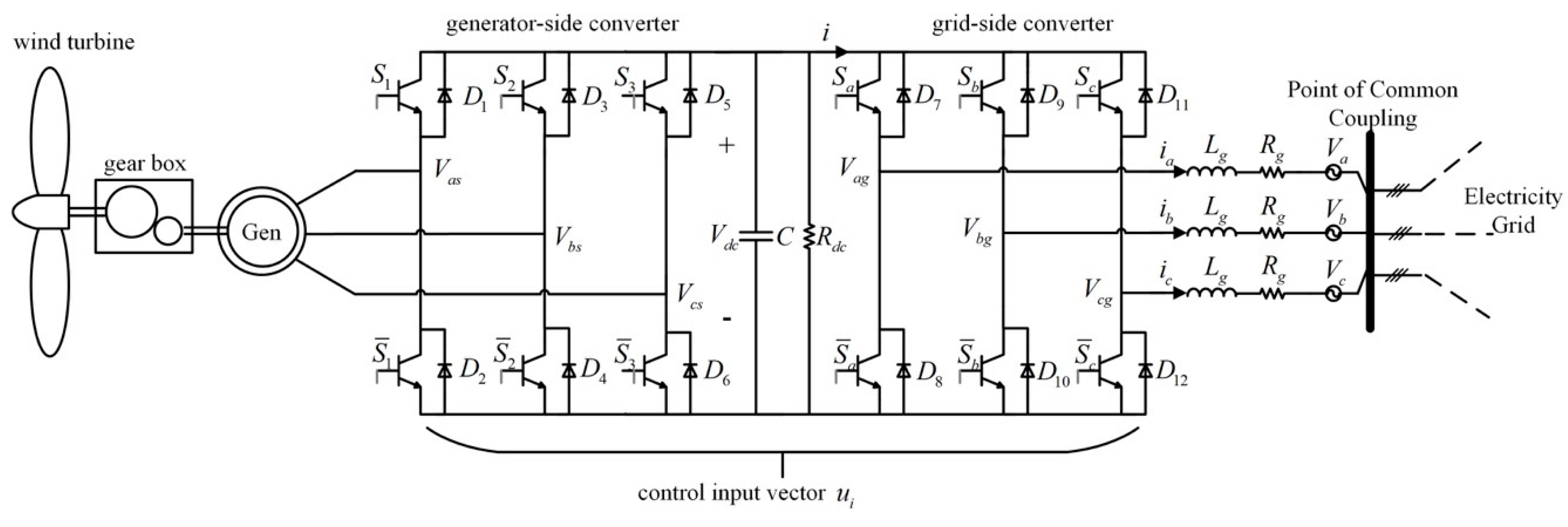
The energy resources, e.g., conventional generators, distributed generation, storage units, renewables, and responsive loads, sit at the heart of the electricity grid infrastructure and represent the active-controllable components of the power network. The majority of these units are integrated to the grid via electromechanical systems (generators and machines) or power electronic devices that represent their controllable interface components.
Figure 2 shows an example of a power electronic converter unit used to integrate a renewable energy unit with the main grid. Here, a wind turbine (WT) generator connected to a point of the grid through a back-to-back AC/DC/AC converter is considered as a representative example since its model includes the electromechanical components of the WT and the generator together with the converter and line filter dynamics. In principle, the dynamic analysis of every grid-connected energy unit can be independently investigated and be represented by nonlinear dynamic equations, due to the nonlinearities introduced by the power electronics or the electromechanical systems, as:
where
represents the state vector of the
i-th energy resource unit;
is the control input vector, often described by the controllable elements of the power converter, e.g., duty-ratio components and voltages; and
represents external inputs of disturbances (e.g., grid voltage and mechanical torque).
In order to link the elements of Equation (1) with the main
Figure 1, it is underlined that and indicate the output and input signal, respectively, of the energy resources and devices block connected to the unit-level/primary control block. The system dynamics given by Equation (1) can be expressed in the dissipative-Hamiltonian or port-controlled Hamiltonian forms [
36,
37,
38] to enable the design of stabilizing controllers and also to provide an easy way of expressing the units interconnections that are represented at the higher level of the physical system (electrical network).
Every energy resource unit is equipped with a dedicated controller, usually a microcontroller device, implementing the unit-level or primary control (
Figure 1) that operates in a completely decentralized manner, i.e., requires only local information from the particular energy unit [
39]. The aim of this control scheme is to achieve accurate real and/or reactive power regulation, often through inner voltage and current control loops (cascaded control), or to provide ancillary services to the grid through voltage and frequency support (droop control and virtual synchronous generator). The latter implies that the injected real and reactive power from each distributed generation unit is adjusted accordingly to assist in the regulation of the grid voltage and frequency. Hence, the control dynamics can be expressed in the generic form:
which can be either static (including only term
, i.e.,
) or dynamic with the addition of the control state vector
. Note that
represents the desired signals or correction terms that are obtained from the supervisory control (notation
in
Figure 1). The primary control dynamics Equations (1) and (2) correspond to linear (usually PID controllers) [
40] or nonlinear control techniques [
41,
42] in a single or cascaded control structure [
43].
The physical devices, together with the primary control design, represent the most crucial components of the CPS-based power system since they represent the main link between the cyber and the physical system; this is because every decision/action that is taken at any level of the hierarchical control structure is finally implemented to the physical infrastructure through the energy resource units and devices. Hence, the stable and reliable operation of the power system depends on the primary control and the energy units dynamics. In order to analyze this particular layer of the CPS architecture, some of the key assumptions often made by grid operators, researchers and industrial engineers include:
Each individual energy resource unit is connected to a point of common coupling of a relatively stiff grid (grid voltage and frequency are considered constant); thus, each unit’s dynamics are decoupled with respect to their neighbors.
Environmental and social factors do not affect the system dynamics due to their slow variations with respect to the fast electrical devices.
The reference signals obtained from the supervisory control level are assumed to be constant due to the different time scales between the primary and the supervisory control design.
Under these assumptions, the stability analysis of the physical and cyber system dynamics can be conducted mainly using linearization and small-signal modelling [
44] and also using advanced nonlinear theoretic tools to accurately capture the nonlinear phenomena and dynamics of both the physical plant and the primary controller [
45,
46,
47].
3.2. Electrical Network and Supervisory Control Design and Analysis
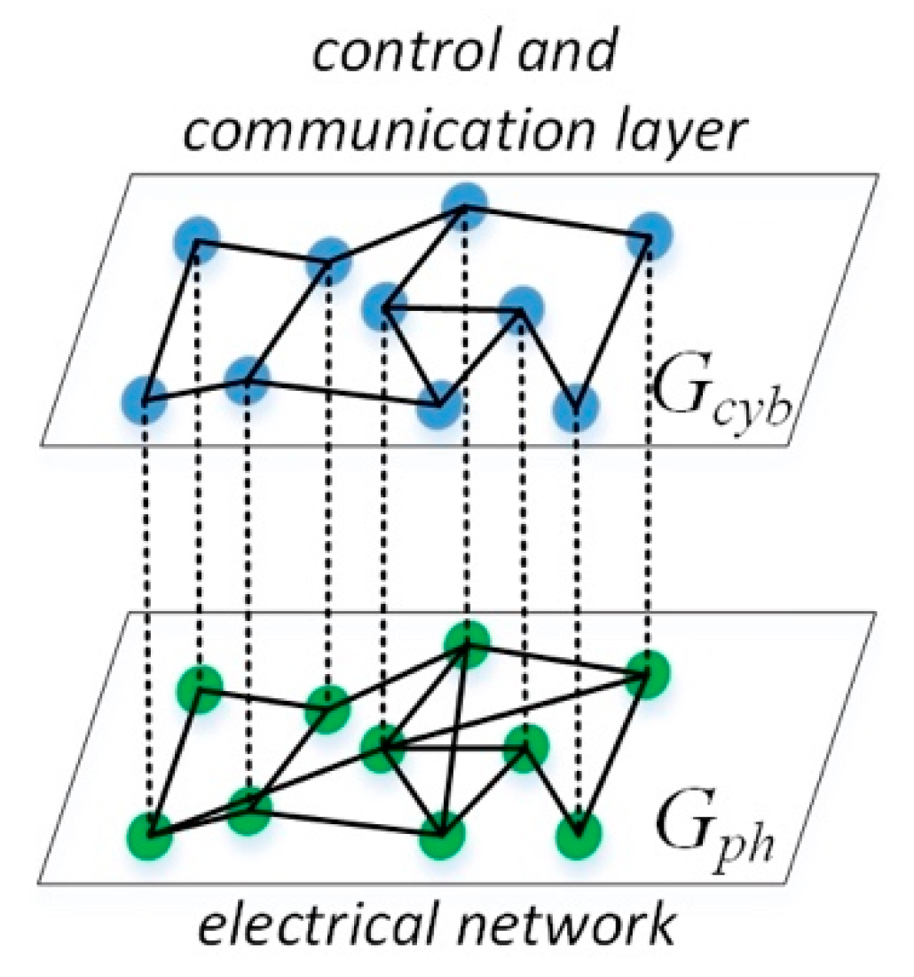
Though the analysis and primary control design for individual devices are essential for each unit’s desired and stable operation, the optimal and efficient performance of the electrical grid lies on the interaction of multiple energy resources within the electrical network. It is therefore evident that their dynamic interaction, both at the physical and at the cyber layers, should be analyzed. This can be conducted using the multi-layered architecture and algebraic graph theory, as described in [
8,
40], and it is depicted in
Figure 3.
In particular, the physical electrical network can be represented by an undirected and connected graph
, where
is the set of
nodes (each one of them representing a DER unit or load of the network) and
is the set of
edges, indicating the links between DER units and loads within the electrical network. For the dynamic representation of the electrical network, the following assumptions are usually made [
33,
48]:
Given that the electrical network is described by the undirected graph , the incidence matrix of the system can be obtained by considering an arbitrary direction to each edge. The elements of the i-th row of are either 1 or -1 when i is a source or sink, respectively, of the directed edge , where belongs to the neighborhood of node i, i.e., ; otherwise, the corresponding element is zero.
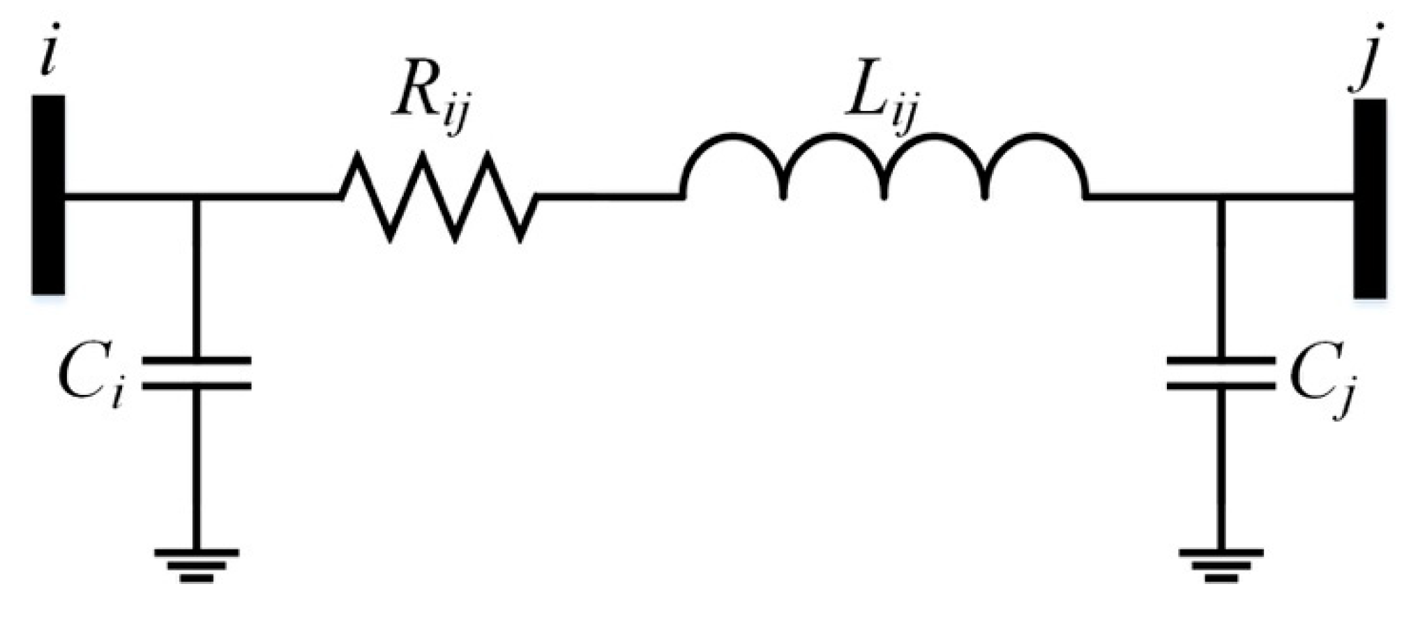
Now, from
Figure 4, let the matrices
,
,
, and
, where
represents the shunt conductance of the
i-th node (if it exists; otherwise
). The dynamic equations that represent the network can be now expressed as [
48]:
where
V is the vector of the node voltages,
I is the vector of edge (equivalently line) currents, and
is the vector including the constant current injected by a DER unit or drawn by a load of the network. An equivalent representation can be obtained by assuming constant voltage or power sources/sinks. It is worth noting that in the cases of low voltage AC electrical networks or DC networks (e.g., DC micro-grids), the inductance
of each line is neglected, and, therefore, Equation (4) becomes:
as analytically explained in [
48]. Here,
represents the symmetric Laplacian matrix associated with graph
. Note that a special case of the DC network, consisting of parallel DER units connected to a common load, is often considered in islanded systems [
49].
In a similar framework, the control and communication layer of
Figure 3 can be also represented by an undirected and connected graph
, where
is the set of
nodes (each one of them representing the supervisory control action taken by a DER unit or controllable load of the network) and
is the set of
edges (indicating the communication links of neighboring DERs) that are used for the information exchange. Note that in several studies, the physical
and cyber
graphs coincide under the assumption that all DERs and loads of the network are controllable and
, where
. However, this might not be true in a real system where, for example, some DERs/loads do not participate in the supervisory control
or when
, which indicates the case where a DER unit
i might interact with DER unit
j at the physical layer but not at the cyber layer.
Though several control methods have been designed for the supervisory control of modern power systems (centralized/distributed), recent trends have focused on distributed control where information is exchanged only among units
i and
j where
. One of the most common distributed control methods lies on the consensus-based control approach and takes the following dynamic form:
with
being the vector of desired signals or correction terms that are fed into the primary controller given in Equations (2) and (3), where
includes the voltage
and/or the line currents
of the lines linked to the
i-the unit, while
is the vector of desired signals inserted from the economic operation and optimization design. The loop between the physical system dynamics given in Equation (4), equipped with the primary controller, i.e., Equations (2) and (3) and the supervisory dynamics, i.e., Equation (5), is achieved by considering that the control input of the physical system is the current source/sink vector
of each DER unit, i.e.,
in Equation (2).
The control and communication graph
is often assumed to be weighted, i.e., the adjacency matrix
is introduced with elements
when
; otherwise,
, representing the weights of the communication links. Hence, the Laplacian matrix
is obtained as
(where
is the diagonal matrix with diagonal terms the elements of vector
) and can differ from
as explained above. In order to further explain why Equation (5) represents a distributed controller via the Laplacian matrix
, each row of Equation (5) that corresponds to the control action of the
i-th DER unit can be analytically written as:
where
. For example, in scenarios of stand-alone power networks (e.g., islanded microgrids) where accurate power sharing is required among the DER units and voltage/frequency restoration, the terms
and
represent functions of the (measured and desired) power injected/drawn by the
i-th and
j-the unit, respectively, while
is a function responsible for restoring the voltage/frequency to the rated values.
It should be highlighted that the presented framework that describes the supervisory control design and its interaction with the physical system can be also useful when investigating abnormal conditions where units are disconnected or when there are losses of communication links. In the latter case, the graph might not be connected anymore, and further analysis is required to guarantee the stability and resilience of the CPS-based power system that has to be conducted on a case-by-case basis.
3.3. Economic Operation/Optimization and Electricity Market
The next layer of the CPS-based hierarchical approach introduces the integration and interaction between the market operation and mechanisms with the electrical network. The structure of the market dynamics varies from local energy transactions and peer-to-peer (P2P) energy trading to national and international market operation between multiple TSOs and large-scale DER units, depending on the size and type of the electrical network under consideration. In the case of national/international market operation, there has been a lot of research in terms of market prize update and load forecasting tools [
50,
51] that are adopted by different TSOs. Detailed data on energy transactions, total load demand and day-ahead load forecast for different EU countries has been made available by the European Network of Transmission System Operators for Electricity (ENTSO-E) and can be found in [
52].
The decision-making design at this layer is based on optimizing the economic operation of the individual DERs, local microgrids, distribution and transmission grids in a centralized or distributed manner under several constraints related (but not limited) to the desired operation principle of DERs (e.g., state-of-charge limits of batteries) to maximize their life time, the operating limits of the units and the network (e.g., thermal limits of the lines), and the balance between supply and demand. Therefore, a series of optimization tools are required to solve a constrained optimization problem of the form:
where
is the function that is required to be minimized and
represents a set of energy policies, online prices, and contract or technical requirements for individual or aggregated DERs. Hence,
is the input obtained from the energy planning and policy layer shown in
Figure 1. As explained above,
introduces a series of inequality of equality constraints related to the safe, reliable, and efficient operation of DERs, while
and
are sets wherein the node voltages and line currents should be constrained, respectively. Additional constraints and system uncertainties can be considered, though these further complicate the optimization problem and the feasibility of its solution.
It should be noted that since the economic optimization and market dynamics vary at a significantly slower pace (smaller time constant) compared to the network and DER units equipped with primary and supervisory control, the analysis at this layer is often conducted on a discrete-time network model. In such an investigation scenario, the physical system dynamics given in Equation (4), together with the hierarchical control represented by Equations (2), (3), and (5) can be discretized with a time step that is related to the market dynamics (e.g., several minutes or hours). Due to the discrete type and real-time flow of time data within the supervisory control units, time-based reasoning systems can be utilized to integrate the heterogeneous parts of the CPS architecture, e.g., [
53]. It becomes obvious that due to network communication links, possible delays might affect system performance and its stability. Examples of research approaches that investigate the maximum communication delay acceptable to ensure network stability and how this can be linked to the supervisory control design are found in [
54,
55].
3.4. Energy Planning, Policy and Their Interaction with the Social Dynamics
Finally, the energy planning, policy, and regulation tools sit at the top of the hierarchical actions taken in the CPS-based power system. They include decision-making mechanisms that are decided/adopted by government bodies (e.g., Department of Business, Energy and Industrial Strategy), energy regulators (e.g., Ofgem), national/multinational electricity utility companies (e.g., National Grid), and they are formed based on the continuously varying market and social dynamics. The design and re-design of appropriate regulation, planning, and policy arrangements are necessary to allow users, businesses, and energy organizations to take advantage of opportunities offered to them that are aligned with the smartness of the electricity grid.
A typical example is the ‘Smart Systems and Flexibility Plan’ [
56] that highlights the 29 actions that the UK government, Ofgem, and energy-related industries need to take towards the upgrade of the energy system. In particular, it underlines several incentive tools that enable the increased integration and utilization of energy storage units, electric vehicles (EVs), etc., for local consumers, prosumers, and organizations in order to facilitate the next generation of smart homes and businesses. These tools are designed and then continuously updated based on the social dynamics, environmental and geographical factors, and the market architecture to help capture multiple societal benefits.
Apart from the (re-)design of policies and regulations, the CPS-based analysis of this layer also includes particular technical design requirements related energy planning and the safe, reliable, and economically-optimal operation of the electricity grid. In particular, technical aspects on load shedding, the reconfiguration of the grid, the redirection of the power flow at specific dates/times of the year, particular details for balancing services, and grid code requirements have to be continuously revisited and updated. In
Figure 1, the arrow depicts how the energy policy decisions taken at the higher layer of the control structure are fed into the economic operation, i.e., parameter Γ in Equation (6) to demonstrate possible updates in the required constraints and/or the optimization function to eventually guide the control actions of the individual DER units in a way that maximizes the efficiency of the grid, meets social requirements, and benefits the individual stakeholders/users.
4. CPS-Based Power System Example
Though the proposed CPS architecture refers to future large-scale electrical power systems and aims to assist their design and analysis, in order to better explain and also visualize it even at a small-scale, a case-study example of an intelligent smart local energy system is described in this section. This system represents an intelligent micro-grid located in S. Wales, UK, that was designed by Infinite Renewables Ltd. in collaboration with the University of Sheffield, GS Yuasa Battery, and Swanbarton as part of Innovate UK project No. 103910 ‘ADvanced multi-Energy management and optimisation time shifting PlaTform’ (ADEPT) [
57].
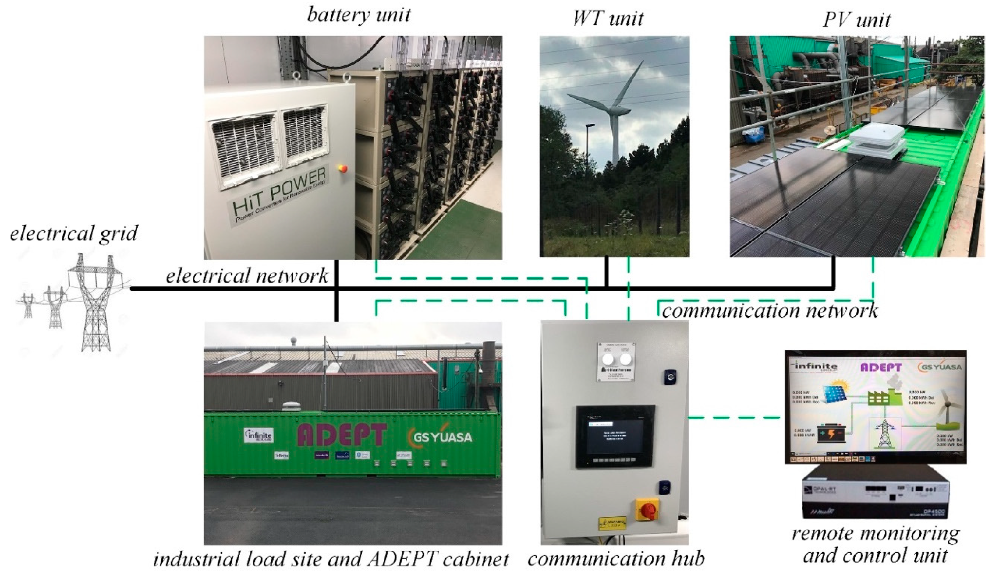
The ADEPT micro-grid consists of three DER units (wind turbine (WT), solar PV, and battery storage systems) and one industrial load that are integrated together and with the main electricity grid via the local power distribution system, as shown in
Figure 5. Part of the physical system architecture is depicted in
Figure 6, which shows the cabinet containing the battery energy storage unit, together with the three-phase inverter interface device. Similar inverter devices are used to integrate the additional DER units (wind and solar), all equipped with their local controllers that ensure the stable and reliable operation of the individual DERs in a decentralized manner (unit-level control).
In order to illustrate the ADEPT micro-grid architecture and operation as a CPS, we provide the necessary details that specify the different layers deployed for this particular example, which constitutes a small-scale application and does not involve some of the upper level decisions like those included in
Figure 1. Hence, starting from the lower level, each inverter synchronizes with the local grid using a phase-locked-loop (PLL) device to provide the angle
θg needed to transform the measured and control quantities from the
abc-reference frame to the synchronously rotating
dq-reference frame via Park transformation [
58]. Then, the currents injected from each DER unit and the local Point of Common Coupling (PCC) voltages are calculated in this frame as
Idi and
Iqi.
, respectively.
In the ADEPT system, a novel unit-level control structure is utilized where each inverter-interfaced DER unit is required to provide grid support through droop control implementation and additionally guarantees an inherent current limitation to protect each inverter from high currents under extreme scenarios (e.g., grid faults and unrealistic power demands from supervisory control). This novel current-limiting unit-level control design can be found in [
59], where the duty-ratio control inputs of each DER unit inverter were defined as:
where
is the grid angular frequency;
and
are the rated frequency and rated RMS voltage, respectively;
is the inverter filter inductance; and
is a virtual resistance introduced by the controller. For the rest of the controller gains and parameters, as well as the controller analysis, the reader is referred to [
59].
It is underlined that the unit-level control in Equations (7)–(12) matches the generic form of Equations (2) and (3), where
,
, and
, and it becomes clear that the real and reactive power injected by each DER unit represent functions of
, i.e.,
. Note that
represents the desired power signals obtained by the supervisory control, as is explained below. Hence, these DER units with their embedded unit-level control, together with the local electrical network that integrates them together, represent the physical part of the CPS architecture, as defined in
Figure 1.
In order to maximize the utilization of green and cheap electricity, as well as the economic benefits of the local consumer (load), e.g., avoid triad costs, an intelligent energy management system (EMS) has been formulated to optimize the operation of the micro-grid though the suitable control of the DER units. Since the DERs are integrated at nearby points of the electrical network, the EMS is designed to operate in a centralized manner, gathering the power generation, consumption, and storage data in a central data storage and management unit together with additional key information on the desired system performance, such as grid voltage, frequency, and battery state of charge. In particular, the central communication hub unit collects the injected power data from all DER units through suitable smart meter devices via a Modbus communication network. These data, together with the battery state-of-charge (SoC) information, are transferred to the supervisory control unit, which calculates the desired reference signals that are fed to the microcontroller of each DER unit via a dedicated industrial CAN communication protocol.
The supervisory control unit is formed using an OPAL RT device that implements the control algorithm that optimizes the economic operation of the ADEPT micro-grid system. Particularly for different optimization algorithms that include the continuously updated electricity price, grid voltage, and frequency, the total micro-grid power injected to the grid and state of charge requirements can be implemented through the OPAL RT system, subject to technical and economic constraints of the DER units. An example of such an optimal supervisory control design is given below, where the system dynamics are first discretized and then the minimization of the following function is obtained:
Here, the three DER units that are controllable include the battery, the PV system, and the WT system, they are included in the optimization problem. Based on the given electricity price that is obtained by connecting to the cloud and receiving the price value
, the cost function
is suitably formed to minimize the price of electricity consumed by the ADEPT micro-grid and also to minimize the reactive power injected to the main grid by the entire micro-grid. The optimization problem is solved under multiple constraints that include the discretized model of the units and the battery, where
and
are the DER units and battery models, respectively, calculated after discretization. In addition, the battery SoC and the desired power reference values
are required to be limited within a given range. Hence, it becomes clear that Equation (13) matches the constrained optimization problem in Equation (6). The outputs of this supervisory controller include the set point values
of the power injected by each DER unit in order to have a self-sustainable micro-grid with the maximum utilization of cheap and clean electricity from the renewable energy units.
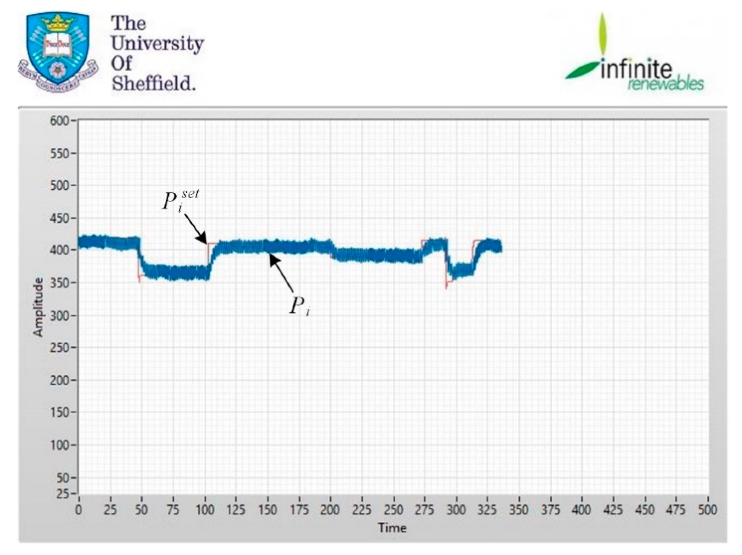
Figure 7 provides an example of the real power
injected by one DER unit within the ADEPT system and the reference value
obtained as the solution of the optimization problem that is solved at each discrete time step.
It should be mentioned that since in the ADEPT example all DER units are connected at nearby points of the network and a centralized control approach is needed, then the distributed control approach described in
Section 3.2 is not applicable in this example. However, such an approach can be useful in similar applications where the DER units are dispersed within the network or multiple ADEPT micro-grids are connected together.
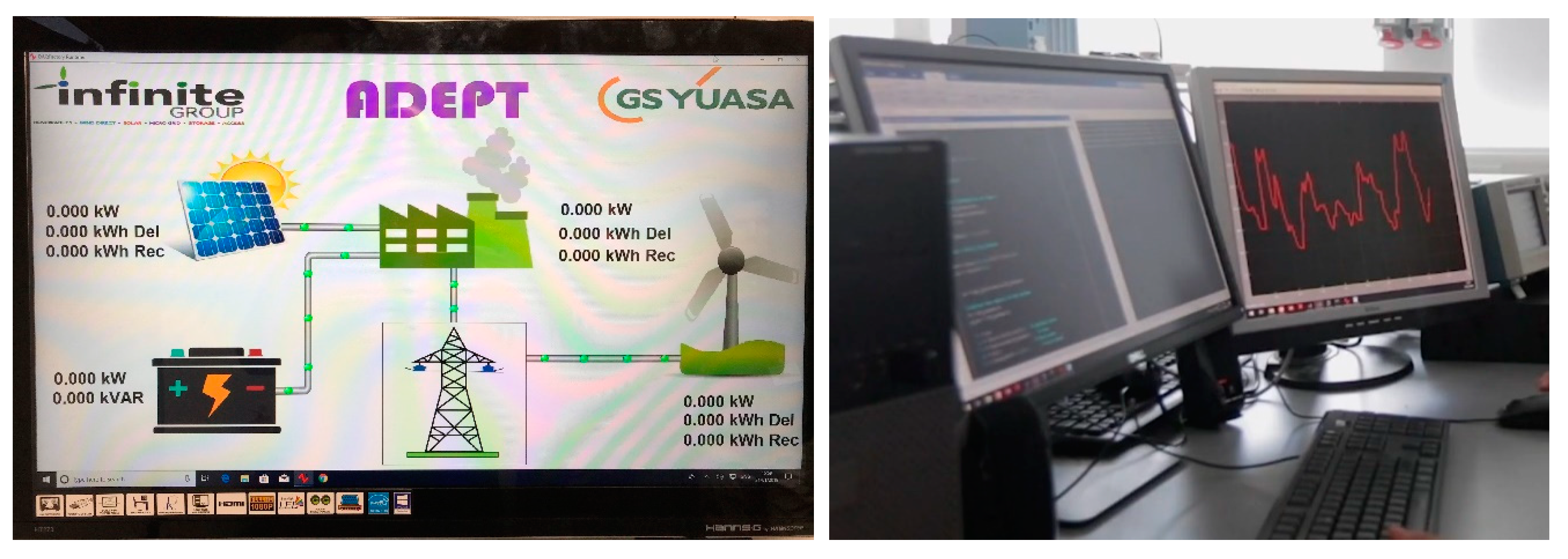
Finally, the optimal design and operation of the ADEPT micro-grid is visualized through an online platform (left side of
Figure 8) that indicates the power and energy data generated/consumed by each DER unit. Though the central data storage and management unit is located at the ADEPT micro-grid site, the OPAL RT device that implements the supervisory control is located at the University of Sheffield laboratory (right side of
Figure 8) and communicates with the central unit through a secure network. This provides the researchers at the University of Sheffield with the opportunity to easily modify and test different supervisory control and optimization techniques from a remote location due to the flexibility offered by the OPAL RT software.
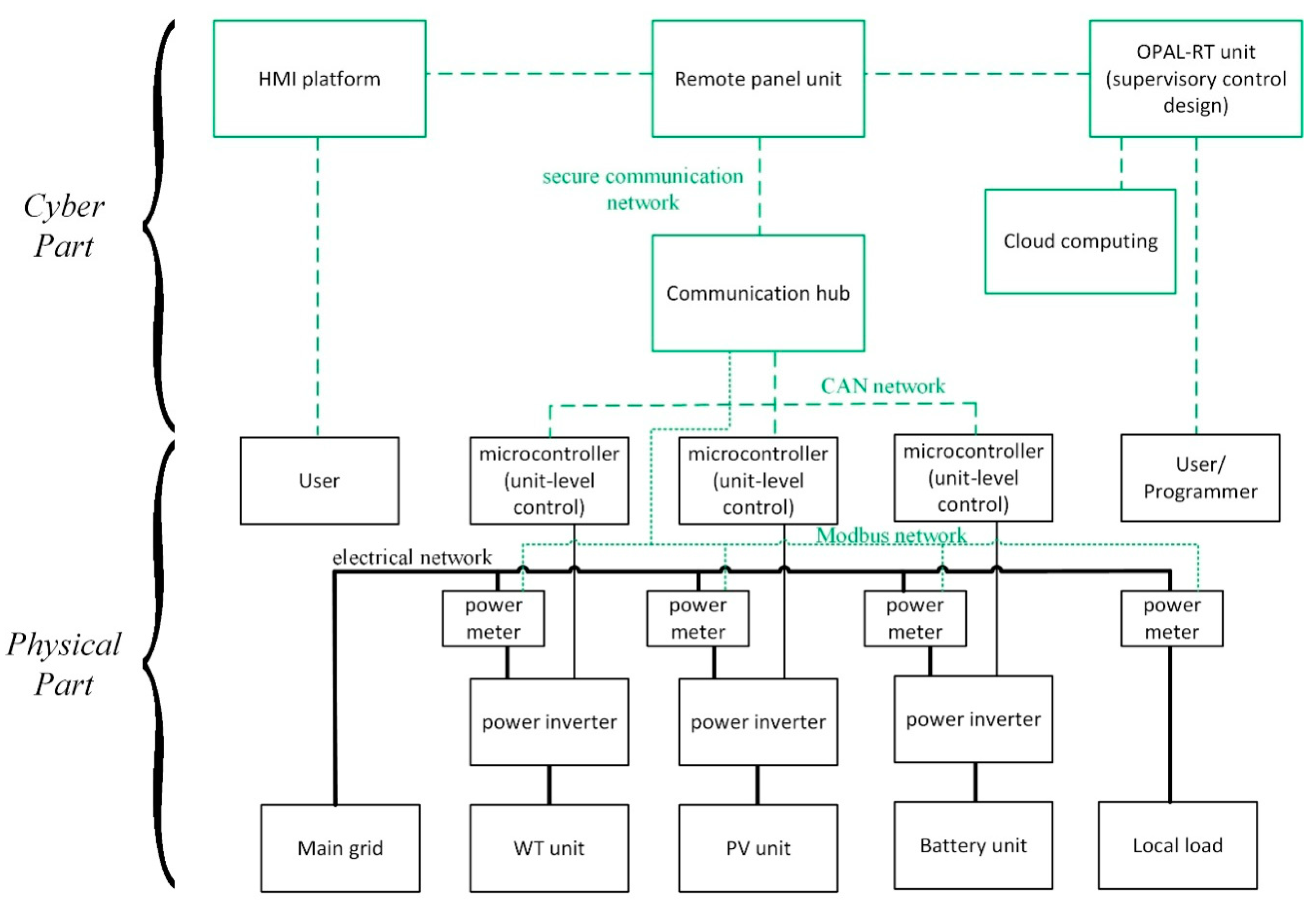
As a result, the communication network, the remote monitoring and control system, and the central computation device that incorporates the supervisory control and optimization design represent the cyber part of the proposed CPS architecture (as depicted in
Figure 1).
Figure 9 shows the entire CPS architecture of the ADEPT system.
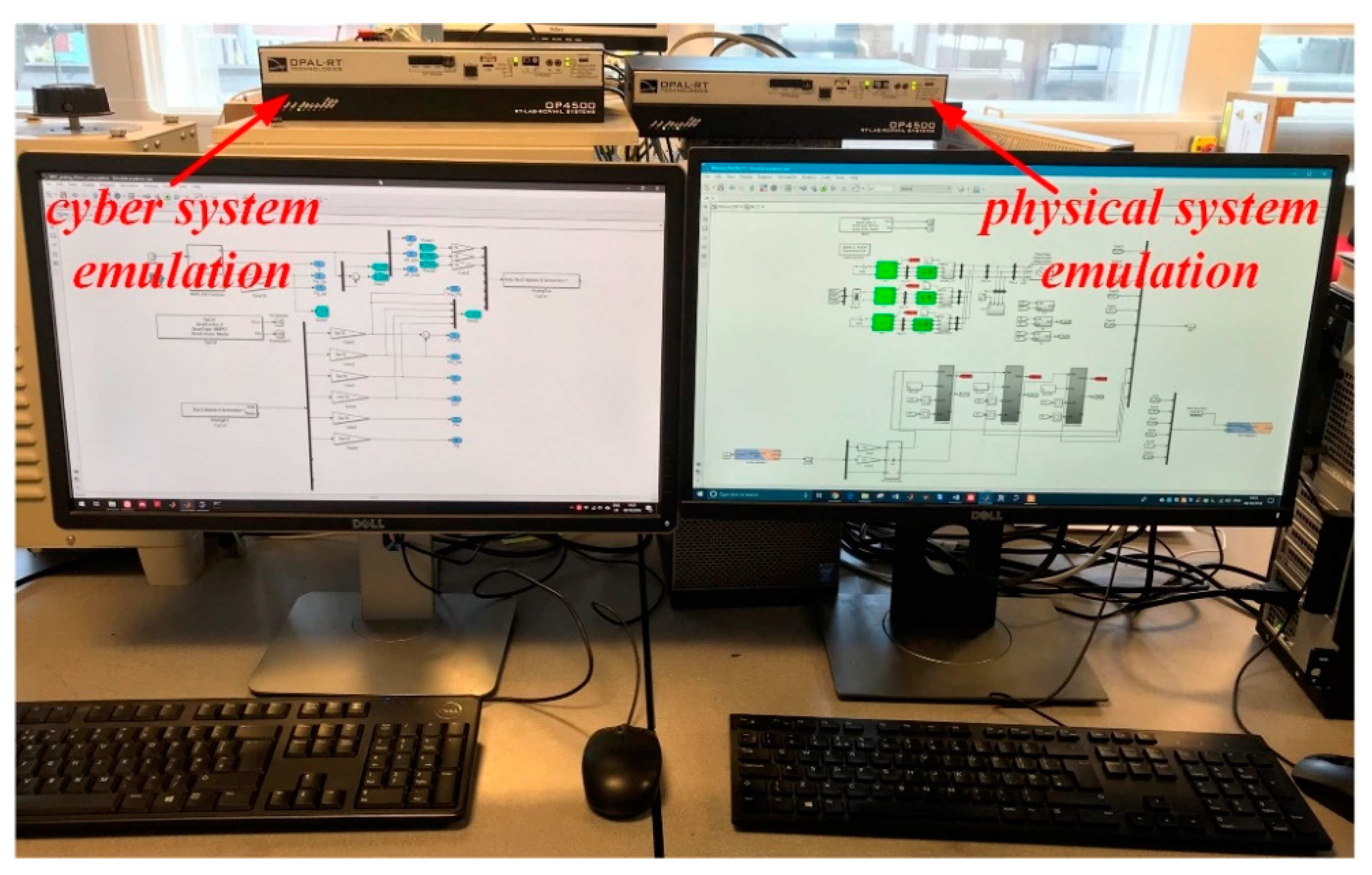
Though the details presented above clearly describe the actual CPS infrastructure of the ADEPT micro-grid system as it currently exists, as well as how it links to the proposed generic CPS framework, additional functions and capabilities can be obtained from this particular example for future research purposes. It is clear that when scaling up the presented application, e.g., to include a large number of micro-grids with higher renewable energy penetration and other DERs, more complex upper level computations are needed to manage the whole system under social/environmental and more complicated economic criteria. Furthermore, the technical implementation on the basis of the proposed CPS framework is still an open problem where many information and communication aspects can be used. Coming back into our implementation, it is additionally noted that since the OPAL RT unit offers unique real-time simulation capabilities, it can be also used as an ideal testbed for implementing a CPS co-simulation design in order to assist in this direction (
Figure 10). As it has been highlighted in the literature, co-simulation CPS testbeds are ideal for proof-of-concept prototyping, system validation, and analysis, and they often use a combination of hardware/software for modelling the power system (e.g., OPAL RT, RTDS, and Matlab) and the control and communication system (e.g., OPNET and OMNET++) [
5,
6,
17]. In the ADEPT project, since the supervisory control design is implemented via an OPAL-RT unit, a second OPAL-RT unit can be utilized to emulate the physical system of the micro-grid, as shown in
Figure 8. This testbed allows for the initial testing and design of the control and communication system, while after the completion of the actual micro-grid, it can be used to enable additional functionalities, such as the emulation of more DER units that can be added in the micro-grid or multiple ADEPT micro-grids integrated together for testing possible extensions or the scaling up of the existing system.


