Article

The Influence of VSC–HVDC Reactive Power Control Mode on AC Power System Stability

1
State Grid Hubei Electric Power Research Institute, Wuhan 430077, China
2
State Grid Hubei Electric Power Co., Ltd, Wuhan 430077, China
3
Central China Branch of State Grid Corporation of China, Wuhan 430077, China
*
Author to whom correspondence should be addressed.
Energies 2020, 13(7), 1677; https://doi.org/10.3390/en13071677
Submission received: 10 January 2020 / Revised: 20 March 2020 / Accepted: 26 March 2020 / Published: 3 April 2020
(This article belongs to the Special Issue Modern Power System Dynamics, Stability and Control)

Abstract

:
Voltage source converter-based high-voltage direct current (VSC-HVDC) has the advantage of fast and independent controllability on active and reactive power. This paper focuses on effects of commonly proposed reactive power control modes, constant reactive power control and AC voltage margin control. Based on the mathematical model of single machine infinity equivalent system with embedded VSC-HVDC, the influence of VSC-HVDC with different reactive power control strategies on transient stability and dynamic stability of the AC system is studied. Then case studies were conducted with a realistic model of grid. The dynamic responses of AC/DC systems for different VSC-HVDC reactive power control modes were compared in detail. It is shown that compared to constant reactive power control, AC voltage margin control can provide voltage support to enhance the transient angle stability of an AC system. However, the fluctuant reactive power injected into a weak AC system may adversely affect power system oscillation damping for VSC-HVDC with AC voltage margin control, if the parameters of the controller have not been optimized to suppress the low-frequency oscillation. The results of this paper can provide certain reference for the decision of an appropriate VSC-HVDC reactive power control mode in practice.

Graphical Abstract

1. Introduction

The voltage source converter high-voltage direct current (VSC-HVDC) project has the advantages of independent and rapid control over active and reactive power [1]. Due to this capability, VSC-HVDC has seen rapid development in aspects such as asynchronous grid interconnection, offshore wind farm integration and isolated island power supply [2].
Significant research efforts have been made regarding VSC-HVDC reactive power and voltage control and their impacts on the stability of AC systems [3,4]. Stability enhancement has been exploited in [5,6,7] by utilizing the VSC-HVDC controller or its auxiliary controllers. The influence of the VSC converter station on the short circuit ratio of an AC system is considered. The voltage support capability of the VSC-HVDC is quantitatively represented in [5], and a control strategy is developed to provide maximum reactive power support under AC grid faults. A new control strategy for the reactive-power injections of VSC is proposed in [6] to improve power system transient stability. Adaptive supplementary damping control of VSC-HVDC for interarea oscillation is presented in [7].
However, the study of [8,9,10] implies that the AC voltage regulation in the VSC-HVDC link may adversely affect the dynamic performance of the AC system. The reported case studies in [8] indicate that the embedded VSC-HVDC grid can aggravate interarea oscillations of the host AC system without supplementary control and based on the conventional dq-frame control structure. The main conclusion of [9] is that the DC voltage control of VSC contributes a variable damping torque, which can be positive or negative, at different levels of system load conditions. Meanwhile, it is found that AC voltage control affects the damping of power system oscillations little. The work in [10] shows that the AC voltage regulation in the VSC-HVDC link may adversely affect the dynamic performance of the host weak AC system under the multi-infeed VSC-HVDC scenario.
The literature above focuses on comparisons between situations with and without VSC-HVDC, or between different controller parameters. Little information regarding the impacts of VSC-HVDC with different reactive power control strategies on the stability of an AC system is presented. The impact of diverse reactive power control modes of a VSC-HVDC system on the transient stability is presented in [11]. However, this analysis did not consider different reactive power injections and absorption for the reactive power control modes since the change of reactive power operating condition in a VSC-HVDC system may alter the angular separation between generators, hence affecting the large-disturbance angle stability of the system. Four reactive power control strategies of VSC-HVDC are investigated in [12] to compare their impacts on small signal stability. The simulation results of two independent VSC-HVDC converters in a generic system show that AC voltage control in the converter with a lower short-circuit ratio aggravated the stability of the least damped mode compared to reactive power control. However, its conclusions are induced from numerical simulation results and lack general utility for other cases. Three commonly proposed reactive power controls of VSC-HVDC are compared in [13]. It focuses on advantages and limitations of different control schemes and the impact on voltage stability, but the impacts on other types of stability are not discussed.
Moreover, it is worth mentioning that the control of VSC will affect different types of stability of the whole system. The choice of the VSC control mode is dependent on the assessment of the impact of VSC-HVDC on all system dynamics. The improvement in the specific type of stability may be at the expense of other types of stability [14].
Besides, most of the prior art is not based on a realistic model of the grid. The presented control strategies and parameters optimized methods can be optimized in theory but may be not suitable in practice. The work of [5] is based on the Danish transmission grid model, and the work of [10,11,15] is based on the northern Scottish transmission model. These studies are restricted to the realistic grid with multi-infeed VSC-HVDC.
Comparison analysis of different control modes is important for the operation of a practical VSC-HVDC project. Reactive power control modes of the converter cannot be determined before we get a comprehensive knowledge about the influence of VSC-HVDC reactive power control modes on AC power system stability. To solve this problem, two reactive power control strategies commonly used in practice are considered, and two types of stability which are most concerned in safety and stability analysis are investigated in this paper. A comprehensive analysis of the impact of two VSC reactive power control modes on transient angle stability and dynamic stability are presented based on both theoretical analysis of mathematical mode and numerical simulation of a realistic model of gird. Their conclusions corroborate each other and provide a universal reference value for projects.
The rest of the paper is organized as follows. Section 2 presents a theoretical analysis of the impacts of VSC-HVDC with two reactive power control modes on the transient power angle stability and dynamic stability damping level of AC system based on the mathematical model of a simple system. Section 3 presents the results of a real system case study (Hubei power grid with embedded Chongqing-Hubei back-to-back VSC-HVDC). Section 4 presents the conclusions of the paper.

2. Analysis of the Influence of VSC Reactive Power Control Mode on the Stability of AC System

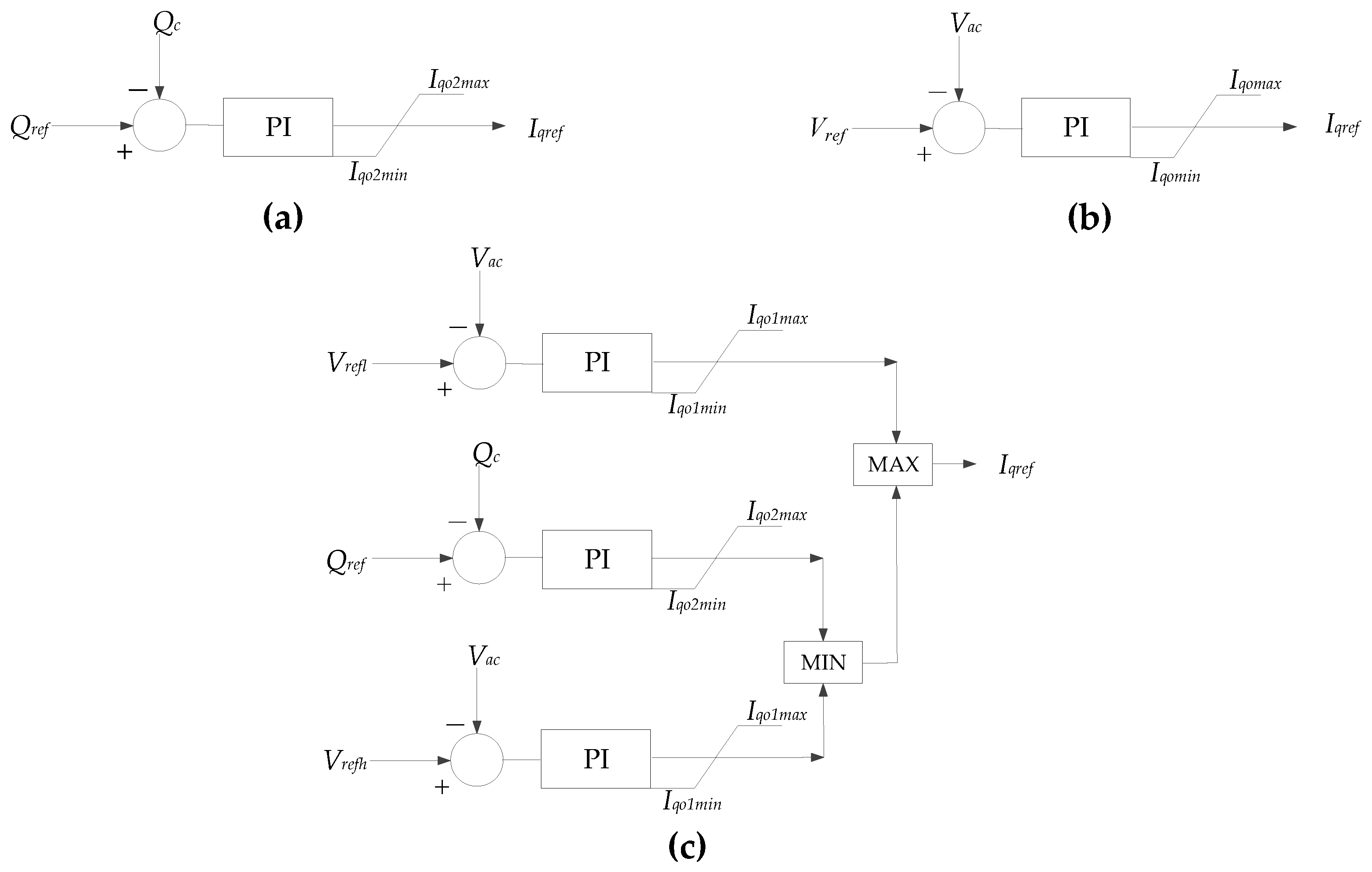
2.1. VSC-HVDC Reactive Power Control Mode

At present, direct current control, also known as vector control, is widely used in VSC-HVDC. Vector control generally adopts a double closed-loop control structure [16]. A decoupled control structure consisting of current feedback and voltage feed-forward is adopted in the inner current control loop which can track the reference current quickly. The outer loop is power regulators, which combines the inverse steady-state model with proportional-integral regulator and can control the active and reactive power separately.
This paper mainly discusses the control mode selection of the outer loop reactive power controller, which may be called AC voltage controller elsewhere. Three generic reactive power controllers for the VSC-HVDC system are shown in Figure 1: constant AC reactive power, constant AC voltage, and AC voltage margin control.
AC voltage margin control is essentially the constant voltage control mode with dead zone. Considering voltage fluctuations of the converter bus during AC power system operation in practice, AC voltage margin control is introduced to avoid frequency adjustments compared to constant voltage control mode. When the controlled bus voltage fluctuates within the allowable range (Vrefl, Vrefh), the objective of controller is to maintain the reactive power output of VSC-HVDC at the given value. When voltage fluctuation exceeds the upper (lower) limit, the objective of the controller is to maintain the voltage at the upper (lower) limit value. In such a case, VSC-HVDC may absorb (inject) a lot of reactive power from (to) the AC system. The dead zone (Vrefl, Vrefh) shall be determined according to the normal fluctuating range of the converter bus voltage throughout the year, with the need for voltage support under AC-side faults taken into account.

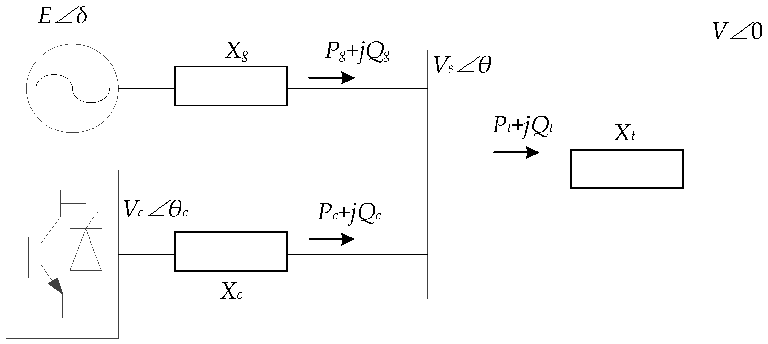
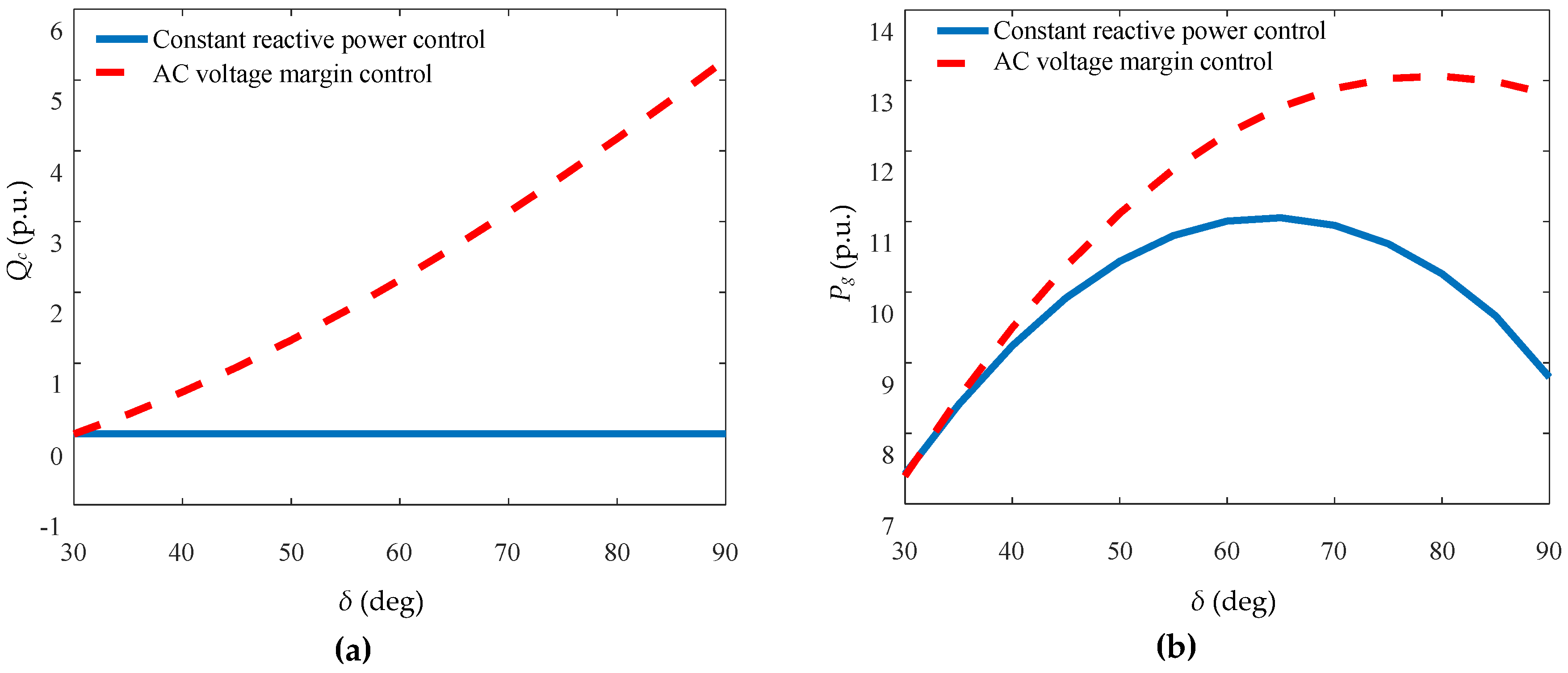
2.2. Influence of VSC Reactive Power Control Mode on Transient Angle Stability of Power System

The influence of the VSC-HVDC on the AC system is through the change of the converter bus voltage. It is essentially the influence of the change of the active and reactive power injected to the AC system. A simple system with an embedded VSC-HVDC and a synchronous generator is used to conduct theory analysis in this section, as shown in Figure 2. The receiving end is the infinite system bus, and its impedance is ignored.
The power of the generator injected into the system is
{ P g = E V s X g sin ( δ θ ) Q g = E V s X g cos ( δ θ ) - V s 2 X g
Ignoring the dynamic process of the control loop, for VSC-HVDC
{ P c = V c V s X c sin ( θ c θ ) Q c = V c V s X c cos ( θ c θ ) - V s 2 X c
For the AC network,
{ P g + P c V s V X t sin θ = 0 Q g + Q c V s 2 X t + V s V X t cos θ = 0
Equations (1)–(3) contain six equations. Bus voltage (V) of the infinite external system can be considered as constant 1.0. Since the parameters (Xg, Xc, Xt) are known, there are 10 variables (E, δ, Pg, Qg, Vc, θc, Pc, Qc, Vs, θ) to be solved. Given four of them, the rest can be known by solving the equations.
It is assumed that VSC-HVDC operates in the control mode of constant active power and constant reactive power. In this case, Pc = Pref and Qc = Qref. Given the value of E, we can get the output reactive power curve with the variation of the generator angle. Similarly, we can also get the curve of VSC-HVDC output reactive power when it operates in the control mode of constant active power and constant AC voltage. The characteristics of VSC-HVDC reactive power output under constant reactive power mode and constant AC voltage are compared in Figure 3.
It can be seen from Figure 3a that under the mode of constant AC voltage, with the increase of line transmission power, VSC-HVDC provides a large amount of reactive power to the connected AC system to maintain the AC voltage. The electromagnetic power characteristics of the generator under the two control modes are shown in Figure 3b. The limit of transmission capacity of the AC system under the constant reactive power control mode of VSC-HVDC is larger than that under the constant AC voltage mode. It means that in the transient course after fault the system will gain a larger deceleration area, that is, a higher ability to maintain transient stability.

2.3. Influence of VSC Reactive Power Control Mode on Dynamic Power Angle Stability of System
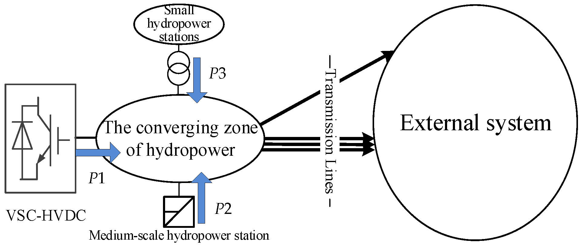
For the system shown in Figure 2 without the VSC-HVDC connection, angle, and frequency, the voltage of the generator will oscillate when applying small disturbance on it. The relationship among phases of power angle, frequency, and voltage can be examined by calculating their perturbation.
According to the superposition theorem in linear circuit, we have:
V ˙ s = X t X t + X g E δ + X g X t + X g V 0
Let E1 = Xt E/(Xt + Xg) and E2 = Xg V/(Xt + Xg). According to the law of cosines, the amplitude of Vs can be calculated by
| V s | = E 1 2 + E 2 2 + 2 E 1 E 2 cos δ
Assume δ = δ0 in steady-state operation, and the linear partial differential equation of Equation (5) is
Δ | V s | = - E 1 E 2 sin δ 0 E 1 2 + E 2 2 + 2 E 1 E 2 cos δ 0 Δ δ
From Equation (6), we can know that the phase of voltage amplitude is opposite that of the power angle during low frequency oscillation.
The angular frequency is the differential of the power angle, i.e.,
Δ ω = d Δ δ / d t
Equation (1) shows that the phase of it lags a power angle by 90°.
Combined with Equations (6) and (7), the phase difference between voltage amplitude variation and angular frequency is 90°. Therefore, the two control objectives of suppressing low frequency oscillations and maintaining the bus voltage cannot arrive at a complete agreement on the requirements for the dynamic reactive power compensation devices during the oscillation. Specifically, the requirements of suppressing low frequency oscillations and maintaining the bus voltage for dynamic reactive power compensation devices are opposite in two 1/4 periods in a period of oscillation.
Considering VSC-HVDC connected to the AC system, the phase of reactive current injected into the AC bus by VSC-HVDC lags behind bus voltage Vs by 90 degree. Iq > 0 indicates that VSC-HVDC injects inductive reactive power into the grid, and Iq < 0 indicates that VSC-HVDC injects capacitive reactive power into the grid.
I ˙ q = I q ( θ 90 )
According to the superposition theorem of linear circuit, the transmitted power to the bulk system can be expressed by the following equation:
P t = E V X t + X g sin δ + I q V X g X t + X g sin θ
The first item on the right side of the equation is the transmission power of the line without VSC-HVDC, and the second item is the change of transmission power caused by VSC-HVDC’s injected reactive current into the system. It can be seen that changing the direction of the VSC reactive current can change the amplitude of transmission power.
According to Equation (9), when the system frequency is lower than the rated frequency in the oscillation process, the transmission power on the line needs to be reduced. In this case, Iq < 0, i.e., VSC-HVDC injects capacitive reactive power to the AC system. Conversely, VSC absorbs capacitive reactive power when the system frequency is higher than the rated value.
For the objective of constant voltage, VSC-HVDC will inject capacitive reactive power into the system when the AC voltage of the access point is lower than its steady-state value. Instead, it will absorb capacitive reactive power in case of higher voltage.
As analyzed before, the phase difference between voltage amplitude variation and angular frequency is 90°. Under the constant AC voltage control mode, the control system calculates the deviation between the actual and reference voltage of the common point; then, the deviation reflects on the reactive current command by the PI regulator. It can be seen that the goal of constant AC voltage of VSC-HVDC may aggravate the power oscillation of the AC system, which is not conducive to the dynamic stability of the system.

3. Case Study

A hydropower collection and transmission system in Enshi of Hubei province is taken as an example to analyze the influence of the VSC-HVDC reactive power control mode on AC power system stability. The grid structure is shown in Figure 4. It contains three power sources:
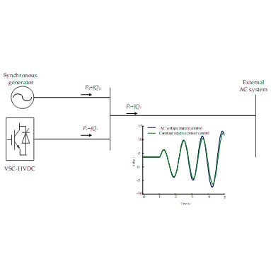
  • VSC-HVDC transmission system; its transmitted power is denoted as P1, and its rated power is 2000 MW.
  • Medium-scale hydropower station connected to high-voltage power grid; it contains 4 × 460 MW units, and its output is denoted as P2.
  • Small hydropower stations connected to low and medium voltage power grid; the power injected to the 500 kV grid is denoted as P3, and its maximum allowed value is 1000 MW.
Power from the three sources are collected and then transmitted to external system through four 500 kV transmission lines.
Considering two control modes, constant reactive power control. In this case, the AC bus at the primary side of the converter transformer is a controlled bus for the AC voltage margin control mode, the reference voltage is 525 kV, and the setting margin is ±5 kV. Specifically, the value of Qref for VSC-HVDC with a constant reactive power control mode is the same as that for AC voltage margin control mode. Thus, the effect of prefault steady-state power flow on analysis results for two reactive power control modes are eliminated.

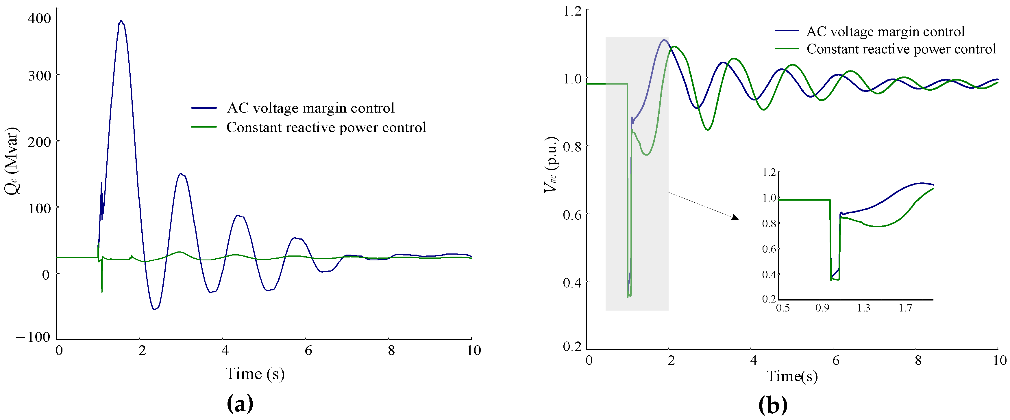
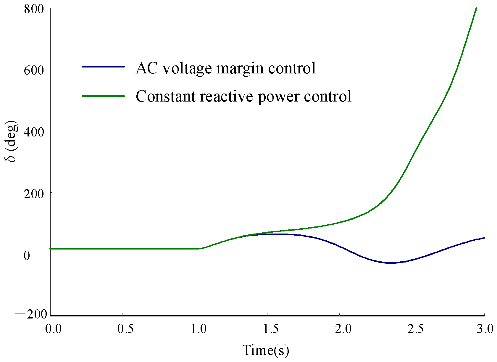
3.1. The Influence of VSC-HVDC Reactive Power Control Mode on AC Power System Stability

For the system in Figure 4, comparisons of dynamic response of AC/DC system for two control modes under AC grid fault condition are displayed in Figure 5. It is an example of cases in which the system can maintain stability under fault. The direction of VSC-HVDC injecting reactive power to the AC system is set as the positive direction, as seen below.
As shown in the Figure 5, under the AC voltage margin control mode, the outer-loop controller of VSC-HVDC responds quickly and increases the active current command when the voltage deviation of the controlled bus exceeds 5 kV. Correspondingly, the reactive power output of VSC-HVDC injected to an AC system will increase and support the fast recovery of AC voltage. In contrast, the reactive power output of VSC-HVDC with constant reactive power control does not change much under AC-side fault. Correspondingly, AC voltage recovered slowly after the fault clearing due to the lack of sufficient dynamic reactive power. It indicates that the voltage support capability of the VSC-HVDC with AC voltage margin control mode is greater than that with constant reactive power control mode.
Further, we found that transient stability of the whole system can be entirely different for two control modes when the system is near the stability boundary. For example, VSC-HVDC is running under constant active and AC voltage margin mode, and the transmitted power is 1000MW; active power of small hydropower stations injected to the 500 kV grid is 1000 MW; the medium-scale hydropower station is fully loaded; the system can keep transient stability after any N-1 contingency. Other things equal, the AC voltage margin mode is changed to constant reactive power control. Hydropower stations mentioned above will lose synchronism to the rest of the system under some N-1 contingencies. The power angle of a medium-scale hydropower generator vs. other generators is shown in Figure 6.
From the comparison of the simulation results above, we can know that AC voltage margin control mode is more conductive for the transient stability after serious faults compared to the constant reactive power control, which is consistent with the theory analysis in Section 2. To clearly display the impact of VSC-HVDC control modes on transient stability of AC system, the power transfer capacity of the system (i.e., allowable maximum transmission capacity of the four 500 kV lines in Figure 4) restricted by transient stability under various combinations of three power sources output is listed in Table 1.
It can be seen from Table 1 that considering the restriction of transient stability after N-1 contingency, power transfer capacity of transmission lines for AC voltage margin control mode of VSC-HVDC is greater than that for constant reactive power control mode by 400–1000 MW. Therefore, adopting an AC voltage margin control mode is more advantageous to the utility of transmission capacity considering transient stability.
In the circumstances of the medium-scale hydropower station being cut off, the difference between transmission capacity of the system for two reactive power control modes is more obvious. This is because both medium-scale hydropower generators and VSC will provide reactive power to support the transient stability of the system as dynamic reactive power sources, since the long distance between small hydropower generators and 500 kV transmission system limits the transmitting of reactive power support from small hydropower generators. When the medium-scale hydropower station is cut off, VSC-HVDC is the only dynamic reactive power source near the converter station. In such circumstances, its capability for dynamic reactive support is more important for the transient stability of the host AC system. Thus, power transfer capacity restricted by transient stability is more sensitive to the change of reactive power control modes with medium-scale hydropower station off.

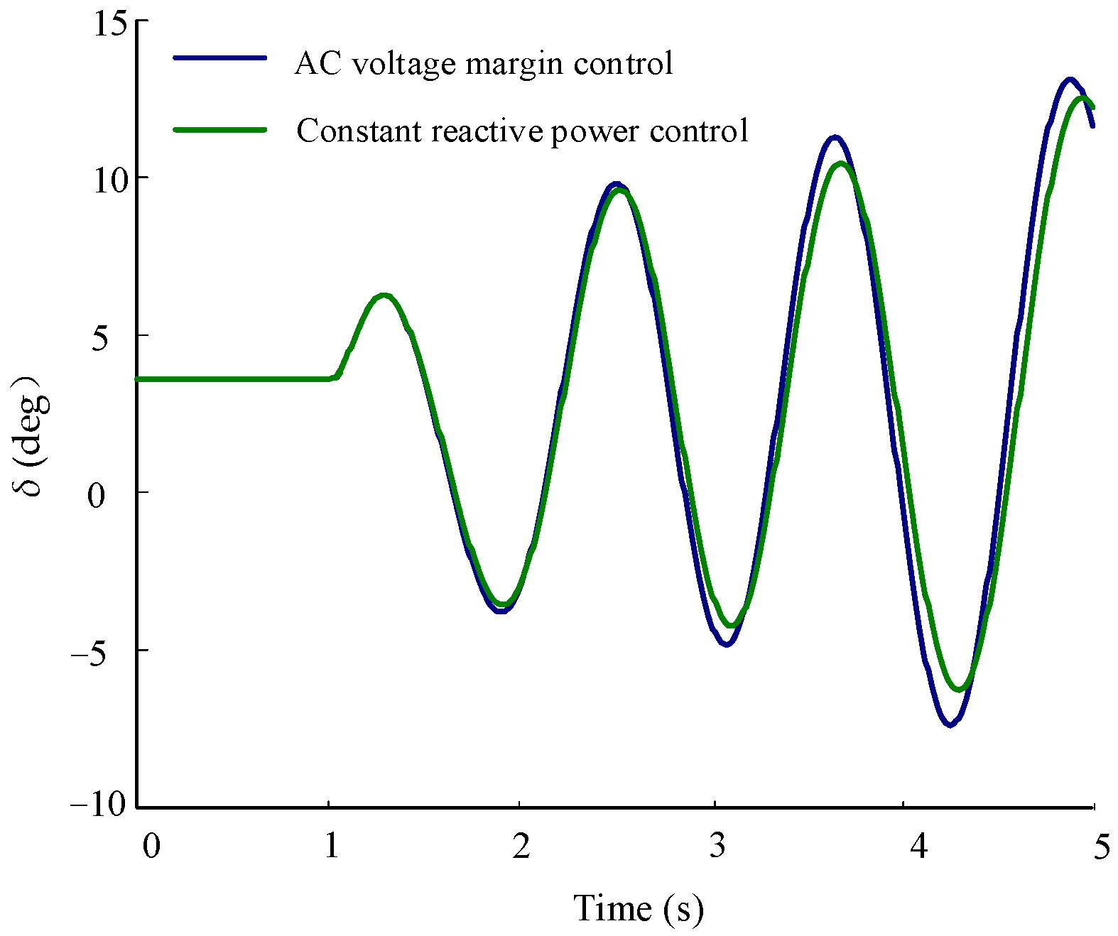
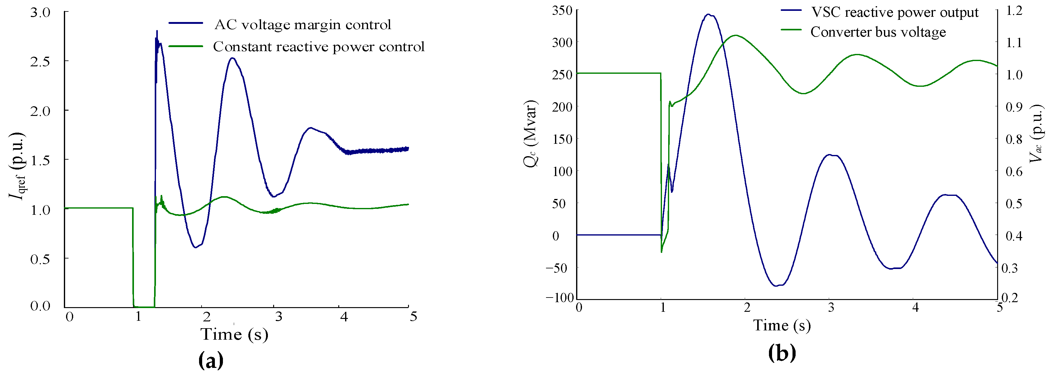
3.2. The Influence of VSC-HVDC Reactive Power Control Mode on Dynamic Stability

Through contingency screening by considering various power generation scenarios and locations for generators, we found that a few N-1 contingencies may excite interarea oscillation mode of hydropower generators against other generators in external system. The dynamic stability problem is more serious in cases of heavy flow. The most unfavorable flow condition in which VSC-HVDC and generators nearby are in full power operation is used to compare the different dynamic responses of AC/DC system under two control modes. Power angle of hydropower generator under two VSC control modes is showed in Figure 7.
It can be seen from Figure 7 that electromechanical oscillations and divergence occur after fault clearing. The amplitude of oscillations under VSC AC voltage margin control is a little larger than that under constant reactive power control.
Applying a fault to the system, simulation results of VSC q-axis current command under two control modes are shown in Figure 8a. Reactive power of VSC and voltage of VSC converter bus under two control modes are displayed in Figure 8b.
As seen in Figure 8, VSC-HVDC controllers under AC voltage margin mode quickly reacted to the voltage reduction of the controlled bus and reactive power output of VSC-HVDC fluctuated with voltage variations. The phase of reactive power current lags the voltage by 90 degrees. When the converter bus voltage is lower than its setting value, VSC will inject capacitive reactive power into the AC system; conversely, when the converter bus voltage is higher than its setting value, VSC will absorb reactive power from the AC system. From the analysis of Section 2.3, the fluctuations of VSC reactive power will encourage the oscillation of transmission power on AC lines near the VSC converter and may exert a bad effect on the dynamic stability of system.
We analyzed the active power data of the generator during system oscillation using the prony algorithm, and the results are listed in Table 2. There is one dominant interarea mode of 0.7 Hz. The damping ratio of the oscillation mode for AC voltage margin control is a little lower than that for constant reactive power control. Modal analysis is performed on the postfault system, and we found one interarea mode in which medium-scale and small hydropower generators oscillate against the other generators in the system. The frequency and damping ratio for that mode are 0.78 Hz and 1.9%, respectively. The results of modal analysis are consistent with those based on the prony method.
The permitted transfer capacity of VSC-HVDC in operation is limited by the dynamic stability of its host AC system. Compared to the AC voltage margin control mode, permitted transfer capacity of VSC-HVDC with constant reactive power control is greater. The dynamic behavior of VSC-HVDC is closely related to the parameters of its controllers. Therefore, the current parameters of the controller are unfavorable for dynamic stability of the whole system. For making good use of the AC/DC transmission system, optimal parameters of reactive power controller should be obtained considering the damping characteristics of the AC system, especially for weak systems and VSC-HVDC systems with AC voltage margin mode.

4. Conclusions

Based on the mathematical model analysis of a simple power system and the time-domain simulation of an actual power system, this paper makes a comparative study on the influence of VSC-HVDC with two reactive power control modes on the transient stability and dynamic stability of the AC system. The conclusions are as follows.
  • Compared with the constant reactive power control mode, VSC-HVDC with AC voltage margin control mode can provide voltage support during AC-side disturbances, which is beneficial to the recovery of bus voltage and transient stability of the whole system.
  • Under AC voltage margin control mode, the reactive power fluctuation injected into the AC system by VSC-HVDC may have an adverse effect on power system oscillation damping. Parameters optimization of the VSC-HVDC reactive power controller is necessary based on the analysis of system oscillatory modes, especially for weak system.

Author Contributions

Y.W. designed the study, analyze the data, and write the manuscript; Y.Z. and D.L. helped conceptualize the study; D.S. helped conduct the study; K.C. helped project administration; K.Z. and D.C. helped review and editing the manuscript. All authors have read and agreed to the published version of the manuscript.

Funding

This work was funded by the State Grid Science and Technology Project, grant number 521532190003.

Conflicts of Interest

The authors declare no conflicts of interest.

Nomenclature

Eδinternal potential of generator
Pgactive power output of generator
Vcθcvoltage at AC-side of VSC-HVDC
Pcactive power output of VSC-HVDC
Xtreactance of transmission line
ωangular frequency of power angle
Prefreference value of active power
Idrefreference for active current
Vacvoltage of AC bus
Iqreactive current
Xgequivalent reactance of generator
Qgreactive power output of generator
Xccommutated reactance of converter
Qcreactive power output of VSC-HVDC
Vsθvoltage at the point of common coupling
Vbus voltage of external infinite system
Qrefreference value of reactive power
Iqrefreference for reactive current
Vrefreference value of Vac
p.u.per unit

References

  1. Flourentzou, N.; Agelidis, V.G.; Demetriades, G.D. VSC-Based HVDC Power Transmission Systems: An Overview. IEEE Trans. Power Electron. 2009, 24, 592–602. [Google Scholar] [CrossRef]
  2. Bresesti, P.; Kling, W.L.; Hendriks, R.L.; Vailati, R. HVDC connection of offshore wind farms to the transmission system. IEEE Trans. Energy Convers. 2007, 22, 37–43. [Google Scholar] [CrossRef]
  3. Shah, R.; Sánchez, J.C.; Preece, R.; Barnes, M. Stability and control of mixed AC–DC systems with VSC-HVDC: A review. IET Gener. Trans. Distrib. 2018, 12, 2207–2219. [Google Scholar] [CrossRef]
  4. Li, G.J.; Lie, T.T.; Sun, Y.Z.; Ruan, S.Y.; Peng, L.; Li, X. Applications of VSC-Based HVDC in Power System Stability Enhancement. In Proceedings of the 2005 International Power Engineering Conference, Singapore, 29 November–2 December 2005; pp. 1–376. [Google Scholar] [CrossRef]
  5. Liu, Y.; Chen, Z. A Flexible Power Control Method of VSC-HVDC Link for the Enhancement of Effective Short-Circuit Ratio in a Hybrid Multi-Infeed HVDC System. IEEE Trans. Power Syst. 2013, 28, 1568–1581. [Google Scholar] [CrossRef]
  6. Renedo, J.; García-Cerrada, A.; Rouco, L. Reactive-Power Coordination in VSC-HVDC Multi-Terminal Systems for Transient Stability Improvement. IEEE Trans. Power Syst. 2017, 32, 3758–3767. [Google Scholar] [CrossRef]
  7. Shen, Y.; Yao, W.; Wen, J.Y.; He, H.; Chen, W. Adaptive Supplementary Damping Control of VSC-HVDC for Interarea Oscillation Using GrHDP. IEEE Trans. Power Syst. 2018, 33, 1777–1789. [Google Scholar] [CrossRef]
  8. Ajaei, F.B.; Iravani, R. Dynamic interactions of the MMC-HVDC grid and its host AC system due to AC-side disturbances. IEEE Trans. Power Deliv. 2016, 31, 1289–1298. [Google Scholar] [CrossRef]
  9. Du, W.J.; Wang, H.F.; Cheng, S.J.; Dunn, R. Effect of embedded voltage source converter on power system oscillation damping. Sci. China Technol. Sci. 2010, 53, 892–901. [Google Scholar] [CrossRef]
  10. Shah, R.; Preece, R.; Barnes, M. The Impact of Voltage Regulation of Multi-infeed VSC-HVDC on Power System Stability. IEEE Trans. Energy Convers. 2018, 33, 1614–1627. [Google Scholar] [CrossRef]
  11. Arunprasanth, S.; Annakkage, U.D.; Karawita, C.; Kuffel, R. Impact of VSC HVdc on AC System Generation. In Proceedings of the 13th IET International Conference on AC and DC Power Transmission, Manchester, UK, 14–16 February 2017; pp. 1–6. [Google Scholar] [CrossRef]
  12. Grdenić, G.; Delimar, M.; Beerten, J. Comparative Analysis on Small-Signal Stability of Multi-Infeed VSC HVDC System with Different Reactive Power Control Strategies. IEEE Access 2019, 7, 151724–151732. [Google Scholar] [CrossRef]
  13. Bernat, J.O.; Preece, R. Impact of VSC-HVDC Reactive Power Control Schemes on Voltage Stability. In Proceedings of the 2019 IEEE PowerTech, Milan, Italy, 23–27 June 2019; pp. 1–6. [Google Scholar] [CrossRef]
  14. Mochamad, R.F.; Preece, R. Assessing the Impact of VSC-HVDC on the Interdependence of Power System Dynamic Performance in Uncertain Mixed AC/DC Systems. IEEE Trans. Power Syst. 2020, 35, 63–74. [Google Scholar] [CrossRef]
  15. Shah, R.; Preece, R.; Barnes, M. Role of Multi-Infeed VSC-HVDC on Dynamic Behavior of Future North Scotland Transmission System. In Proceedings of the 13th IET International Conference on AC and DC Power Transmission, Manchester, UK, 14–16 February 2017; pp. 1–6. [Google Scholar] [CrossRef]
  16. Kazmierkowski, M.P.; Malesani, L. Current control techniques for three-phase voltage-source PWM converters: A survey. IEEE Trans. Power Electron. 1998, 45, 691–703. [Google Scholar] [CrossRef]
Figure 1. Three reactive power controllers for voltage source converter high-voltage direct current (VSC-HVDC) link. (a) Constant reactive power control; (b) constant AC voltage control; (c) AC voltage margin control.
Energies 13 01677 g001
Figure 2. Single machine infinity equivalent system with VSC-HVDC.
Energies 13 01677 g002
Figure 3. Comparisons of different VSC-HVDC control strategies of q-axis current. (a) VSC-HVDC reactive power; (b) generator’s power characteristics.
Energies 13 01677 g003
Figure 4. Schematic diagram of a practical transmission system with VSC-HVDC.
Energies 13 01677 g004
Figure 5. Transient responses of AC/DC system under different reactive power control modes. (a) Reactive power output of VSC-HVDC; (b) bus voltage at AC-side of the converter.
Energies 13 01677 g005
Figure 6. Generator angles after AC system fault under different VSC-HVDC control modes.
Energies 13 01677 g006
Figure 7. Generator angle oscillations under different VSC-HVDC control modes.
Energies 13 01677 g007
Figure 8. Dynamic responses for different reactive power control modes under AC-side fault. (a) q axis current command of converter; (b) voltage of controlled bus and reactive power output of VSC-HVDC.
Energies 13 01677 g008
Table 1. Power transfer capacity of the system restricted by transient stability under various combinations of three power sources output.
Reactive Power Control ModeP3 (MW)P2 (MW)P1 (MW)Power Transfer Capacity of the System (MW)
AC voltage margin control1000184010003820
1000020002960
350184020004030
Constant reactive power control100018406003420
1000010001980
200184020003950
Table 2. The impact of reactive power control modes on damping characteristic of power system.
Control ModesFrequency (Hz)Damping Ratio (%)
AC voltage margin control0.73−0.8
Constant reactive power control0.72−0.6

